

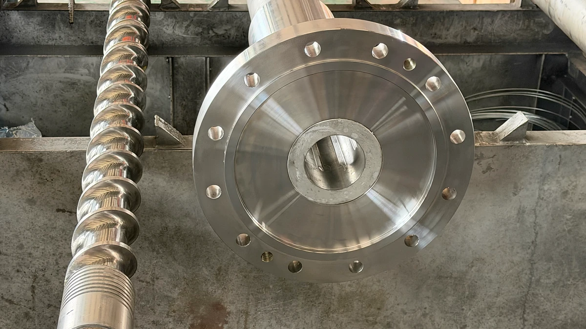
What Makes Single Screw Extruder Barrel Wear Different
Single screw extruder barrel wear is the progressive enlargement of the barrel's internal bore diameter caused by mechanical, chemical, and thermal interactions between the barrel inner surface, the rotating screw flights, and the polymer melt. Over time, these forces erode the barrel wall, widening the gap between the screw and barrel and steadily degrading extrusion performance. While that definition applies broadly, the way this wear develops — and the damage it inflicts — is fundamentally different in single screw systems compared to twin screw machines.
Most resources on extruder wear lump all configurations together. That approach misses the point. A single screw extruder behaves nothing like a twin screw when it comes to wear patterns, consequences, and the urgency of corrective action. Understanding the distinction is the first step toward protecting your equipment and your bottom line.
What Is Barrel Wear in Single Screw Extrusion
Imagine a single rotating screw pushing polymer forward through a tight cylindrical bore. The gap between the outermost edge of the screw flight and the barrel's inside diameter — known as the flight clearance — is deliberately kept extremely small. Industry-standard screw to barrel clearance tolerance typically follows a rule of thumb: roughly 0.001 inch per side for every inch of nominal screw diameter. A 3.5-inch extruder, for instance, ships with a flight clearance of about 0.004 inch per side and a barrel ID tolerance of just 0.001 inch oversize.
That razor-thin gap is not arbitrary. It controls heat transfer, shear rate, and — most critically — the machine's ability to move material forward. As barrel bore enlargement occurs through single screw extrusion service life, this clearance widens, and a cascade of performance problems follows: reduced output, rising melt temperatures, and deteriorating product quality.
Why Single Screw Systems Are Uniquely Vulnerable
Single screw extruders rely on a conveying principle called drag flow. The polymer is pulled forward primarily by friction and viscous drag between the melt and the barrel wall. There are no intermeshing elements pushing material along — just one screw rotating inside one barrel. This asymmetric design creates unidirectional contact, meaning the screw consistently presses against specific regions of the barrel wall due to asymmetric pressure distribution in the screw channels. The result is concentrated, localized wear rather than the more evenly distributed patterns you'll find in a co-rotating twin screw system.
The drag flow conveying barrel wear effect is what makes this configuration so sensitive to clearance changes. Even a small increase in the gap between the flight tip and barrel wall allows molten polymer to leak backward over the flights — a phenomenon called leakage flow or pressure-driven backflow. In a twin screw extruder, positive-displacement conveying helps compensate for clearance increases. A single screw machine has no such safety net.
Increasing screw-to-barrel clearance directly undermines the drag-flow conveying mechanism that single screw extruders rely on, making barrel wear disproportionately damaging compared to twin screw systems. A clearance increase that might cause a 5% efficiency loss in a twin screw can trigger a 13% or greater rate reduction in a single screw extruder.
The primary single screw extruder barrel wear causes — abrasive fillers scoring the surface, corrosive polymers chemically attacking the liner, and metal-to-metal galling from misalignment or solids wedging — all feed into this same vulnerability. Each mechanism widens the clearance, and every fraction of a thousandth of an inch lost translates directly into reduced conveying efficiency, higher energy consumption, and compromised product quality. The critical question is not whether your barrel is wearing, but where, how fast, and through which mechanism.
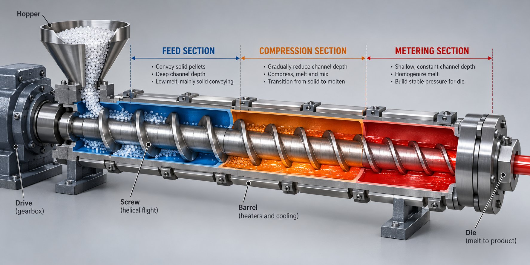
Zone-by-Zone Barrel Wear Analysis for Single Screw Extruders
A single screw extruder barrel is not one uniform surface doing one uniform job. It is three distinct functional zones stacked end to end — feed, compression, and metering — each facing different pressures, temperatures, and material states. Wear does not spread evenly across all three. It concentrates wherever the physics are most aggressive, and each zone leaves a different fingerprint of damage. An extruder barrel wear by zone analysis reveals exactly where your barrel is failing and, more importantly, why.
Feed Zone Wear Patterns and Root Causes
The feed zone is where cold, hard pellets enter the barrel from the hopper and begin moving forward. At this stage, the polymer is completely solid — think of it as a bed of rigid granules being compressed and dragged along the barrel wall by the screw flights. The primary feed zone barrel wear causes are straightforward: unmelted pellets act like sandpaper under high compressive forces, grinding against the barrel's inner surface with every screw revolution.
What makes this zone's wear pattern distinctive is its asymmetry. Gravity pulls the solid bed downward, and the solids bed pressure concentrates contact forces on the barrel wall opposite the hopper opening. You'll often find a crescent-shaped wear band — sometimes called bell-mouthing — right at the feed throat where hard, cold pellets slam into the bore at high velocity. Inadequate feed throat cooling accelerates this pattern because softened pellets create a sticky, high-friction layer that intensifies abrasion at the entry point. Recycled materials with irregular particle shapes or metal contaminants make things even worse.
The operational symptoms are subtle at first: inconsistent feeding, throughput fluctuations during startups, and the machine taking longer to stabilize after speed changes. You might even hear the difference — a shift in sound from the feed throat as pellets slip against rounded, worn flights instead of being gripped and driven forward.
Compression Zone as the Critical Wear Area
If one zone earns the title of wear hotspot, it is the compression section — also called the transition zone. Here, the screw channel depth decreases progressively, squeezing the material from a loose bed of pellets into a dense, partially melted mass. The physics are punishing: peak mechanical pressures, partially melted abrasive solids grinding against metal, and asymmetric forces that push the screw off-center.
Compression zone barrel wear in a single screw extruder is typically the most severe for a simple reason — this is where you have the worst combination of factors simultaneously. Hard, unmelted particles still exist in the polymer mix, but they are now being forced against the barrel wall under rapidly increasing pressure as the channel depth shrinks. The result is aggressive abrasive contact at precisely the point where mechanical stress peaks.
Analysis of thousands of rebuilt screws confirms that the transition section consistently shows the most severe wear. Glass-filled nylons, mineral-filled polypropylenes, and calcium carbonate compounds hit this zone especially hard because the partially melted solid bed still contains abrasive particles that have not yet been fully wetted by the melt. The symptoms are directly tied to melt quality: unmelted particles passing through to the die, surging output from inconsistent pressure development, and elevated melt temperatures from back-leakage over worn flight tips generating excess shear heat.
Metering Zone Wear and Corrosive Degradation
By the time polymer reaches the metering zone, it should be fully molten. That means the sandpaper effect of hard pellets is largely gone, and you might expect this section to be a low-wear area. For unfilled commodity resins, that is often true. But for chemically aggressive polymers, the metering zone becomes the site of a different — and equally destructive — attack.
Metering zone corrosive barrel wear occurs when resins like PVC, CPVC, and fluoropolymers release acidic byproducts at peak processing temperatures. PVC generates hydrochloric acid; fluoropolymers release hydrofluoric acid. These acids chemically etch the barrel bore, creating pitting and surface roughness that traps polymer and promotes further degradation. Corrosion weakens the entire surface layer, making it far more susceptible to subsequent mechanical removal — a synergistic one-two punch that accelerates total material loss beyond what either mechanism would cause alone.
Adhesive wear can also appear in this zone when polymer starvation or insufficient melt lubrication allows direct screw-to-barrel contact. The operational symptoms differ from other zones: you will notice declining pumping efficiency, head pressure instability, difficulty pushing material through fine-mesh screen packs, and — in corrosive resin applications — dark specks or metallic contamination in the finished product from corroded barrel material entering the melt stream.
The table below summarizes the wear characteristics across all three zones, giving you a quick reference to match what you are seeing in your barrel to its most likely cause.
| Zone | Primary Wear Mechanism | Typical Wear Pattern | Severity Level | Key Contributing Factors |
|---|---|---|---|---|
| Feed | Abrasive (solid pellet contact) | Asymmetric bell-mouthing at feed throat; crescent-shaped wear band opposite hopper opening | Moderate | Pellet hardness and shape, gravitational solids bed loading, inadequate feed throat cooling, recycled material contaminants |
| Compression / Transition | Abrasive and adhesive (partially melted solids under peak pressure) | Most severe bore enlargement; wear distributed along decreasing channel depth; possible screw deflection marks | High — often the most damaged zone | Decreasing channel depth increasing wall pressure, hard fillers not yet wetted by melt, asymmetric screw loading, high compression ratios |
| Metering | Corrosive and adhesive (chemical attack from melt degradation products) | Uniform pitting and surface etching from acid byproducts; localized galling from polymer starvation | Low to moderate for unfilled resins; high for chemically aggressive polymers | Resin chemistry (PVC, fluoropolymers), peak melt temperatures accelerating acid release, insufficient melt lubrication, extended residence time |
Each zone tells a distinct chapter of the wear story. Feed zone damage points to conveying problems. Compression zone damage reveals melting-stage failures. Metering zone damage signals pumping inefficiency or chemical attack. Recognizing which chapter your barrel is reading from is essential — but the full diagnosis also requires understanding the three core wear mechanisms themselves, because in real-world production, they rarely act in isolation.
Three Wear Mechanisms That Destroy Extruder Barrels
Barrel damage in a single screw extruder is not random. It follows predictable patterns driven by three distinct extruder barrel wear mechanism types: abrasive, corrosive, and adhesive. Each one attacks the barrel surface through a fundamentally different process, leaves a different forensic signature, and demands a different defensive strategy. Understanding which mechanism — or combination of mechanisms — is at work in your machine is the foundation of every smart repair, material selection, and maintenance decision that follows.
Here is the catch: these mechanisms almost never operate alone. In real-world production, they overlap and amplify each other in ways that can accelerate wear far beyond what any single mechanism would cause independently. Corrosion softens the surface, abrasion strips it away, and adhesive contact gouges what remains. Getting the diagnosis right means recognizing all three and understanding how they interact.
Abrasive Wear from Filled and Reinforced Compounds
Abrasive wear is the most common form of barrel degradation in plastics processing. It is a straightforward mechanical process — hard particles embedded in the polymer stream act like sandpaper, scoring and eroding the barrel's inner surface with every revolution of the screw. The harder the particle and the higher the contact pressure, the faster material is removed from the bore wall.
The culprits are familiar to anyone running filled or reinforced compounds. Glass fibers are among the most aggressive, with a Mohs hardness of approximately 6.5 — harder than most barrel liner materials. Mineral fillers like calcium carbonate, talc, and silica cause moderate to severe abrasion depending on particle size and loading levels. Pigment agglomerates, wood flour in composite formulations, and even metal flakes in specialty compounds all contribute to the abrasive attack. Abrasive wear in an extruder barrel processing glass-filled materials can reduce useful component life by 50% or more compared to running unfilled resins.
The damage pattern from abrasion is distinctive. You will see smooth, polished grooves running in the direction of screw rotation, a progressively enlarged bore diameter that increases uniformly around the circumference, and a gradual loss of the original surface finish. The wear tends to concentrate in areas where unmelted or partially melted material still contains solid abrasive particles — particularly the compression zone, as discussed in the previous section — but it can extend across the full barrel length in heavily filled applications.
How do you know abrasive wear is your primary problem? Look for these indicators:
- Smooth, uniform bore enlargement without pitting or cratering
- Directional scoring or polishing marks aligned with screw rotation
- Wear concentrated in zones where solid particles contact the barrel wall under pressure
- Screw flight tips worn flat and reduced in outside diameter
- Fine metallic particles visible in purge material or screen packs
- Gradual, predictable decline in output over weeks or months rather than sudden performance drops
Processing conditions play a direct role in the severity of abrasive wear. Running glass-filled nylons or mineral-filled polypropylenes at excessive screw speeds dramatically increases the rate of material removal because contact forces and the number of abrasive passes per minute both rise. Filler loading percentages matter too — jumping from 20% to 40% glass fiber content does not simply double the wear rate; it can increase it exponentially because the likelihood of particle-to-barrel contact rises nonlinearly with concentration.
Corrosive Wear from Chemically Aggressive Resins
Corrosive barrel wear attacks the barrel through chemistry rather than mechanics. Certain polymers release acidic byproducts when heated to processing temperatures, and those acids chemically dissolve the barrel's metallic surface layer from the inside out. The process is insidious because it can occur even in the absence of abrasive fillers, quietly undermining barrel integrity until the damage reaches critical levels.
PVC and CPVC are the most widely recognized offenders. During extrusion, PVC releases hydrochloric acid, which aggressively attacks barrel alloys with a high iron matrix. Acetal resins produce formic acid with similar corrosive effects. Fluoropolymers like PTFE and PVDF are even more destructive — they emit hydrofluoric acid, one of the most corrosive substances encountered in plastics processing, capable of rapidly degrading standard steel, nitrided liners, and even some bimetallic barrel materials.
What makes corrosive barrel wear from PVC and fluoropolymer processing so dangerous is the nature of the damage. Unlike abrasion, which gradually polishes and enlarges the bore, corrosion attacks the grain boundaries of the metal itself. It creates a rough, pitted surface full of micro-craters that trap polymer melt, promote stagnation, and generate degraded material that contaminates the product stream. The visual and physical signatures are unmistakable:
- Rough, pitted bore surface with irregular cratering rather than smooth enlargement
- Orange or reddish-brown discoloration on exposed barrel surfaces indicating iron oxidation
- Surface roughness that catches a fingernail when run across the bore
- Dark specks, black spots, or metallic contamination appearing in extruded product
- Accelerating wear rate — the damage gets worse faster over time as the protective surface layer is consumed
- Wear that is most pronounced in the metering zone where melt temperatures peak and acid concentration is highest
Temperature control is a critical variable. Every degree above the optimal processing window accelerates the rate of acid generation. Overheating PVC by just 10-15 degrees Celsius can multiply the release of hydrochloric acid significantly, turning a manageable corrosive environment into a barrel-destroying one. Extended residence times — caused by oversized barrels, low throughput rates, or frequent production stoppages — compound the problem by giving acids more time to react with the metal surface.
Adhesive Wear and Metal-to-Metal Galling
Adhesive wear is the least discussed of the three mechanisms, but it can cause catastrophic damage in a remarkably short time. It occurs when the polymer film separating the screw flight tip from the barrel wall is lost, allowing direct metal-to-metal contact. When two metal surfaces touch under high pressure and relative motion, microscopic welds form at contact points, then immediately fracture as the surfaces slide past each other. This cycle of welding and fracturing — known as galling — tears material from one surface and transfers it to the other, creating severe localized damage.
Several conditions invite adhesive wear in an extruder barrel. Polymer starvation — when the screw channel runs partially empty — eliminates the melt film that normally acts as a lubricant between flight tip and barrel wall. Misalignment between barrel and gearbox forces the screw to ride against one side of the bore. Poor screw design, where the melting capacity falls short of the feed rate, causes a phenomenon called solids wedging: unmelted material plugs the channel and generates lateral forces that push the screw hard against the barrel wall on the opposite side.
Incompatible metallurgy between the screw flight hardfacing and barrel liner material also increases galling risk. Softer alloys tend to gall more readily when contacting harder surfaces, making the choice of compatible screw and barrel materials essential for preventing adhesive damage.
The visual evidence of adhesive wear is dramatically different from abrasion or corrosion:
- Deep, irregular scoring or gouging concentrated in localized areas rather than distributed evenly
- Burrs or "rolled-over" edges on screw flight tips where metal has been torn and displaced
- Material transfer — smeared or welded metal deposits visible on either the barrel bore or screw flight surfaces
- Sudden, rapid performance deterioration rather than the gradual decline typical of abrasion
- Audible changes — metallic scraping or grinding sounds during screw rotation
- Damage patterns that are unilateral, appearing on one side of the barrel bore, indicating misalignment or deflection
In practice, these three mechanisms rarely exist in isolation. A barrel running corrosive PVC compounds with calcium carbonate filler faces simultaneous corrosive and abrasive attack. The acid weakens and roughens the surface layer, and the mineral particles immediately strip that compromised material away — a synergistic cycle that removes metal far faster than either mechanism alone. Similarly, a barrel suffering from misalignment-driven adhesive wear develops rough, scored patches that increase local friction, generating heat that accelerates any corrosive degradation already underway. Recognizing which combination is active in your specific operation is the key to choosing the right barrel metallurgy, setting appropriate processing parameters, and targeting inspections where damage is most likely to occur.
Knowing the mechanism is half the battle. The other half is understanding which polymers trigger which type of attack — and how your processing choices either accelerate or slow the destruction.
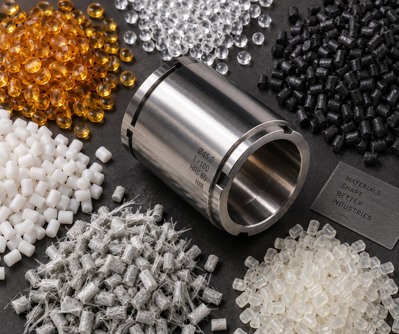
How Different Polymers Create Distinct Barrel Wear Profiles
Every resin family leaves its own mark on a barrel. A plant running unfilled HDPE and a plant running 40% glass-filled nylon might use identical extruder hardware, but after a year of operation their barrels will tell very different stories. Matching each polymer type to its dominant wear mechanism — and knowing the relative severity — lets you specify the right barrel protection from day one instead of reacting after the damage is done.
Polymer-to-Wear-Type Mapping Table
The following polymer type barrel wear severity chart categorizes common resin families by their primary attack on barrel surfaces. Use it as a quick reference when planning material changes, quoting new jobs, or specifying replacement barrels.
| Polymer Category | Example Resins | Primary Wear Mechanism | Relative Wear Severity | Recommended Barrel Protection |
|---|---|---|---|---|
| Glass-filled engineering plastics | PA6-GF30, PA66-GF33, PBT-GF30, PPA-GF45 | Abrasive | Severe | Bimetallic liner with high tungsten carbide content (e.g., iron-boron-tungsten carbide alloy) |
| Mineral-filled polyolefins | PP with calcium carbonate, PP with talc, PE with mica | Abrasive | Moderate | Bimetallic liner with iron-boron alloy or nitrided barrel with hardened flight tips |
| PVC and CPVC compounds | Rigid PVC, flexible PVC, CPVC pipe compounds | Corrosive | Moderate to severe | Nickel-rich bimetallic liner (nickel-boron alloy); low-iron-matrix barrel materials for PVC barrel corrosion prevention |
| Fluoropolymers | PTFE, PVDF, FEP, PFA, ETFE | Corrosive (severe) | Severe | High-nickel alloy or Hastelloy-lined barrel; nickel-boron bimetallic liner minimum |
| Wood-plastic composites (WPC) | PE-wood flour, PP-wood fiber blends | Combined abrasive and corrosive | Moderate to severe | Bimetallic liner with both abrasion and corrosion resistance; nickel-boron-tungsten carbide composite |
| Unfilled commodity polyolefins | HDPE, LDPE, LLDPE, PP homopolymer | Adhesive (mild) | Low | Standard nitrided barrel; adequate for most applications |
| Flame-retardant compounds | ABS-FR, PC/ABS-FR, PA6-FR with glass | Combined abrasive and corrosive | Moderate to severe | Bimetallic liner with corrosion-resistant matrix and high hardness for abrasion resistance |
A few things stand out from this chart. Glass-filled nylon barrel wear rate ranks among the highest of any polymer category — those glass fibers, with a Mohs hardness near 6.5, act like cutting tools inside the bore. Glass-filled nylon composites are inherently abrasive to any surface they contact, which is why hardened steel nozzles are even recommended for 3D printing these materials. Scale that up to a full-size extrusion barrel running at production speeds, and you can see why aggressive liner metallurgy is non-negotiable.
At the opposite end of the spectrum, unfilled polyolefins like HDPE and polypropylene are gentle on equipment. The dominant concern shifts from surface erosion to mild adhesive contact and heat management. Corrosive resin families — PVC and fluoropolymers in particular — demand barrels with nickel-rich, low-iron alloys because standard nitrided steel and iron-based bimetallic liners are chemically vulnerable to the acids these polymers generate.
Wood-plastic composites and flame-retardant grades deserve special attention because they attack on two fronts simultaneously. Wood flour is mildly abrasive on its own, but the organic acids released at processing temperatures add a corrosive component that softens the barrel surface, accelerating mechanical removal. Flame-retardant additives — particularly halogenated types — release corrosive gases while mineral synergists like antimony trioxide add abrasive particles to the mix.
How Processing Parameters Accelerate or Mitigate Wear
Material selection is only part of the equation. The processing parameters effect on barrel wear can be just as significant as the polymer itself. Two plants running the same glass-filled PA66 compound can experience dramatically different barrel life depending on how they set up their machines.
Consider screw speed first. Every additional RPM increases the number of abrasive passes per minute and raises contact forces between the filler particles and barrel wall. Running abrasive compounds at excessive screw speeds does not just increase wear proportionally — it can accelerate it exponentially because higher speeds also generate more frictional heat, which reduces melt viscosity in some zones while increasing pressure in others. The smarter approach is to maximize throughput through screw design optimization rather than raw speed.
Barrel temperature profile is another powerful lever. Raising barrel temperatures in the compression zone — counterintuitive as it may sound — can actually reduce abrasive wear by promoting earlier melting. When the polymer melts sooner, it wraps around filler particles and provides a lubricating film between the solids and the barrel wall. A resin running with a cold compression zone forces hard, unmelted pellets to grind against bare metal for a longer portion of the barrel length, dramatically increasing the abrasion window.
Back pressure and throughput rate round out the key variables. Excessive back pressure forces more material through the screw-to-barrel clearance gap, intensifying contact forces in the compression zone. Pushing throughput beyond the screw's design capacity creates solids wedging — the condition where unmelted material plugs the channel and physically deflects the screw into the barrel wall, triggering adhesive wear on top of whatever abrasive or corrosive mechanisms are already active.
The bottom line is practical: barrel protection starts with choosing the right liner for your resin, but barrel longevity depends on running the machine within its design envelope. Dialing in the right combination of temperature, speed, and pressure for each specific polymer is the most cost-effective wear-reduction strategy available — and it costs nothing but attention. What matters next is recognizing the production symptoms that tell you when these strategies are no longer enough and wear has reached the point of measurable performance loss.
Recognizing Production Symptoms of Barrel Wear
A worn barrel rarely announces itself with flashing lights or alarm buzzers. Instead, it sends subtle signals through your production data — small shifts in output, temperature, and product quality that are easy to dismiss or misattribute. Operators often compensate instinctively, bumping up screw speed, adjusting heater setpoints, or tweaking back pressure, without realizing they are masking the real problem. By the time barrel wear becomes obvious, weeks or months of lost efficiency and scrap have already piled up.
The challenge is connecting what you can see — declining throughput, rising melt temperature, dimensional variation in parts — to what you cannot see without pulling the screw: a bore that has quietly enlarged beyond tolerance. The diagnostic matrix below bridges that gap, mapping the production floor symptoms directly to their most likely barrel wear cause and the zone where the damage is occurring.
Symptom-to-Cause Diagnostic Matrix
When extruder output loss and other barrel wear symptoms appear, the instinct is to troubleshoot the screw, the resin, or the die. Often, though, the barrel itself is the root cause. Use this table to trace what you are observing back to its most probable origin inside the bore.
| Production Symptom | Likely Barrel Wear Cause | Affected Zone | Why It Happens |
|---|---|---|---|
| Declining output at constant screw speed | Increased diametral clearance reducing drag-flow conveying efficiency | Compression and metering zones | Enlarged clearance allows polymer to leak backward over the screw flights instead of being pushed forward, directly reducing net throughput |
| Rising melt temperature despite stable heater settings | Increased shear heating from leakage flow across worn flight tips | Compression and metering zones | Polymer forced through the widened clearance gap experiences intense localized shear, converting mechanical energy into heat that elevates the melt temperature beyond what heater bands alone would produce |
| Output surging or pulsation | Inconsistent pressure development in worn compression zone | Compression (transition) zone | When the bore is enlarged unevenly, the screw cannot maintain stable pressure across the melting region, causing cyclic surges in flow rate and die pressure |
| Increased specific energy consumption (kWh/kg) | Motor working harder to compensate for lost pumping efficiency | All zones, primarily compression and metering | As leakage flow increases, more energy is needed per kilogram of output because the screw is recirculating polymer instead of advancing it; the drive draws more current for the same or reduced throughput |
| Rising scrap rates and dimensional instability | Poor melt homogeneity from back-leakage across worn flights | Metering zone | Back-leakage creates inconsistent melt temperature and viscosity distribution, leading to dimensional variation in the extrudate and out-of-spec product |
| Visible degradation, gels, or black specks in the extrudate | Polymer stagnating in worn areas, pits, or surface irregularities | Metering zone (especially with corrosive resins) | Enlarged or pitted bore surfaces create dead spots where polymer sits too long, thermally degrades, then periodically washes into the main melt stream as gels or discolored particles |
Notice a pattern in the table? Most symptoms point to the compression and metering zones — the regions where pressure development and melt quality are most sensitive to clearance changes. A worn feed zone typically shows up as inconsistent solids conveying, but the real production pain usually radiates from deeper in the barrel where the extruder does its heaviest thermomechanical work.
Here is a practical benchmark worth remembering: a throughput reduction of 15% or more on a standard capacity test strongly indicates significant screw and barrel wear requiring immediate attention. A 10% reduction in screw flight OD alone can produce roughly 25% less output, according to industry data from Flite Technology. These are not minor variances — they represent real money disappearing from the bottom line every hour the machine runs.
The Economic Cascade of Increasing Barrel Clearance
What makes single screw extruder barrel wear so financially destructive is not any single symptom — it is the way each problem feeds into the next, creating a compounding economic cascade that accelerates over time.
The sequence starts with physics. As the bore enlarges, leakage flow across the flight clearance grows. Research into leakage-flow modeling for single screw extruders confirms that the volume of polymer bypassing the flights — flowing backward over the screw instead of forward toward the die — increases nonlinearly as clearance widens. For shear-thinning polymer melts, even small increases in the pressure gradient across the clearance can produce pronounced increases in leakage volume, particularly at the low power-law indices typical of most commercial resins.
That leakage flow sets off a chain reaction:
- Reduced net forward flow. The screw is still turning at the same speed, but less material reaches the die per revolution. Output drops without any change in machine settings.
- Increased residence time. Polymer spends longer inside the barrel because it is being recirculated rather than advancing. Extended exposure to processing temperatures degrades heat-sensitive materials, generating gels, discoloration, and off-gassing.
- Elevated melt temperature. The melt temperature rise in a worn barrel is not a heater problem — it is a shear-heating problem. Polymer squeezed through the widened clearance gap experiences intense localized deformation, converting mechanical energy into heat that cannot be removed by the barrel's cooling system fast enough.
- Degraded melt quality. The combination of longer residence time, higher temperatures, and inconsistent flow produces a melt stream with variable viscosity and temperature distribution. That variability shows up directly in the product as dimensional inconsistency, surface defects, and reduced mechanical properties.
- Higher energy consumption. The drive motor works harder because the screw's pumping efficiency has dropped. Increased power consumption on a continuously running extrusion line can add thousands in annual electricity costs — and that number only grows as the clearance widens further.
- Forced operator response. Faced with declining output and rising scrap, operators face a lose-lose choice: slow the line down to maintain quality, accepting reduced production volume, or keep running at speed and absorb higher reject rates. Either path erodes profitability.
Imagine this cascade playing out over months. A barrel that started with 0.004 inches of clearance per side drifts to 0.008 inches. Output drops 10%. The operator increases screw speed to compensate, which accelerates wear further. Melt temperature climbs, causing more degradation and more scrap. Energy costs rise. Quality complaints arrive from customers. By the time someone pulls the screw and measures the bore, the barrel may be well into the accelerated end-of-life wear phase where the hardened surface layer has been penetrated and softer base metal is being consumed rapidly.
This is why extruder surging, pulsation, and barrel clearance problems should never be dismissed as "normal variation" or attributed to resin lot changes without first ruling out bore enlargement. The earlier you catch the clearance increase, the more options you have — and the less it costs to fix. The critical question becomes: how do you actually measure what is happening inside the barrel, and how do you interpret those measurements to make confident decisions? That requires a disciplined inspection protocol and the right tools.
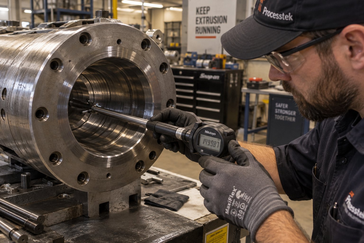
How to Measure Extruder Barrel Wear: Inspection Protocol and Techniques
Symptoms tell you something is wrong. Measurements tell you exactly how wrong — and where. Yet most guides on barrel wear stop at describing the symptoms without ever explaining how to put a number on the damage. If you want to make confident repair-or-replace decisions instead of guessing, you need a repeatable extruder barrel bore gauge measurement procedure, a standardized recording format, and the skill to read what the data is telling you.
The process is not complicated, but it demands discipline. Skipping steps, using the wrong tools, or measuring a dirty barrel will give you numbers that are worse than useless — they will give you false confidence.
Step-by-Step Bore Gauge Measurement Procedure
Before anything else, you need to choose the right measurement tool. Three common options exist, each with trade-offs:
| Tool Type | Accuracy | Ease of Use | Cost | Best For |
|---|---|---|---|---|
| Telescoping bore gauge (with external micrometer) | Moderate (operator-dependent) | Moderate | Low | Quick field checks; budget-conscious operations |
| Dial bore gauge (2- or 3-point contact) | High (0.0005 in. resolution typical) | High | Moderate | Standard production inspections; most common choice |
| Electronic internal micrometer on sled | Very high (0.0001 in. resolution) | Moderate (requires setup) | High | Precision documentation; OEM-level inspections |
For most production environments, a quality dial bore gauge with the correct extension head matched to your barrel diameter is the practical sweet spot. OEM-level inspections often use custom electronic micrometers mounted on movable sleds that travel through the bore in controlled increments, delivering the highest precision. Either approach works — what matters is consistent technique and proper calibration.
Here is the complete walkthrough, from preparation through final documentation:
- Remove the screw completely. Barrel measurements taken with the screw in place are meaningless. Pull the screw and set it aside for its own separate inspection.
- Clean the barrel bore thoroughly. Use a wire brush that fits snugly inside the bore, followed by copper gauze to remove residual polymer without scratching the liner surface. A bore gauge inserted into a barrel that still contains plastic can damage the precision measuring head and produce false readings. Do this while the barrel is still warm for easier cleaning.
- Allow the barrel to cool to ambient temperature. Thermal expansion at operating temperatures will give you an artificially large bore reading. All measurements must be taken at room temperature for valid comparison against OEM specifications.
- Record the barrel's OEM specifications. Document the original nominal bore diameter and the manufacturer's stated tolerance — typically the nominal diameter plus 0.001 inch oversize. This is your baseline.
- Calibrate the bore gauge. Set your gauge using a micrometer or ring gauge calibrated to the original barrel bore diameter plus the OEM tolerance (e.g., for a 3.500-inch nominal bore, set to 3.501 inches). Adjust the dial to zero at this dimension and repeat the calibration step to confirm accuracy. Any deviation on the dial from this point forward represents wear beyond specification.
- Establish measurement locations. Plan your measurement points along the barrel length. The standard interval is every 1 to 2 L/D (length-to-diameter ratios), which translates to roughly every 2 to 8 inches depending on barrel size. Add extra measurement points at the feed throat area, throughout the compression zone, and at any location where you suspect accelerated damage. Mark your push rod or extension tube in equal increments so you can track position precisely.
- Insert the gauge from the discharge end. Slide the bore gauge in slowly from the open end of the barrel. Never jerk, force, or rapidly push the gauge — doing so risks damaging the measuring head and produces inaccurate readings. Do not apply oil to either the gauge or the barrel bore.
- Take readings at each station. At every marked position, gently rock the gauge to find the true maximum diameter reading. Record the value. For barrels still mounted on the machine, do not measure behind the feed port — the measuring head can drop into the port opening and suffer serious damage. Leave a 2-inch gap before reaching the feed port position.
- Take readings in two perpendicular planes. At each axial position, measure both the vertical and horizontal diameters. If these two readings differ significantly — more than 0.001 to 0.002 inches — you are looking at asymmetric or ovalized wear, which points to alignment problems or thermal bowing rather than uniform abrasive degradation.
- Record all data on a barrel wear profile chart. Plot bore diameter (y-axis) against axial position along the barrel length (x-axis). This creates a visual wear map showing exactly where the bore has enlarged and by how much. Overlay the OEM nominal diameter and maximum allowable tolerance as reference lines.
Never put a bore gauge into a hot barrel or a bore containing residual plastic. Both conditions will damage precision instruments and produce unreliable data that leads to wrong decisions.
Interpreting Wear Profiles and Detecting Misalignment
A completed barrel wear profile chart is far more informative than any single measurement. The shape of the wear curve — not just the peak value — tells you what is happening inside the machine.
Here is what to look for when reading the profile:
- Localized peak in the compression zone. This is the most common pattern for abrasive wear. The bore enlargement spikes in the transition section where partially melted material under high pressure grinds against the wall, then tapers off in the metering section. It indicates normal abrasive wear driven by fillers or high compression ratios.
- Distributed, gradual enlargement across the full length. When the entire bore shows a uniform increase beyond tolerance, the barrel has experienced widespread abrasive degradation — typical of heavily filled compounds that maintain abrasive contact from feed to discharge.
- Pitting or roughness concentrated in the metering zone. This pattern points to corrosive attack from chemically aggressive resins. The bore diameter increase may be modest, but the surface quality is severely compromised.
- Asymmetric wear — different readings in vertical vs. horizontal planes. This is the critical flag for barrel alignment verification in a single screw extruder. When one side of the bore shows significantly more wear than the other, the screw has been riding against that wall due to misalignment, inadequate support, or thermal bowing.
Barrel-to-gearbox misalignment is a persistent issue for long single screw extruders, where the barrel may span 8 to 12 feet or more between the gearbox flange and the discharge end. Alignment should be verified whenever a barrel is removed or changed, if the foundation shifts, or if barrel supports move. The front barrel support contact points must be well lubricated with high-temperature silicone grease — or fitted with brazed brass tips — to allow the barrel to expand freely during heat-up without binding and warping.
Thermal bowing is equally damaging and harder to spot. When one or more barrel heater bands fail or lose efficiency, that section heats unevenly. The hotter side expands more than the cooler side, bending the barrel like a bow and forcing the screw into the concave wall. The result is a unilateral wear stripe that progresses rapidly because the deflection increases contact forces well beyond what normal processing generates. Monitoring barrel temperature uniformity with an infrared thermometer during operation can catch this condition before it carves a permanent signature into the bore.
Perhaps the most valuable insight comes from comparing successive inspection records taken at consistent intervals. A barrel in its steady-state wear period will show slow, linear increases of a few tenths of a thousandth per measurement cycle. When those increments suddenly double or triple between inspections, the barrel has likely transitioned into an accelerated wear phase — the hardened liner surface has been penetrated, and the softer base material underneath is being consumed far more rapidly. Catching that inflection point early is the difference between a planned maintenance event and an emergency shutdown that disrupts production for days.
Wear Progression Timeline and Barrel Metallurgy Options
Successive bore measurements give you a snapshot of where the barrel stands right now. But a single snapshot does not tell you how fast things are changing or — more critically — whether the barrel is about to enter a rapid decline. Plotting those measurements over time reveals something far more useful: the extruder barrel wear progression phases that every barrel moves through during its service life. Recognizing which phase your barrel occupies determines whether you have months of useful life remaining or weeks.
Understanding the Three Phases of Barrel Wear Progression
Think of barrel wear not as a steady, linear slide toward failure but as a three-act story with a dramatically different pace in each act.
Phase 1 — Break-in. A brand-new barrel is not perfectly smooth at the microscopic level. Machining and honing leave tiny high spots, surface irregularities, and asperities that contact the screw flight tips immediately upon startup. During the first few hundred operating hours, these high points wear away quickly, and the bore diameter increases at a rate that can look alarming if you are measuring closely. Do not panic. This initial settling period is normal — the surface is conforming to its working geometry. Once those irregularities are gone, the wear rate drops sharply and stabilizes.
Phase 2 — Steady-state wear. This is the productive heart of the barrel's service life. Wear progresses slowly and linearly, driven by whichever mechanism dominates your application — abrasive, corrosive, or adhesive. Bore measurements taken at regular intervals show small, consistent increments: perhaps a few tenths of a thousandth of an inch per measurement cycle. A well-matched barrel liner processing moderately filled compounds can remain in this phase for years. The key word is predictable. You can forecast when the barrel will approach its tolerance limit and plan maintenance accordingly.
Phase 3 — Accelerated end-of-life. This is where the story turns dangerous. Every hardened barrel surface — whether nitrided or bimetallic — has a finite depth of wear-resistant material. A nitrided barrel offers roughly 0.4 to 0.6 mm of hardened case. A bimetallic liner extends 1.5 to 3.0 mm deep. Once abrasive or corrosive attack penetrates through that protective layer and exposes the softer base steel underneath, the wear rate does not just increase — it compounds exponentially. The soft substrate erodes many times faster than the hardened surface above it, and every thousandth of an inch lost accelerates the damage further because leakage flow increases, contact forces rise, and filler particles now grind against unprotected metal.
The transition from steady-state to accelerated wear is the single most critical inflection point in barrel life. Catching it early — through consistent bore measurement tracking — is the difference between a planned barrel change and an emergency shutdown.
How do you spot the transition? Look at your bore measurement trend data. During steady-state operation, the incremental increase between inspections stays roughly constant — say, 0.0002 inches every six months. When that increment suddenly doubles or triples between consecutive inspections, the hardened layer has been breached. The barrel has entered Phase 3, and every hour of continued operation consumes the remaining base material at an accelerating rate. Immediate action — whether repair, restoration, or replacement — is not optional at this point. It is a financial imperative.
This three-phase pattern also explains why bore measurements taken in isolation can be misleading. A barrel showing 0.006 inches of total wear might seem acceptable — until you realize the last 0.003 inches accumulated in just three months instead of the previous eighteen. The absolute number matters less than the rate of change.
Barrel Liner Materials and Metallurgy Comparison
The phase in which your barrel spends most of its operational life — and how long it stays in the productive steady-state period — depends heavily on what the bore surface is made of. Barrel liner metallurgy is where engineering decisions made at the time of purchase pay off (or fail) thousands of hours later. Yet most discussions of barrel liners stop at "nitrided" versus "bimetallic" without explaining the distinct alloy families within each category, their hardness characteristics, or which wear mechanisms they actually resist.
The bimetallic barrel liner material comparison below breaks this down into actionable detail. Use it alongside your polymer-to-wear-type mapping from the earlier section to match liner metallurgy to your specific application.
| Material Type | Hardness Range (HRC) | Primary Wear Resistance | Best-Suited Applications | Relative Cost | Expected Wear Life vs. Nitrided Baseline |
|---|---|---|---|---|---|
| Nitrided steel (38CrMoAlA / Nitralloy 135M) | 65-70 HRC surface (thin case: 0.4-0.6 mm) | Moderate abrasive; moderate corrosive | Unfilled commodity polyolefins, standard PVC at moderate output, low-filler compounds | 1.0x (baseline) | 1.0x (baseline) |
| Bimetallic — Iron-boron alloy (Fe-B, Fe-Cr-B) | 58-65 HRC (liner depth: 1.5-3.0 mm) | Strong abrasive; low corrosive | Mineral-filled polyolefins (CaCO3, talc), moderately filled compounds, general compounding | 1.8-2.5x | 3-5x |
| Bimetallic — Nickel-boron alloy (Ni-Cr-B-W) | 60-65 HRC (liner depth: 1.5-3.0 mm) | Good abrasive; excellent corrosive | PVC, CPVC, halogenated flame retardants, fluoropolymers, chemically aggressive compounds | 2.5-3.5x | 4-6x |
| Bimetallic — Tungsten carbide composite (WC in Ni/Co matrix) | 65-70 HRC (liner depth: 1.5-3.0 mm) | Extreme abrasive; low to moderate corrosive | High glass-fiber content (30%+ GF), heavily mineral-filled engineering plastics, recycled compounds with contaminants | 3.0-5.0x | 5-8x |
| Cobalt-based alloy (Stellite family) | 40-55 HRC (retains hardness above 400°C) | Good abrasive; good corrosive; excellent thermal stability | High-temperature engineering polymers (PEEK, PPS, PEI) processed above 380°C | 3.5-5.0x | 4-7x |
| HVOF tungsten carbide spray coating (WC-Co / WC-CrC) | 70-75 HRC (coating depth: 0.2-0.5 mm) | Extreme abrasive; low corrosive | Extreme abrasion applications; localized zone protection; screw flight hardfacing | 2.0-4.0x | 2-4x (limited by coating thickness) |
Several critical insights emerge from this barrel liner hardness wear resistance chart. First, notice that the nitrided barrel's surface hardness — 65 to 70 HRC — actually exceeds the hardness of most bimetallic liners. Sounds counterintuitive, right? The difference is depth. A nitrided case is a thin shell of hardened material sitting on top of soft base steel, with 5 to 6 times less effective wear depth than a bimetallic liner. Once breached, the barrel crashes directly into Phase 3 accelerated wear with no buffer. A bimetallic liner may be slightly softer on the surface, but it offers millimeters of homogeneous wear-resistant alloy underneath — keeping the barrel in steady-state Phase 2 for far longer.
Second, the choice between nitrided vs bimetallic extruder barrel liners is not always about picking the "better" option. For clean, unfilled polyolefin extrusion, a nitrided barrel can deliver five years or more of reliable service at roughly half the cost of a bimetallic unit. Over-specifying a tungsten carbide bimetallic liner for a plant running virgin HDPE pipe is wasted capital with no operational return. The right liner is the one matched to your dominant wear mechanism and filler loading — nothing more, nothing less.
Third, the alloy family within the bimetallic category matters enormously. An iron-boron liner handles calcium carbonate abrasion effectively, but it will corrode rapidly if you switch to PVC. A nickel-boron liner resists PVC's hydrochloric acid attack beautifully, but it may not survive the mechanical punishment of 40% glass-fiber-filled nylon. Tungsten carbide composites dominate the extreme abrasion end of the spectrum; research published in Wear found WC-based overlays outperforming plain carbon steel by a factor of 21 in erosion-corrosion resistance. But they carry the highest cost and can be more brittle under impact loads or thermal shock.
Cobalt-based alloys — the Stellite family — occupy a specialized niche. Their standout property is thermal stability: they retain hardness above 400°C, where nickel and iron alloys begin softening. If you process PEEK, PPS, or other high-temperature engineering polymers, cobalt-based liners are often the only viable long-term solution.
The practical takeaway? Match the liner's wear architecture to the threat your polymer creates. An abrasion-dominant application needs depth and hardness — iron-boron or tungsten carbide. A corrosion-dominant application needs chemical resistance — nickel-boron. A high-temperature application needs thermal stability — cobalt-based. And a clean, unfilled application may need nothing more than a well-made nitrided barrel that does the job at lower cost.
Knowing what your barrel is made of — and how far along the wear progression timeline it has traveled — puts you in a strong position to answer the next practical question: when the numbers say the barrel needs attention, should you repair it or replace it entirely?
When to Repair and When to Replace a Worn Extruder Barrel
Your bore measurements confirm the barrel is worn beyond tolerance. The wear profile chart shows exactly where the damage sits and how fast it is progressing. The liner metallurgy section told you what the barrel is made of and how deep its protective layer runs. The natural next question — the one that lands on every maintenance manager's desk — is straightforward: do you repair this barrel, or do you buy a new one?
It sounds like a binary choice. In practice, the extruder barrel repair vs replace decision involves a spectrum of worn extruder barrel repair options between those two extremes, and picking the right one depends on factors that extend well beyond the bore gauge reading alone.
Available Barrel Repair and Restoration Methods
Three primary restoration strategies exist, each suited to a different damage profile and budget scenario.
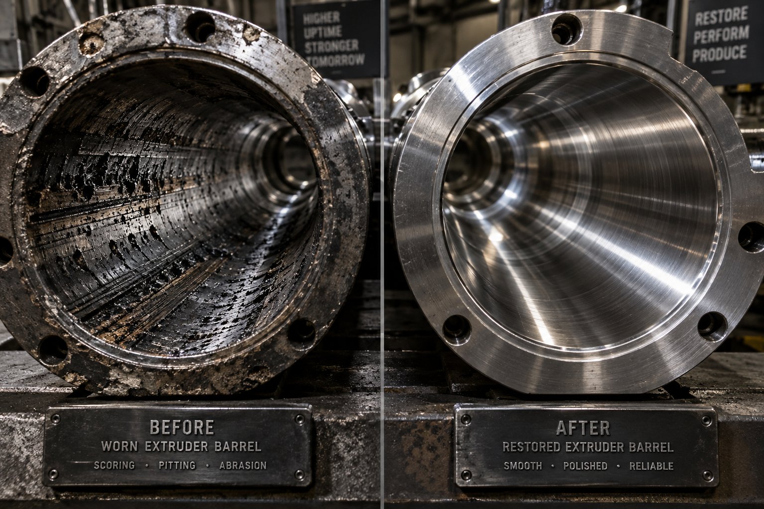
Honing. This is the lightest intervention. A precision honing tool is run through the bore to restore surface finish — removing roughness, pitting, and minor surface irregularities — without significantly changing the bore diameter. Honing works best when the bore is still within or marginally outside its tolerance window and the primary issue is surface degradation (corrosive pitting, micro-scoring) rather than dimensional enlargement. It is fast, relatively inexpensive, and can be performed without removing the barrel from the machine in some configurations. However, honing removes material rather than adding it, so it only makes sense when the bore has room to grow slightly without exceeding the maximum allowable clearance.
Resleeving or relining. When bore enlargement has progressed well beyond tolerance, barrel relining offers a full-depth restoration. The process involves boring out the worn inner surface — typically to about 1 inch larger than the original bore — then installing a new bimetallic liner with tightly controlled wall thickness. The liner is secured through a controlled heat-shrink interference fit that produces the necessary contact pressure and concentricity without welds or uneven stresses. Final machining and polishing restore the bore to OEM geometry and surface finish. This approach preserves the original barrel body, including all cooling jackets, ports, and mounting interfaces, while replacing the worn contact surface entirely. For barrel resleeving and relining cost comparison purposes, repair typically reduces expenditure by roughly 25 to 50 percent compared with purchasing a replacement — and savings increase with barrel complexity and size. Injection molding barrels, where wear often concentrates near the discharge end, are particularly strong candidates because a short sleeve at the check-ring end can restore bore geometry and sealing without relining the entire length.
Alloy spray welding and wear-resistant surface coatings. This method bridges the gap between light surface restoration and full relining. A high-performance alloy is heated to a molten or semi-molten state and deposited onto the worn bore surface, building it back up to original or improved dimensions. A dual-alloy approach — using one composition for substrate adhesion and another for the working surface — allows the coating to be tailored to the specific wear mechanism. Specialized service providers like NANHAIYA offer alloy spray welding barrel restoration that can rebuild worn surfaces and apply coatings with enhanced abrasion or corrosion resistance matched to the application. The process involves surface preparation, controlled preheating, precision alloy application, gradual cooling, CNC grinding to dimensional tolerance, and final inspection including hardness testing. Coating thickness typically ranges from 0.5 to 3 mm, making it a viable option for barrels that have lost meaningful bore diameter but still retain structural integrity in the barrel body. The cost is significantly less than full replacement while restoring performance characteristics that may actually exceed the original specification — particularly when the original liner was a standard nitrided surface and the spray-welded coating upgrades it to a higher-performing alloy.
Decision Criteria for Repair vs. Full Replacement
With three repair paths and the replacement option all on the table, how do you choose? The decision is not purely about cost — it is about matching the intervention to the barrel's actual condition, remaining useful life, and your production constraints. Walk through the following criteria in sequence:
- Current bore diameter relative to original specification and maximum allowable tolerance. As a general benchmark, when bore wear reaches about 0.020 inches, it is prudent to consider repair or replacement. For high-precision applications, the threshold may be as low as 0.003 inches. Extrusion barrels processing thick materials like rubber may tolerate wear up to 0.100 inches. Where your barrel sits within this range determines whether honing, relining, spray welding, or replacement is appropriate.
- Whether wear is localized or distributed along the barrel length. Localized wear — a compression zone hot spot or feed throat bell-mouthing — is an ideal candidate for targeted repair such as alloy spray welding or a partial sleeve. Distributed wear spanning the full barrel length often makes full relining or replacement more cost-effective because patchwork repairs along the entire bore quickly approach the cost of a comprehensive solution.
- Remaining structural integrity of the barrel body. Relining and spray welding both depend on a sound barrel shell. If the outer body shows cracking, warping, corrosion damage to cooling channels, or compromised port geometry, no amount of bore restoration will produce a reliable result. A structurally compromised shell means replacement is the only safe path.
- Cost of repair vs. replacement relative to barrel age and expected remaining service life. A relatively new barrel with a sound body and localized wear is a strong repair candidate — the 25 to 50 percent cost savings over replacement delivers clear ROI. An aging barrel that has already been relined once, with a body approaching its metallurgical fatigue limit, may not justify a second investment in repair when the body itself has limited remaining life.
- Opportunity to upgrade liner metallurgy during repair. Repair is not just about restoring the original condition — it is a chance to improve it. If your wear analysis reveals that the original nitrided liner was underspecified for your polymer, relining with a bimetallic insert or applying a spray-welded alloy coating matched to your dominant wear mechanism can deliver substantially longer service life from the rebuilt barrel than the original ever provided.
- Production urgency and acceptable downtime window. Relining requires removing the barrel, boring it out, manufacturing a precision liner, heat-shrinking the assembly, and final machining — a process that can take weeks. Alloy spray welding may offer a faster turnaround depending on part size and repair scope. A new barrel ordered from stock ships on the manufacturer's timeline. If your line is down and every day costs tens of thousands in lost production, the fastest available option may override the cheapest one.
One common mistake is treating this as a one-time decision. In reality, the repair-vs-replace calculation should be revisited at every inspection interval as new bore data comes in. A barrel that justified repair six months ago may have crossed into accelerated Phase 3 wear since then, shifting the economics decisively toward replacement. Conversely, catching wear early — before the hardened layer is breached — opens the door to cost-effective surface restoration that extends useful life by years rather than months.
The smartest operators build this decision framework into their maintenance planning before the barrel reaches a crisis point. That proactive mindset — inspecting regularly, tracking wear trends, and acting at the right moment — is exactly what separates plants that manage barrel wear from plants that are managed by it. And it leads directly to the final piece of the puzzle: a structured preventive maintenance strategy that keeps barrels in their productive steady-state phase for as long as possible.
Preventive Maintenance Strategies to Extend Barrel Life
Managing barrel wear reactively — waiting until output drops, scrap spikes, or a bore gauge reading shocks you into action — is the most expensive approach there is. Every chapter of this article has reinforced one idea: the earlier you detect clearance changes, the more options you have and the less they cost. A structured extruder barrel preventive maintenance schedule turns that principle into a repeatable system, ensuring your barrels stay in the productive steady-state wear phase for as long as physically possible.
The challenge is that not every extrusion line faces the same wear severity. A plant running clean LDPE film does not need the same inspection cadence as one compounding 40% glass-filled nylon. Matching your barrel inspection interval to the aggressiveness of the polymers you process is what separates a maintenance plan that works from one that is either wasteful or dangerously inadequate.
Inspection Interval Matrix by Processing Severity
The following matrix provides recommended inspection frequencies based on the dominant wear severity of your processing category. Adjust these intervals based on your own bore measurement trend data — if wear is progressing faster than expected, tighten the schedule accordingly.
| Processing Category | Example Materials | Bore Measurement Frequency | Visual Inspection Interval | Alignment Verification Schedule |
|---|---|---|---|---|
| Unfilled commodity resins | HDPE, LDPE, LLDPE, PP homopolymer, GPPS | Every 12-18 months | Every 6 months | Annually and after any barrel removal |
| Moderately filled compounds | PP with 10-20% CaCO3, talc-filled PE, low-fill masterbatch | Every 6-12 months | Every 3-6 months | Every 12 months and after thermal events |
| Highly filled engineering plastics | PA6-GF30, PA66-GF33, PBT-GF30, 30%+ mineral-filled compounds | Every 3-6 months | Monthly | Every 6 months and after any screw change |
| Corrosive specialty polymers | Rigid PVC, CPVC, PVDF, FEP, halogenated flame-retardant grades | Every 3-6 months | Monthly | Every 6 months and after extended shutdowns |
| Combined abrasive and corrosive | Wood-plastic composites, FR-filled nylons, recycled compounds with contaminants | Every 3-4 months | Monthly | Every 6 months minimum |
Notice that the barrel inspection interval for filled polymers is two to four times more frequent than for clean commodity resins. That difference reflects real-world wear rates — a barrel running glass-filled nylon can consume its entire steady-state wear budget in the same time a clean polyolefin barrel barely moves the needle. If you process multiple resin families on the same line, default to the schedule for the most aggressive material in your rotation.
Barrel Care Best Practices for Maximum Service Life
Scheduled measurements catch wear after it happens. The best extruder barrel care best practices also reduce the rate at which wear accumulates in the first place. Think of these as the daily and weekly habits that compound over thousands of operating hours:
- Optimize purge compound selection for your resin family. A proper purge procedure removes degraded polymer, filler buildup, and corrosive residue from the barrel bore before it can accelerate surface damage. For standard polyolefin and styrenic applications, a two-step purge using high-viscosity HDPE followed by cast acrylic is an effective protocol for scheduled maintenance. Run the HDPE purge at 25 to 40 percent of normal operating speed to scour flow surfaces, then follow with cast acrylic at low RPM (5-20 RPM) in an open-discharge configuration to clean the screw and barrel thoroughly. For high-temperature polymers like PEEK or PPS, standard purge compounds are insufficient — consult specialty purge resin suppliers for formulations rated to your processing temperature range.
- Maintain proper barrel support and verify alignment after every thermal cycle. Long single screw extruders are particularly vulnerable to thermal bowing and misalignment-driven unilateral wear. Ensure front barrel support contact points are lubricated with high-temperature silicone grease or fitted with low-friction brass tips so the barrel can expand freely during heat-up. After any barrel removal, reinstallation, or foundation work, recheck alignment before resuming production.
- Control screw speed and back pressure within manufacturer-recommended ranges. Running abrasive compounds at excessive RPM does not just increase wear proportionally — it can accelerate damage exponentially. Maximize throughput through optimized screw design and temperature profiling rather than brute-force speed increases. Keep back pressure within the range your screw and barrel combination was designed for to avoid solids wedging and unnecessary contact forces.
- Monitor barrel temperature uniformity to detect localized issues early. Use an infrared thermometer or thermal imaging camera to check barrel surface temperatures at regular intervals during operation. A cold spot may indicate a failed heater band; a hot spot may signal worn insulation, a failed thermocouple, or — critically — a section of barrel where the liner has thinned and thermal transfer characteristics have changed. Uneven heating accelerates both thermal bowing and localized wear.
- Track and trend your bore measurement data over time. A single measurement is a data point. A series of measurements taken at consistent intervals is a trend — and the trend is what tells you whether your barrel is in steady-state Phase 2 or sliding into the accelerated Phase 3 decline. Maintain a barrel history log for every machine, recording bore profiles, dates, operating hours, and the resins processed since the last measurement.
The operators who get the most life from their barrels are not the ones with the most expensive liners or the newest equipment. They are the ones who measure consistently, act on the data early, and treat barrel wear as a manageable variable rather than an inevitable cost. Proactive barrel wear restoration — catching bore enlargement while it is still in the steady-state phase and addressing it before the hardened surface layer is breached — can extend service life by years and avoid the steep costs of emergency replacements. Surface treatment services such as NANHAIYA's alloy spray welding allow operators to rebuild worn barrel surfaces and apply wear-resistant coatings matched to their specific polymer and wear mechanism, restoring performance before reaching the costly accelerated wear phase. When integrated into a disciplined inspection and maintenance program, this kind of proactive restoration transforms barrel management from a reactive expense into a predictable, optimized line item — one that protects both equipment life and production profitability over the long term.
Frequently Asked Questions About Single Screw Extruder Barrel Wear
1. How do I know if my extruder barrel is worn?
Common signs include declining output at constant screw speed, rising melt temperature without heater changes, output surging or pulsation, increased energy consumption per kilogram, dimensional instability in finished products, and gels or black specks in the extrudate. A throughput reduction of 15% or more on a standard capacity test strongly indicates significant barrel wear. The definitive confirmation requires pulling the screw and taking bore gauge measurements at regular intervals along the barrel length, comparing readings against original OEM specifications.
2. What causes barrel wear in a single screw extruder?
Three primary mechanisms drive barrel degradation. Abrasive wear results from hard particles like glass fibers, calcium carbonate, or mineral fillers scoring the bore surface under pressure. Corrosive wear occurs when chemically aggressive polymers such as PVC or fluoropolymers release acids (hydrochloric or hydrofluoric acid) that chemically attack barrel metallurgy. Adhesive wear happens when the polymer film between screw flights and barrel wall is lost, causing metal-to-metal galling. In practice, these mechanisms often act together — corrosion weakens the surface, making it easier for abrasion to strip material away, accelerating total damage beyond what either mechanism would cause alone.
3. How often should I inspect my extruder barrel for wear?
Inspection frequency depends on the materials you process. For unfilled commodity resins like HDPE or PP, bore measurements every 12 to 18 months are typically sufficient. Moderately filled compounds warrant checks every 6 to 12 months. Highly filled engineering plastics (30%+ glass fiber) and corrosive specialty polymers like PVC or fluoropolymers require bore measurements every 3 to 6 months. If you run combined abrasive-corrosive materials such as wood-plastic composites, inspect every 3 to 4 months. Always default to the schedule for the most aggressive material in your rotation.
4. Should I repair or replace a worn extruder barrel?
The decision hinges on several factors: current bore diameter versus maximum allowable tolerance, whether wear is localized or distributed, the structural integrity of the barrel body, and cost-effectiveness relative to barrel age. Options include honing for minor surface restoration, resleeving with new bimetallic liners for severe bore enlargement, and alloy spray welding to rebuild worn surfaces with wear-resistant coatings. Providers like NANHAIYA offer alloy spray welding services that can restore barrel performance and even upgrade liner metallurgy beyond original specs. Repair typically saves 25 to 50 percent versus full replacement when the barrel body remains structurally sound.
5. What barrel liner material is best for processing abrasive or corrosive polymers?
The ideal liner depends on your dominant wear mechanism. For heavily glass-filled engineering plastics, tungsten carbide composite bimetallic liners provide extreme abrasion resistance and can deliver 5 to 8 times the service life of standard nitrided steel. For corrosive resins like PVC or fluoropolymers, nickel-boron alloy bimetallic liners offer excellent chemical resistance with 4 to 6 times longer life. For combined threats such as flame-retardant compounds, choose a liner with both high hardness and a corrosion-resistant matrix. Standard nitrided barrels work well for unfilled commodity polyolefins but lack the depth of hardened material needed for aggressive applications.
Written by
Nanhaiya Technical Team
Zhoushan Nanhaiya Plastic Machinery Co., Ltd.
The Nanhaiya technical team supports screw and barrel manufacturing projects through application review, technical communication, custom manufacturing coordination, and production and quality control.
Discuss Your Application
Related Articles
More insights on screw barrel technology and plastics processing.
Blown Film Problems Decoded: What Your Bubble Is Telling You
Oct 23, 2026
Solve blown film problems from resin to roll. Learn to identify gels, gauge variation, bubble instability, die defects, and downstream failures with actionable fixes.
Read Article
WPC Decking Extrusion Line Decoded: From Raw Resin To Finished Board
Oct 23, 2026
Learn how a WPC decking extrusion line works — from raw material compounding and extruder selection to process parameters, troubleshooting defects, and line layout planning.
Read Article
Your Extruder Feeding Instability Isn't Random — Here's Why
Oct 22, 2026
Extruder feeding instability causes surging output and scrap. Learn the 6 root causes, polymer-specific fixes, wear diagnostics, and preventive protocols.
Read ArticleLooking for something else?
Search by material, symptom or product and jump straight to the relevant page.
These are navigation suggestions based on keyword matching — not a quotation, not a delivery commitment, and not a substitute for engineering review. Final specification is confirmed by our engineers against your drawings and processed material.
Need help with screw barrel selection?
Share your machine model, processed material and application. Our team can help with pricing and technical support.