


What Extruder Feeding Instability Actually Means and Why It Matters
Imagine your extrusion line is running. The hopper looks full, the screw is turning, and the motor draws current. Everything appears normal — yet output surges unpredictably, melt pressure drifts in irregular waves, and product dimensions creep outside tolerance. The extruder is not starved. It has not stopped. The problem is subtler and far more costly than a complete feed failure.
This is extruder feeding instability, and most troubleshooting guides either ignore it or lump it together with total blockage. That conflation sends process engineers down the wrong diagnostic path and keeps the real root cause hidden for weeks or months.
Defining Extruder Feeding Instability
Extruder feeding instability is the intermittent, non-uniform delivery of solid polymer into the feed zone — a condition that produces oscillating output rather than a complete stoppage. It shows up as surging discharge pressure, fluctuating motor current, and inconsistent product weight or wall thickness, all stemming from uneven solids conveyance beneath the feed throat.
Extruder feeding instability is the oscillatory fluctuation of material flow into the extruder's feed zone, causing cyclic variations in melt pressure, throughput, and product dimensions while the machine continues to operate.
The key mechanisms at work involve the balance between forwarding forces at the barrel wall and retarding forces at the screw root. As Plastics Technology explains, these forces depend mainly on surface temperatures of the screw and barrel, and to a lesser extent on screw speed and channel pressure. When that balance shifts even slightly — due to thermal drift, material variability, or mechanical wear — you'll notice the solids conveying rate begin to oscillate. The extruder keeps running, but every downstream process parameter starts to wander.
Feeding Instability vs Complete Feed Stoppage
When an extruder is not feeding at all, the diagnosis is usually straightforward. A bridge in the hopper, a stripped drive gear, or a situation where the system is unable to feed filament into the extruder points to a clear mechanical or material obstruction. Operators on desktop systems, for instance, quickly recognize when they are unable to feed filament into the extruder Bambu A1 or similar machines — the extruder motor is turning but filament is not feeding into the 3D printer, and production simply halts.
Intermittent instability is a different beast entirely. The extruder continues to produce output, so alarms may never trigger. Operators compensate by nudging screw speed, adjusting temperatures, or tweaking puller rates — often introducing new variability on top of the original problem. Meanwhile, scrap rates climb, energy consumption increases from repeated process restarts, and dimensional nonconformance quietly eats into margins. A cyclic or sawtooth pressure pattern on the trend chart is one of the clearest signatures, yet many plants never connect it to the feed zone because the line never fully stops.
Why This Problem Deserves Systematic Attention
Reactive troubleshooting — changing one temperature, swapping a screen pack, bumping screw speed — rarely resolves feeding instability because the root cause is almost never a single variable. The condition typically involves overlapping contributors: material properties interacting with thermal management, mechanical wear compounding feeder calibration drift, or screw geometry mismatched to a new resin grade.
That reality demands a structured diagnostic framework rather than a superficial checklist. The sections that follow organize every major root cause of feed zone instability into a classification system built around six engineering categories, map polymer-specific feeding behaviors, compare how the problem manifests across different extruder architectures, and lay out preventive maintenance protocols designed to catch degradation before it reaches the product. Each layer builds on the one before it, giving your team a repeatable methodology instead of another round of trial and error.
A Root-Cause Classification System for Diagnosing Feed Zone Problems
Trial-and-error adjustments treat symptoms. A classification system exposes the actual mechanism driving extruder feeding instability — and that distinction is the difference between a quick fix that holds for one shift and a permanent resolution that survives material changes, seasonal temperature swings, and production rate increases.
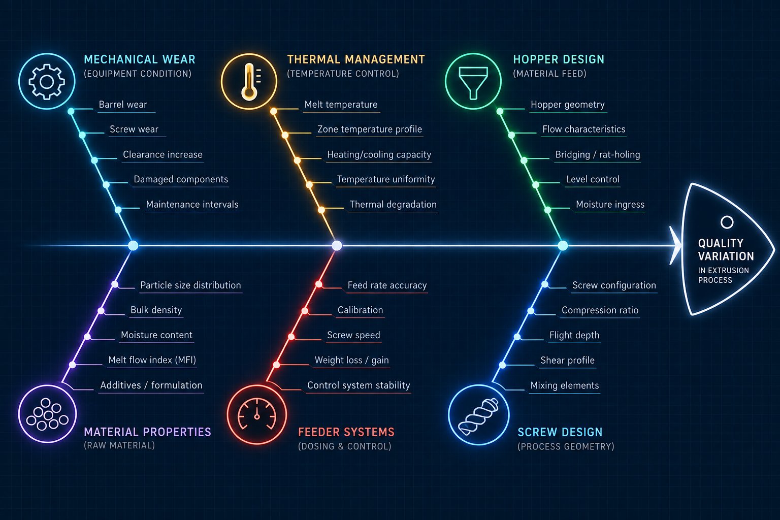
The Ishikawa (fishbone) diagram is a proven quality-improvement tool that visually maps all possible causes contributing to a specific problem. Originally developed for manufacturing root-cause analysis, this framework narrows the scope of investigation and establishes a shared understanding of where to look first. Applied to feed zone problems, it organizes the chaos of competing variables into manageable, testable branches — giving your team a common diagnostic language instead of a dozen conflicting hunches.
Six Root-Cause Categories for Feeding Instability
Every case of erratic solids conveyance in an extruder feeding system traces back to one or more of these six categories: Material Properties, Mechanical Wear, Thermal Management, Hopper and Feed Throat Design, Feeder System Calibration, and Screw/Barrel Design. Think of each category as a branch on the fishbone — and every branch contains sub-causes that interact with the others in ways that single-variable thinking will miss.
The table below maps each category to its most telling symptoms, likely root causes, and a practical first diagnostic step. Use it as a starting reference when output begins to fluctuate, rather than jumping straight to temperature adjustments or screw speed changes.
| Category | Common Symptoms | Typical Root Causes | First Diagnostic Step |
|---|---|---|---|
| Material Properties | Erratic motor load, inconsistent bulk density in the hopper, bridging or ratholing visible above the feed throat | Variable particle size distribution, low coefficient of friction, high moisture content, excessive fines or dust from regrind | Compare feed behavior across material lots; measure bulk density and moisture content of the current batch |
| Mechanical Wear | Gradually worsening output fluctuation over weeks or months, declining specific rate at the same screw speed | Worn screw flight edges increasing clearance, barrel bore enlargement, feeder agitator degradation, worn drive components | Measure screw OD and barrel ID at multiple points in the feed section; compare against OEM specifications |
| Thermal Management | Instability worsens after startup warm-up period, output degrades at higher throughput, feed casing feels hot to the touch | Inadequate feed throat cooling, scale buildup in cooling channels, failed thermocouple, screw running too hot in the solids conveying zone | Check feed casing temperature by hand; verify cooling water flow rate and inlet/outlet temperature differential |
| Hopper and Feed Throat Design | Material hang-ups, inconsistent flow from the hopper, surging that correlates with hopper level changes | Improper hopper geometry for the resin's flow angle, feed throat bore mismatch, absence of vibration or agitation for difficult-flowing materials | Observe material flow pattern in the hopper during operation; check for bridging or channeling at the transition to the feed throat |
| Feeder System Calibration | Pressure cycling at repeatable intervals matching feeder refill events, output dips during receiver dumps | Volumetric feeder unable to compensate for bulk density variation, gravimetric feeder with drifting load cells, refill algorithm causing feed interruptions | Trend feeder actual rate versus target rate; mark every refill event and compare timing to downstream pressure cycles |
| Screw/Barrel Design | Instability appears only at certain throughput ranges, poor performance with specific resin families, surging that persists regardless of temperature or feeder adjustments | Feed section channel depth mismatched to material bulk density, incorrect compression ratio, smooth bore used where grooved feed barrel is needed, insufficient conveying pitch | Review screw geometry specifications against the resin manufacturer's processing recommendations; evaluate whether the extruder feed barrel design suits the polymer being run |
Each row in this table represents a distinct diagnostic pathway. A feeder extruder configuration experiencing cyclic surging that aligns perfectly with receiver dump timing, for example, points directly to the Feeder System Calibration branch — not to thermal management or screw wear. That specificity saves hours of misdirected troubleshooting.
How to Use This Framework for Systematic Diagnosis
Identifying the symptom pattern is your entry point. The shape of the instability tells you where to start looking. Three distinct patterns dominate feed zone problems, and each one narrows the field differently:
- Cyclic surging — a repeating oscillation with a measurable period. This pattern frequently correlates with feeder refill events, receiver dump cycles, or thermal control loops that hunt around setpoint. As Gauge Advisor's diagnostic matrix highlights, the cycle time versus refill timing is one of the most revealing correlations to check.
- Random fluctuation — irregular, non-repeating output variation with no consistent period. This points toward material-driven causes such as inconsistent bulk density, contamination, intermittent bridging, or agglomerate passage through the extruder feeder. Random spikes in pressure can also indicate instrumentation issues, so verifying the signal before chasing a process ghost is essential.
- Gradual degradation — a slow, progressive worsening of output stability over days, weeks, or months. This is the hallmark of mechanical wear. Screw flight edges lose sharpness, barrel bores enlarge, and conveying efficiency quietly declines. Operators often attribute the change to material lot variation rather than recognizing the underlying hardware deterioration.
Here is the critical insight most troubleshooting approaches miss: feeding instability almost always involves multiple contributing factors from different categories. A worn screw (Mechanical Wear) processing a high-fines regrind stream (Material Properties) through a partially scaled cooling channel (Thermal Management) creates a compound problem that no single fix will resolve. The fishbone framework forces you to investigate all six branches rather than stopping at the first plausible explanation.
The diagnostic workflow, then, follows a clear sequence. Identify the symptom pattern. Trace backward through the six categories to isolate which branches are active. Test one variable at a time — giving the line enough residence time to respond — and document the result before making another adjustment. This disciplined approach, as Mark Spalding of Dow emphasizes in his work on flow surging, consistently outperforms the instinct to change three settings simultaneously.
Why Reactive Troubleshooting Falls Short
Reactive troubleshooting responds to the crisis of the moment. The line surges, an operator bumps the feed throat cooling, output stabilizes for a shift, and everyone moves on. Two weeks later, the same problem returns — slightly worse — and the cycle repeats. Sound familiar?
The classification system flips this dynamic. Instead of waiting for instability to disrupt production, you proactively monitor the conditions within each category that precede failure. Trending melt pressure coefficient of variation, tracking feeder actual-versus-target deviation, and scheduling wear measurements at defined intervals all become part of a prevention strategy rather than a reaction.
This proactive mindset matters especially for plants running abrasive compounds, recycled streams with variable bulk density, or high-throughput lines where even small conveying inconsistencies compound into significant scrap. The six-category framework provides the structure — but the real value emerges when it shapes your maintenance schedules, operator training, and KPI dashboards rather than sitting in a troubleshooting manual that only gets opened during emergencies.
With this diagnostic architecture in place, the next logical question becomes: which materials are most likely to trigger specific instability modes? The answer varies dramatically by polymer type, and that variation demands its own reference.
Material-Specific Feeding Behavior and Polymer Instability Patterns
Every polymer enters the feed zone with its own set of physical quirks — particle shape, frictional behavior, thermal sensitivity, and bulk density all conspire to create material-specific instability modes. A troubleshooting approach that treats every resin the same way will miss the mechanism hiding inside the material itself. Matching the right diagnosis to the right polymer is one of the fastest paths to stable extruder feed performance, yet surprisingly few references provide this cross-reference.
How Polymer Properties Drive Feeding Behavior
Five material properties dominate what happens in the first few diameters of the screw. Understanding each one reveals why the same extruder can run beautifully on one resin and surge badly on another — with no hardware changes in between.
- Bulk density — This is the mass per unit volume of the granulate as it sits in the hopper and flows into the screw channel. Low bulk density means fewer grams of polymer fill each screw flight per revolution, directly reducing throughput. More importantly, bulk density can vary significantly between virgin pellets and regrind of the same polymer. Research at the University of Stuttgart found that actual bulk density inside a shallow screw channel can be 15 to 32 percent lower than the standard measurement at high dumping heights — a difference large enough to throw off throughput predictions entirely.
- Particle size distribution — Uniform pellets pack predictably. Regrind, flake, and powder introduce a wide particle size distribution that changes packing behavior from one screw flight to the next. Cylindrical regrind pellets, for example, consistently yield lower bulk density and less predictable conveying than the lenticular virgin granules of the same resin. The broader the size distribution, the more susceptible the extruder feed becomes to random fluctuation.
- Coefficient of friction against steel — Solids conveying in a single-screw extruder depends on a friction differential: the polymer must grip the barrel wall more than it grips the screw root. Polyolefins like HDPE and PP have relatively low coefficients of friction against polished steel, which makes them prone to slipping and inconsistent forwarding in smooth-bore designs. Polyamide (PA), by contrast, exhibits significantly higher friction — so much so that processing PA in a helically grooved barrel can generate torque exceeding the motor's permissible power, as documented in high-speed conveying experiments.
- Moisture sensitivity — Hygroscopic resins like nylon and PET absorb atmospheric moisture that can cause pellets to stick together in the hopper or create steam pockets in the early compression zone. Even non-hygroscopic polymers can develop surface condensation during cold-weather storage, leading to intermittent bridging above the feed throat.
- Softening temperature — Polymers with low softening points, such as LDPE, risk premature melting at the barrel surface in the feed section. When pellets begin to soften before they are fully conveyed, they smear onto the screw or barrel and disrupt the solid-plug conveying mechanism. This is a particularly common instability driver in cold feed extruder configurations processing low-melting-point thermoplastics, and it also explains why feed throat cooling is critical for temperature-sensitive rubber compounds in a cold feed rubber extruder.
Each of these five properties can independently trigger a distinct instability mode. Bridging occurs when particles interlock across the hopper outlet or feed throat, usually driven by irregular particle shape or static charge. Ratholing — where material flows only from a central channel while the rest of the hopper stagnates — results from high internal friction and poor flow angles. Premature melting creates a sticky film on metal surfaces that periodically builds up and breaks free, producing cyclic surging. In practice, most problematic materials exhibit more than one of these mechanisms simultaneously.
Material-to-Instability Mapping Reference
The following table maps seven common resin families — plus the increasingly important category of recycled mixed streams — to their primary instability mechanism and the feed zone configuration that mitigates it. Use this as a starting reference when diagnosing output fluctuation on a specific material, then refine based on the particular grade and form you are running.
| Material Type | Bulk Form | Primary Instability Mechanism | Recommended Feed Zone Configuration |
|---|---|---|---|
| HDPE | Lenticular or cylindrical pellets | Low barrel friction causes slip-driven surging; lenticular pellets convey 5-8% more efficiently than cylindrical regrind due to higher packing density | Grooved feed extruder barrel with intensive feed throat cooling (below 60 °C); deeper feed channel to accommodate lower bulk density at screw-channel scale |
| LDPE | Pellets, often with anti-block additives | Premature melting from low softening temperature creates adhesive film on screw root; results in cyclic stick-slip conveying | Aggressive feed throat cooling; smooth-bore barrel preferred to avoid excessive pressure buildup; low compression ratio in early feed section |
| PP | Lenticular or spherical pellets | Low bulk density (especially cylindrical regrind) leads to inconsistent screw channel filling; relatively insensitive to back pressure changes | Groove feed extruder design for positive conveying; hopper agitation if running regrind with broad size distribution |
| PVC Dry Blend | Free-flowing powder | Powder compaction variability, ratholing in hopper, and sensitivity to moisture causing clumping in the feed throat | Smooth-bore barrel with controlled feed throat temperature; conical hopper with mass-flow geometry; forced feeding for low-bulk-density blends |
| Nylon (PA6/PA66) | Spherical or cylindrical pellets | High friction against steel generates excessive torque in grooved barrels; moisture absorption causes steam-driven surging in the compression zone | Smooth-bore barrel strongly preferred; thorough pre-drying essential (below 0.1% moisture); small spherical pellets maintain linear throughput to much higher screw speeds than cylindrical forms |
| PET | Amorphous chips or crystallized pellets | Amorphous chips have low softening temperature and tend to stick and bridge; crystallized pellets are more stable but hygroscopic | Pre-crystallization and dehumidifying dryer required; moderate feed throat cooling; smooth-bore barrel for amorphous chips to prevent excessive friction |
| PP (Recycled) | Flake, regrind, or re-pelletized | Inconsistent bulk density lot-to-lot; broad particle size distribution causes erratic packing; contamination creates intermittent bridging | Gravimetric feeding strongly recommended; grooved barrel with deeper feed channel; hopper magnets and grate screens to trap metal contamination before it reaches the screw |
| Recycled Mixed Streams | Flake, shredded, or agglomerated | Extreme bulk density variation (often 50% lower than virgin pellets); irregular particle geometry causes bridging, channeling, and inconsistent screw filling | Crammer or force-feeder required; grooved feed extruder barrel with extended feed throat; gravimetric control with fast-response refill algorithm to compensate for density swings |
A few patterns stand out from this mapping. Polyolefins — HDPE, LDPE, and PP — consistently benefit from grooved feed barrels because their low friction against steel makes them slip-prone in smooth-bore systems. Nylon and PET, with higher friction characteristics and moisture sensitivity, perform better in smooth-bore designs where friction forces are naturally higher and the risk of excessive pressure buildup is lower. Recycled and regrind materials, regardless of resin type, introduce variability that amplifies every other instability mechanism already present.
Adjusting Feed Zone Parameters by Material
Knowing which instability mechanism a polymer triggers is half the equation. The other half is configuring the feed zone to counteract it. Three parameters offer the most leverage: feed throat temperature, screw geometry in the feed section, and hopper design.
Feed throat temperature deserves the most attention because it directly controls whether the barrel surface stays below the polymer's softening point. For polyolefins processed in grooved barrels, cooling the solid conveying zone to around 60 °C has been shown to prevent premature melting while still allowing adequate friction for positive conveying. Materials with higher softening points, such as engineering resins, tolerate warmer feed throats — but you should still verify that the actual metal temperature stays well below the onset of tackiness. On the rubber side, the same principle applies to a cold feed rubber extruder, where maintaining a cooled feed section prevents premature vulcanization and ensures consistent compound delivery into the screw.
Screw geometry in the feed section shapes how reliably each flight fills with material. Deeper feed channels increase volumetric intake capacity, which helps compensate for low-bulk-density materials like regrind and recycled flake. Research confirms that lower flight pitches combined with higher flight depths reduce the rate at which specific throughput drops as screw speed increases — a direct counter to one of the most common instability drivers. Steeper compression ratios, on the other hand, force the transition from solid plug to melt earlier in the barrel. For materials that already tend toward premature melting (LDPE, amorphous PET chips), a more gradual compression ratio delays melt onset and stabilizes the extruder feed.
Hopper design is often overlooked, but it determines whether material reaches the feed throat at a consistent rate. Mass-flow hopper geometries — where all material moves simultaneously toward the outlet — prevent ratholing and first-in-last-out problems that plague funnel-flow designs. For difficult-flowing powders like PVC dry blend or low-bulk-density fluff, vibration pads or mechanical agitators break bridges before they fully form. Hopper geometry alone won't solve feeding instability driven by thermal or mechanical causes, but a poorly designed hopper can mask other improvements by introducing its own source of flow variation.
Granule shape matters more than most operators realize. Experimental data from high-speed conveying studies shows that small, spherical PA granules (averaging 12.4 mg grain mass) maintained linear throughput up to 1200 rpm in a smooth barrel, while larger cylindrical PA particles (26.7 mg) hit degressive behavior at just 300 rpm. The practical takeaway? When you switch from virgin pellets to regrind — even of the same polymer — you change the granule geometry, the bulk density, and potentially the friction characteristics all at once. Each shift compounds the risk of feed zone instability, and adjusting one feed zone parameter without considering the others rarely delivers a lasting solution.
Material properties set the stage, but the type of extruder determines how those properties interact with the machine. The same polymer that feeds beautifully in a grooved-bore single-screw system can surge unpredictably in a smooth-bore design — or vice versa — because the underlying conveying mechanisms are fundamentally different.
How Feeding Instability Differs Across Extruder Types
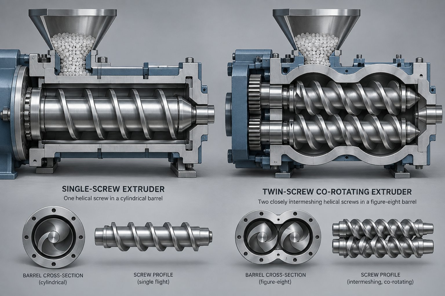
A grooved-bore single-screw extruder and a co-rotating twin-screw compounder can both display the same melt-pressure oscillation on a trend chart. The temptation is to apply the same fix to both — but the underlying conveying physics are so different that a correction that stabilizes one machine may have zero effect, or even worsen performance, on the other. Diagnosing extruder feeding instability accurately demands that you first understand how your specific machine architecture moves solids forward, because the mechanism determines where instability originates.
Single-Screw Smooth Bore vs Grooved Bore Feeding Dynamics
In a smooth-bore single-screw extruder, solids conveying relies almost entirely on a friction differential. The polymer must grip the barrel wall harder than it grips the screw root so that rotation pushes the solid plug forward rather than spinning it in place. This mechanism makes smooth-bore designs extremely sensitive to feed throat temperature. Even a few degrees of drift can shift the friction balance, causing conveying efficiency to fluctuate and output to surge. Polymers with inherently low coefficients of friction — polyolefins being the classic example — amplify this vulnerability because the friction margin is already thin.
Grooved feed barrels solve that problem through mechanical interlocking. Longitudinal or helical grooves machined into the barrel liner physically trap pellets and force them forward, creating what engineers call positive conveying. As Davis-Standard's comparative data illustrates, this approach delivers higher throughput at lower melt temperatures and significantly improved energy efficiency — particularly with high-viscosity HDPE. A direct feed extruder with grooved geometry can achieve the same output as a larger-diameter smooth-bore machine at a fraction of the energy cost.
The tradeoff? Grooved barrels generate substantially higher feed zone pressures. That pressure must be managed carefully, because excessive buildup can accelerate barrel liner wear and, in extreme cases, overload the thrust bearing. Instability in a grooved-bore system often manifests not as slip-driven surging but as pressure spikes and torque fluctuations — a completely different symptom profile that demands a different diagnostic approach.
Co-Rotating vs Counter-Rotating Twin-Screw Feeding Differences
Twin-screw extruders introduce a fundamentally different solids transport mechanism. In a co-rotating twin-screw machine, the two screws turn in the same direction with fully intermeshing, self-wiping geometry. This creates positive displacement feeding: material is transferred from one screw to the other in a figure-eight flow path, and the self-wiping action prevents accumulation and dead zones. The result is high conveying efficiency, uniform residence time distribution, and strong self-cleaning performance.
These characteristics reduce some classic instability modes — bridging in the feed throat and slip-driven surging are far less common on co-rotating systems. However, because co-rotating extruders typically run in starve-fed mode, they introduce a different sensitivity: the feeding instability migrates upstream to the feeder itself. Any fluctuation in the dosing rate from the extruder side feeder or main hopper feeder translates directly into output variation. A side feeder twin screw extruder adding glass fiber or mineral filler downstream compounds this sensitivity, since the main feed rate and the side feeder extruder rate must remain precisely synchronized. Even brief dosing interruptions during refill cycles create measurable throughput dips.
Counter-rotating twin-screw extruders behave differently again. The screws rotate in opposite directions, creating enclosed "C-shaped" chambers that transport material much like a gear pump. This geometry provides maximum positive displacement and very consistent conveying — traits that make counter-rotating designs the preferred choice for profile extrusion of heat-sensitive materials such as rigid PVC. However, their solids transport capacity is inherently more limited, the pressure stability of the molten material tends to be lower, and feeding instability often appears as pressure fluctuation in the barrel rather than throughput surging at the die. Counter-rotating systems also lack the aggressive self-wiping action of co-rotating designs, making them more vulnerable to material hang-up and degradation near the feed zone when processing sticky or low-melting compounds.
For operations running a dual feed extruder configuration — whether combining two material streams through a main hopper and a downstream side feeder, or blending virgin with recycled material — the interaction between feed rates adds another instability layer that pure single-stream systems never encounter.
The table below captures the key differences across four common extruder architectures. Use it as a diagnostic starting point to match observed symptoms to the most probable root causes for your specific platform.
| Extruder Type | Feed Mechanism | Primary Instability Symptoms | Most Common Root Causes | Key Diagnostic Differences |
|---|---|---|---|---|
| Single-Screw, Smooth Bore | Friction-dependent solids drag; barrel-to-polymer friction must exceed screw-to-polymer friction | Cyclic output surging, sawtooth melt pressure pattern, sensitivity to ambient and feed throat temperature changes | Feed throat temperature drift, low-friction polymer slippage, worn screw reducing friction differential, moisture on pellet surfaces | Surging period often correlates with thermal control loop response time; instability worsens with low-friction resins and disappears with high-friction materials on the same machine |
| Single-Screw, Grooved Bore | Mechanical interlocking via barrel grooves provides positive conveying independent of friction | Pressure spikes and torque fluctuation rather than output surging; potential barrel liner wear patterns | Excessive feed zone pressure from overfilling, worn groove geometry reducing interlocking effectiveness, inadequate cooling allowing pellet softening in grooves | Motor current and head pressure trends show spikes rather than sinusoidal surging; groove inspection reveals wear patterns concentrated at groove entry edges |
| Co-Rotating Twin-Screw | Self-wiping intermeshing geometry creates positive displacement; typically operated in starve-fed mode | Output dips synchronized with feeder refill events; throughput variation proportional to dosing rate fluctuation from main or side feeder | Gravimetric feeder calibration drift, inconsistent bulk density in the feed stream, side feeder dosing interruptions, poor refill algorithm timing | Instability maps to feeder events rather than extruder thermal cycles; replacing extruder components without checking feeder performance yields no improvement |
| Counter-Rotating Twin-Screw | Enclosed C-shaped chambers provide gear-pump-like positive displacement with limited self-wiping | Melt pressure fluctuation in the barrel, material hang-up and degradation near the feed zone, limited throughput ceiling | Material accumulation in low-wiping zones, feed rate exceeding limited solids transport capacity, thermal degradation of stagnant material releasing gas pockets | Pressure instability originates in the barrel rather than at the die; product discoloration or black specks accompany pressure upsets, pointing to degradation rather than conveying issues |
Choosing Diagnostic Approaches by Extruder Architecture
The critical takeaway from this comparison is straightforward: identical symptoms do not mean identical causes. Output surging on a smooth-bore single-screw machine almost always traces back to the friction-temperature interaction in the feed zone. That same surging on a co-rotating twin-screw compounder more likely originates in the feeder system — particularly if the line uses an extruder side feeder for additive dosing, where even small synchronization errors between the main feed and the side stream create periodic throughput imbalances. Kerke Extrusion Equipment's analysis of twin-screw output instability reinforces this distinction, emphasizing that the mismatch between screw speed and feeding speed is one of the most common — and most frequently overlooked — root causes on twin-screw platforms.
Applying single-screw troubleshooting logic to a twin-screw problem leads to predictable misdiagnosis. You'll check feed throat cooling, adjust barrel temperatures, and inspect screw wear — all valid steps on a single-screw machine, all largely irrelevant if the actual problem is a gravimetric feeder with drifting load cells. The reverse is equally dangerous: blaming the feeder on a smooth-bore single-screw extruder when the real issue is a thermal management problem wasting cooling water through scaled channels.
Your diagnostic approach, then, must start with the machine type. Match the symptom profile to the correct column in the table above, and you immediately eliminate half the possible root causes before pulling a single wrench. From there, the investigation can focus on the subsystem most likely responsible — which, for many plants, leads directly to two overlooked areas: feed throat cooling performance and feeder system selection.
Feed Throat Cooling and Feeder System Selection for Stable Output
Feed throat cooling and feeder system design sit at opposite ends of the extruder — one manages thermal conditions at the barrel entry, the other controls how material arrives at the screw. Yet both share a common trait: when either one drifts out of specification, the resulting instability looks almost identical on a melt pressure trend chart. Distinguishing between a cooling failure and a feeder dosing problem is one of the most underappreciated diagnostic skills in extrusion, and getting it wrong sends troubleshooting efforts in completely the wrong direction.
Diagnosing Cooling-Related Feeding Instability
The feed throat has a deceptively simple job: keep the barrel surface below the polymer's softening point so that pellets remain solid long enough to be gripped and conveyed forward. When cooling is adequate, pellets enter the screw channel as discrete solids, pack into a coherent plug, and move toward the compression zone in an orderly fashion. When cooling fails — even partially — pellets begin to soften prematurely, smear onto the barrel or screw surface, and disrupt the solid-plug conveying mechanism that drives consistent throughput.
What makes cooling-related instability tricky is its gradual onset. As Jinxin Extruder's diagnostic guide emphasizes, a line that feeds well at startup and then slowly starves often has feed-throat cooling loss at its root. The extruder runs fine for the first 30 to 60 minutes because residual cooling from shutdown keeps metal temperatures low. As the barrel heats up and conducts energy backward toward the feed throat, an underperforming cooling circuit cannot maintain the temperature differential. Output begins to fluctuate, then progressively deteriorates as throughput increases and generates more frictional heat in the feed section.
Three signature patterns distinguish cooling-related problems from other root causes:
- Gradual onset after startup — The line runs stably for a period, then instability creeps in and worsens over the next hour or two. Operators often blame the material lot rather than recognizing the thermal drift.
- Worsening with increased throughput — Higher screw speeds generate more shear heat in the feed zone. If the cooling circuit is already marginal, pushing the extruder feed rate higher overwhelms the cooling capacity and triggers surging that did not exist at lower speeds.
- Correlation with cooling water conditions — Seasonal changes in plant cooling water temperature, flow rate reductions from partially closed valves, or tower fouling all shift the thermal balance. If instability appears in summer months or after cooling system maintenance, the connection is rarely coincidental.
A systematic diagnostic approach prevents guesswork. Follow these steps in order before adjusting any process temperature:
- Verify cooling water flow rate — Confirm actual flow through the feed throat jacket using a sight-flow indicator or inline flow meter. A connected hose with no flow restriction is not the same as adequate flow. Partially clogged circuits can reduce flow by 50% or more without any visible external indication.
- Measure inlet and outlet temperature differential — A healthy feed throat cooling circuit shows a measurable temperature rise between inlet and outlet water. If the differential is near zero, the circuit is likely bypassing the jacket entirely. If the differential is excessive — more than 10-15 degrees Fahrenheit above normal — scale buildup or reduced flow is limiting heat transfer.
- Inspect for scale buildup in cooling channels — Mineral deposits accumulate inside cooling jackets over months and years, progressively insulating the metal surface from the cooling water. This degradation is invisible from outside the machine. Periodic descaling or flushing with appropriate chemical agents restores heat transfer performance.
- Verify thermocouple accuracy — A feed zone thermocouple that reads low gives the controller false confidence that temperatures are under control. Compare the thermocouple reading against a calibrated handheld probe pressed against the feed throat casing. Discrepancies of even 5-10 degrees can mask a cooling deficiency that is driving instability.
This same thermal management principle extends beyond thermoplastic extrusion. In a hot feed extruder processing pre-warmed rubber compounds, the feed section still requires precise temperature control — not to cool aggressively, but to maintain the compound within a narrow viscosity window that ensures consistent screw bite. Similarly, a hot feed rubber extruder relies on the incoming compound's temperature and plasticity being uniform; any variation in pre-warming creates the same kind of intermittent output fluctuation that cooling loss produces in thermoplastic systems. The physics differ, but the diagnostic logic is remarkably parallel.
Gravimetric vs Volumetric Feeder Selection and Impact on Stability
Imagine pouring cereal from a box into a bowl. You tilt the box at the same angle every time, but the amount that comes out depends on whether the box is full of whole flakes, half-crushed pieces, or mostly dust at the bottom. That is exactly how a volumetric feeder works — and exactly why it can amplify extruder feeding instability when material bulk density varies.
A volumetric feeder delivers a constant volume of material per unit time. Its screw, belt, or vibratory mechanism runs at a fixed speed, and the assumption is that each unit of volume contains the same mass. When processing uniform virgin pellets with stable bulk density, that assumption holds well enough. The moment you introduce regrind, recycled flake, or powder blends with variable packing characteristics, the assumption breaks down. Each screw flight of the feeder delivers a different mass, and that variation passes directly into the extruder feed zone as fluctuating solids input.
A gravimetric feeder eliminates this vulnerability by measuring actual weight loss over time using precision load cells. When bulk density drops — fewer grams per cubic centimeter of feeder volume — the control system automatically increases feeder screw speed to maintain the target mass flow rate. When density rises, it slows down. This closed-loop compensation happens continuously, in real time, smoothing out the very material variability that volumetric feeders pass through uncorrected.
The practical impact on process stability is significant. Genesis Process Solutions notes that gravimetric feeders are particularly valuable for processes requiring tight tolerances, regulatory compliance, or when handling difficult and variable materials — conditions that describe most operations where feeding instability is an active concern.
| Feature | Volumetric Feeder | Gravimetric Feeder |
|---|---|---|
| Operating Principle | Delivers constant volume per unit time; screw or belt runs at fixed speed regardless of material density | Measures weight loss over time via load cells; adjusts feeder speed in real time to maintain target mass flow |
| Best Applications | Uniform virgin pellets with consistent bulk density; single-material runs with minimal lot-to-lot variation; cost-sensitive operations with relaxed dimensional tolerances | Regrind, recycled streams, and powder blends with variable bulk density; multi-component dosing requiring precise ratios; tight-tolerance extrusion where output consistency directly affects product conformance |
| Instability Risk | High when bulk density fluctuates — every density shift passes directly into the extruder as a mass flow deviation; refill events can cause brief feed interruptions without compensation | Low under normal operation — closed-loop control compensates for density variation automatically; refill algorithms manage hopper replenishment with minimal disruption to dosing accuracy |
| Cost Consideration | Lower capital cost; simpler mechanical design; minimal maintenance and calibration requirements; lower operator training burden | Higher capital cost due to load cells, controller, and refill management system; requires periodic load cell calibration; provides measurable ROI through reduced scrap and tighter process control on variable-density materials |
The decision between these two systems is not simply a budget question — it is a process stability question. Plants running consistent virgin resin on flood-fed single-screw lines can often achieve acceptable stability with volumetric feeders, since bulk density variation is minimal and the extruder's own conveying behavior acts as a buffer. Plants running starve-fed twin-screw compounders with recycled material streams face a fundamentally different reality. On those lines, the feeder is the extruder's metering device. Every fluctuation in feeder output translates one-to-one into throughput variation, making gravimetric control not a luxury but a prerequisite for stable operation.
When Crammer Feeders and Force Feeders Become Necessary
Some materials defeat both volumetric and gravimetric feeders because the problem is not dosing accuracy — it is getting the material into the screw at all. Low-bulk-density fluff from film regrind, foam scrap, long fibers, and heavily aerated powders simply cannot flow by gravity into a standard feed throat. They bridge, float, and resist compaction in ways that no metering algorithm can fix.
A crammer feeder extruder configuration addresses this by adding a secondary auger above the feed throat that actively pushes material downward into the screw channel. As extrusion consultant Jim Frankland explains, the goal of a properly designed crammer is to deliver material to the extruder screw uniformly without generating much temperature rise or excessive pressure. The crammer auger compacts low-bulk-density material into a denser mass that the primary screw can grip and convey, effectively bridging the gap between what the material wants to do (float and bridge) and what the extruder needs it to do (fill screw flights consistently).
Designing a crammer is far from trivial. The auger must be matched to the material's flow characteristics, packing tendency, and bulk density. For higher-bulk-density materials that simply bridge or tunnel, a straight-flight auger in a cylindrical housing works well. For very low-bulk-density materials like film regrind or foam, a tapered auger that conforms to a conical hopper provides a larger initial bite and preliminary compaction before material reaches the feed throat. Frankland cautions that an over-driven crammer can cause surging as it overstuffs the feed section, leading to inconsistent output, high screw and barrel wear, drive overload, and even thrust bearing failure.
A force feeder for extruder applications operates on a similar principle but typically uses a different mechanical arrangement — often a set of counter-rotating paddles or a ram-style mechanism — to push material into the feed opening. Force feeder extruder setups are common in recycling operations handling shredded mixed waste, agricultural film, and other irregularly shaped feedstocks where even a crammer auger cannot maintain consistent intake. The key engineering constraint for any forced-feeding approach is matching the feed rate to the extruder's actual conveying capacity. Forcing material in faster than the screw can process it creates the same surging and overload problems that the force feeder was meant to solve.
Before committing to a crammer or force feeder, it is worth revisiting hopper geometry, feed throat design, and screw configuration. As Frankland advises, there are enough negative aspects to using a crammer that changes in hopper, feed-throat, and screw design should be explored first. A crammer adds mechanical complexity, maintenance requirements, and another potential source of process variation. It solves genuine material handling problems — but only when simpler approaches have been exhausted.
Cooling circuits degrade. Feeders drift. Crammers wear. Every component discussed in this section shares a common vulnerability: progressive mechanical deterioration that slowly erodes feeding stability over weeks and months, often so gradually that operators attribute the change to material variation rather than hardware condition. Recognizing that wear pattern — and knowing where to measure it — is the next critical step in eliminating output instability at its source.
Screw and Barrel Wear Patterns That Degrade Feeding Performance
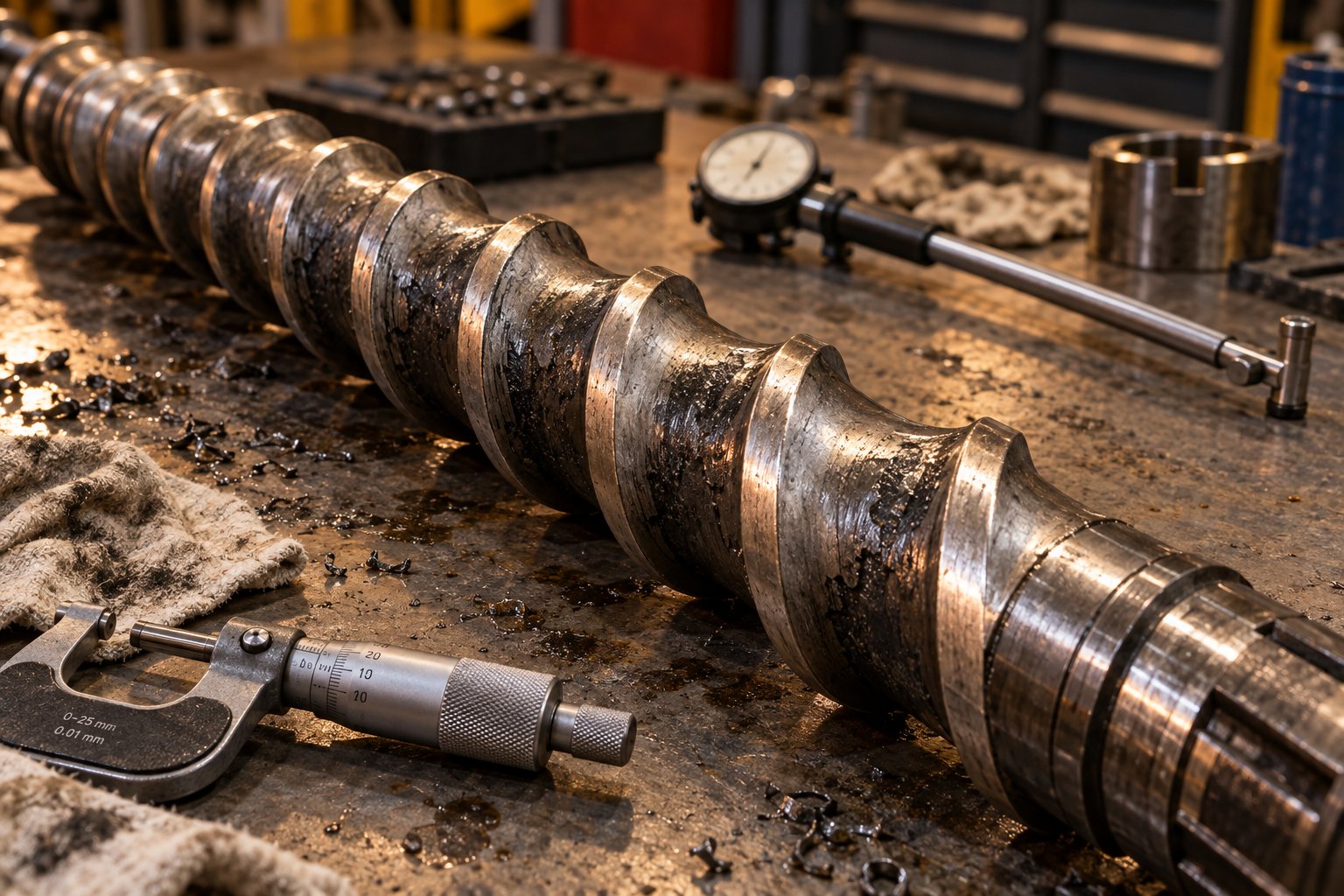
Here is the frustrating reality of mechanical wear in the feed zone: it rarely announces itself. There is no alarm, no sudden failure, no single shift where output clearly drops. Instead, the extruder feed screw gradually loses conveying efficiency over hundreds or thousands of operating hours. Flight edges round off. Barrel bores enlarge by fractions of a thousandth of an inch. Operators compensate — bumping screw speed here, nudging a temperature there — and the line keeps running. By the time someone pulls the screw for inspection, weeks or months of elevated scrap, wasted energy, and unexplained output fluctuation have already accumulated.
This slow-motion degradation is one of the most common — and most frequently misdiagnosed — drivers of extruder feeding instability. Because the change is gradual, it mimics material lot variation, seasonal temperature shifts, and a dozen other plausible explanations. Recognizing wear-driven instability for what it is requires understanding where wear concentrates, how it affects solids conveying, and what to measure during inspections.
Screw and Barrel Wear as a Progressive Instability Driver
Picture the relationship between the screw flight outer diameter and the barrel inner wall. In a new machine, the radial clearance between these surfaces is tight — typically a few thousandths of an inch, specified by the OEM for the particular screw diameter. This close tolerance is not arbitrary. It ensures that polymer pellets are gripped and pushed forward rather than tumbling backward over the flight tips. Every thousandth of an inch of additional clearance creates a leakage path where material slips rearward instead of conveying forward, directly reducing throughput consistency.
As Stephen Surley of SpiraMelt Technologies explains, the majority of screw wear occurs in high-pressure zones — particularly the transition section and last few turns of metering. However, when processing abrasive fillers such as glass fibers or calcium carbonate, significant wear develops in the feed section as well. Pressure builds against the forwarding side of each flight, and unmelted pellets provide limited lubrication compared to molten polymer downstream. The result is accelerated flight OD erosion precisely where consistent solids conveying matters most.
Three wear mechanisms work simultaneously in the feed zone:
- Abrasive wear — Hard filler particles, mineral additives, and even glass-fiber-reinforced compounds act like sandpaper against flight edges and barrel surfaces. Larger particles with sharper corners cause more aggressive material removal than smaller, rounder ones. A screw feed extruder processing 30% glass-filled nylon, for instance, will lose flight OD material several times faster than the same machine running unfilled resin.
- Adhesive wear — Metal-to-metal contact between the screw flights and barrel wall occurs when alignment is compromised, the screw is bent, or the barrel sags. Adams Engineers identifies improper screw, barrel, and drive alignment as a key contributor to adhesive wear, along with incompatible geometries that force surfaces into contact under load.
- Corrosive wear — Chemical attack from degraded resin byproducts erodes metal surfaces from within. PVC is the classic offender, releasing hydrochloric acid at elevated temperatures. As Surley notes, this acid generation leads to extreme corrosive wear on equipment, compounding any abrasive damage already present.
The performance impact follows a predictable but deceptive pattern. Minor wear produces little noticeable effect because operators can adjust machine parameters to compensate. As radial clearance increases, leakage flow over the flights grows — and with it, melt temperature rises due to excessive shear. The operator responds by increasing screw speed to maintain output, which generates even more shear heat, accelerates further wear, and creates a self-reinforcing degradation cycle. A common rule of thumb considers a flight clearance four times the original tolerance as the threshold for replacement, though resin viscosity significantly influences how much rate loss a given clearance produces. Higher-viscosity polymers like PE tolerate more clearance before output drops noticeably, while lower-viscosity resins such as PP show rate loss much sooner.
Root wear — erosion of the screw channel floor — creates a different but equally damaging instability mode. Worn root surfaces develop pockets and rough areas where polymer hangs up and degrades over time. This degraded material periodically breaks free and contaminates the melt stream, appearing as black specks, gels, or localized surging as the dislodged material disrupts the solid plug behind it.
Feed Zone Screw Element Configuration and Its Effect on Stability
Wear is not the only hardware factor that influences feed zone stability. The design of the extruder feed screws themselves — specifically the conveying element pitch, compression ratio, and flight geometry in the feed section — determines how reliably solids transport from the hopper into the compression zone.
Conveying element pitch controls the volumetric displacement per screw revolution. As NC State Extension's screw design reference explains, deeper-flight conveying elements with larger pitch — such as an SK 40/40 configuration on a twin-screw — move greater bulk volumes per revolution, which helps compensate for low-bulk-density materials. Smaller pitch elements like SE 20/20 compress material and build pressure more aggressively, but their conveying capacity is lower. The wrong pitch for a given material creates a mismatch between the rate at which material enters the screw and the rate at which it is forwarded — a direct recipe for cyclic instability.
Channel depth in the feed section sets the volumetric intake capacity. Deeper channels accept more material per flight, which benefits low-bulk-density regrind and recycled streams that do not pack tightly. The tradeoff is that deeper channels reduce the pressure gradient across each flight, potentially allowing more backward leakage — especially as wear opens up the flight-to-barrel clearance. Finding the right balance between intake capacity and pressure consistency is a design-level decision that directly influences long-term feeding stability.
Compression ratio — the ratio of feed channel depth to metering channel depth — governs how quickly the screw transitions from solid conveying to melting. A steep compression ratio forces the transition early, generating high localized pressure and shear. For materials already prone to premature softening (LDPE, amorphous PET), this early compression onset can trigger erratic melting behavior where the solid plug breaks apart unpredictably rather than melting progressively. A gentler compression ratio delays melt onset, stabilizes the solid bed, and produces more consistent pressure buildup — but at the cost of requiring a longer barrel to achieve complete melting.
In twin-screw systems, the distinction is even more granular. Conveying elements, kneading blocks, and reverse elements can be rearranged on the screw shaft to create dramatically different processing characteristics. A screw profile with aggressive kneading elements placed too close to the feed section can restrict forward flow and cause material backup, while insufficient conveying pitch upstream of the first mixing zone leads to inconsistent filling of the kneading blocks — another source of pulsating output. The critical principle, as the NC State reference emphasizes, is that no gold standard exists for screw profile design because every material exhibits unique flow properties influenced by temperature, shear rate, and extruder geometry.
Inspection Methods and Wear Measurement Protocols
Knowing that wear degrades feeding performance is only useful if you can quantify it. Subjective assessments — "the screw looks okay" — miss the incremental changes that accumulate between inspections. A structured measurement protocol, performed at regular intervals, replaces guesswork with data and catches degradation before it reaches the production floor.
- Visual inspection of flight edges — Remove the screw, clean off all residual resin, and place it on a clean, flat work surface. Examine the flight edges for rounding, chipping, and uneven wear. Adams Engineers recommends checking for pitting, cracks, and general damage during this initial visual pass. If available, roll the screw on a granite surface table and look for bowing — a bent screw accelerates adhesive wear and creates localized instability that is almost impossible to diagnose from process data alone.
- Micrometer measurement of screw OD at multiple points along the feed zone — Using a parallel test bar spanning two flights provides a reliable outer diameter reading. Measure at a minimum of three positions along the feed section: near the feed throat opening, at the midpoint of the feed zone, and at the transition to the compression section. Record each measurement to two decimal places and compare against the OEM specification. A screw OD that has decreased by more than 0.002 to 0.004 inches per side (depending on screw diameter) is approaching the replacement threshold for most resins.
- Root diameter and channel depth measurement — Measure the root diameter in both the feed and metering sections. Root wear is most severe on the forwarding side of the flights, so rotate the screw and take readings at multiple angular positions. As Surley documents, extreme root wear can wash out the sides of flights, leaving insufficient substrate to support hardfaced inlays — at which point the screw is beyond rebuilding.
- Bore gauge measurement of barrel ID — Using a telescoping bore gauge, measure the barrel internal diameter as far down each end as access permits. A barrel that has enlarged beyond 0.005 to 0.008 inches over nominal (again, depending on diameter) is losing conveying efficiency and contributing to leakage flow. Compare to SPI Dimensional Guidelines for reference on maximum acceptable wear.
- Comparison against OEM specifications and previous measurements — No single measurement tells the full story. Tracking wear progression over time reveals the rate of degradation and lets you predict when the next replacement or rebuild will be necessary. Plants that record measurements at every scheduled pullout build a wear profile for each screw and barrel combination, enabling planned replacement rather than emergency downtime.
One important nuance: feeder agitator components, hopper liners, and crammer auger flights also wear — and their degradation can mimic screw-related instability. Include these upstream components in your inspection protocol, particularly on lines processing abrasive or glass-filled compounds where every contact surface erodes simultaneously.
Quantified wear data does more than justify a rebuild or replacement purchase order. It feeds directly into a preventive maintenance strategy that catches degradation early, schedules interventions during planned downtime, and tracks KPIs that reveal emerging instability before it reaches the product — a shift from reactive firefighting to proactive process control.
Preventive Maintenance Protocols That Eliminate Feeding Instability
Wear data sitting in a filing cabinet does nothing. Wear data plugged into a living maintenance schedule — with defined intervals, measurable thresholds, and clear action triggers — transforms reactive scrambles into planned events that never reach the production floor. The difference between plants that fight extruder feeding instability month after month and plants that rarely encounter it almost always comes down to whether someone built a prevention system around the feed zone or simply waited for the next crisis to dictate the schedule.
The inspection methods and measurement protocols covered in the previous section generate the raw numbers. This section puts those numbers to work inside a structured framework designed to catch degradation early, intervene at the right moment, and track the leading indicators that predict instability before product quality suffers.
Preventive Maintenance Schedule for Feed Zone Components
A useful maintenance schedule does not try to inspect everything at the same frequency. Feed extruder parts and components wear at different rates depending on their material of construction, the abrasiveness of the resin, and total throughput volume. The table below assigns inspection intervals based on typical industrial operating conditions. Treat these as starting points — shorten intervals for lines running glass-filled compounds or recycled streams with metal contamination, and extend them for operations processing clean, unfilled polyolefins.
| Component | Inspection Interval | What to Check | Action Threshold |
|---|---|---|---|
| Feed screw (feed section flights) | Every 2,000-4,000 operating hours, or at every scheduled screw pull | Flight OD at multiple axial and clock positions; root diameter; visual inspection for rounding, chipping, or scoring on flight edges | Flight OD worn more than 0.002-0.004 inches per side below OEM spec (diameter-dependent); root wash visible on push side of flights — schedule rebuild or replacement |
| Barrel liner (feed zone bore) | Every 2,000-4,000 operating hours; coincide with screw pull | Bore ID at multiple axial positions and clock angles using telescoping bore gauge; inspect for oval wear patterns, scoring, and corrosive pitting | Bore enlarged more than 0.005-0.008 inches over nominal (diameter-dependent); oval wear exceeding 0.003 inches difference between 0-degree and 90-degree readings — plan barrel replacement or re-bore |
| Feed throat cooling channels | Monthly flow verification; quarterly thermal performance check; annual descaling | Cooling water flow rate through feed jacket; inlet-to-outlet temperature differential; visual inspection of water color and turbidity during drain | Flow rate below 75% of commissioning baseline; temperature differential exceeding 15 °F above normal; visible scale or rust particles in drained water — descale channels and flush system |
| Hopper magnets and grate screens | Every shift (magnets); weekly (grate screens) | Metal accumulation on magnets; grate screen integrity and blinding from fines or agglomerates; magnet pull strength with a test piece | Any metal fragments found — investigate upstream contamination source immediately; grate screen more than 30% blinded — clean or replace; magnet pull strength below rated specification — replace magnet |
| Feeder screws and agitators | Every 1,000-2,000 operating hours for abrasive materials; every 4,000 hours for non-abrasive pellets | Feeder screw flight condition; agitator blade shape and edge sharpness; clearance between feeder screw and housing; hopper bridge-breaker condition | Feeder screw flights visibly rounded or chipped; agitator blades bent or thinned more than 15% from original profile; increased dosing variability on gravimetric trend — replace worn components |
| Temperature sensors (feed zone thermocouples) | Quarterly calibration check; annual replacement for high-duty lines | Compare thermocouple reading against a calibrated handheld probe at the same location; check wiring and connector condition for corrosion or looseness | Deviation exceeding 5 °F from reference probe; noisy signal with erratic swings not correlated to process changes — replace thermocouple and verify wiring integrity |
Two practical notes on this schedule. First, as Jinxin Extruder's maintenance checklist emphasizes, feed throat cooling and melt pressure trend are among the highest-value daily checks because they take little time and reveal feeding loss before the line stops. Folding a 30-second feed throat temperature verification into every shift startup costs almost nothing but catches cooling circuit degradation weeks before it produces output instability. Second, plants running a cold feed rubber extruder machine or similar equipment processing abrasive compounds should cut these intervals roughly in half — the wear rate on feed extruder machine components handling filled or reinforced materials is dramatically higher than on lines running clean commodity resin.
Key Performance Indicators for Early Detection
Scheduled inspections catch hardware degradation. But what about the drift that happens between inspections? That is where continuous KPI monitoring earns its value. Trending the right process metrics over time reveals emerging instability days or weeks before it shows up as a visible defect — giving your team a window to plan corrective action rather than react to a production crisis.
- Melt pressure coefficient of variation (CoV) — This is arguably the single most sensitive indicator of feed zone health. A stable process produces melt pressure variation under ±50 PSI during steady-state operation. As predictive maintenance specialists at MachineCDN document, when melt pressure variance increases — even if the mean value remains stable — it signals that solid-bed conveying is becoming inconsistent. A melt pressure CoV trending upward over two or three consecutive measurement periods is an early warning that demands investigation, not a statistical anomaly to dismiss.
- Motor current fluctuation amplitude — Motor amperage at a fixed screw speed should be stable within a narrow band. Widening oscillation in motor current — particularly a subtle 2-5 minute cyclic pattern — often indicates solids plug breakup in the feed zone. Track the peak-to-trough amplitude over each shift and compare week to week. A 10% increase in fluctuation amplitude from baseline, as the MachineCDN threshold framework suggests, warrants an advisory alert and closer monitoring.
- Throughput deviation percentage — Compare actual output (measured by gravimetric weigh belt or product accumulation) against target rate. Healthy lines hold within ±1-2% of setpoint. Deviations exceeding ±5% that persist across multiple production runs point to conveying inconsistency rather than transient process upset. This metric is especially revealing on starve-fed twin-screw systems, where the extruder processes only what the feeder delivers — any feeder drift appears immediately in the throughput number.
- Product weight consistency trends — Downstream of the extruder, product weight or wall thickness variation integrates every upstream fluctuation into a single measurable outcome. Track the standard deviation of product weight across sample groups over weeks. A widening standard deviation — even when the mean weight remains on target — indicates growing process variability rooted in the feed zone. As screw and barrel wear progress, industry analysis confirms that dimensional tolerances widen progressively even as operators tighten setpoints, a classic data fingerprint of internal wear.
- Specific energy consumption (kWh/kg) — Specific energy normalizes power draw against throughput, filtering out the noise of speed adjustments. When this metric trends upward over weeks or months with no material or process change to explain it, the screw barrel assembly is losing efficiency. It is one of the most sensitive wear indicators available and should be logged at every scheduled production review.
None of these KPIs works in isolation. The real diagnostic power emerges when you correlate them. Imagine melt pressure CoV climbing while motor current fluctuation amplitude increases and specific energy trends upward — yet barrel zone temperatures and screw RPM remain unchanged. That convergence of signals almost certainly points to progressive screw or barrel wear rather than a material or temperature problem. Single-metric monitoring catches obvious failures. Multi-metric correlation catches the subtle, creeping degradation that causes the most cumulative damage.
Building a Feed Zone Maintenance Culture
Schedules and KPIs are tools. Their value depends entirely on whether the people running the line actually use them — and whether the data they generate informs real decisions. Building a maintenance culture around the feed zone requires three foundational practices that most plants overlook.
Document baseline performance during commissioning or after every screw/barrel replacement. This is the single most impactful step a plant can take. When a new screw and barrel go into service, run the line at standard operating conditions for two to four weeks and record every KPI listed above: melt pressure mean and CoV, motor amps at rated RPM, throughput rate, specific energy, and product dimensional data. These numbers become the reference point against which all future readings are compared. Without a baseline, you are comparing today's data to a memory — and memory is unreliable. Predictive maintenance programs built on documented baselines typically achieve 35-50% reduction in unplanned downtime within the first six months, not from complex algorithms, but from simply watching known data streams against a defined starting point.
Assign ownership of feed zone metrics to specific roles. When everyone is responsible for monitoring, no one monitors. Designate a process technician or shift lead as the owner of daily feed throat temperature checks and melt pressure trend reviews. Assign a maintenance engineer to own quarterly thermocouple calibrations and cooling channel inspections. Make the production manager accountable for reviewing KPI trends monthly and authorizing preventive interventions before thresholds are breached. This role clarity prevents the all-too-common scenario where a gradually worsening pressure trend goes unaddressed because everyone assumed someone else was watching it.
Treat screw and barrel condition as a managed asset, not a disposable part. Every feed zone component has a measurable service life that depends on what resin it processes, how many hours it runs, and how well the surrounding systems — cooling, feeders, alignment — support it. Plants that track wear progression across inspection cycles can predict replacement timing within weeks, converting a potential emergency shutdown into a planned maintenance event. For operations evaluating their current screw and barrel condition or sourcing replacement components, manufacturers like NANHAIYA provide practical technical support for feed zone component inspection, replacement specification, and troubleshooting persistent output instability — particularly valuable for recycling operations and plastic processing teams dealing with variable feedstocks that accelerate wear unpredictably.
This asset-management mindset extends beyond the screw and barrel themselves. Feed area guarding for extruder gear pump for rubber and thermoplastic lines alike should be included in the maintenance scope, since protective guarding that degrades or is removed for access and not reinstalled creates both safety hazards and environmental exposure that can accelerate component deterioration. Every element surrounding the feed zone — guards, cooling lines, sensor wiring, hopper seals — either supports stable operation or quietly undermines it.
The financial justification for this prevention-first approach becomes unmistakable when you trace what happens downstream of a neglected feed zone. A small, undetected conveying fluctuation does not stay small. It amplifies through every subsequent processing step — melt homogenization, die flow distribution, cooling, and dimensional control — compounding into scrap rates, energy waste, and customer quality complaints that dwarf the cost of the inspection and maintenance that would have prevented them.
Downstream Consequences and the True Cost of Ignoring Feed Zone Problems
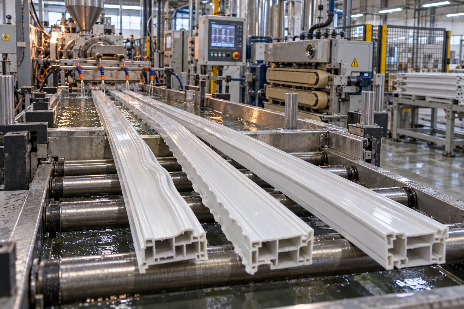
A two-percent fluctuation in solids conveying sounds harmless. It barely registers on the motor amperage display and might not even trigger a process alarm. Yet that modest oscillation does not stay at two percent. It amplifies through every downstream processing stage — melt homogenization, die flow distribution, cooling calibration, and haul-off tension — until it arrives at the product as a dimensional defect, a surface blemish, or a reject sitting in a scrap bin. Understanding this amplification chain is what separates plants that tolerate chronic waste from plants that eliminate it at the source.
How Feed Zone Fluctuations Cascade Into Product Defects
The cause-and-effect chain follows a predictable sequence, and each link magnifies the original disturbance rather than dampening it.
It starts with inconsistent solids conveying. When screw flights fill unevenly — whether due to material bridging, thermal drift, feeder dosing errors, or progressive wear — the mass flow rate entering the compression zone oscillates. That uneven solid bed produces variable melting rates, because sections of thicker solid plug require more energy to plasticize than thinner sections passing through at the same screw speed. The melt emerging from the metering zone is no longer homogeneous: it carries viscosity gradients from temperature differences and pressure waves from uneven compression.
Those viscosity gradients hit the die and create unequal flow distribution. In extruded profiles, this shows up as dimensional inconsistency — a window frame section that is 0.3 mm thicker on one side for ten seconds, then 0.2 mm thinner for the next five. In blown film, wall thickness variation produces bands of weak spots that compromise bag strength and seal integrity. In pipe extrusion, even slight pressure fluctuations alter wall thickness, roundness, and inner diameter — potentially compromising sealing and functionality in supply lines, heating tubes, or medical tubing.
Surface defects compound the dimensional problems. Melt fracture — the rough, sharkskin-like surface that appears when wall shear stress at the die lip exceeds a critical threshold — becomes intermittent rather than constant. When melt pressure surges periodically, the shear stress cycles above and below the melt fracture threshold, producing alternating bands of smooth and rough surface that make the defect harder to diagnose than a steady-state surface problem. Operators chasing this intermittent sharkskin often adjust die temperatures or lip gaps, treating the symptom at the die rather than the cause in the feed zone.
The amplification factor is significant. A throughput fluctuation of just a few percent at the feed zone can produce dimensional variation of five to ten percent at the product — enough to push an extruder not feeding filament at a consistent rate well outside spec on tight-tolerance applications. For anyone who has experienced a 3D printer extruder not feeding fast enough to maintain layer consistency, the industrial-scale version of this problem carries the same physics but far higher financial stakes. In medical tubing, automotive fuel lines, or precision profile extrusion, the tolerance bands are narrow enough that even modest feed zone oscillation translates directly into reject-rate spikes.
Metrics for Quantifying the Cost of Feeding Instability
Engineers asking management to fund preventive maintenance, screw rebuilds, gravimetric feeder upgrades, or cooling system overhauls need more than a process explanation. They need numbers — and the right metrics convert vague concerns about "output variation" into dollar figures that justify capital expenditure and scheduled downtime for corrective work.
Track these metrics consistently, and the true cost of feed zone problems becomes impossible to ignore:
- Scrap and reject rate attributed to dimensional nonconformance — Isolate the fraction of total rejects caused specifically by wall thickness variation, profile dimensional drift, or weight inconsistency. Many plants lump all scrap into a single category, which obscures the feed zone's contribution. When dimensional rejects are separated and trended, the correlation with feed zone events — feeder refills, cooling water temperature changes, screw runtime hours — becomes visible. Industry documentation confirms that a significant portion of tubing scrap is invisible when produced: dimensional variance below the operator's detection threshold feeds into a true scrap cost that is consistently underreported at the line level.
- Throughput deviation as a percentage of target — Compare actual output against rated capacity over weekly and monthly periods. A line rated at 500 kg/hr that averages 475 kg/hr due to feeding-related surging and periodic rate reductions is operating at 95% — a five-percent shortfall that compounds into substantial lost production over thousands of operating hours per year.
- Unplanned downtime hours for feed-zone-related stoppages — Every emergency screw pull, cooling circuit repair, or feeder teardown that was not on the maintenance calendar represents both direct downtime cost and the cascade of rescheduling, overtime, and missed delivery commitments that follow. TSM Controls emphasizes that even minor mechanical issues like a worn sensor or blocked hopper can cause major production disruptions leading to delays and potential revenue loss.
- Energy waste from process restarts and stabilization periods — After every feed-zone-related interruption, the line must re-stabilize. Barrel zones reheat, screw speed ramps up gradually, and initial output runs off-spec until steady state is re-established. Product changeovers alone commonly consume 30 to 60 minutes of scrap-generating runtime, and two material changes per day can produce one to two hours of wasted output. Feed-zone instability that forces unplanned slowdowns or stoppages multiplies this stabilization cost across every occurrence.
- Raw material waste from off-spec startup production — Every kilogram of resin that enters the extruder during an unstable period and exits as nonconforming product is a direct material loss. For specialty resins — medical-grade PVC, PA12, PEBA, glass-filled engineering compounds — this waste carries a premium price that makes feed zone instability disproportionately expensive compared to commodity-resin operations.
Here is the compounding reality that makes these numbers so consequential: feeding instability is not a one-time event. It recurs — shift after shift, week after week — for as long as the root cause remains unaddressed. A plant losing three percent of throughput and generating two percent additional scrap from a worn feed screw might calculate the daily cost as modest. Multiply that daily cost by 250 operating days per year, and the annual total routinely exceeds the cost of a complete screw and barrel replacement several times over. The financial case for prevention is not theoretical. It is arithmetic.
Taking Action and Securing Expert Support
Every section of this article has built toward a single operational principle: feeding instability is systematic, not random, and it responds to systematic solutions rather than ad hoc adjustments. The framework presented across these chapters gives your team a repeatable methodology:
- Classify the root cause using the six-category Ishikawa framework — Material Properties, Mechanical Wear, Thermal Management, Hopper and Feed Throat Design, Feeder System Calibration, and Screw/Barrel Design — to narrow the investigation before touching a single process parameter.
- Diagnose by extruder type — match the symptom profile to the correct machine architecture, because identical output surging on a smooth-bore single-screw, a grooved-bore system, or a starve-fed twin-screw compounder traces back to entirely different mechanisms.
- Inspect for wear with quantified measurements — screw OD, barrel ID, flight edge condition, root diameter, and feeder component wear — compared against OEM specifications and documented baselines rather than subjective visual assessment.
- Implement preventive maintenance tied to operating hours and material abrasiveness, with defined thresholds that trigger action before degradation reaches the product.
- Monitor KPIs continuously — melt pressure CoV, motor current fluctuation, throughput deviation, product weight consistency, and specific energy consumption — correlating multiple data streams to detect emerging instability weeks before it becomes a quality event.
This approach works because it treats the feed zone as an engineered system with measurable inputs, quantifiable wear rates, and predictable failure modes — not as a black box that occasionally misbehaves for mysterious reasons.
For many extrusion plants, the most immediate actionable step is evaluating the current condition of screw and barrel components in the feed zone. When those components are unable to feed filament into the extruder — or any polymer — at a consistent rate due to progressive wear, no amount of process optimization downstream will compensate. Recycling operations dealing with variable bulk density feedstocks and processing teams troubleshooting persistent output instability, melt-quality problems, overheating, or blockage face this reality daily. NANHAIYA's screw barrel support services provide practical technical guidance for feed zone component inspection, replacement specification, and troubleshooting — a resource worth exploring for teams ready to move from reactive firefighting to the prevention-first strategy this article has outlined.
Extruder feeding instability is not a mystery. It is a measurable, diagnosable, and preventable condition with identifiable causes, quantifiable costs, and proven solutions. The only question is whether your plant addresses it systematically — or continues absorbing its hidden costs one shift at a time.
Frequently Asked Questions About Extruder Feeding Instability
1. What is the difference between extruder feeding instability and complete feed stoppage?
Extruder feeding instability is an intermittent, oscillating fluctuation in material delivery to the feed zone — the extruder keeps running but output surges, melt pressure drifts, and product dimensions wander. Complete feed stoppage, by contrast, means material flow has halted entirely due to a bridge, blockage, or mechanical failure. Instability is far harder to diagnose because no alarms trigger, operators compensate with manual adjustments, and scrap rates climb silently over weeks. Recognizing this distinction is the first step toward applying the correct diagnostic framework rather than treating the problem as a simple jam or starvation event.
2. What causes an extruder to surge or produce inconsistent output?
Surging typically traces back to one or more of six root-cause categories: material properties (variable bulk density, low friction, moisture), mechanical wear (screw flight and barrel bore degradation), thermal management failures (feed throat cooling loss), hopper and feed throat design mismatches, feeder system calibration drift, and screw/barrel geometry that does not suit the polymer being processed. The symptom pattern helps narrow the cause — cyclic surging often correlates with feeder refill events or thermal control loops, random fluctuation points to material variability, and gradual degradation signals progressive mechanical wear. Most cases involve overlapping contributors from multiple categories.
3. How do I know if my extruder screw and barrel need replacement?
Quantified measurement is the only reliable method. Use a micrometer to check screw flight outer diameter at multiple points along the feed zone and compare readings against OEM specifications. Measure barrel bore internal diameter with a telescoping bore gauge. A general industry threshold is flight OD worn more than 0.002 to 0.004 inches per side below spec, or barrel bore enlarged more than 0.005 to 0.008 inches over nominal. Trending these measurements across inspection cycles reveals the wear rate and lets you predict replacement timing. Suppliers like NANHAIYA (nhyscrews.com) offer technical support for feed zone component inspection and replacement specification.
4. Should I use a gravimetric or volumetric feeder to reduce feeding instability?
The choice depends on your material consistency. Volumetric feeders deliver constant volume regardless of bulk density changes, so they work well for uniform virgin pellets with stable density. However, when processing regrind, recycled flake, or powder blends with variable packing characteristics, every density shift passes directly into the extruder as a mass flow deviation. Gravimetric feeders measure actual weight loss via load cells and adjust feeder speed in real time, compensating for density variation automatically. For starve-fed twin-screw compounders handling variable-density streams, gravimetric control is essentially a prerequisite for stable operation — the ROI from reduced scrap typically justifies the higher capital cost.
5. Why does my extruder feed well at startup but develop instability after running for an hour?
This time-dependent pattern is a hallmark of feed throat cooling failure. At startup, residual cooling from the previous shutdown keeps barrel metal temperatures low in the feed section. As the barrel heats up during production, thermal energy conducts backward toward the feed throat. If the cooling circuit is compromised — due to scale buildup in channels, reduced water flow, or seasonal cooling water temperature increases — it cannot maintain the temperature differential needed to keep pellets solid. Pellets begin to soften prematurely, smear onto metal surfaces, and disrupt the solid-plug conveying mechanism. Checking cooling water flow rate, inlet-to-outlet temperature differential, and thermocouple accuracy in sequence will confirm or rule out this cause.
Written by
Nanhaiya Technical Team
Zhoushan Nanhaiya Plastic Machinery Co., Ltd.
The Nanhaiya technical team supports screw and barrel manufacturing projects through application review, technical communication, custom manufacturing coordination, and production and quality control.
Discuss Your Application
Related Articles
More insights on screw barrel technology and plastics processing.
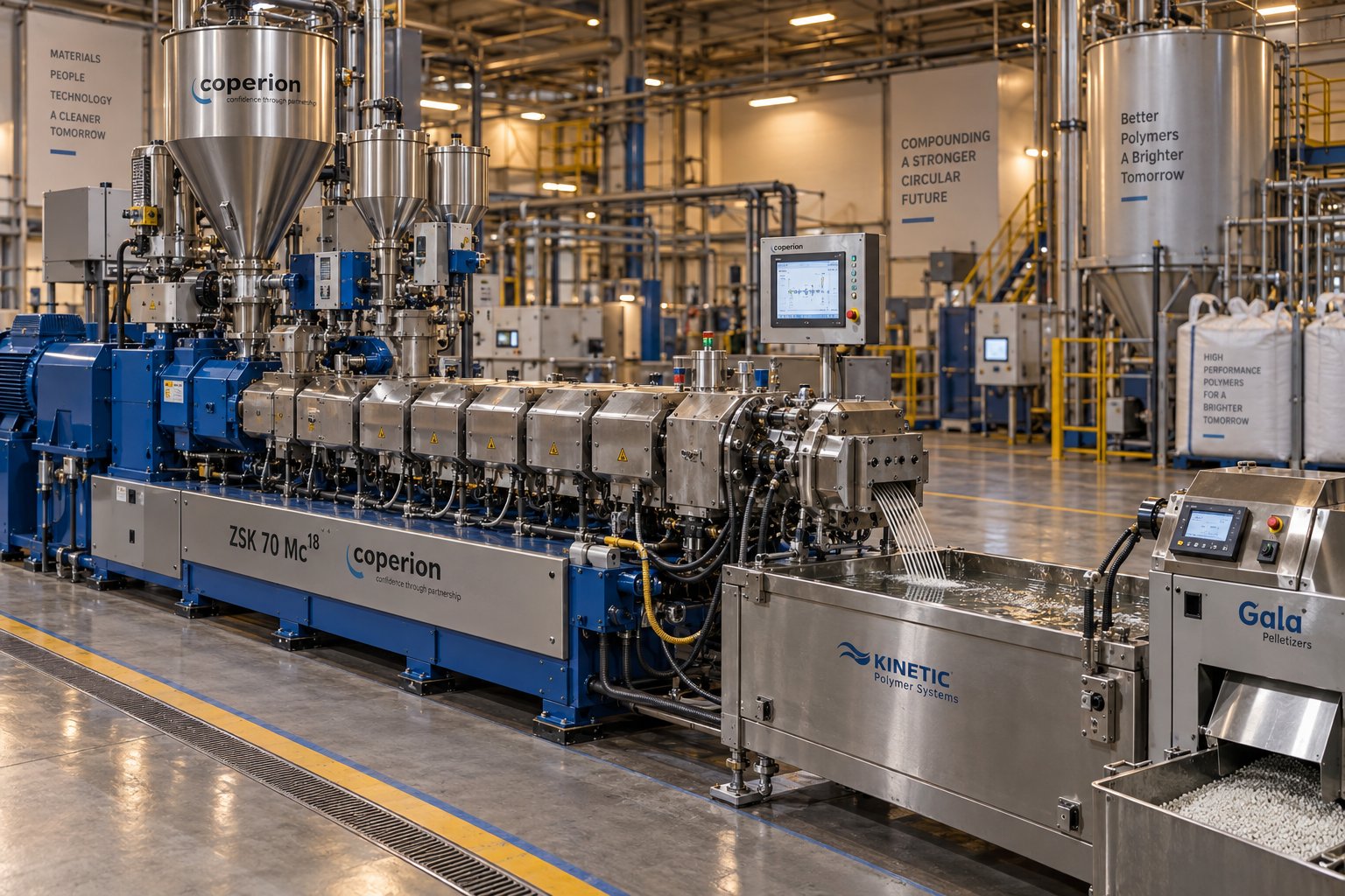
Parallel Twin Screw Extruder for Compounding Demystified: Lab to Line
Oct 21, 2026
Learn how a parallel twin screw extruder for compounding works—from screw element design and zone configuration to lab-to-production scale-up and process optimization.
Read Article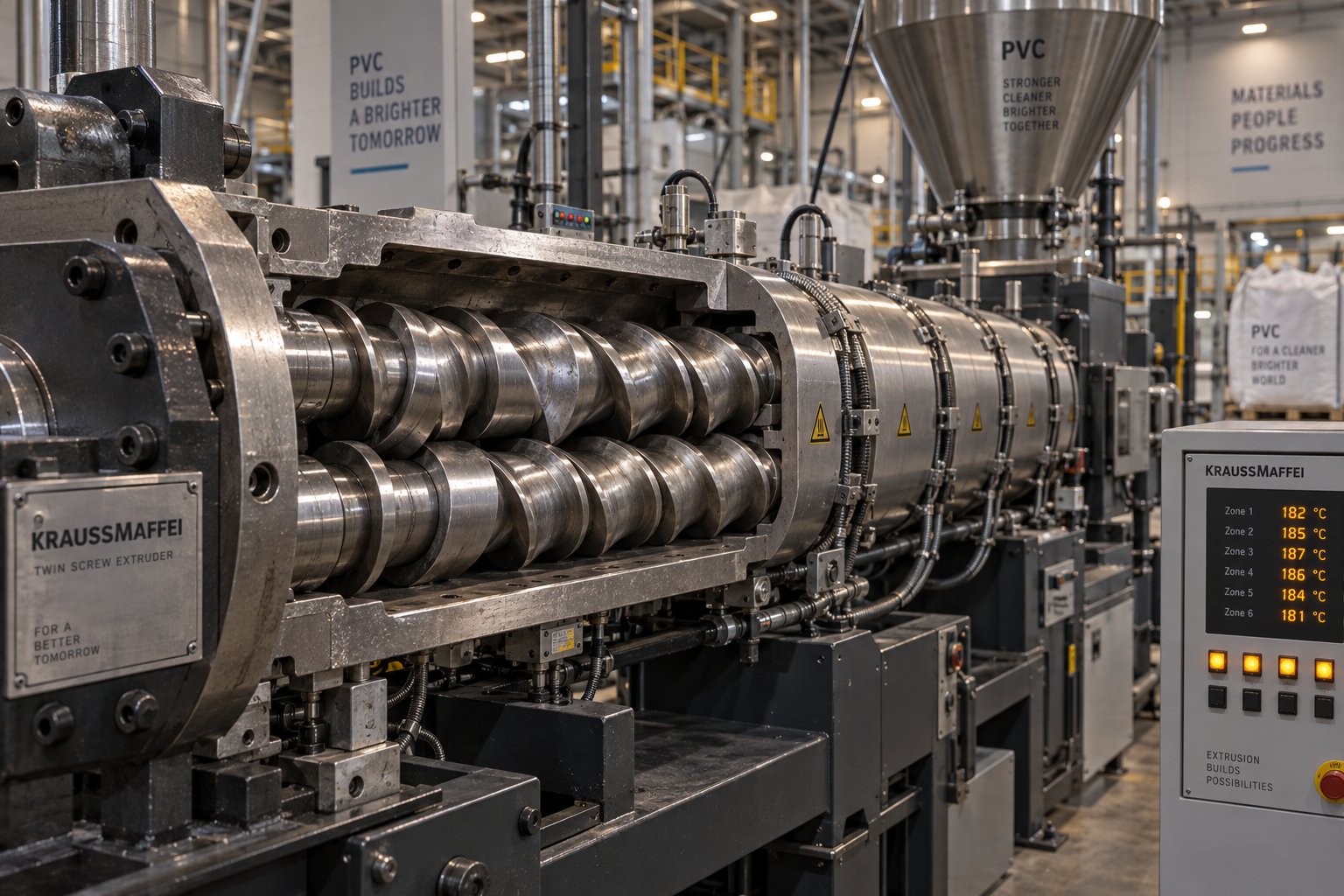
Twin Screw Extruder for PVC: The Setup Mistake Draining Profit
Oct 21, 2026
Learn how to match twin screw extruder configurations to PVC applications. Covers conical vs parallel, counter-rotating vs co-rotating, wear management, and troubleshooting.
Read Article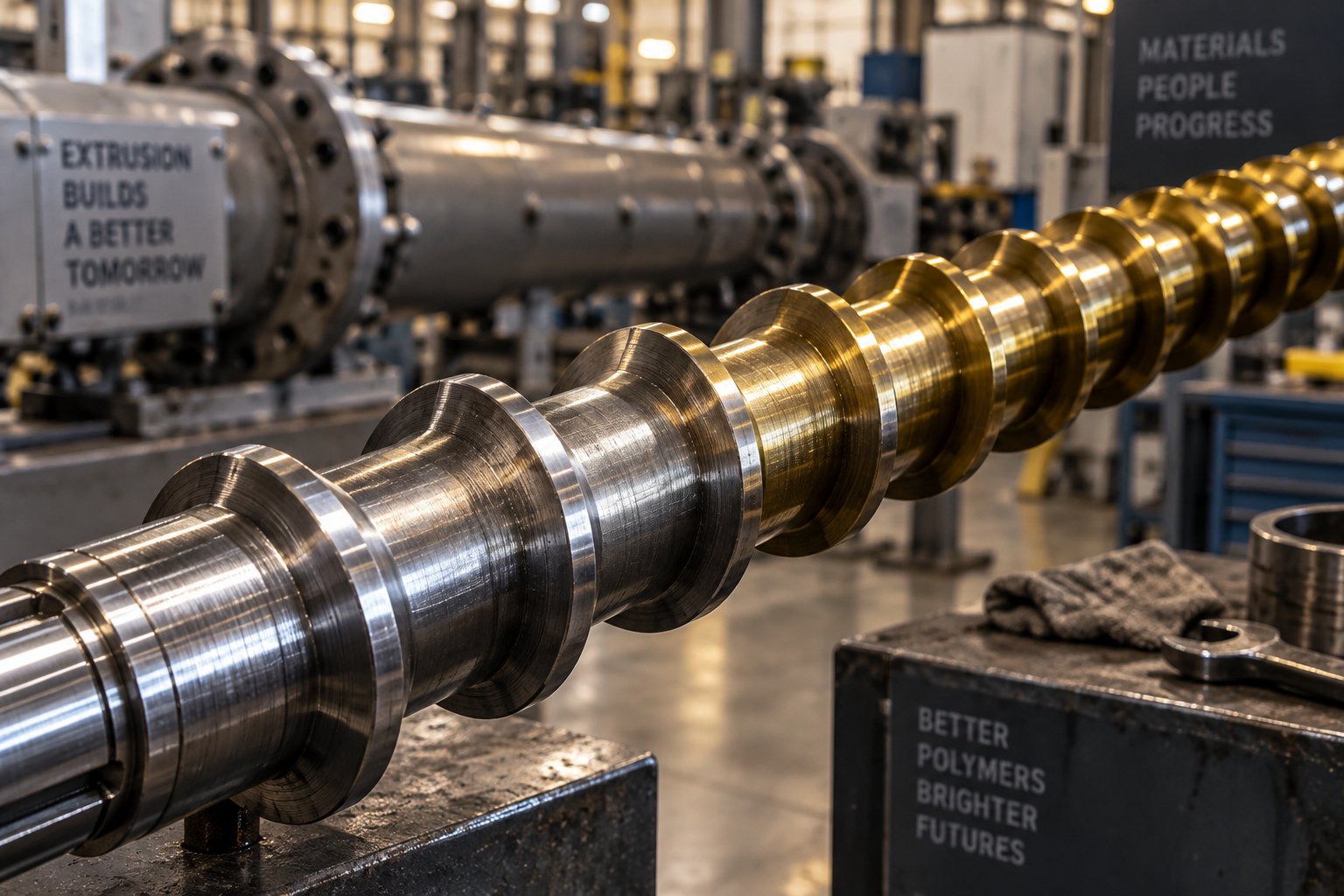
Plastic Extruder Screw Material Decoded: From Metallurgy to ROI
Oct 20, 2026
Learn how to select the right plastic extruder screw material — from carbon steel to bimetallic PM tool steels — matched to your resin, filler, and cost targets.
Read ArticleLooking for something else?
Search by material, symptom or product and jump straight to the relevant page.
These are navigation suggestions based on keyword matching — not a quotation, not a delivery commitment, and not a substitute for engineering review. Final specification is confirmed by our engineers against your drawings and processed material.
Need help with screw barrel selection?
Share your machine model, processed material and application. Our team can help with pricing and technical support.