

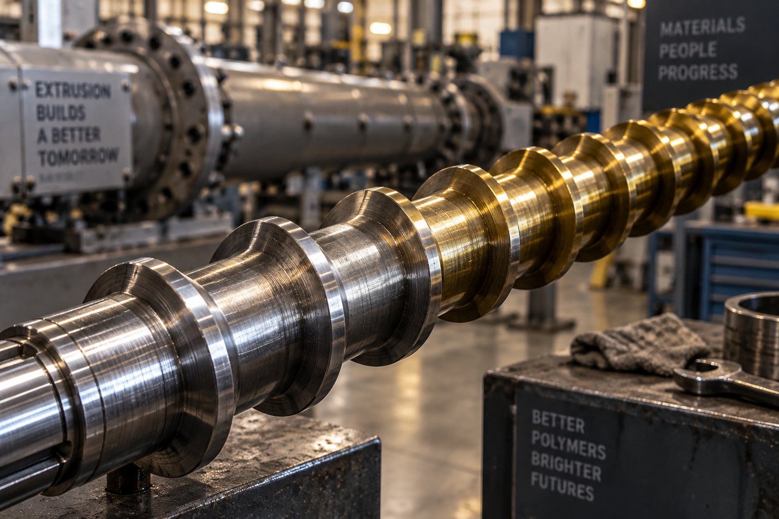
Why Screw Material Is the Most Critical Decision in Plastic Extrusion
Plastic extruder screw material refers to the specific steel grades, alloys, and composite metallurgies used to manufacture the helical flight screw that conveys, melts, and pressurizes polymer inside an extruder barrel. It encompasses three interconnected layers: base steel chemistry, hardening treatments such as nitriding or through-hardening, and surface coatings or bimetallic linings applied to extend service life. Every pellet of resin your line processes touches this screw. Every abrasive filler particle grinds against it. Every corrosive off-gas attacks it. The metallurgy you choose determines uptime, melt quality, energy consumption, and how often you shut down for a costly replacement.
What Plastic Extruder Screw Material Actually Means
Think of an extruder screw as more than a single hunk of steel. It is a system of material properties engineered to survive extreme conditions simultaneously—abrasion from glass fibers, corrosion from acidic decomposition gases, cyclic mechanical stress from torque loads, and sustained heat that can exceed 350 °C in high-performance polymer applications. The term "plastic extruder screw material" captures all of these design variables in one phrase. A screw extruder built for unfilled polyethylene film has entirely different metallurgical needs than one compounding glass-filled nylon at high throughput.
The same screw geometry made from two different materials can yield drastically different service lives depending on the polymer processed. Material selection is not a secondary spec—it is a primary engineering decision.
Why Material Selection Deserves More Attention Than It Gets
Many processors default to whichever steel their OEM supplies without evaluating whether it matches their actual resin, filler load, or throughput target. The consequences of that mismatch are real and expensive. Premature flight wear increases screw-to-barrel clearance, which reduces conveying efficiency and causes melt inconsistencies. Iron contamination from a worn screw can discolor light-colored products, driving up scrap rates. Unplanned downtime for an emergency screw change disrupts production schedules and delivery commitments.
Using inappropriate materials can lead to accelerated wear, frequent replacements, and compromised product quality—problems that compound over thousands of operating hours. Upgrading from a standard nitrided steel to a bimetallic screw can extend service life by up to five times in abrasive or corrosive environments, dramatically reducing replacement costs and downtime.
This article goes beyond simple material lists. It connects metallurgy, heat treatment science, resin chemistry, failure analysis, and total cost of ownership into a single decision framework—giving you the tools to match your plastic extruder screw to the exact demands of your process rather than settling for a generic default.
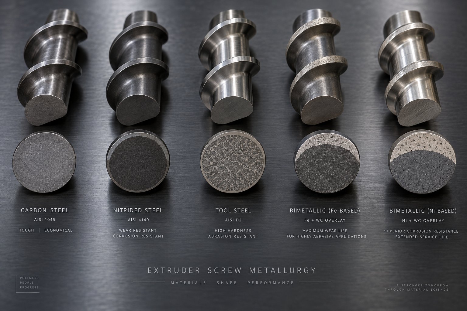
The Complete Spectrum of Extruder Screw Materials From Carbon Steel to Bimetallic
Choosing a plastic extruder screw material is not a single decision—it is a walk across a wide spectrum of steel grades, alloy systems, and composite constructions, each engineered for a different balance of hardness, toughness, corrosion resistance, and cost. The problem? Most resources only cover a narrow slice of that spectrum. You'll find articles that mention nitriding steels but ignore powder metallurgy options, or pages that discuss bimetallic barrels while skipping stainless steel grades entirely. What follows is the full picture, organized from budget-friendly carbon steels to premium bimetallic assemblies, so you can see exactly where each option fits—and where it falls short.
Carbon Steels and Low-Alloy Steels
At the entry level, carbon and low-alloy steels form the backbone of general-purpose extruder screws. AISI 1045 (equivalent to 45# steel in Chinese designation, or C45 under DIN/EN standards) is a medium-carbon steel commonly used for screws processing non-abrasive, non-corrosive commodity resins like LDPE and general-purpose PP at moderate throughputs. It machines easily and costs relatively little, but it offers limited wear resistance without surface treatment.
Step up to AISI 4140 (equivalent to 40Cr or 42CrMo4 in DIN), and you get a chromium-molybdenum alloy steel that delivers noticeably better strength and fatigue resistance. Pre-hardened to 28–32 HRC, 4140 is the dominant base material for general-purpose screw extruders worldwide, accounting for roughly 80% of all installed screws globally. Its close relative, AISI 4340 (approximately 10% stronger due to added nickel content), is preferred for high-torque applications processing viscous resins like fractional-melt HDPE. Without surface hardening, though, both grades are suitable only for unfilled commodity polymers where abrasive and corrosive wear are minimal.
Nitriding Steels and Alloy Tool Steels
When you need more surface hardness without sacrificing core toughness, nitriding steels enter the picture. The most widely specified grade is 38CrMoAlA—a chromium-molybdenum-aluminum alloy steel purpose-built for the nitriding process. Why the aluminum? It enables deep nitrogen diffusion during gas nitriding, forming a hard nitride-rich case that can reach 950–1,100 HV (approximately 68–72 HRC equivalent) at the surface while the core remains tough enough to handle torsional loads. This combination makes 38CrMoAlA the workhorse screw material across much of Asia and a common specification for mid-duty extruder screws globally.
For more demanding abrasive or thermal conditions, alloy tool steels raise the performance ceiling significantly. Consider three grades that appear frequently in screw plastic extruder specifications:
- AISI D2 (DIN 1.2379) — A high-carbon, high-chromium cold-work tool steel. Through-hardened to 58–62 HRC, D2 delivers four to six times the abrasion resistance of 4140 at equivalent flight geometry. In 30% glass-filled nylon, for example, D2 screws typically last 12,000–15,000 hours compared to 3,000 hours for nitrided 4140. The trade-off is moderate corrosion resistance and lower impact toughness.
- AISI H13 (DIN 1.2344) — A hot-work tool steel heat-treated to 44–52 HRC. H13 retains useful hardness up to approximately 550 °C, making it the go-to choice for injection screws with repeated thermal cycling and for processing high-temperature engineering polymers like PEEK and PPS.
- AISI A2 — An air-hardening tool steel that offers a middle ground between D2's extreme hardness and H13's toughness, with good dimensional stability during heat treatment. It suits applications needing moderate abrasion resistance without the brittleness risk of D2.
Powder Metallurgy and Bimetallic Solutions
Imagine taking the hardest carbide particles found in conventional tool steels and distributing them perfectly uniformly throughout the entire steel matrix—no segregation, no weak spots, no large carbide clusters waiting to chip out. That is precisely what powder metallurgy (PM) tool steels achieve. Grades like CPM 9V, CPM 10V, and CPM 15V from the Crucible Particle Metallurgy process use atomized powder consolidated under high pressure to produce carbide distributions impossible in conventionally cast steels.
CPM 10V (2.45% C, 5.25% Cr, 9.75% V) is especially notable. Its uniformly distributed vanadium carbides—each particle reaching approximately 2,500 HV in individual hardness—make it a top-tier choice for severely abrasive compounds. Standardized pin-on-disk abrasion testing per ASTM G99 shows CPM 10V outperforming D2 by three to five times in silicon carbide abrasive contact. In production environments processing 40–60% mineral-filled HDPE, CPM 10V extruder screws routinely exceed 20,000 hours of service life. The raw material cost premium is substantial—roughly 2.5 to 4 times that of D2—but the math favors PM grades convincingly in high-wear applications when total cost of ownership is calculated over a realistic production horizon.
Bimetallic construction takes a different approach entirely. Rather than making the entire screw from a single expensive alloy, it pairs a tough, ductile core (typically 4140 or 4340 at 28–35 HRC) with a wear-resistant alloy deposited on the working surfaces—flight tips, flanks, and outer diameter. The overlay alloy can be nickel-boron, cobalt-chromium (Stellite), tungsten carbide in a metal matrix, or high-chromium white iron, applied via plasma transferred arc (PTA) welding, HVOF thermal spray, or laser cladding. A bimetallic screw and barrel pair typically lasts two to three times longer than nitrided equivalents in abrasive or corrosive service, and the modular nature of the overlay means screws can be rebuilt by reapplying a fresh wear layer when the first one erodes.
One category that rarely gets discussed in screw material guides is stainless steel. Yet for food-grade extrusion, medical device manufacturing, or processing corrosive resins like PVC, stainless grades fill a critical gap. 17-4 PH stainless steel offers a yield strength near 175 kPSI—almost double that of 4140—along with 16% chromium content for excellent corrosion resistance. Recognized screw design authority Tim Womer recommends 17-4 PH as the preferred base material for any screw under 35 mm diameter, where it eliminates breakage risk while resisting the hydrochloric acid attack that degrades chrome-plated 4140 in PVC service. For applications requiring full FDA or pharmaceutical compliance, 316L austenitic stainless provides superior resistance to a broad range of chemical environments, though its lower hardness limits it to non-abrasive duty.
| Material Family | Typical Hardness (HRC) | Primary Advantage | Primary Limitation | Common Polymer Applications |
|---|---|---|---|---|
| AISI 1045 Carbon Steel | 20–28 (unhardened) | Low cost, easy machinability | Minimal wear and corrosion resistance | Unfilled LDPE, PP at low throughput |
| AISI 4140 / 4340 (Nitrided) | 55–62 (surface) | Good toughness, weldable for hardfacing | Shallow nitrided case; limited corrosion resistance | Unfilled commodity polyolefins, styrenics |
| 38CrMoAlA (Nitrided) | 65–72 HRC equiv. (surface) | Deep nitrided case, excellent core toughness | Limited abrasion resistance against hard fillers | Lightly filled compounds, general extrusion |
| AISI D2 Tool Steel | 58–62 | High through-hardness, 4–6x abrasion resistance vs. 4140 | Moderate corrosion resistance, lower impact toughness | Glass-filled nylons, mineral-filled compounds |
| AISI H13 Tool Steel | 44–52 | Retains hardness to ~550 °C, thermal fatigue resistance | Lower room-temperature hardness than D2 | PEEK, PPS, PEI, high-temp injection cycles |
| CPM 9V / 10V / 15V (PM Tool Steel) | 60–64 | Extreme abrasion resistance, uniform carbide distribution | High material cost (2.5–4x D2), limited corrosion resistance | 30–60% glass/mineral-filled HDPE, PA, severe abrasive duty |
| Bimetallic (Stellite / WC overlay on 4140/4340) | 36–52 (Stellite) or 70+ HRC equiv. (WC) | Combines tough core with premium wear surface; rebuildable | Higher initial cost; overlay thickness limits on high-L/D screws | Abrasive-corrosive compounds, PVC, filled engineering resins |
| 17-4 PH Stainless Steel | 28–44 (depending on condition) | High strength, excellent corrosion resistance (16% Cr) | Higher material cost (~2x 4140), limited abrasion resistance | PVC, food-grade, medical, small-diameter screws (<35 mm) |
| 316L Stainless Steel | ~25 (annealed) | Broad chemical resistance, FDA-compliant | Low hardness, unsuitable for abrasive polymers | Pharmaceutical, food-contact, non-abrasive specialty resins |
This spectrum—from a $2,000 nitrided 4140 screw to a $34,000 bimetallic CPM 10V assembly—represents far more than a price range. Each step up the material ladder buys a specific performance characteristic: deeper surface hardness, better carbide structure, higher hot-hardness retention, or superior chemical resistance. The key is matching the material tier to the actual wear mechanism your process imposes, rather than defaulting to whatever sits in the middle.
Of course, knowing the catalog of available materials is only half the equation. Understanding why certain alloys outperform others—at the level of carbide formation, grain structure, and tempering behavior—is what separates an informed selection from an educated guess.
The Metallurgy Behind Extrusion Screw Performance and Wear Resistance
Material grades and hardness numbers tell you what a screw is made of. They don't tell you why one steel outlasts another by a factor of five in the same extruder running the same resin. That answer lives deeper—inside the steel's microstructure, where tiny carbide particles, grain boundaries, and tempering reactions determine how an extrusion screw resists the relentless grinding, chemical attack, and thermal stress of real-world production.
Carbide Formation and Grain Structure
Every tool steel used in screw manufacturing contains hard carbide particles embedded within a softer steel matrix. Think of it like concrete: the matrix is the cement that holds everything together, and the carbides are the aggregate stones that resist grinding forces. The type, size, quantity, and distribution of those carbide "stones" directly control how well a screw fights abrasive wear from glass fibers, mineral fillers, or wood flour.
Different alloying elements form different types of carbides, each with distinct hardness levels:
- Chromium carbides (M7C3, M23C6) — Found in D2 and high-chromium steels. These reach approximately 1,600–1,800 HV and provide solid abrasion resistance against moderate fillers.
- Vanadium carbides (MC type) — The hardest commonly encountered carbide in tool steels, exceeding 2,800 HV. Grades like CPM 10V rely on a high volume fraction of vanadium carbides for extreme wear resistance.
- Tungsten and molybdenum carbides (M2C, M6C) — These contribute to hot-hardness retention and tempering resistance, which is why they appear in H13 and high-speed steels used for injection screw applications and high-temperature polymer processing.
Here's the critical insight: it's not just the carbide type that matters—it's how those carbides are distributed. In conventionally cast tool steels, slow cooling during solidification allows carbides to grow large and cluster together in bands. D2 steel, for example, typically contains primary chromium carbides larger than 10 microns, and those oversized particles create weak points where chipping or spalling can initiate under mechanical stress. When a flight tip chips, you lose not just the carbide particle but also a chunk of the surrounding matrix, accelerating wear in an uneven pattern.
Powder metallurgy steels solve this problem at the source. By atomizing molten steel into fine powder—each particle acting as its own tiny ingot cooling almost instantly—PM processing produces carbides in the 1–5 micron range with uniform distribution throughout the matrix. No banding. No clusters. The practical result for an extrusion screw is a flight surface that wears evenly and predictably rather than losing material in random chunks. Even with an aggressive extrusion screw compression ratio that creates intense shear forces in the transition zone, PM tool steels maintain consistent flight geometry far longer than their conventionally cast counterparts.
Volume fraction matters, too. Each percentage point increase in vanadium carbide content reduces wear rate by approximately 3–5% under standardized abrasion testing. High-vanadium PM grades can achieve carbide volume fractions of 15–25%, which is why CPM 10V and CPM 15V dominate the most abrasive compounding applications—those numbers simply aren't achievable through conventional steelmaking without catastrophic brittleness.
How Tempering Behavior Affects Screw Longevity
Imagine you measure a brand-new screw at 52 HRC on the shop floor. It looks perfect on paper. But six months later, the flight tips are soft enough to gouge with a file, even though your barrel temperatures haven't changed. What happened? The steel's tempering curve didn't account for the actual service temperatures inside your extruder.
Tempering is a controlled reheating step performed after hardening to relieve internal stresses and improve toughness. Every tool steel has a characteristic tempering response—a curve showing how hardness changes with tempering temperature. Most carbon and low-alloy steels lose hardness steadily as tempering temperature rises. But certain alloy tool steels and high-speed steels exhibit a phenomenon called secondary hardening: a hardness peak that appears when tempering is performed in the 500–600 °C range. This peak results from the precipitation of fine, stable alloy carbides—particularly vanadium carbides (VC) and molybdenum carbides (M2C)—from the supersaturated martensitic matrix.
Research on AISI H13 tool steel demonstrates this effect clearly. Specimens tempered at 200 °C showed declining hardness because secondary hardening doesn't activate at low temperatures. At 500 °C and 550 °C, however, hardness recovered to near as-built levels—around 46–47 HRC—due to the fine dispersion of chromium carbides (M7C3) within the matrix. The catch? Over-tempering at 500 °C for 5 hours or 550 °C for 3 hours caused those same carbides to coarsen and cluster, dropping hardness below 42 HRC and degrading tensile strength. The difference between optimal secondary hardening and destructive over-tempering can be surprisingly narrow.
This matters enormously for plastic extruder screws because barrel zone temperatures routinely sit in exactly the range where tempering effects are most active. An injection screw cycling through zones set at 280–350 °C may seem safe, but remember that localized frictional heating at flight tips—especially under high-viscosity resins or aggressive screw speeds—can push metal surface temperatures well above the nominal barrel setpoint. If the screw's steel wasn't tempered at or above those real service temperatures, it will continue to temper in service, slowly softening over hundreds of operating hours.
A screw that tests at adequate hardness on the bench may soften in service if the steel's tempering curve does not account for actual barrel zone temperatures. Always verify that the final tempering temperature exceeded the maximum expected service temperature by a safe margin.
Hot-work steels like H13, along with high-speed steels containing tungsten and molybdenum, are specifically engineered to maintain hardness through secondary hardening at elevated temperatures. Vanadium-containing hot-work grades retain over 90% of initial hardness after 1,000 hours at 550 °C, while conventional H13 without vanadium optimization can lose 15–20% of its hardness under identical exposure. For processors running PEEK, PEI, or PPS above 350 °C, selecting a screw steel with a verified secondary hardening peak above the actual processing temperature is not optional—it's essential for predictable service life.
Understanding these metallurgical mechanisms—carbide type, distribution, volume fraction, and tempering response—transforms screw material selection from a catalog exercise into a genuine engineering decision. Yet even the best base metallurgy reaches its practical limit without the right heat treatment and surface hardening. The processes applied after the steel is forged often matter just as much as the alloy composition itself.
Heat Treatment and Surface Hardening That Transform Screw Performance
A screw forged from premium tool steel still starts as a relatively soft workpiece. It is heat treatment—the precise sequence of heating, cooling, and reheating—that unlocks the steel's full potential. For extruder screws and barrels alike, the difference between a treatment that was correctly specified and one chosen by default can mean double the service hours or half the replacement cost. Yet most material guides list treatment names like "nitrided" or "through-hardened" as if they were self-explanatory. They're not. Each process alters the steel in a fundamentally different way, and each suits a different combination of base material and wear challenge.
Through-Hardening and Case Hardening Explained
Through-hardening is exactly what it sounds like: the entire cross-section of the screw is heated above its austenitizing temperature, quenched rapidly (in oil, water, or air depending on the grade), and then tempered back to a target hardness. The result is uniform hardness from the flight tip down to the root diameter. This is the standard treatment for alloy tool steels like D2, H13, and A2, where the steel's high alloy content allows full transformation throughout the part. It works well when you need the entire screw body to resist wear—for example, injection molding screws processing abrasive glass-filled compounds where the root surface erodes along with the flights.
Case hardening takes the opposite philosophy. Instead of hardening the full cross-section, you create a hard outer shell on a tough, ductile core. The two most common methods are:
- Carburizing — The screw is heated in a carbon-rich atmosphere (typically at 900–950 °C) for hours or days, allowing carbon atoms to diffuse into the surface. The carbon-enriched layer is then quenched to form high-hardness martensite, while the low-carbon core remains tough and shock-absorbing. Carburizing suits lower-alloy steels like 4140 and 4340 that cannot achieve high through-hardness on their own.
- Carbonitriding — A variation that introduces both carbon and nitrogen simultaneously at slightly lower temperatures (820–900 °C). The added nitrogen improves surface hardness and creates a more stable compound layer, producing a case that resists both abrasion and mild corrosion better than carburizing alone.
The trade-off is straightforward: through-hardened screws resist wear uniformly but sacrifice some impact resistance, while case-hardened screws absorb shock loads in the core but depend on the integrity of a relatively thin hardened layer—typically 0.5 to 2.0 mm deep. If that case wears through in a high-abrasion zone, the soft core beneath erodes rapidly.
Nitriding and Its Variants for Screw Surfaces
Nitriding occupies a unique position among surface treatments because it operates below the steel's tempering temperature—typically between 500 °C and 575 °C—so it does not distort the screw or reduce the core hardness established during prior heat treatment. That single characteristic makes nitriding the most widely applied surface treatment for injection molding screws and barrels across virtually every polymer processing segment.
The process introduces nitrogen atoms into the steel surface, where they react with alloying elements—particularly chromium, aluminum, and molybdenum—to form extremely hard nitride compounds. The resulting hardened zone consists of two distinct layers:
- Compound zone (white layer) — A thin (typically 5–25 microns), very hard surface layer composed primarily of iron nitrides (Fe2-3N and Fe4N). This layer provides initial wear and corrosion resistance but can be brittle if excessively thick.
- Diffusion zone — A deeper region (typically 0.2–0.7 mm in screw applications) where nitrogen atoms sit within the steel matrix and form fine alloy nitride precipitates. This zone provides the bulk of the load-bearing hardness improvement.
Three nitriding variants are commonly specified for extruder screws:
Gas nitriding uses ammonia (NH3) as the nitrogen source. The screw is placed in a sealed furnace, and ammonia dissociates at the steel surface, releasing atomic nitrogen that diffuses inward. Gas nitriding is well-suited for shorter screws and produces consistent, repeatable case depths. Processing times typically range from 20 to 90 hours depending on desired depth and steel composition.
Ion (plasma) nitriding replaces the ammonia atmosphere with a low-pressure nitrogen-hydrogen gas mixture. A high-voltage electrical field ionizes the gas, creating a plasma glow discharge that bombards the screw surface with energetic nitrogen ions. Advanced Heat Treat Corp. reports that processing temperatures for plasma nitriding of extruder screws typically range from 500 °C to 575 °C, with the final temperature selected based on the treated material and required case depth. A major practical advantage is selective treatment: surfaces that don't need hardening can be mechanically masked so nitrogen reaches only the flight lands, tips, and root—leaving threads and shank ends unaffected.
The achievable hardness depends heavily on the substrate steel. Hardness profile data from ion nitrided screws shows that AISI 4140 reaches moderate surface hardness, while specialty nitriding steels like Nit135M and H13 exceed 70 HRC equivalent—making screws from those substrates suitable for demanding abrasion applications. Plasma nitriding also handles extremely long screws; vertical vacuum chambers can process parts exceeding 12 meters (40 feet) in length.
Ferritic nitrocarburizing (FNC) adds a small amount of carbon to the nitriding atmosphere, enhancing the compound zone's thickness and corrosion resistance. FNC treatments are often specified when screws face both mild abrasion and corrosive off-gases—common in PVC extrusion or processing flame-retardant compounds—because the enriched compound layer acts as a chemical barrier alongside its wear-resistant function.
Advanced Surface Treatments and Coatings
When nitriding alone can't keep up with the severity of wear, several advanced treatments extend screw life further—each targeting a specific failure mode.
Induction hardening uses a high-frequency alternating magnetic field to rapidly heat only the outermost layer of the screw—typically the flight tips—followed by immediate quenching. Because the heating is localized and takes just seconds, the rest of the screw remains unaffected. This makes induction hardening ideal for selectively reinforcing flight tips in the feed zone, where solid pellet friction is most aggressive, without risking distortion of the entire part.
Laser cladding with stellite (cobalt-chromium) or tungsten carbide overlays deposits a metallurgically bonded wear layer directly onto screw flights. The laser's focused heat input melts a thin substrate layer along with the feed powder, creating a fusion bond far stronger than thermal spray coatings. Tungsten carbide clad layers can exceed 70 HRC equivalent and resist even the most aggressive glass-fiber or mineral-filled compounds. Laser cladding also permits rebuilding worn screws to original dimensions—a significant cost advantage over full replacement.
PVD and CVD thin-film coatings represent the emerging frontier for screw surface engineering. Titanium nitride (TiN), chromium nitride (CrN), and diamond-like carbon (DLC) coatings deposit extremely hard, low-friction layers just 1–5 microns thick onto finished screws. Research comparing TiN, CrN, and WC/C coatings on steel substrates found that CrN exhibited the highest wear resistance under dry sliding conditions, outperforming TiN by a factor of two in standardized reciprocating wear tests. CrN also offers superior corrosion resistance at elevated temperatures—a valuable attribute for screws processing corrosive resins. DLC coatings, with friction coefficients as low as 0.05, reduce polymer adhesion and improve melt release, particularly useful for sticky resins like TPU or EVA. The practical limitation of thin-film coatings is their minimal thickness: once the layer wears through, the underlying substrate is exposed, so they work best as supplements to a properly hardened base rather than standalone solutions.
| Treatment Type | Typical Case Depth | Achievable Surface Hardness | Dimensional Distortion Risk | Best-Fit Screw Material Substrates |
|---|---|---|---|---|
| Through-Hardening (Quench & Temper) | Full cross-section | 44–64 HRC (grade dependent) | Moderate (requires post-grind) | D2, H13, A2, high-speed steels |
| Carburizing | 0.5–2.0 mm | 58–63 HRC | Moderate to high | 4140, 4340, 8620 low-alloy steels |
| Gas Nitriding | 0.2–0.7 mm | 950–1,100 HV (65–72 HRC equiv.) | Very low (no quench) | 38CrMoAlA, Nit135M, 4140, 4340 |
| Ion (Plasma) Nitriding | 0.1–0.5 mm | Up to 70+ HRC equiv. on H13/Nit135M | Very low (selective masking possible) | 4140, 4340, H13, Nit135M, CPM 9V |
| Ferritic Nitrocarburizing (FNC) | 0.1–0.3 mm (compound zone thicker) | 900–1,050 HV (64–70 HRC equiv.) | Very low | 4140, 4340, 38CrMoAlA |
| Induction Hardening | 1–5 mm (localized) | 50–62 HRC | Low (localized heating only) | 4140, 4340, 1045 carbon steels |
| Laser Cladding (Stellite / WC) | 0.5–3.0 mm overlay | 45–55 HRC (Stellite) or 70+ HRC equiv. (WC) | Low (controlled heat input) | 4140, 4340, any machinable base steel |
| PVD/CVD Coatings (TiN, CrN, DLC) | 1–5 microns | 2,000–3,500 HV | None (low-temp deposition) | Any pre-hardened steel; best on H13, D2, PM steels |
Each treatment on this list solves a different problem. Nitriding protects general-purpose screws without distortion. Through-hardening gives tool steels their full abrasion resistance. Laser cladding rebuilds and upgrades worn screws. PVD coatings slash friction for sticky polymers. The real power comes from combining treatments—for instance, plasma nitriding an H13 screw and then applying a CrN thin-film topcoat creates a multilayer defense against both abrasion and corrosion that no single process can match.
Choosing the right treatment, however, depends entirely on the resin and filler you're processing. A treatment that excels against glass-fiber abrasion may be useless against the hydrochloric acid released by PVC. The decisive variable isn't the screw or its coating—it's the polymer chemistry on the other side of the metal surface.
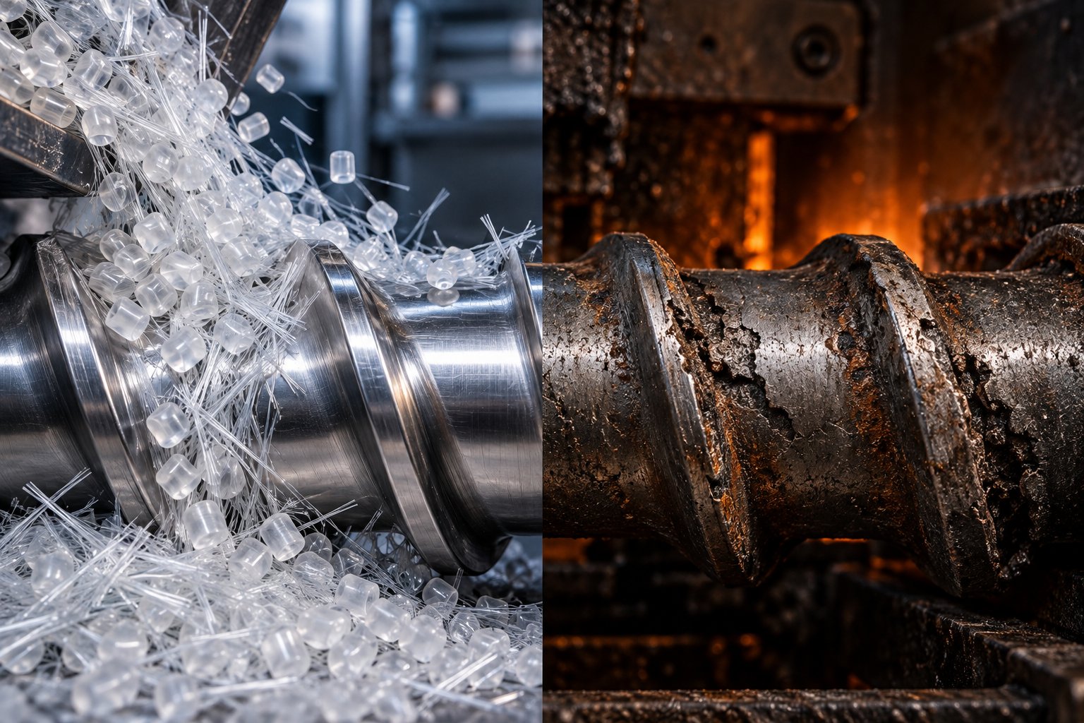
Matching Screw Materials to Specific Resins, Fillers, and Processing Challenges
Metallurgy specs on a data sheet look impressive, but they don't answer the question that actually matters on your production floor: which screw material should I pair with the specific resin and filler running through my extruder barrel? A CPM 10V screw is overkill for unfilled LDPE film. A nitrided 4140 is dangerously underprepared for 40% glass-filled nylon. The mismatch between screw metallurgy and polymer chemistry is where most premature failures originate—and where the biggest ROI gains hide.
Rather than listing materials and hoping you can work backward to your application, this section flips the framework. It starts with the processing challenge your resin creates and works forward to the material solution that neutralizes it.
Abrasive Polymers and Filled Compounds
Glass fiber is the most common abrasive filler in plastics processing—and the most destructive to screw flight surfaces. Each glass fiber strand has a Mohs hardness of roughly 6.5, which is harder than the steel matrix in most tool steels and significantly harder than a nitrided surface once you account for the concentrated point-contact loading at fiber tips. Mineral fillers like calcium carbonate, talc, and wollastonite are somewhat softer but compensate with sheer volume: compounds loaded at 40–60% filler by weight expose the screw to an almost continuous abrasive slurry.
Wood flour and natural fiber composites present a different abrasion profile. The fibers themselves are relatively soft, but residual silica content in wood particles—combined with high filler loadings—produces measurable flight erosion over thousands of hours, particularly in the feed zone where solid material compresses against flight flanks.
Research on glass-fiber-reinforced polypropylene processed on twin-screw extruders confirms that fiber content directly accelerates wear severity. In that study, increasing glass fiber loading from 20 wt.% to 40 wt.% shortened resulting fiber lengths dramatically—meaning more fiber breakage events, more exposed fiber ends, and more abrasive contact per revolution. Kneading block elements, which create the intense shear needed for dispersion, experienced the most aggressive fiber-to-metal interaction. The implication for screw material selection is clear: mixing and kneading zones in a compounding extruder barrel need harder metallurgy than simple conveying zones.
Screw geometry amplifies or mitigates the abrasive load. A barrier screw with a tight melt-channel clearance forces filler particles into concentrated contact with the barrier flight. A mixing screw processing glass-filled nylon subjects distributive mixing pins to constant abrasive bombardment. In contrast, a simple metering screw conveying unfilled LDPE film encounters virtually no abrasive challenge. Different geometries demand different metallurgical solutions, even when the base resin is identical.
Recommended material responses for abrasive duty, ranked by increasing severity:
- Lightly filled compounds (10–20% CaCO3 or talc) — Nitrided 38CrMoAlA or gas-nitrided 4140 provides adequate flight protection at moderate cost. Plan for more frequent dimensional inspections.
- Moderately filled compounds (20–35% glass or mineral) — D2 tool steel through-hardened to 58–62 HRC, or bimetallic screws with Stellite flight overlays, delivers meaningful life extension. Hardfaced flight tips on a 4340 base offer a cost-effective intermediate step.
- Heavily filled compounds (35–60% glass or mineral) — PM tool steels like CPM 10V or CPM 15V become the only practical option for screws expected to run beyond 15,000 hours. Bimetallic screws with a tungsten carbide matrix overlay on flight lands handle the most extreme loadings, especially in twin-screw compounding where intermeshing elements multiply abrasive contact intensity.
Corrosive Resins and Off-Gassing Polymers
Abrasion is visible—you can measure flight diameter loss with a micrometer. Corrosion is sneakier. It starts as microscopic pitting on the screw surface, often in the transition zone where rising melt temperatures first trigger resin decomposition, and then spreads beneath the surface before you ever notice a quality issue in your extrudate.
The worst offenders are well documented. PVC releases hydrochloric acid during thermal processing, which aggressively attacks nitrided steel surfaces and standard tool steels lacking sufficient chromium content. Acetal (POM) decomposes to produce formaldehyde and formic acid, eroding extrusion barrels and screws from the inside out. Fluoropolymers—PTFE, FEP, PFA—release hydrofluoric acid, one of the most corrosive substances encountered in any industrial setting. Even certain flame-retardant additives based on halogenated compounds generate corrosive byproducts that combine with moisture in the melt to form acidic solutions at the metal surface.
Why do standard nitrided steels fail in these environments? The iron nitride compound layer that provides excellent abrasion resistance is porous at the micro-scale. Acidic gases penetrate those pores, attack the underlying steel, and undermine the hardened case from beneath. The result is pitting that becomes a stress concentrator, which then accelerates fatigue cracking—a destructive synergy called tribocorrosion.
The metallurgical countermeasure is chromium. Chromium forms a passive oxide layer on the steel surface that resists acid attack far more effectively than iron nitrides. For PVC extrusion, chromium-rich stainless steels like 17-4 PH (with 16% Cr) or nickel-alloy bimetallic linings provide the corrosion barrier that standard nitrided screws simply cannot. Nickel-rich boron alloy liners with molybdenum and boride content, such as Colmonoy 56 or Colmonoy 83 coatings, offer dual corrosion and wear protection—a practical solution when extruder barrels and screws face both chemical attack and moderate abrasion simultaneously.
For fluoropolymer processing, where hydrofluoric acid attacks even many stainless grades, Hastelloy-based alloys or specialized nickel-chromium-molybdenum bimetallic linings become necessary. The cost is significant, but the alternative—replacing a corroded screw every few months—is far more expensive.
High-Temperature Engineering Polymers
PEEK, PEI (Ultem), PPS, and polyimide resins push processing temperatures to 350–420 °C. At those temperatures, the challenge shifts from surface chemistry to bulk metallurgy. You need a screw steel that retains its hardness after prolonged exposure to heat that would soften most conventional tool steels through ongoing temper degradation.
High-temperature polymer extrusion demands barrel temperatures between 380 °C and 450 °C, with tight thermal uniformity requirements because even small temperature fluctuations can degrade polymer chains. Screws operating in these environments experience sustained thermal loading that effectively re-tempers the steel continuously. A screw hardened to 58 HRC at room temperature may soften to 45 HRC after several hundred hours at 400 °C if the base steel lacks secondary hardening capability.
H13 hot-work tool steel is the standard recommendation here. Its chromium-molybdenum-vanadium chemistry produces stable carbide precipitates during secondary hardening that resist coarsening at elevated temperatures, maintaining useful hardness up to approximately 550 °C. For the most demanding applications—continuous PEEK extrusion at 400 °C or higher—high-speed steels like M2 or T15 with tungsten and cobalt additions retain hardness even further up the temperature scale.
Thermal expansion mismatch is a related but often overlooked hazard. When a screw and its paired extruder barrel have significantly different coefficients of thermal expansion, the operating clearance changes as the system heats up. Gap variations from CTE mismatches can cause seizing—direct metal-to-metal contact that damages flight tips and barrel walls in seconds. Matching the screw material's CTE to the barrel liner material is just as important as matching hardness to the resin's abrasive or corrosive character.
| Resin Family | Primary Processing Challenge | Recommended Screw Material Class | Recommended Surface Treatment | Key Selection Rationale |
|---|---|---|---|---|
| Commodity Polyolefins (LDPE, HDPE, PP — unfilled) | Minimal wear; cost sensitivity | 4140 / 4340 low-alloy steel | Gas nitriding or ion nitriding | Adequate hardness at lowest cost; long service life with non-abrasive melts |
| Styrenics (GPPS, HIPS, ABS — unfilled) | Mild adhesive wear; cosmetic sensitivity | Nitrided 4140 or 38CrMoAlA | Gas nitriding; optional CrN PVD topcoat | Smooth surface finish prevents melt hang-up; PVD reduces sticking in color-change applications |
| Engineering Nylons (PA6, PA66 — glass/mineral filled) | Severe abrasion from glass fiber and filler | D2, CPM 9V, CPM 10V; bimetallic WC overlay | Through-hardening; optional laser clad flight tips | High-volume hard carbides resist fiber erosion; PM steels provide uniform wear |
| PVC (rigid and flexible) | HCl corrosion from thermal decomposition | 17-4 PH stainless; Ni-alloy bimetallic | Colmonoy 56/83 coating or FNC | Chromium-rich passive layer resists acid; bimetallic liners protect barrel bore |
| Fluoropolymers (PTFE, FEP, PFA) | HF acid corrosion; high processing temperature | Hastelloy-based bimetallic; Ni-Cr-Mo alloys | Corrosion-resistant weld overlay | Standard steels and stainless grades corrode rapidly; specialized Ni alloys required |
| High-Temp Engineering (PEEK, PEI, PPS) | Sustained heat above 350 °C; hot-hardness loss | H13 hot-work tool steel; M2 high-speed steel | Through-hardening with secondary hardening temper; CTE-matched barrel pairing | Secondary hardening carbides maintain hardness at service temperature; CTE matching prevents seizing |
| Wood-Plastic Composites (WPC) | Moderate abrasion from silica; moisture-driven corrosion | D2 or bimetallic with Stellite overlay | FNC or plasma nitriding plus corrosion-resistant topcoat | Silica in wood flour erodes flights; moisture plus heat create mildly corrosive conditions |
Notice a pattern in this table? No single plastic extruder screw material dominates every row. Commodity polyolefins thrive on the most affordable nitrided steels, while corrosive PVC demands expensive stainless or bimetallic construction—and heavily filled engineering resins call for an entirely different metallurgical response. The right match depends on understanding which wear mechanism your specific resin and filler combination activates.
That raises a practical follow-up question: when a screw comes out of service prematurely, how do you determine which mechanism actually caused the failure? Choosing a better material for the replacement screw requires reading the evidence the worn screw leaves behind—wear patterns, pit locations, crack morphology—and tracing each clue back to its metallurgical root cause.
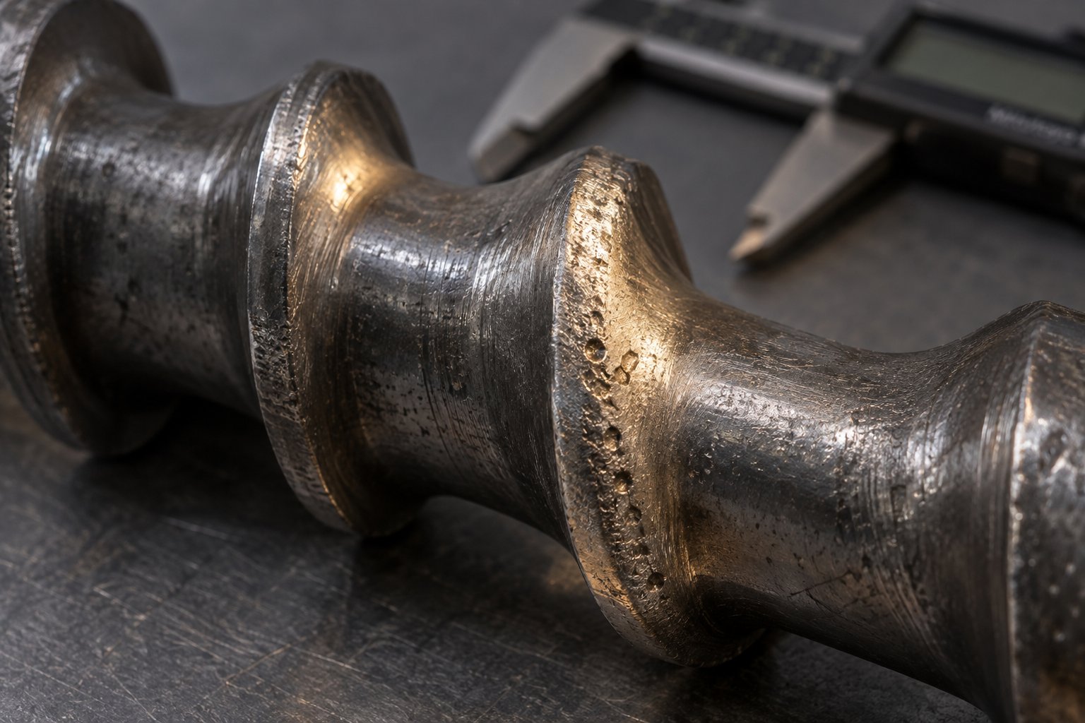
How Extruder Screws Fail and Which Materials Prevent Each Failure Mode
A worn screw tells a story. The location of the damage, the shape of the wear marks, and the surface texture of the eroded flights all point to a specific failure mechanism—one that demands a specific metallurgical response. Yet most processors treat every worn screw the same way: they order an identical replacement and hope it lasts longer. That approach ignores the root cause entirely. If the original material wasn't suited to the dominant wear mode, the replacement will fail on the same schedule.
Understanding how your screw barrel system degrades is the prerequisite for choosing materials that actually solve the problem. Three primary wear mechanisms attack extruder screws during service, and each one leaves a distinct forensic signature.
Adhesive Wear, Abrasive Wear, and Erosive Wear
Adhesive wear occurs when two metal surfaces—screw flight and barrel liner—come into direct contact under high pressure with insufficient lubrication. Imagine the first few minutes of a cold startup before the hopper fills completely with resin. The screw rotates against the barrel wall with little or no polymer melt acting as a lubricant film. Under these conditions, microscopic welding occurs at contact points between the flight tip and the barrel liner. As the screw continues rotating, those micro-welds tear apart, transferring material from one surface to the other. The result is galling—rough, torn patches on the flight OD that accelerate further contact and damage.
Extrusion expert Jim Frankland identifies unbalanced high-pressure areas as a primary driver of this mechanism. When screw design is too aggressive—meaning the compression rate forces solids downstream before enough melt has formed—the channel can plug momentarily with unmelted pellets. Instantaneous pressures at that plug can exceed 10,000 psi. Because the screw channel is eight to nine times the width of the flight, the localized pressure on the flight adjacent to the plug can reach four to four and a half times the channel pressure. With a much lower pressure on the opposite side of the screw, the enormous unbalanced force drives the flight into the barrel wall, tearing hardface material right off the flight surface. The telltale sign? A ragged lip of deformed hard surfacing extending off the trailing edge of the flight, usually concentrated over a span of three to six flights in the compression zone.
Material solutions for adhesive wear focus on reducing the friction coefficient and increasing galling resistance. Bimetallic screws with nickel-boron or cobalt-chromium (Stellite) flight overlays resist micro-welding far better than nitrided steels because their matrix chemistry is less prone to adhesive bonding with iron-based barrel liners. PVD coatings like CrN and DLC further reduce metal-to-metal friction during dry or starved-feed conditions.
Abrasive wear is the most common degradation mode in plastics processing, and the easiest to understand conceptually. Hard filler particles—glass fibers, mineral fillers, wood flour with residual silica—act like microscopic sandpaper trapped between the rotating screw flight and the barrel liner. Each particle scores the metal surface, removing material one tiny scratch at a time. As Xtrutech notes in their analysis of twin-screw wear, the sharp machined corners of screw and kneading elements gradually appear rounded, smooth, and occasionally polished as abrasion progresses.
The wear isn't uniform along the screw length. It typically concentrates at the last set of feed screws and first set of kneading elements—the zone where solid pellets and abrasive particles are first compressed and begin to melt. As abrasion advances, the melting point shifts further downstream, reducing the effective mixing length of the extruder and eventually limiting achievable output. Jim Frankland's flight-wear analysis confirms this pattern: filler particles cause micro-abrasions by being trapped between the rotating flight and barrel liner, and since the abrasive scratches are mostly invisible without magnification, the worn surface appears "almost polished" with rounded flight edges. This polished, rounded appearance—concentrated in the feed and compression sections where loose fillers haven't yet been incorporated into the melt—is the diagnostic fingerprint of abrasive wear.
Combating abrasion requires hard carbide particles in the screw steel that resist scoring. High-vanadium PM tool steels (CPM 10V, CPM 15V) and tungsten carbide bimetallic overlays place extremely hard particles—2,500+ HV for vanadium carbide, 2,400+ HV for tungsten carbide—directly in the path of abrasive fillers. The key is matching carbide hardness to filler hardness: glass fibers at Mohs 6.5 demand vanadium or tungsten carbides, while softer calcium carbonate fillers at Mohs 3 can be handled adequately by the chromium carbides in D2 tool steel.
Erosive wear appears where high-velocity melt streams impinge on screw surfaces at an angle. It is distinct from abrasion because the damage comes from fluid impact forces rather than trapped-particle grinding. Erosion is most severe around mixing elements, blister rings, and the leading edges of barrier flights—anywhere the melt path changes direction abruptly. The impinging stream carries filler particles at high velocity, and the impact removes material through a combination of micro-cutting and fatigue from repeated pressure pulses.
Erosive wear creates a characteristic scalloped or cratered surface, especially at melt channel entry points and downstream of restriction rings. Materials that resist erosion need a combination of hardness and toughness: a purely hard surface like a thin PVD coating may chip under repeated impact, while a purely tough material like ductile 4140 simply erodes too fast. Bimetallic screws with a thick (1–3 mm) Stellite or tungsten carbide clad layer provide the best compromise—hard enough to resist micro-cutting, thick enough to absorb impact energy without cracking.
Corrosive Pitting and Fatigue Cracking
Corrosion in an extruder screw barrel doesn't always announce itself with visible rust. It starts as microscopic pitting—tiny surface craters formed where acidic decomposition gases attack the steel. PVC releases hydrochloric acid. Fluoropolymers release hydrofluoric acid. Many flame-retardant additives produce brominated or chlorinated byproducts that react with trace moisture in the melt to form corrosive solutions. These chemical attacks concentrate in the transition zone, where rising melt temperatures first trigger resin decomposition, and along stagnant-flow areas where volatile gases linger against the metal surface.
Each pit, no matter how small, acts as a stress concentrator. Under the cyclic torsional and bending loads that every screw experiences during rotation, these stress concentrations become nucleation sites for fatigue cracks. A tiny corrosion pit that might take months to form can initiate a fatigue crack that propagates to failure within weeks once it reaches critical size. The progression from surface pitting to crack initiation to catastrophic flight fracture is far faster than most processors expect.
What makes this failure mode truly dangerous is the synergy between corrosion and mechanical wear—a phenomenon researchers formally call tribocorrosion. The ASTM G40-10b definition describes it as surface degradation caused by the joint action of relative mechanical contact and chemical reaction, where the total effect is different—and almost always worse—than either process acting alone. In the context of an extruder screw, here is how the synergy plays out: mechanical wear strips away the passive oxide film or nitrided case that protects the steel surface. Fresh, reactive metal is immediately exposed to corrosive decomposition gases. Corrosion attacks the exposed metal, weakening it and creating pits. Those pits make the surface rougher, increasing frictional forces that accelerate mechanical wear. The cycle feeds itself, and total material loss can be dramatically greater than the sum of wear-only plus corrosion-only damage.
Metals that rely on passive oxide films for corrosion resistance—including stainless steels and nitrided surfaces—are especially vulnerable to tribocorrosion because once the protective film is repeatedly worn off, the underlying metal can corrode rapidly until the film re-forms. If the mechanical wear is continuous, the film may never fully heal, leaving the metal in a state of active, accelerated dissolution.
The metallurgical countermeasure involves two layers of defense. First, select a base steel with intrinsic corrosion resistance—17-4 PH stainless with 16% chromium, or a nickel-alloy bimetallic overlay containing molybdenum for pitting resistance. Second, apply a protective surface treatment that acts as a barrier between corrosive gases and the base metal. Ferritic nitrocarburizing (FNC) produces a thicker, denser compound zone than standard gas nitriding, offering improved resistance to chemical penetration. For severe corrosive duty—fluoropolymers, halogenated flame-retardant compounds—Hastelloy-based weld overlays or nickel-chromium-molybdenum bimetallic linings provide the most durable chemical barrier available.
Reading Wear Patterns to Guide Material Upgrades
When you pull a worn screw from your extruder, it carries a diagnostic map of everything that went wrong during service. The challenge is reading that map correctly. Uniform flight OD reduction across the full screw length tells a very different story than localized pitting in the transition zone or cracked flight tips in the compression section. Misdiagnosing the failure mode leads to specifying the wrong replacement material, and you'll be pulling the next screw on the same timeline—or sooner.
Here's what each pattern reveals:
- Uniform flight wear with polished, rounded edges (feed and compression zones) — Classic abrasive wear from hard filler particles. The polished appearance results from millions of microscopic scratches too small to see individually. Upgrade to higher-carbide-content tool steels or bimetallic flight overlays.
- Ragged, torn hard surfacing with lips on trailing flight edges (compression zone, 3–6 flight span) — Adhesive wear from pressure-induced solids plugging. The unbalanced extreme pressures physically deform and tear flight hard surfacing. Consider screw redesign to reduce compression aggressiveness alongside a material upgrade to a gall-resistant alloy.
- Flight wear extending over the full screw length, including metering zone — Barrel misalignment. A barrel that doesn't remain straight when heated forces the screw to bend continuously during rotation, grinding flight tips against the liner over the entire length. Material upgrades alone won't solve this; fix the alignment first, then select replacement metallurgy.
- Localized pitting in the transition zone — Corrosive attack from resin off-gassing. The transition zone is where melt temperature first rises high enough to trigger decomposition. Switch to corrosion-resistant base steels or bimetallic construction with chromium- or nickel-rich overlays.
- Scalloped or cratered surfaces around mixing elements — Erosive wear from high-velocity melt impingement. Specify thicker, tougher overlays (Stellite or WC clad) in these zones rather than thin PVD coatings that may chip under impact.
- Flight tip cracking or fracture — Fatigue failure, often accelerated by corrosion pitting at crack initiation sites. May also indicate excessive torque loading or improper screw-to-barrel clearance. Evaluate both operating conditions and material toughness.
Before ordering a replacement extruder screw barrel set, follow a structured diagnostic sequence that prevents you from repeating the same metallurgical mistake:
- Document the wear pattern. Photograph the screw at multiple positions and note the axial location, circumferential distribution, and surface texture of all damage. Record whether wear is symmetric or concentrated on one side of the flight.
- Measure dimensional loss. Use a micrometer or wear gauge to quantify flight OD reduction at several points along the screw length. Compare readings against original blueprint dimensions and allowable clearance tolerances for your screw and barrel combination.
- Classify the dominant wear mechanism. Match the observed pattern to the descriptions above: polished and rounded equals abrasion, ragged lips equal adhesive galling, pitting equals corrosion, scalloping equals erosion, cracking equals fatigue.
- Identify contributing operational factors. Review recent run history for changes in resin, filler loading, throughput rate, barrel temperature settings, or startup procedures. A switch from 20% to 35% glass-fiber loading, for example, would explain accelerated abrasive wear that wasn't present on the previous screw.
- Evaluate barrel condition in parallel. A screw doesn't wear in isolation—the barrel liner is the mating surface. Measure barrel bore diameter at matching axial locations to determine whether the barrel or the screw is the primary wear point. Replacing a screw without checking barrel condition is treating only half the system.
- Select the replacement material class based on the diagnosed mechanism, not the previous specification. If abrasion dominated, move up the hardness and carbide-content ladder. If corrosion drove the failure, switch to a corrosion-resistant base steel or add a chemical-barrier coating. If fatigue cracking was present, prioritize toughness and address the stress concentrators (corrosion pits or design-induced overload) that initiated the cracks.
- Verify that barrel material and screw material are compatible as a matched pair. Hardness differential, thermal expansion compatibility, and electrochemical compatibility between the screw and barrel surfaces all influence tribocorrosion risk and long-term system performance.
Careful diagnosis at this stage saves far more money than any single material upgrade. Jim Frankland's decades of field experience reinforce the point: "enormous amounts of repair cost and machine downtime are wasted by not understanding the cause of the wear." The most expensive screw on the market will still fail prematurely if it's solving the wrong problem.
Failure analysis also highlights an important distinction between single-screw and twin-screw extruders. In a single-screw machine, wear patterns tend to be axially distributed along the screw length, reflecting zone-specific thermal and pressure conditions. Twin-screw compounders, however, introduce an additional variable—metal-to-metal contact between intermeshing elements—that demands its own material selection strategy.
Single-Screw vs Twin-Screw Barrel and Screw Material Selection Strategies
Twin-screw compounders and single-screw extruders may both push polymer through a die, but the metallurgical demands they place on their screws are fundamentally different. A single-screw extruder processes resin along one continuous helical channel, with wear patterns that follow predictable zone-by-zone gradients. A co-rotating twin-screw extruder, by contrast, forces two intermeshing screws to interact with each other, with the resin, and with every abrasive filler particle caught in the narrow clearance between overlapping flights. The intensity of metal-to-metal and metal-to-filler contact in a twin-screw machine can be several times greater than in a single-screw design running the same compound—yet surprisingly, most material selection guides treat both architectures identically or ignore twin-screw considerations altogether.
Why Twin-Screw Compounding Demands Premium Materials
Imagine two helical screws rotating in the same direction, their flights overlapping in a figure-eight barrel bore with only fractions of a millimeter of clearance between intermeshing surfaces. Every revolution forces material through tight nip regions where kneading blocks shear, compress, and fold the melt. Glass fibers, mineral particles, and pigment agglomerates trapped in those nip zones don't just grind against one screw surface—they grind against two simultaneously, with the intermeshing geometry concentrating abrasive contact into a much smaller area than a single-screw channel ever would.
Kneading block elements—the disc-shaped components arranged at 30°, 45°, or 60° stagger angles along the shaft—are the epicenter of this wear intensity. They generate the high-shear dispersive and distributive mixing that twin-screw compounding is known for, but that same shear drives filler particles into aggressive contact with element surfaces at velocities and pressures that dwarf anything experienced in a single-screw metering zone. Research on glass-fiber-reinforced compounds confirms that fiber breakage—and the corresponding abrasive contact events—concentrates heavily at kneading blocks and mixing elements, making these positions the first to show measurable dimensional loss.
The modular element design of twin-screw extruders turns this vulnerability into an engineering advantage. Unlike a single-screw machine, where the entire screw is one monolithic part, a twin screw barrel and screw system is assembled from dozens of individual conveying elements, kneading blocks, and mixing discs slid onto a splined shaft. You can selectively upgrade only the high-wear elements—say, the first set of kneading blocks after the side-stuffer port where glass fiber enters—to CPM 10V or tungsten carbide-overlaid tool steel, while leaving downstream conveying elements in standard nitrided 38CrMoAlA. This zone-specific material strategy can cut element replacement costs by 40–60% compared to building the entire shaft from premium alloys, because you concentrate expensive metallurgy only where the wear data justifies it.
Even within a single kneading block zone, element configuration influences material requirements. A 60° stagger angle delivers the most aggressive shear and generates the highest localized pressures, demanding harder element surfaces than a 30° block in the same screw program. Processors running a used twin screw extruder that came with standard-grade elements often discover rapid wear in the first compounding zone—a signal that the previous owner's material choice was adequate for a different formulation but inadequate for the current one. Swapping just five or six kneading elements to a higher-performance alloy can restore months of service life without replacing the entire element set.
Single-Screw Material Strategies by Zone
Single-screw extruders lack the modular element swappability of their twin-screw counterparts, but that doesn't mean you're stuck with uniform metallurgy from feed throat to discharge tip. Smart material selection for a single-screw machine treats the screw as three distinct functional zones—each facing a different dominant wear challenge—and applies differentiated treatments accordingly.
Feed zone: This is where solid pellets first contact the screw flights, and friction between granules and flight surfaces is at its peak. Pellet corners and edges act as point-contact abraders, and the compressive forces needed to convey solids forward generate the highest localized pressures anywhere on the screw outside of a solids plug event. Harder flight tips—achieved through induction hardening, laser cladding with Stellite, or hardfacing with tungsten carbide—deliver the most cost-effective life extension in this zone. The feed section also works in concert with the extruder feed barrel, which may feature a grooved liner or dedicated cooling channels. If the barrel liner is a high-hardness bimetallic alloy, the screw flight tips must be hard enough to avoid being the sacrificial wear partner. Screw material and barrel material must be evaluated as a matched system, not in isolation—a principle that applies doubly when upgrading an existing line.
Transition (compression) zone: Here, the channel depth decreases, compressing the resin as it melts. This is also where volatile off-gassing peaks—PVC releases HCl, acetal releases formaldehyde, and flame-retardant compounds shed corrosive byproducts—because melt temperatures first exceed decomposition thresholds in this region. Corrosion-resistant coatings like ferritic nitrocarburizing (FNC) or chromium-rich PVD layers target this zone specifically. If you're processing a corrosive resin, the transition zone is the first place to invest in chemical protection, even if the rest of the screw runs fine on standard nitrided steel.
Metering zone: With fully molten polymer flowing through shallow channels at relatively stable pressure, wear severity drops considerably—unless you're running abrasive-filled compounds, in which case suspended filler particles continue to erode flight surfaces. For non-abrasive resins, the metering zone priority shifts from hardness to surface finish. Polished or DLC-coated metering flights reduce melt stagnation, minimize hang-up that causes degradation streaks, and improve color-change performance. For filled resins, the metering zone still benefits from the same carbide-rich metallurgy specified for the feed zone, just at somewhat lower urgency.
The key difference from twin-screw strategy? You can't swap individual zones on a single screw—so the differentiated approach relies on localized surface treatments applied to specific sections of a monolithic part rather than swapping modular elements. Laser cladding the feed-zone flights, FNC treating the transition zone, and polishing or PVD coating the metering zone is entirely practical and increasingly common among processors who want to optimize cost without over-specifying the entire screw in premium tool steel.
| Selection Factor | Single-Screw Extruder | Twin-Screw Extruder (Co-Rotating) |
|---|---|---|
| Wear Severity | Moderate; concentrated in feed and compression zones for filled resins. Lower overall metal-to-metal contact. | High to severe; intermeshing clearances and kneading blocks create intense metal-to-metal and metal-to-filler contact throughout compounding zones. |
| Typical Material Grades | Nitrided 4140 or 38CrMoAlA for commodity resins; D2 or bimetallic overlay for filled compounds; H13 for high-temperature polymers. | 38CrMoAlA for conveying elements; D2, CPM 9V/10V, or HIP alloy tool steels for kneading blocks; WC-overlaid elements for severe abrasive duty. |
| Element Replaceability | Entire screw replaced as one piece. Localized treatments (cladding, induction hardening) possible but can't swap individual zones. | Fully modular. Individual elements removed and replaced without disturbing neighboring positions. Selective upgrades by zone are standard practice. |
| Zone-Specific Material Strategy | Applied through differentiated surface treatments along screw length—hardfacing in feed, FNC in transition, polished/coated metering. | Applied by selecting different element material grades for each barrel section—standard steel for conveying, premium alloy for kneading and mixing. |
| Barrel Matching Requirement | Critical in feed section where grooved liners and screw flights must form a compatible wear couple. CTE matching important at high temperatures. | Critical at every intermeshing position. Twin screw barrel liner hardness must exceed or match element hardness to prevent accelerated barrel bore wear. |
| Relative Cost Impact | Lower upfront cost per screw. Full replacement required when any zone exceeds wear limits, potentially wasting remaining life in less-worn zones. | Higher total element inventory cost, but selective replacement of only worn elements reduces per-changeout expense. Premium materials targeted where needed, standard grades elsewhere. |
Whether you're running a single-screw line or a twin-screw compounder, the underlying principle is the same: invest in metallurgy where the wear data tells you to, not uniformly across the entire screw assembly. Twin-screw modularity makes that investment surgically precise—swap five kneading blocks instead of rebuilding an entire shaft. Single-screw design demands more creative application of localized treatments, but the cost savings from zone-targeted hardening versus full-screw premium alloy construction can be equally dramatic.
Of course, knowing where to invest in better materials is only half the economic equation. The other half—the one that justifies the budget to your procurement team—requires translating metallurgical performance into dollars-per-operating-hour and comparing the true cost of ownership across material tiers, rebuild options, and replacement cycles.
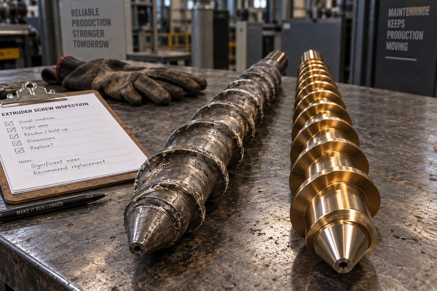
Total Cost of Ownership for Extruder Screw and Barrel Systems
Your purchasing department sees a line item: one extruder screw, $6,500. Another quote lands on the desk for a bimetallic PM tool steel screw at $18,000. The cheaper option wins every time—unless someone reframes the question. The real cost of an extruder screw isn't what you pay at delivery. It's what you pay per operating hour over its entire service life, including every dollar lost to downtime, scrap, and quality degradation while that screw slowly wears out. Whether you're running a davis standard extruder, a KraussMaffei twin-screw compounder, or a Chinese-built single-screw line, the economic math works the same way—and it almost always favors better metallurgy over cheaper purchase price.
Beyond Purchase Price: Per-Hour Economics of Screw Materials
Think of screw cost in three layers, not one:
- Purchase price divided by service hours — A $6,500 nitrided 4140 screw lasting 4,000 hours costs $1.63 per operating hour. An $18,000 CPM 10V screw lasting 20,000 hours costs $0.90 per hour. The premium screw is 45% cheaper on a per-hour basis despite costing nearly three times more upfront.
- Allocated downtime cost per changeout — Every screw swap requires shutting down the extruder, cooling the barrel, pulling the old screw, installing and aligning the replacement, reheating, and restarting to steady-state production. On a busy production line, that changeover window can consume 8 to 16 hours. If the line generates substantial revenue per hour of operation, a screw that requires replacement five times over the same interval that a premium screw runs once imposes four additional shutdowns—each one carrying its full burden of lost production.
- Scrap and quality loss attributed to worn screws — As flights erode, screw-to-barrel clearance increases. Melt leakage over worn flights reduces conveying efficiency, creates temperature inconsistencies, and degrades mixing uniformity. For color-sensitive products, iron contamination from a wearing screw discolors light-toned parts. These quality problems ramp up gradually over the screw's final third of useful life, often generating scrap costs that rival the screw's purchase price before anyone decides it's time to pull it.
Research from Spalding and Womer's cost analysis of commercial extrusion lines demonstrates just how dramatic the payback can be when screw investments are evaluated holistically. In one case study, a $8,400 optimized screw installed on an 88.9 mm blown film extruder increased throughput by 18%—from 130 kg/h to 154 kg/h—while reducing extrudate temperature by 20 degrees Celsius. The manufacturing cost saving was estimated at $91,000 per year, yielding a payback period of just 21 days. A second case study involving two optimized screws for a coextrusion foam sheet line—at a combined investment of $85,000—delivered a cost reduction of approximately $7.3 million per year by enabling a 43% increase in sheet output plus a 21% reduction in resin per sheet. The payback period? Just 2.1 days.
Those numbers reflect screw geometry optimization rather than material upgrades alone, but the principle transfers directly. A processor replacing a worn screw on a davis-standard extruder with a material upgrade from nitrided 4140 to bimetallic CPM 10V isn't just buying harder steel—they're buying four to five times the service interval, fewer shutdowns, more consistent melt quality, and reduced scrap accumulation across tens of thousands of operating hours. When those benefits are quantified against the incremental material cost, the payback timeline shrinks from years to weeks or even days on high-output lines.
The cheapest screw to buy is almost never the cheapest screw to own. Per-hour cost—not purchase price—is the metric that reveals whether your material selection is an investment or an expense.
This framework also explains why searching for a davis standard extruder for sale on the secondary market requires careful screw evaluation. A used machine may come with worn screws that need replacement, and the metallurgical choice you make for that replacement screw will determine whether the rebuild delivers years of reliable production or months of frustrating downtime. The original OEM screw specification was selected for someone else's resin and throughput—your application may demand an entirely different material class.
When to Rebuild, Recoat, or Replace
Not every worn screw needs to go in the recycling bin. Depending on the base material, the extent of damage, and your performance objectives, three end-of-life paths exist—each with different economics and different outcomes.
Rebuilding involves restoring a worn screw to its original dimensions through weld overlay on eroded flight crests, followed by machining and finish grinding. Common rebuild processes include PTA (plasma transferred arc) welding on the thread crest using a dual-alloy composition of nickel, tungsten, and cobalt, which can more than double the service life compared to the original nitrided surface. Rebuilding makes economic sense when the screw's base steel is sound—no fatigue cracks, no deep corrosion pitting beyond the flight surfaces—and when the cost of the rebuild plus the additional service life it buys compares favorably to a new screw purchase. It also offers a natural upgrade path: you can rebuild a 4140 screw with a tungsten carbide overlay that outperforms the original nitrided surface, effectively upgrading the material class without buying a completely new part.
Recoating applies advanced surface treatments—PVD coatings, ferritic nitrocarburizing, or hard chrome plating—to a screw that has moderate surface wear but remains dimensionally within tolerance. Surface hard chrome plating, for example, improves product surface accuracy and plastic flowability while restoring a thin layer of wear-resistant material. Recoating is the least expensive option but also the most limited: it works only when dimensional loss is minimal and the base material hasn't been compromised by corrosion or thermal degradation.
Full replacement with upgraded metallurgy is the right call when the existing screw's base material was wrong for the application from the start—when failure analysis reveals that the wear mechanism demands a fundamentally different alloy class rather than a thicker coat of the same protection. It's also justified when the processor's resin or filler program has changed since the original screw was specified, making the old material obsolete regardless of its remaining dimensional life.
Key factors that influence the rebuild-vs-replace decision:
- Base material condition: Is the core steel free of fatigue cracks, deep corrosion pitting, and thermal softening? If so, rebuilding is viable. If not, the structural integrity is compromised and replacement is safer.
- Extent of dimensional loss: Weld buildup can restore flight OD, but severely worn root diameters or heavily eroded channel depths may exceed practical rebuild limits. Most refurbishment specialists recommend replacement when dimensional loss exceeds 15–20% of original flight height.
- Desired material upgrade: If failure analysis indicates a need to move from nitrided low-alloy steel to PM tool steel or a corrosion-resistant stainless, rebuilding the old base with an overlay may not achieve the required performance. A new screw from the target material class delivers a clean baseline.
- Barrel condition: A rebuilt screw installed in a badly worn barrel will wear faster than expected because the enlarged bore increases clearance-driven leakage flow and shifts pressure loading onto flight tips. Evaluate the screw and barrel as a pair—if the barrel also needs rework, coordinating both ensures matched clearances at restart.
- Lead time and production urgency: Rebuilds typically take less time than manufacturing a new screw from scratch, especially for large-diameter or long L/D designs. If downtime cost is the dominant factor, a faster rebuild may win even when replacement would be metallurgically superior.
- Total cost of ownership over the next replacement cycle: Compare the rebuild cost plus projected service hours against the replacement cost plus its longer projected service hours. Include downtime, scrap, and quality costs in both scenarios. The option with the lower cost-per-operating-hour wins—not the option with the lower invoice.
The complexity of this decision—balancing base material condition, wear mechanism diagnosis, barrel matching, and per-hour economics—is exactly why working with a screw design partner who evaluates the full system pays dividends. NANHAIYA's Custom Screw Design Services evaluate material selection alongside screw geometry, barrel pairing, and surface treatment as an integrated system rather than isolated purchasing decisions. That holistic approach avoids the two most expensive mistakes processors make: over-specifying costly alloys in zones where standard steel would perform adequately, and under-specifying in zones where premature failure erases every dollar saved on the purchase order. Matching material to the full processing system—resin chemistry, filler loading, throughput target, barrel condition, and replacement economics—is where total cost optimization actually happens.
With the economic framework in place and the rebuild-versus-replace logic clarified, the remaining challenge is practical: how do you synthesize all of the metallurgical, resin-matching, and cost variables covered throughout this article into a step-by-step decision process you can apply the next time a screw needs specifying?
How to Choose the Right Screw Material for Your Extrusion Operation
Metallurgy, heat treatment, resin chemistry, failure analysis, zone-specific strategies, total cost of ownership—every section of this guide has added another variable to the plastic extruder screw material decision. That's a lot of moving parts. So how do you pull it all together into a clear, repeatable process the next time you need to specify a screw for a new extrusion barrel or replace a worn one on an existing line?
The answer is a structured decision sequence that forces you to evaluate each variable in the right order. Skipping steps—or tackling them out of sequence—is how processors end up with a screw that's metallurgically impressive on paper but mismatched to their actual production environment. The checklist below distills everything covered in this article into six actionable steps you can apply whether you're running us extruders, European machines, or Asian-built lines.
A Step-by-Step Material Selection Checklist
- Identify the primary resin and filler system. Start with the polymer you run most often, including its full additive package. A "glass-filled nylon" spec is not detailed enough—you need to know whether it's 15% short fiber or 50% long fiber, whether it contains mineral co-fillers, and whether flame-retardant additives introduce corrosive byproducts. The filler type, loading percentage, and particle hardness set the baseline severity for your screw's working environment.
- Classify the dominant wear mechanism. Is the primary threat abrasive (hard fillers scoring flight surfaces), corrosive (acidic decomposition gases attacking the metal), thermal (sustained high temperatures softening the steel), or a combination? Review your existing screw's wear patterns using the diagnostic guide from the failure analysis section. If you're specifying for a new line, use the resin-to-material matching table to predict the most likely mechanism. Misclassifying the wear mode here leads to selecting a material that solves the wrong problem.
- Determine the processing temperature range and required hot-hardness. Check your barrel zone setpoints, but don't stop there. Frictional heating at flight tips—especially under high screw speed or viscous resin conditions—can push localized metal temperatures well above the nominal barrel setting. Your screw steel's tempering curve must show stable hardness retention at or above the highest realistic service temperature, not just the controller setpoint.
- Evaluate the barrel extruder material and lining to ensure matched system performance. A screw doesn't wear in isolation. The barrel liner is its mating surface, and the hardness differential between the two determines which component sacrifices material first. If you're upgrading screw metallurgy, verify that the extrusion barrel liner is equally capable—or plan to upgrade both. Thermal expansion coefficients also need to match, particularly for high-temperature engineering polymers where CTE mismatches cause seizing.
- Calculate your acceptable replacement interval and target cost-per-operating-hour. Define what "good enough" looks like economically. How many operating hours between screw changes does your production schedule require? What does each changeover cost in lost output? Plug those numbers into the per-hour cost framework: purchase price divided by service hours, plus downtime cost per changeout, plus scrap and quality losses from worn-screw degradation. This calculation often reveals that a premium material costing two to three times more upfront delivers a significantly lower per-hour cost over its service life.
- Select the base material grade and surface treatment combination. Only after completing steps one through five do you choose the actual steel grade and hardening process. Match your answers to the material spectrum and treatment tables presented earlier in this article. For abrasive-dominant applications, prioritize carbide volume and hardness—PM tool steels or bimetallic tungsten carbide overlays. For corrosive-dominant challenges, prioritize chromium content and chemical barrier coatings—stainless steels, nickel-alloy bimetallics, or FNC treatments. For thermal-dominant environments, prioritize secondary hardening capability—H13 or high-speed steels tempered above service temperature. For combined mechanisms, layer your defenses: a corrosion-resistant base steel with an abrasion-resistant surface overlay, for example.
This sequence works because it mirrors how wear actually develops in service. The resin and filler dictate the attack. The temperature range determines whether the steel can hold its ground. The barrel pairing ensures the system works as a unit. The economics filter out over-engineered solutions that waste budget and under-engineered ones that waste production time. And the final material selection—grounded in all that context—targets the actual threat instead of guessing.
Getting Expert Help With Complex Material Decisions
For straightforward applications—unfilled polyolefins on a standard single-screw line—the checklist above may be all you need. But real-world extrusion rarely stays simple for long. Processors switching from commodity resins to glass-filled engineering compounds, commissioning new lines for corrosive PVC formulations, or scaling up high-temperature PEEK production face multi-variable decisions where the interactions between screw geometry, barrel design, surface treatment, and material chemistry create dozens of possible combinations. Picking the wrong one doesn't just cost a screw—it costs months of suboptimal output while you diagnose the mismatch and re-specify.
This is where catalog selection reaches its limit and engineering support becomes a practical necessity. A screw design partner who works across the full decision matrix—from metallurgy and heat treatment to resin-material matching and total cost optimization—can evaluate your specific polymer, throughput target, barrel condition, and production economics as an integrated system. NANHAIYA's Custom Screw Design Services operate exactly in this space, helping processors match screw geometry, barrel design, material selection, and surface treatment to specific polymers and output requirements. Rather than defaulting to a mid-range alloy and hoping for the best, you get a recommendation calibrated to your actual wear mechanism, your actual processing temperatures, and your actual cost-per-hour targets.
That calibration matters most when the stakes are highest: high-filler-load compounding where a wrong material choice means replacing screws every quarter, corrosive resin processing where pitting failures can contaminate product within weeks, or high-value production lines where every hour of unplanned downtime carries significant financial consequences. In those scenarios, the cost of expert material selection is trivial compared to the cost of getting it wrong twice.
The right screw material is not the hardest or most expensive option available—it is the one precisely matched to your resin, your process, and your production economics.
Every section of this guide has built toward that single principle. The metallurgy explains why materials perform differently. The heat treatment section shows how surface engineering amplifies base steel capability. The resin-matching tables tell you where each material class belongs. The failure analysis teaches you what went wrong last time. And the cost framework proves when a premium investment pays for itself. Apply them together—using the six-step checklist as your roadmap—and your next screw specification won't be a guess. It will be an engineering decision backed by evidence, matched to your process, and justified by the economics that actually matter.
Frequently Asked Questions About Plastic Extruder Screw Materials
1. What is the most common material used for plastic extruder screws?
AISI 4140 chromium-molybdenum alloy steel is the most widely used base material, accounting for roughly 80% of all installed extruder screws worldwide. When gas or ion nitrided, it achieves surface hardness of 55-62 HRC while maintaining a tough core that handles torsional loads. However, 4140 is best suited for unfilled commodity polymers like LDPE, HDPE, and PP. Processors running glass-filled engineering resins, corrosive PVC, or high-temperature polymers like PEEK should consider upgraded material classes such as D2 tool steel, CPM 10V powder metallurgy steel, or corrosion-resistant 17-4 PH stainless steel. A screw design partner like NANHAIYA can evaluate your specific resin, filler load, and throughput to recommend the most cost-effective material rather than defaulting to a generic 4140 specification.
2. How do I choose between a nitrided screw and a bimetallic screw?
The decision hinges on your dominant wear mechanism and total cost of ownership. Nitrided screws — typically 4140 or 38CrMoAlA with a 0.2-0.7 mm hardened case — perform well for unfilled or lightly filled commodity resins where abrasion and corrosion are minimal. They cost less upfront and suit moderate-duty applications. Bimetallic screws pair a tough steel core with a wear-resistant overlay such as tungsten carbide or nickel-boron alloy applied to flight surfaces. They cost roughly two to three times more but last two to five times longer in abrasive or corrosive environments, delivering a significantly lower cost per operating hour. Choose bimetallic when processing glass-filled compounds above 20% loading, corrosive resins like PVC, or any application where frequent screw replacements disrupt production schedules.
3. What screw material should I use for processing PVC?
PVC releases hydrochloric acid during thermal processing, which aggressively attacks nitrided steel surfaces and standard tool steels lacking sufficient chromium. For PVC extrusion, chromium-rich stainless steels like 17-4 PH (16% Cr) or nickel-alloy bimetallic linings with Colmonoy 56 or 83 coatings provide the corrosion barrier that standard materials cannot. Ferritic nitrocarburizing (FNC) applied to the transition zone — where off-gassing peaks — adds a chemical barrier layer. Screw design authority Tim Womer specifically recommends 17-4 PH for screws under 35 mm diameter in PVC service. The key is pairing corrosion-resistant screw metallurgy with a compatible barrel liner to prevent tribocorrosion, where mechanical wear and chemical attack combine to cause accelerated damage far worse than either mechanism alone.
4. Can a worn extruder screw be rebuilt instead of replaced?
Yes, rebuilding is often viable and economical when the base steel remains structurally sound — free of fatigue cracks, deep corrosion pitting, and thermal softening. Common rebuild methods include PTA welding with nickel-tungsten-cobalt alloys on eroded flight crests, which can more than double service life compared to the original nitrided surface. Rebuilding also offers a natural upgrade path: a worn 4140 screw can be restored with tungsten carbide overlays that outperform its original surface. However, replacement is the better choice when dimensional loss exceeds 15-20% of original flight height, when the base steel is compromised by corrosion or fatigue, or when failure analysis reveals that a fundamentally different alloy class is needed. Always evaluate the barrel condition simultaneously, since installing a rebuilt screw in a badly worn barrel accelerates re-wear.
5. Why do powder metallurgy tool steels outperform conventional tool steels in extruder screws?
Powder metallurgy (PM) steels like CPM 10V achieve superior wear resistance through uniform carbide distribution that is physically impossible in conventionally cast steels. During PM processing, molten steel is atomized into fine powder particles that cool almost instantly, producing carbides in the 1-5 micron range with no banding or clustering. Conventional tool steels like D2 develop primary carbides larger than 10 microns that cluster in bands, creating weak spots prone to chipping. The practical result is that PM screw flights wear evenly and predictably rather than losing material in random chunks. Standardized abrasion testing shows CPM 10V outperforming D2 by three to five times, and in production environments processing 40-60% mineral-filled compounds, CPM 10V screws routinely exceed 20,000 hours of service. The raw material costs 2.5 to 4 times more than D2, but per-hour economics strongly favor PM grades in high-abrasion applications.
Written by
Nanhaiya Technical Team
Zhoushan Nanhaiya Plastic Machinery Co., Ltd.
The Nanhaiya technical team supports screw and barrel manufacturing projects through application review, technical communication, custom manufacturing coordination, and production and quality control.
Discuss Your Application
Related Articles
More insights on screw barrel technology and plastics processing.
Your Extruder Feeding Instability Isn't Random — Here's Why
Oct 22, 2026
Extruder feeding instability causes surging output and scrap. Learn the 6 root causes, polymer-specific fixes, wear diagnostics, and preventive protocols.
Read Article
Parallel Twin Screw Extruder for Compounding Demystified: Lab to Line
Oct 21, 2026
Learn how a parallel twin screw extruder for compounding works—from screw element design and zone configuration to lab-to-production scale-up and process optimization.
Read Article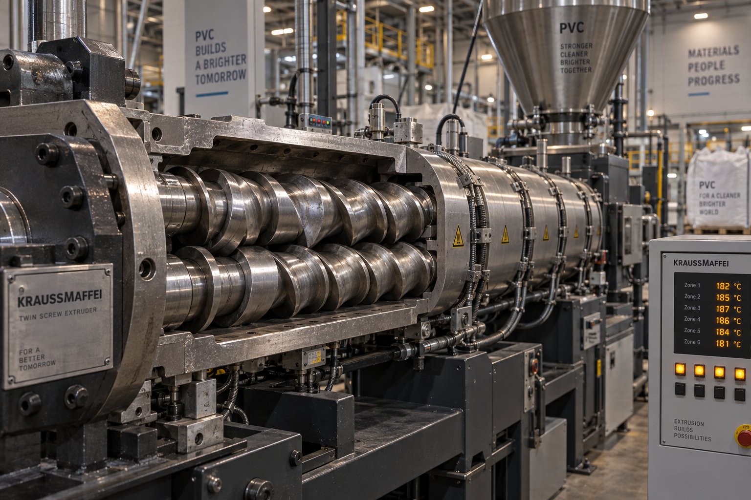
Twin Screw Extruder for PVC: The Setup Mistake Draining Profit
Oct 21, 2026
Learn how to match twin screw extruder configurations to PVC applications. Covers conical vs parallel, counter-rotating vs co-rotating, wear management, and troubleshooting.
Read ArticleLooking for something else?
Search by material, symptom or product and jump straight to the relevant page.
These are navigation suggestions based on keyword matching — not a quotation, not a delivery commitment, and not a substitute for engineering review. Final specification is confirmed by our engineers against your drawings and processed material.
Need help with screw barrel selection?
Share your machine model, processed material and application. Our team can help with pricing and technical support.