

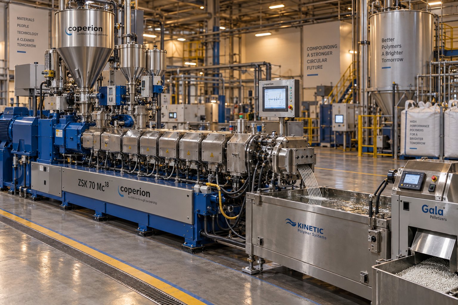
What Is a Parallel Twin Screw Extruder and Why It Leads Compounding
Imagine two identical screws spinning side by side inside a barrel with a cross-section shaped like a figure eight. That simple mental picture captures the core of one of the most important machines in polymer processing. Yet understanding exactly why this geometry dominates modern compounding requires a closer look at what sets it apart.
A parallel twin screw extruder for compounding consists of two equal-diameter screws rotating within a figure-eight barrel bore, engineered specifically for intensive mixing, homogenization, and pelletizing of polymers. Its modular barrel and screw construction allow process engineers to configure distinct functional zones—feeding, melting, mixing, venting, and pressure build-up—within a single machine.
Defining the Parallel Twin Screw Extruder
The defining feature of this twin screw extruder is geometric consistency: both screws share the same diameter from the feed end all the way to the discharge. This stands in direct contrast to conical designs, where screws taper from a larger diameter at the inlet to a smaller one at the outlet. Equal diameters along the full length mean every barrel segment and every screw element is interchangeable within its size class, giving engineers the freedom to rearrange processing zones like building blocks.
Barrels are built from modular segments—typically four to five length-to-diameter ratios each—that bolt together in sequence. Each segment can serve a different purpose: a solid barrel section for high-pressure mixing, an open port for side feeding additives, or a vented section for removing moisture and volatiles. The screws themselves are assembled from individual elements—conveying flights, kneading blocks, and mixing discs—slid onto a common shaft. This modularity is what makes twin screw extrusion so adaptable across hundreds of formulations and resin systems.
Why Parallel Geometry Dominates Compounding
Among twin-screw extruders used in plastics, the parallel configuration has become the undisputed industry standard for compounding. The reasons are practical. Its modular screw design delivers both dispersive and distributive mixing intensity that single screw machines simply cannot match—single screw extruders rely on drag flow and are primarily forming devices, not compounding extruders. Conical twin screw designs, while effective for specific tasks like PVC dry-blend processing, lack the flexibility to reconfigure zones or scale throughput as freely.
Parallel designs also scale predictably. A formulation developed on a small-diameter lab machine can be transferred to a production-scale line by maintaining geometric similarity and matching energy input. Combined with continuous processing capability and high screw speeds reaching 1,200 rpm on modern platforms, these machines handle everything from color masterbatch to glass-fiber-reinforced engineering plastics.
The sections ahead dive deep into the mechanics behind this versatility—rotation modes, screw element selection, zone-by-zone processing, and the path from laboratory development to full-scale production. Think of what follows as a process-engineering resource built to sharpen your understanding of the parallel twin screw extruder at every level of detail.
Co-Rotating vs Counter-Rotating Parallel Twin Screw Extruders
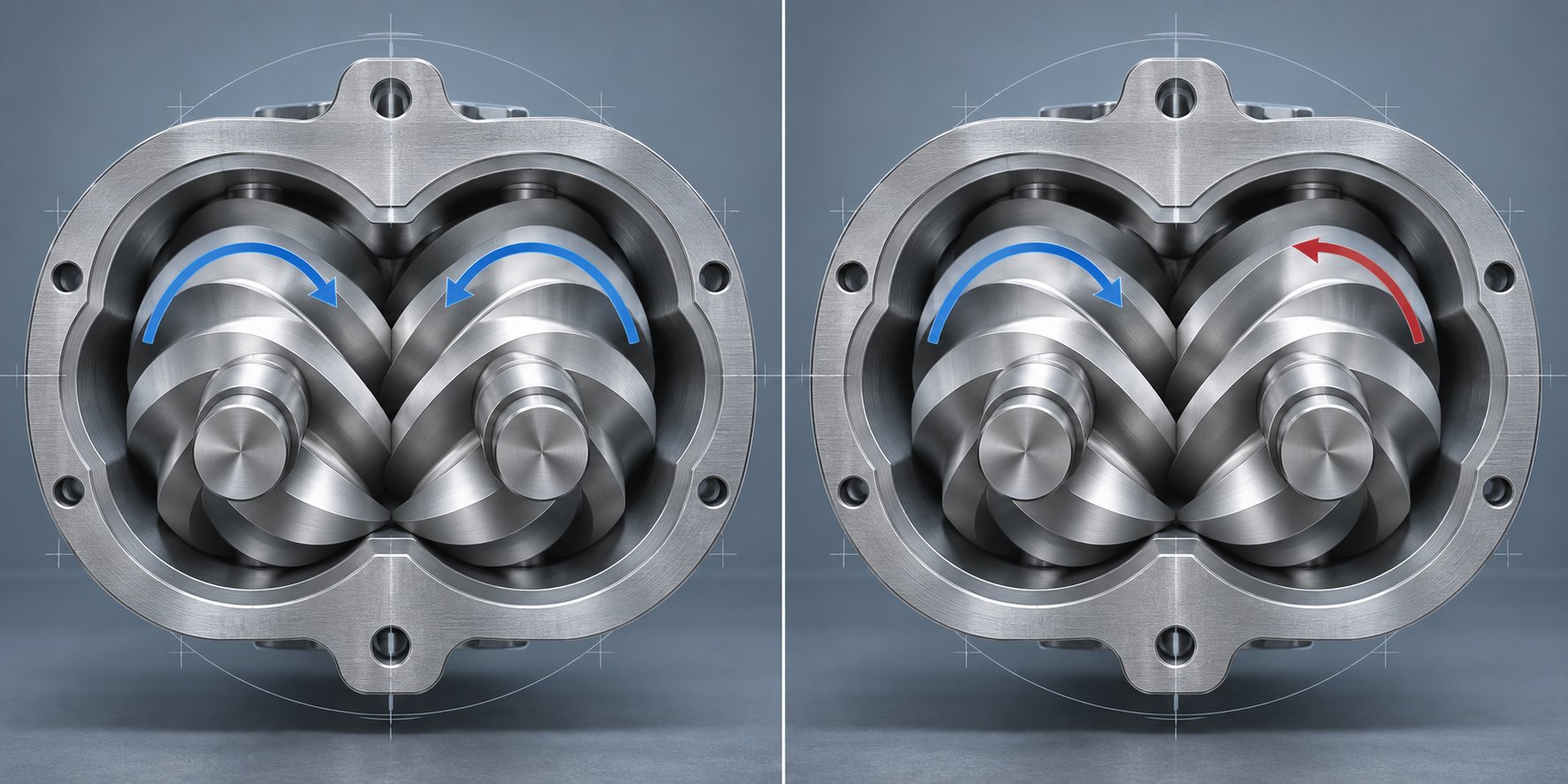
Two screws spinning inside the same barrel can move in the same direction or in opposite directions—and that single difference reshapes everything about how material flows, mixes, and exits the machine. Choosing between a co-rotating twin screw extruder and a counter-rotating design is one of the first decisions a process engineer faces, so understanding the mechanics behind each configuration is essential.
Co-Rotating Intermeshing Screws
In a co-rotating twin screw extruder, both screws turn in the same direction while maintaining a fully intermeshing geometry. Picture the material being forcibly handed off from one screw flight to the next at the intermeshing zone—it follows a figure-eight path as it travels downstream, repeatedly crossing between screws. This constant transfer creates intense shear fields both between the screws and between each screw and the barrel wall.
The real advantage here is self-wiping action. Because both screws rotate the same way, one screw's flight continuously sweeps the surface of the other, preventing material from sticking or stagnating. You'll notice this matters enormously for heat-sensitive polymers: with virtually no dead zones, every particle experiences a similar thermal and shear history. The result is a narrow residence time distribution that minimizes degradation risk while delivering both dispersive and distributive mixing at high intensity.
These characteristics explain why co-rotating designs dominate compounding operations. From filler-loaded engineering plastics and polymer alloys to nanocomposite formulations, the co-rotating configuration provides the mixing versatility that modern compound development demands.
Counter-Rotating Intermeshing Screws
Flip one screw's rotation direction, and the physics change fundamentally. In a counter-rotating twin screw extruder, the screws turn in opposite directions, drawing material inward at the intermeshing zone and advancing it through a series of enclosed C-shaped chambers. This geometry creates a strong positive-displacement pumping action—material is trapped between flights and pushed forward with minimal back-mixing.
Rather than the high-shear environment of co-rotating machines, counter-rotating designs rely on a calendering effect at the intermeshing region. Material undergoes compressive and elongational deformation under relatively gentle conditions, keeping shear heating low. The trade-off? Lateral exchange between screw channels is limited, so distributive mixing is weaker, and self-wiping capability is reduced—meaning dead zones can form near the channel roots.
Where does this configuration shine? Rigid PVC processing is the classic example. PVC's low decomposition temperature and poor melt flow make it a poor candidate for high-shear co-rotating machines. Counter-rotating twin screw extruders handle PVC pipes, sheets, and profiles by operating at high fill levels and low speeds while suppressing temperature rise. Reactive extrusion processes requiring gentle, controlled mixing also benefit from this approach.
Choosing the Right Rotation for Your Application
Selecting between these two configurations comes down to matching machine characteristics to your material and process goals. The table below puts the key differences side by side:
| Parameter | Co-Rotating | Counter-Rotating |
|---|---|---|
| Mixing Intensity | High — both dispersive and distributive | Moderate — stronger dispersive, weaker distributive |
| Shear Rate | High, adjustable via screw speed and element design | Lower, governed by calendering effect |
| Self-Wiping Capability | Excellent — minimal dead zones | Limited — dead zones possible near channel roots |
| Conveying Mechanism | Drag flow with positive-displacement component | Strong positive-displacement pumping |
| Residence Time Distribution | Narrow and uniform | Broader, longer average residence time |
| Typical Compounding Applications | Filled compounds, polymer blends, masterbatch, reactive extrusion, nanocomposites | PVC dry-blend processing, profile extrusion, gentle reactive processes |
Industry consensus holds that the vast majority of compounding lines—widely estimated at around 90 percent—use co-rotating configurations. The reason is straightforward: compounding almost always demands intensive mixing, modular screw flexibility, and the narrow residence time distribution that co-rotating twin screw extruders deliver. Counter-rotating machines fill a valuable niche, but for general-purpose polymer compounding, co-rotating twin screw extruders remain the standard choice.
Of course, knowing which direction the screws turn is only half the story. The real engineering challenge lies in understanding how intermeshing geometry, self-wiping profiles, and sequential barrel zones work together to transform raw ingredients into a finished compound—a question that leads directly into the working principle of the machine itself.
Working Principle of the Parallel Twin Screw Extruder in Compounding
Rotation direction determines how material moves between screws—but the real question is: what happens to every polymer particle from the moment it enters the feed throat until it exits as a fully compounded melt? Understanding the twin screw extrusion process at this level turns abstract geometry into practical process control. Let's walk through the mechanics step by step.
Intermeshing Geometry and Self-Wiping Profiles
Inside the figure-eight bore of the extrusion barrel, the two screws maintain extremely tight clearances against each other and against the barrel wall. These closely intermeshing profiles—identified in screw engineering as Erdmenger profiles—are the foundation of everything the machine does well.
Imagine a polymer pellet entering the feed zone. As the screws rotate, the flight of one screw continuously sweeps into the channel of the other. This tight interaction does two things simultaneously. First, it physically prevents material from sitting still. Any melt that begins to cling to a screw surface is scraped off by the opposing flight within a fraction of a revolution. This self-wiping action eliminates dead zones where degraded polymer could accumulate and contaminate your product.
Second, intermeshing geometry creates what engineers call positive displacement conveying. Unlike a single screw extruder—where material advances primarily through drag flow, relying on friction between the barrel wall and the melt—the twin screw design traps material in enclosed or semi-enclosed pockets between flights and physically pushes it forward. The practical benefit? Conveying becomes largely independent of the material's viscosity or friction characteristics. Whether you're processing a low-viscosity nylon melt or a highly loaded mineral compound, each extruder screw rotation advances a predictable volume of material downstream.
This positive displacement mechanism also produces a narrow residence time distribution. Every particle spends roughly the same amount of time inside the machine, experiencing nearly identical thermal and shear histories. For compounding, that uniformity is critical—it means consistent additive dispersion, uniform color development, and minimal risk of localized overheating.
Functional Zones Along the Barrel
A parallel twin screw extruder doesn't perform one task along its entire length. Instead, it's organized into sequential processing zones, each created by specific combinations of barrel sections and screw elements. Think of the barrel as a stage, and the screw elements as actors playing different roles at different positions.
- Solids Conveying Zone (Feeding) — Raw polymer pellets, powder, or flake enter through the feed throat and land in deep-flighted, large-pitch conveying elements. These elements grip the solid material and move it forward quickly without applying significant compression. The barrel in this zone is often left unheated or cooled to prevent premature melting that could bridge the feed opening. Starve feeding—where the feeder controls the feed rate rather than gravity—is standard practice here to keep this zone partially filled and avoid surging.
- Melting and Plastication Zone — As material advances, barrel heaters raise the temperature while screw elements transition from large-pitch conveyors to tighter-pitch designs and initial kneading blocks. Polymer begins to melt through a combination of conducted heat from the barrel wall and intense mechanical shear generated by the intermeshing screw extrusion action. Unlike single screw machines—where melting relies on a slow drag-induced film developing against the barrel—the twin screw design melts material rapidly through dispersive energy input across every particle. The result is a faster, more complete melt with fewer unmelted particles reaching downstream zones.
- Mixing Zone — Here is where compounding truly happens. Kneading blocks and specialized mixing elements deliver both dispersive mixing (breaking down agglomerates of pigments, fillers, or additive clusters) and distributive mixing (spreading those components evenly throughout the polymer matrix). The geometry of each element—disc width, stagger angle, and forward or reverse orientation—determines how aggressively material is sheared and rearranged. Multiple mixing sections can be placed along the barrel, separated by conveying elements that relieve pressure and allow temperature to stabilize.
- Venting and Degassing Zone — Moisture, trapped air, residual monomers, and other volatiles degrade compound quality if left in the melt. To remove them, the screw profile transitions back to open conveying elements that reduce pressure and increase free surface area. A reverse-pitch element or reverse kneading block upstream creates a melt seal, preventing the low-pressure vent zone from drawing melt backward. Vacuum is applied through an open barrel port, pulling volatiles out of the partially filled melt. For moisture-sensitive engineering resins or recycled feedstocks with high volatile content, multiple vent zones can be configured along the extrusion barrel.
- Pressure Build-Up Zone (Metering) — In the final section before the die, tight-pitch conveying elements compress the fully compounded melt to build stable, consistent pressure. This pressure drives the melt through the die plate, screen pack, or pelletizing head. Uniform pressure here is essential—fluctuations translate directly into inconsistent strand diameter, pellet weight variation, or surface defects on the final product.
Each of these zones can be lengthened, shortened, or reconfigured simply by rearranging barrel segments and swapping screw elements on the shaft. That modular flexibility is what allows a single machine platform to process formulations as different as carbon-black-loaded conductive compounds and glass-fiber-reinforced polyamides.
How These Principles Translate to Superior Compounding
So why does all of this matter when you're standing next to a running line, evaluating compound quality? The connection between working principle and real-world outcomes is direct:
- Narrow residence time distribution reduces thermal degradation. Because positive displacement conveying moves every particle forward at a similar rate, heat-sensitive polymers like PBT or POM can be compounded with minimal molecular weight loss. There are no stagnant pockets where resin sits and cooks.
- Self-wiping action prevents material hang-up. During color changes or recipe transitions, the machine purges quickly. Contamination from the previous batch is minimized because the intermeshing screw profiles leave virtually no residual material clinging to surfaces. This translates to less scrap, shorter changeover times, and higher effective uptime.
- Modular zone design allows independent optimization. A process engineer can intensify the mixing zone for a heavily filled formulation without altering the feeding or venting behavior. Conversely, a reactive extrusion recipe that needs gentle mixing but aggressive degassing can be accommodated on the same machine by reconfiguring the screw profile and barrel layout.
These principles aren't theoretical abstractions—they're the engineering reasons behind the parallel twin screw extruder's dominance in compounding. Every specification on a data sheet, from specific torque density to free volume, traces back to how effectively these zones and mechanisms can be implemented for a given application.
Yet the zones themselves only perform as well as the individual elements assembled on each shaft. The real art of compounding lies in selecting and sequencing the right conveying flights, kneading blocks, and mixing elements to create a screw profile tailored to your exact formulation—a subject that deserves its own detailed treatment.
Screw Element Design and Modular Profile Configuration
Every functional zone described earlier—feeding, melting, mixing, venting, pressure build-up—is created by the specific elements mounted on the screw shaft. Swap a kneading block for a conveying flight, change a disc width, or reverse the pitch direction, and you fundamentally alter how your compound develops inside the extruder screw barrel. That makes element selection the most powerful lever a process engineer has. So what are the options, and how do you put them together?
Types of Screw Elements for Compounding
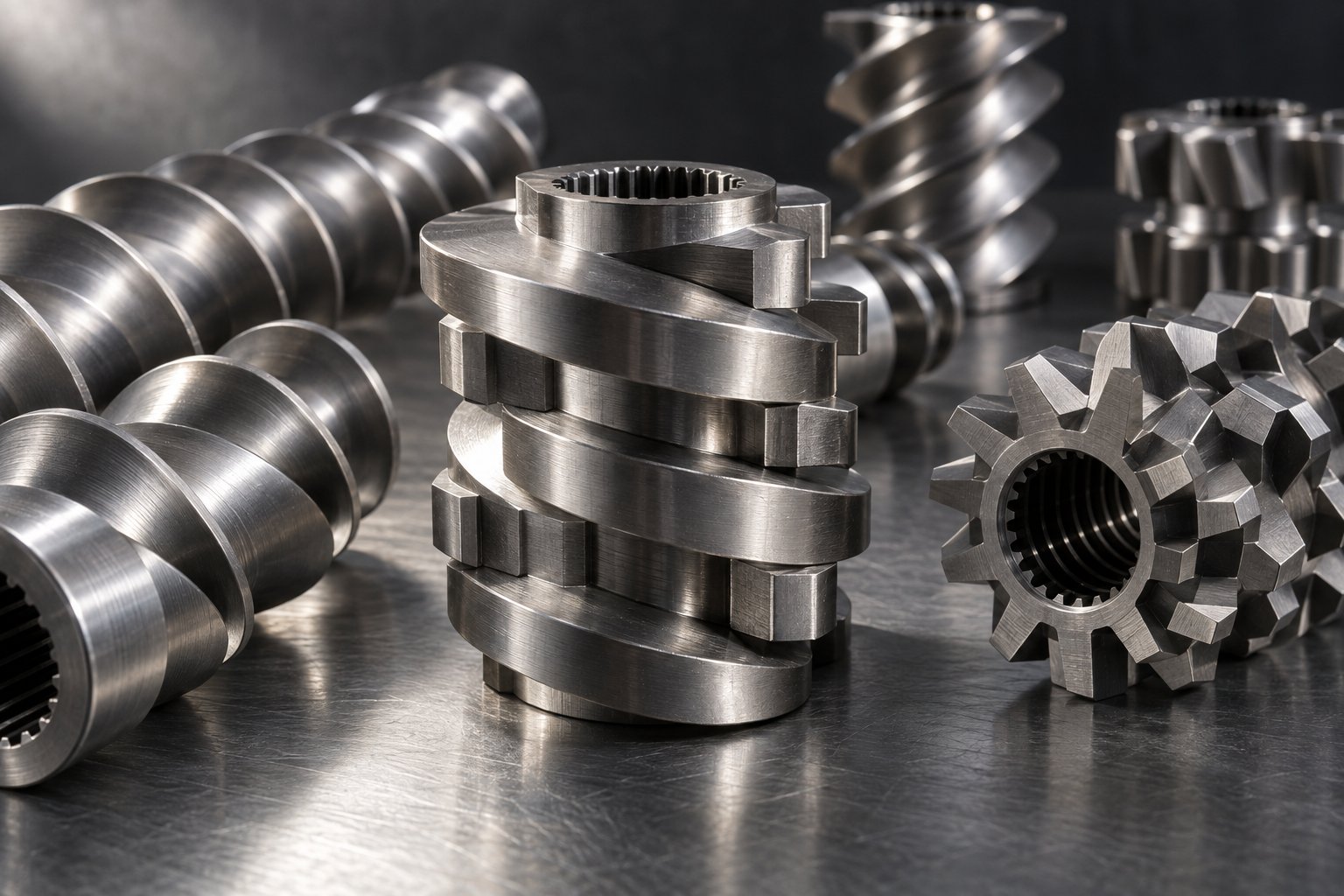
All elements used in a parallel twin screw extruder fall into a handful of fundamental categories. Each serves a distinct purpose, and combining them is what transforms a bare shaft into a purpose-built compounding tool. Here is a breakdown of the core element types:
- Conveying elements (forward pitch) — These are helical flights that transport material downstream. A large-pitch conveying element moves bulk material quickly with minimal shear, making it ideal for the extruder feed barrel zone where pellets or powder first enter the machine. As pitch decreases, fill level and residence time increase, producing more compression and pressure. Think of pitch as a throttle: wide open for fast transport, narrowed down when you need material to spend more time in a specific zone. NC State Extension research notes that conveying ability decreases with decreasing pitch, and channel depth follows a similar gradient—deepest in the conveying zone, shallowest in metering.
- Kneading blocks — These are the workhorses of mixing. A kneading block consists of a series of lobed discs stacked at offset angles (stagger angles) along a short segment. The disc width and stagger angle determine whether the element promotes distributive or dispersive mixing:
- Narrow-disc kneading blocks slice through the melt in a scissoring action, dividing and recombining the material to spread additives, pigments, and minor components evenly—this is distributive mixing, perfect for color dispersion and additive blending.
- Wide-disc kneading blocks plow through the polymer, creating a pool of melt in front of each disc and generating high shear stress. This is dispersive mixing—essential for breaking down agglomerates of carbon black, deagglomerating mineral fillers, and reducing particle clusters to their primary size.
- Medium-disc kneading blocks provide a balanced combination of both mixing modes, suitable for general-purpose compounding where neither extreme dominates.
- Distributive mixing elements — Toothed or gear-type elements feature rows of interlocking teeth rather than continuous flights. Material passes through the gaps between teeth, getting split, reoriented, and recombined with minimal shear stress. These elements are well suited for gentle homogenization—situations where you need uniform distribution without risking fiber breakage or excessive melt temperature rise.
- Reverse-pitch conveying elements — Identical in geometry to standard conveying elements but with opposite-hand helix, these push material backward against the main flow. Their primary role is creating melt seals upstream of vent ports. By forcing material to build up and fully fill the channel, reverse elements prevent vacuum from pulling melt into the degassing zone. Their length is typically kept shorter than one screw diameter to avoid extreme pressure peaks that could damage the twin screw and barrel assembly.
Building a Screw Profile for Specific Compounding Outcomes
Knowing what each element does individually is only the starting point. The real skill lies in sequencing elements along the shaft to build a functional screw profile that transforms raw ingredients into a finished compound. Imagine you're arranging the elements like words in a sentence—each one must follow logically from the last to tell a coherent processing story.
A generalized compounding screw profile typically follows this sequence:
- Forward conveying (large pitch) — Accepts raw material from the feeder and moves it into the barrel with minimal shear. This open geometry prevents bridging in the feed throat.
- Kneading block section for melting — A combination of medium- and wide-disc kneading blocks applies the mechanical energy needed to transition the polymer from solid pellets to a cohesive melt. Barrel heating assists, but the bulk of energy input comes from shear.
- Forward conveying for pressure relief — A short section of conveying elements reduces local pressure and allows melt temperature to stabilize before the next intensive zone. This pause prevents cumulative overheating.
- Intensive kneading for additive dispersion — A second kneading block section—often including neutral or reverse-stagger blocks—disperses fillers, pigments, or reinforcements into the melt. For a heavily loaded plastic extruder screw profile, this section might be longer and more aggressive than the melting zone.
- Reverse element for melt seal — A short reverse-pitch conveying element or reverse kneading block creates a fully filled zone that seals the upstream processing from the low-pressure vent section downstream.
- Open conveying for vacuum venting — Large-pitch conveying elements reduce fill level and expose maximum melt surface area beneath the vacuum vent port, allowing moisture and volatiles to escape efficiently.
- Metering conveying to die — Tight-pitch conveying elements compress the melt and build stable pressure to push it through the die plate or pelletizing head.
This sequence is a blueprint, not a rigid formula. Every formulation demands adjustments. A carbon black masterbatch might need an extended dispersive kneading section with 90-degree neutral blocks to break down stubborn agglomerates. A glass-fiber-reinforced compound, on the other hand, calls for a gentler mixing zone—primarily narrow-disc distributive elements—to preserve fiber length. As experienced compounding engineers note, screw design is a blend of science and art, and most mixing sections work best when they end with a neutral or reverse element to ensure a high degree of fill that makes mixing efficient rather than allowing the polymer to be whipped through an empty channel.
Screw profile optimization is inherently iterative. Process engineers run trials, evaluate compound quality—dispersion rating, melt temperature, mechanical properties—and adjust element sequences to find the sweet spot between mixing intensity, throughput, and thermal load. The modularity of the twin screw and barrel system makes this iteration practical: reconfiguring a screw profile on a modern extruder takes hours, not weeks.
Of course, the screw profile is only one piece of a larger puzzle. The elements do their job inside a process chain that begins with precise feeding of raw materials and ends with pelletizing a finished compound—a complete workflow where every upstream and downstream decision shapes the quality of the final product.
The Complete Compounding Line: From Raw Material Feeding to Finished Pellets
A perfectly configured screw profile means little if the material entering the barrel is inconsistent or if the melt exiting the die isn't properly pelletized. The extruder is the heart of a compounding operation, but it doesn't work alone. Every stage—from how raw ingredients are metered into the feed throat to how strands are cooled and cut into pellets—directly shapes the quality, consistency, and economics of the final compound. Thinking of the extruder in isolation is a common mistake. Let's walk through the entire workflow so you can see how each link in the chain supports the next.
- Raw material preparation and feeding
- Melting, mixing, and degassing inside the extruder
- Die extrusion and melt filtration
- Cooling (water bath, air conveyor, or underwater chamber)
- Pelletizing (strand cutting, underwater cutting, or hot-face cutting)
- Classification, drying, and packaging
Raw Material Feeding and Dosing
Compounding starts before a single pellet touches the screw. The feeding system determines how accurately your recipe is maintained—batch after batch, hour after hour. Two fundamental approaches exist: volumetric feeding and gravimetric feeding.
A volumetric feeder delivers material at a set speed, assuming that the bulk density of the ingredient remains constant. That assumption works reasonably well for uniform pellets but breaks down quickly with powders, flakes, or recycled regrind that vary in density and flow behavior. Gravimetric feeders solve this problem by continuously weighing the material as it leaves the hopper and adjusting motor speed in real time to maintain a precise mass flow rate. For compounding, gravimetric feeders are the preferred choice because they deliver the accuracy needed to hold tight formulation tolerances—typically within ±0.5% repeatability at two standard deviations for pelletized polymers. That precision translates directly into recipe consistency, reliable mechanical properties, and full batch traceability.
Feeding isn't limited to the main feed throat. Many compounding formulations require ingredients to be introduced at different points along the barrel:
- Side stuffers — Twin-screw side feeders mounted partway down the barrel deliver fillers, glass fibers, and minerals directly into the melt. Why not add everything at the main feed throat? Because materials like glass fiber would be exposed to the full length of the screw profile, suffering excessive breakage and losing the very fiber length that gives the compound its mechanical strength. Similarly, high-loading mineral fillers fed at the main throat can overwhelm the conveying capacity of the feed zone and starve the extruder. By introducing these components downstream—after the polymer is already melted—you control shear exposure and preserve ingredient integrity.
- Liquid injection ports — Oils, liquid coupling agents, plasticizers, and liquid color concentrates can be pumped into the barrel through injection nozzles at precise locations. Positioning matters: inject a coupling agent too early and it may volatilize before reaching the filler; inject it too late and it won't have enough residence time to react at the filler surface.
One subtlety worth noting is that the side feeder itself can become a source of variation. As industry analysis from Plastics Technology points out, if a side feeder runs in starve-fed mode, feed-rate fluctuations from the upstream weigh feeder transfer directly into the extruder system. Running the side-feeder screws in a flooded condition—where material consistently covers the screws—helps decouple the primary feeder's variability from what actually enters the barrel.
Melting, Mixing, and Degassing Inside the Extruder
Once raw materials enter the barrel, the transformation from discrete ingredients to a homogeneous compound follows the zone-by-zone sequence covered earlier: solids conveying, melting through shear and conducted heat, intensive dispersive and distributive mixing through kneading blocks, and finally pressure build-up toward the die. Rather than repeating those mechanics, consider how the workflow context adds a practical layer.
Inside the twin-screw extruder machine, the melt is more than just hot polymer—it's a complex mixture of resin, fillers, pigments, stabilizers, and potentially moisture and trapped air. Degassing plays a critical role in producing a clean compound. Moisture left in the melt causes hydrolytic degradation in condensation polymers like polyamide and PET, weakening the final product. Residual volatiles can produce bubbles, surface defects, and odor in finished parts.
Vacuum venting addresses both problems. At the vent port, the screw profile transitions to open, partially filled conveying elements that expose maximum melt surface area. A vacuum pump pulls volatiles and moisture vapor out of the barrel through the open port while a melt seal upstream—created by a reverse element—prevents the vacuum from drawing melt backward. For formulations with high moisture content, such as recycled feedstocks or hygroscopic engineering resins, multiple vent zones can be configured along the barrel to stage the degassing progressively.
Barrel temperature control across all zones is equally important. Each barrel segment has independent heating and cooling capability, allowing engineers to set a precise thermal profile that matches the rheological needs of the formulation—higher temperatures in the melting zone, moderate temperatures through mixing, and sometimes reduced temperatures near the die to lower melt viscosity variations.
Downstream Equipment in the Compounding Line
What happens after the melt leaves the extruder barrel defines the final pellet form, quality, and throughput rate of the entire line. Downstream equipment is not an afterthought—it must be matched to the compound's properties and the production targets of the operation.
Die plates and strand dies sit at the extruder discharge, shaping the melt into continuous strands or directly into pellet-ready form. A melt filtration screen or screen changer is often placed between the extruder and the die to catch contaminants, gels, or undispersed agglomerates. For recycling applications where feedstock quality varies, continuous screen changers allow filter replacement without stopping the line.
From the die, the path to pellets diverges based on the pelletizing method selected. Each approach suits different materials and production scales:
- Water-cooled strand pelletizing — This is the most common setup for standard compounding operations. Molten strands exit the die, pass through a water bath for cooling, travel across an air knife to remove surface water, and then enter a strand pelletizer where rotating blades cut them into uniform cylinders. It's a straightforward, reliable process with relatively low capital cost. However, it typically requires an operator to guide strands through the water bath at startup, and throughput is limited by the number of die holes and strand-handling capacity.
- Underwater strand pelletizing — A step up in automation, this method uses water flow to carry strands through a helical water bath directly into the pelletizer, eliminating the need for manual strand threading. A centrifugal dryer separates pellets from water after cutting. This configuration is well suited for PET recycling, highly filled compounds, and materials with low strand strength that would break during manual handling.
- Underwater die-face pelletizing — Here, the melt is extruded through a die plate directly into a pressurized water chamber, where a rotating cutter shears the emerging melt into pellets that are instantly cooled and solidified. The result is near-spherical pellets with excellent uniformity and minimal fines. Underwater pelletizers excel in continuous, high-throughput production and handle sticky or soft formulations—like TPE and hot-melt adhesives—that would be difficult to strand-pelletize. The trade-off is higher capital investment and more complex maintenance due to the underwater cutting environment.
- Hot-face pelletizing (air or water cooled) — A cutter mounted directly on the die face cuts the melt as it emerges, with cooling handled either by forced air or a water ring. Air-cooled versions suit moisture-sensitive materials like biodegradable polymers where water contact must be avoided entirely. Water-cooled hot-face systems offer faster solidification but require a downstream centrifugal dryer to separate pellets from the cooling water.
Choosing the right pelletizing method is a balancing act. Strand pelletizing remains the workhorse for general-purpose compounding due to its simplicity and lower cost. Underwater die-face systems justify their investment on high-volume lines—particularly for masterbatch and engineering compound production—where continuous operation, pellet uniformity, and minimal operator intervention drive long-term economics. For a screw extruder granulator setup processing moisture-sensitive biopolymers, an air-cooled hot-face system may be the only viable option.
After pelletizing, the finished compound passes through classification screens to remove oversized or undersized particles, a centrifugal or fluidized-bed dryer to bring moisture content within specification, and finally into packaging or bulk storage systems. Automated sampling stations can pull pellets at set intervals for quality control testing—ash content, melt flow rate, color measurement—closing the loop between process and product.
Every piece of equipment in this chain, from the gravimetric feeder at the inlet to the pellet classifier at the outlet, interacts with every other piece. A feeder upset creates uneven filler loading that no amount of downstream screening can fix. A poorly matched pelletizer creates fines that clog pneumatic conveying lines. Viewing the compounding line as an integrated system—rather than focusing on the extruder alone—is what separates a reliable, high-quality operation from one that constantly chases problems.
With the full workflow mapped out, a natural question emerges: how does a parallel twin screw extruder stack up against the other machine types available to compounders? Understanding where each technology fits—and where it falls short—requires a direct, structured comparison.
Parallel vs Conical vs Single Screw Extruders for Compounding
Three fundamentally different screw extruder architectures compete for space on compounding plant floors: parallel twin screw, conical twin screw, and single screw. Each machine handles polymer differently, and picking the wrong one can mean fighting your equipment instead of optimizing your formulation. So how do they actually compare when the job is compounding?
Parallel Twin Screw vs Conical Twin Screw vs Single Screw for Compounding
Rather than relying on general impressions, the table below lines up the three technologies against the parameters that matter most to a process engineer evaluating a double screw extruder machine or a single screw alternative for a compounding application.
| Parameter | Parallel Twin Screw Extruder | Conical Twin Screw Extruder | Single Screw Extruder |
|---|---|---|---|
| Screw Geometry | Two equal-diameter screws, constant center distance, figure-eight bore | Two tapered screws converging toward discharge, angled center distance | One screw in a cylindrical bore |
| Dispersive Mixing | Excellent — adjustable via kneading block width, stagger angle, and screw speed | Moderate — limited by fixed screw geometry and lower speeds | Poor — restricted to barrier flights and static mixers with significant pressure-drop penalty |
| Distributive Mixing | Excellent — figure-eight flow path with full screw-to-screw material transfer | Moderate — C-shaped chamber flow limits lateral exchange | Poor — channel stratification prevents full turnover of melt |
| Throughput Range | Wide — from a few kg/h (lab scale) to 20,000+ kg/h (production scale) | Narrow — generally limited to low and mid-range outputs | Moderate — scalable for forming, but output drops sharply when mixing devices are added |
| Screw Speed Range | Up to 900–1,200 rpm on modern platforms | Typically 30–150 rpm | Typically 50–200 rpm |
| Modularity | Fully modular — interchangeable barrel segments and screw elements on splined shafts | Fixed — integrated one-piece screws, no element swapping | Limited — some modular mixing sections available, but core geometry is fixed |
| Shear Control | Highly adjustable — element selection, screw speed, and fill level all serve as independent controls | Limited — primarily controlled by screw speed and barrel temperature | Limited — high shear areas cause proportional output loss and melt temperature rise |
| Typical Compounding Applications | Filled compounds, polymer blends, masterbatch, engineering plastics, reactive extrusion, recycling | PVC dry-blend processing, wood-plastic composites, high-calcium-carbonate compounds | Simple color blending, single-polymer homogenization, forming and shaping (pipe, film, sheet) |
| Scalability | Excellent — geometric similarity enables lab-to-production scale-up | Limited — taper geometry constrains scaling options | Moderate — scales well for forming, poorly for compounding intensity |
A few takeaways jump out immediately. Single screw extruders are fundamentally forming machines. As Jim Frankland of Frankland Plastics Consulting explains, the single screw can't transfer the full channel of polymer from one screw to another—the mechanism that gives twin screws their mixing superiority simply doesn't exist. Attempts to add mixing sections create flow resistance, reduce output, and elevate melt temperature. For simple blending of a pre-compounded pellet with a small percentage of color concentrate, a single screw works fine. For actual compounding—dispersing fillers, breaking agglomerates, blending immiscible polymers—it falls short.
The conical twin screw extruder fills a real but narrower role. Its tapered geometry generates excellent pressure at low speeds, making it ideal for rigid PVC pipe and profile extrusion where gentle handling of heat-sensitive material matters more than mixing intensity. However, the one-piece screw design is fixed during manufacturing—you can't swap elements to adjust mixing zones or add venting sections for a different formulation. That inflexibility limits the conical twin-screw extruder to dedicated applications rather than the multi-product, multi-formulation environment where parallel machines thrive.
Where Each Technology Fits in the Processing Landscape
Thinking about which machine belongs where becomes straightforward once you match the technology to the task:
- Parallel twin screw extruders dominate polymer blending, filled compounds, masterbatch production, engineering plastics compounding, reactive extrusion, and recycling. Their modular design, intensive mixing, and scalable throughput make them the default choice for any operation processing multiple formulations or demanding tight quality specifications.
- Conical twin screw extruders remain the standard for dedicated PVC processing lines—rigid pipes, profiles, window frames, and flooring. Where a plant runs a single PVC formulation at steady state, the conical machine's torque efficiency and compact footprint offer real advantages.
- Single screw extruders serve best as downstream forming machines—producing film, sheet, pipe, and profiles from pre-compounded pellets. They're also adequate for simple letdown blending of masterbatch into carrier resin at the molding machine or converting line.
Internal batch mixers—Banbury-type or intensive mixers—still serve legacy rubber and some specialty polymer applications. Yet they lack the continuous processing advantages that a double screw extruder machine provides: consistent throughput, narrow residence time distribution, and inline degassing without batch-to-batch variability.
For process engineers and decision-makers evaluating compounding equipment, one factor often overlooked during the selection process is component quality. The best-designed machine architecture delivers inconsistent compounds if barrel liners wear unevenly, screw elements lose their tight intermeshing tolerances, or metallurgy doesn't match the abrasiveness of the materials being processed. Barrel and screw component quality directly impacts compound consistency and line uptime. Suppliers like NANHAIYA offer custom parallel twin screw barrels engineered for demanding compounding, recycling, and pelletizing applications—addressing the wear-resistance and dimensional precision requirements that production-scale lines demand.
Knowing which machine architecture to choose is the strategic decision. The tactical decisions—what compounds to run, how to optimize screw profiles for specific materials, and which applications truly exploit the parallel twin screw's capabilities—depend on understanding the full range of compounding tasks these machines are designed to handle.
Compounding Applications Best Suited to Parallel Twin Screw Extruders
A parallel twin screw extruder can process almost any thermoplastic formulation—but it truly earns its keep in applications where mixing intensity, modular flexibility, and tight process control separate acceptable results from outstanding ones. What kinds of compounding tasks push these machines to their full potential? The list is broader than many engineers realize.
- Polymer blending and engineering plastics compounding — immiscible blends, glass-fiber-reinforced and mineral-filled formulations
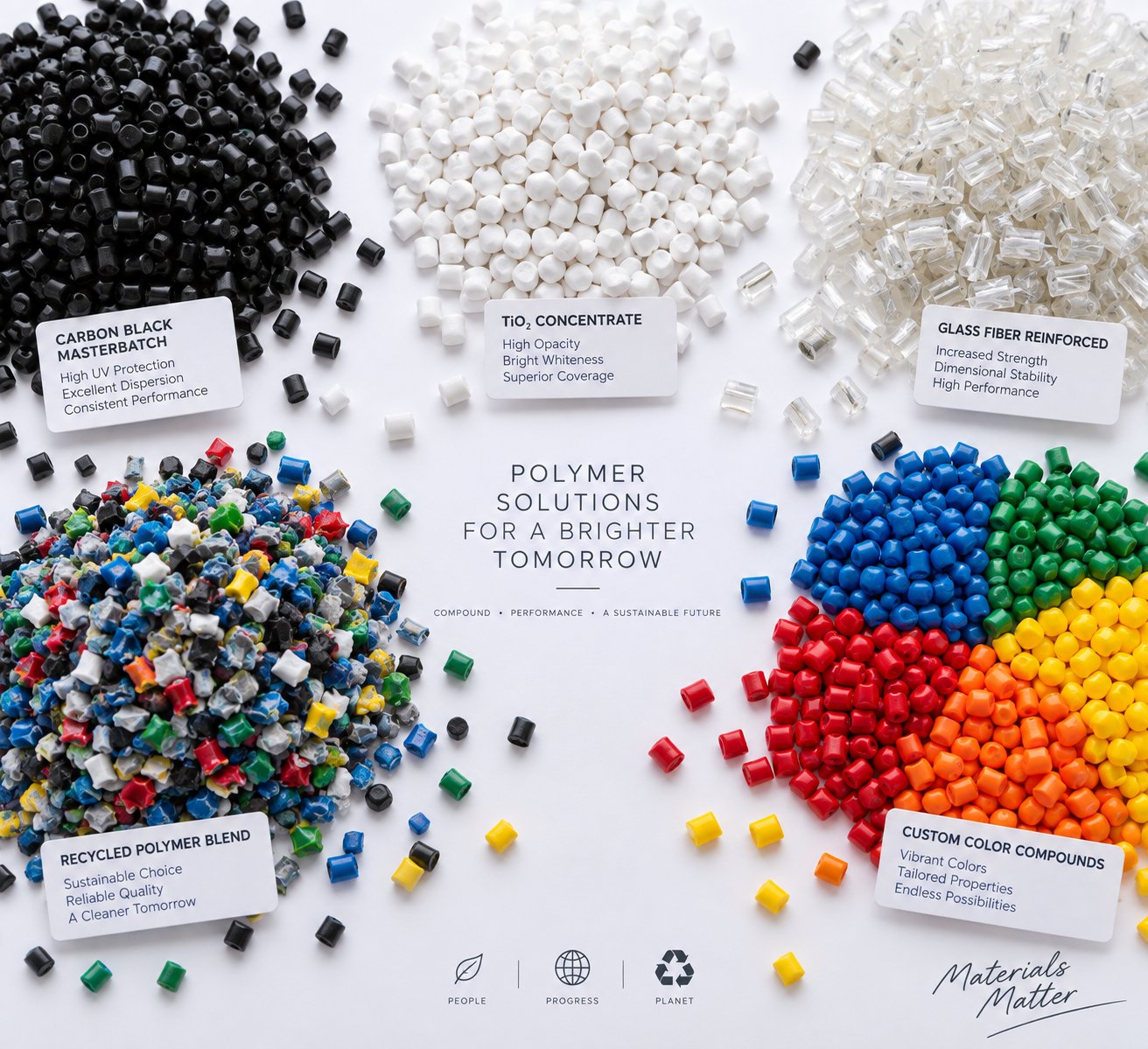
- Masterbatch, color, and additive concentrates — high pigment loading, carbon black, TiO2, and flame retardant concentrates
- Recycling, upcycling, and reactive extrusion — post-consumer reprocessing, chain extension, grafting, and controlled degradation
Each category demands something different from the extruder for polymer processing to succeed. Let's look at what makes the parallel twin screw the right tool for each job.
Polymer Blending and Engineering Plastics Compounding
Imagine blending polypropylene with polyamide—two polymers that, left to themselves, refuse to mix. PA/PP, PC/ABS, PPO/PS: these immiscible polymer blends require precise morphology control to achieve useful mechanical properties. The parallel twin screw extruder plastic compounding line handles this by letting engineers manipulate screw profile, barrel temperature, and screw speed independently. Adjusting the kneading intensity at specific barrel positions controls the size and distribution of dispersed-phase domains, while compatibilizers introduced through side feeders or liquid injection ports stabilize the blend interface. Research into reactive blending of recycled polypropylene with PA12 demonstrates how a maleic-anhydride-grafted compatibilizer, processed in a co-rotating twin screw extruder, forms diblock copolymers at the polymer interface—reducing domain size, improving interfacial adhesion, and restoring tensile strength to neat-polymer levels even with 50% recycled content.
Filled engineering compounds present a different challenge. Glass fiber reinforced polyamide or mineral-filled PBT formulations require the polymer extruder to disperse rigid additives uniformly without destroying them. Glass fibers lose mechanical value every time they break—so they're introduced via downstream side feeders, entering the melt after the polymer is already fully plasticized. From that point forward, gentle conveying elements and narrow-disc distributive mixing blocks spread fibers throughout the matrix while preserving their length. Mineral fillers like talc, wollastonite, and calcium carbonate demand strong dispersive kneading to break agglomerates down to primary particle size, but excessive shear raises melt temperature and can degrade the resin. Balancing these competing demands is exactly why modular screw design matters so much.
Masterbatch, Color, and Additive Concentrates
Walk into any masterbatch production facility and you'll find co-rotating twin screw plastic extruders at the center of every line. The reason is straightforward: high pigment loading and uniform color dispersion demand the kind of intensive kneading and narrow residence-time distribution that only intermeshing co-rotating screws deliver.
Carbon black masterbatch is one of the most demanding applications. At loadings of 30-40% or higher, carbon black's extremely fine primary particle size and strong interparticle attraction create stubborn agglomerates that resist breakup. Production experience confirms that poor dispersion leads to strand breakage during pelletizing, uneven die output, and visible defects in the final product. Solving these problems requires wide-disc kneading blocks generating high shear stress in the dispersive mixing zone, combined with optimized dispersant dosages, controlled hopper and feed-zone temperatures to prevent bridging, and careful screw speed management to balance dispersion quality against torque limits.
TiO2 white masterbatch follows a similar logic. Titanium dioxide agglomerates must be reduced to their primary particle size—typically around 200-300 nm—for maximum hiding power and color brightness. Flame retardant concentrates add another layer of complexity: many halogenated and non-halogenated flame retardant systems are thermally sensitive, so the screw profile must deliver sufficient mixing within a narrow temperature window to avoid decomposition and gas generation.
Across all masterbatch types, the narrow residence time distribution of the co-rotating twin screw prevents localized overheating that would discolor the carrier resin or degrade heat-sensitive additives. Quick color changes benefit from the self-wiping action—minimal residual material clings to screw surfaces, cutting purge times and scrap rates between production runs.
Recycling, Upcycling, and Reactive Extrusion
Plastic recycling has moved well beyond simple regrind reprocessing. Modern recycling operations use the twin screw extruder plastic compounding line to transform post-consumer and post-industrial waste streams into materials that approach—or even exceed—virgin polymer performance.
The challenge with recycled feedstocks is variability. Mixed polymer types, residual contaminants, moisture, and degraded molecular weight all work against consistent compound quality. The parallel twin screw extruder addresses each of these issues through its modular zone architecture: vacuum venting removes moisture and volatiles, kneading sections re-homogenize inconsistent melt, and side-feed ports introduce stabilizers, compatibilizers, and property-boosting additives at precisely the right barrel positions.
Upcycling research conducted by Thermo Fisher Scientific illustrates the potential clearly. By reactively blending reprocessed polypropylene with PA12 and a PP-g-MA compatibilizer in a co-rotating twin screw extruder, researchers achieved tensile strength equivalent to neat PA12—despite incorporating 50% recycled material. FTIR microscopy confirmed that the reactive blend achieved excellent chemical homogeneity, with a tight, Gaussian-like distribution of polymer components across the sample surface. Non-reactive blends, by contrast, showed wide compositional variability and distinct phase domains.
Beyond recycling, reactive extrusion opens an entire class of applications where the extruder functions as a continuous chemical reactor:
- Grafting — Maleic anhydride, silane, or acrylic acid groups are grafted onto polyolefin backbones to create functional compatibilizers and adhesion promoters.
- Chain extension — Epoxy-based or isocyanate-based chain extenders rebuild molecular weight in degraded PET or polycarbonate, restoring mechanical properties for demanding applications.
- Controlled degradation — Peroxide-initiated vis-breaking of polypropylene produces controlled-rheology grades with narrower molecular weight distribution and higher melt flow rates for fiber spinning or injection molding.
In each reactive application, the twin screw's ability to control residence time, mixing intensity, and temperature profile independently determines whether the chemical reaction proceeds to the target conversion—or falls short. The narrow residence time distribution ensures every polymer chain experiences similar reaction conditions, producing uniform graft levels or consistent molecular weight targets across the entire output.
These applications span an enormous range of materials, scales, and process complexities. A formulation that works perfectly on a 16 mm lab extruder still needs to perform at 500 kg/h on a production machine—and bridging that gap introduces a set of engineering challenges that deserve careful attention.
Scaling from Lab to Production in Parallel Twin Screw Compounding
A masterbatch formulation that produces flawless pellets on a 16 mm laboratory twin screw extruder can fall apart completely when transferred to a 92 mm production machine. Solid pellets discharge unmelted, pressure swings wildly, and phase separation destroys compound quality. Sound dramatic? It's exactly what happens when scale-up is treated as a simple exercise in multiplying throughput. Bridging the gap between a lab scale extruder and a full-production compounding line is one of the most technically demanding steps in bringing any formulation to market—and it's the step most commonly underestimated.
Lab-Scale and Pilot Twin Screw Extruders
Every new compound starts small. Laboratory extruder platforms with screw diameters ranging from roughly 11 mm to 27 mm are designed for exactly this purpose—they let process engineers develop formulations, screen materials, and prove out processing concepts without consuming large quantities of expensive raw materials.
Imagine you're developing a new glass-fiber-reinforced PA6 compound. At the lab scale, a single kilogram of resin and a handful of additives can yield enough data to evaluate dispersion quality, melt flow behavior, and mechanical performance. A lab extruder like an 11 mm platform can run at throughputs as low as 1 kg/h, meaning you can iterate through multiple screw configurations and temperature profiles in a single day using minimal material. That rapid iteration cycle is the real value proposition: you learn what works and what doesn't before committing to production-scale trials that burn through hundreds of kilograms per hour.
Beyond formulation screening, a laboratory twin screw extruder serves as a process feasibility tool. Can this filler loading be conveyed without bridging? Does this reactive system reach sufficient conversion within the available residence time? Will this pigment disperse to the required fineness rating? These questions are far cheaper to answer at the bench than on a production floor. Lab machines also let engineers test screw element configurations—trying different kneading block sequences, stagger angles, and reverse elements—before locking in a profile for a larger machine.
Pilot-scale extruders, typically in the 27 mm to 40 mm diameter range, occupy the middle ground. They process enough material for application testing and customer sampling—usually several kilograms per hour—while still keeping raw material costs manageable. More importantly, pilot trials reveal process behaviors that simply don't appear at the smallest scale, serving as an early warning system before the stakes get higher.
Scale-Up Principles from Lab to Production
Here's where things get interesting—and where many compounding projects stumble. Scale-up from a lab extruder to a production machine is emphatically not a matter of running the same screw speed and temperature profile at a proportionally higher feed rate. The physics change as diameter increases, and ignoring those changes leads to failed trials, wasted material, and delayed product launches.
The key scale-up principles center on preserving the process conditions that made the lab formulation successful:
- Geometric similarity — The lab and production extruders should share the same L/D ratio and the same outer-diameter-to-inner-diameter (OD/ID) ratio. A case study published in Plastics Technology used 26 mm, 40 mm, and 92 mm co-rotating extruders with identical L/D ratios of 44 and OD/ID ratios of 1.55, establishing the geometric foundation for meaningful comparison across scales.
- Matching specific mechanical energy (SME) — SME, expressed in kWh/kg, quantifies the mechanical energy transferred from the drive motor through the screws into the compound. It captures the combined effect of screw speed, torque, and throughput in a single number. When SME matches between scales, the compound experiences similar shear history—and that correlation protects product quality. In the Dow Chemical case study, the optimized SME on the 26 mm lab extruder was 0.083 kWh/kg. Directly transferring process conditions to the 40 mm pilot machine initially yielded an SME of only 0.055 kWh/kg—34% lower—resulting in poor mixing, phase separation, and material that could not even be pelletized. Only after adjusting screw design, temperature profile, and screw speed to bring SME back to 0.079 kWh/kg did the process stabilize.
- Preserving residence time distribution — Residence time is a critical process parameter for scale-up. As Thermo Fisher Scientific's compounding research emphasizes, matching average residence time between scales helps ensure that heat-sensitive formulations and reactive systems behave consistently. A higher throughput on a larger machine shortens residence time and narrows its distribution, so feed rate adjustments are often necessary to stay within the validated processing window.
- Accounting for heat transfer differences — This is the factor that catches engineers off guard most often. As barrel diameter increases, the volume of material grows by the cube of the diameter ratio, but the barrel surface area available for heating and cooling grows only by the square. The result? Larger extruders have proportionally less surface area per unit of material, reducing the effectiveness of barrel heating and cooling. A process that relied partly on barrel-wall heat transfer at the lab scale may need fundamentally more mechanical energy input—through screw design changes—at the production scale to achieve the same melt temperature.
The standard approach for estimating scale-up throughput uses established volumetric rules. When the process is power- or volume-limited, the target rate scales with the cube of the diameter ratio. When heat transfer through the barrel wall is the limiting factor, the rate scales with the square of the diameter ratio. The Plastics Technology study applied the cubic rule (power/volume-limited) and achieved a 3.64-fold rate increase from 26 mm to 40 mm and a 12.17-fold increase from 40 mm to 92 mm—but only after iterating on screw design and processing conditions at each scale to match SME.
Scale-up is not purely linear. Even with geometrically similar extruders, transferring a process across scales requires validation at intermediate sizes and iterative adjustment of screw design, temperature profile, and feed rate to match the specific energy and residence time established at the lab scale.
The lesson is clear: treat the lab-validated SME as your reference target, expect to adjust screw configuration and process parameters at every new scale, and use pilot-scale trials as your proving ground before committing to commercial production. Skipping the intermediate step is tempting—but the 92 mm case study, where initial scale-up produced unmelted pellets at an SME of just 0.026 kWh/kg (69% below the lab benchmark), shows just how costly that shortcut can be.
Screw element geometry and barrel section design must also maintain consistent quality across scales. If a kneading block's disc width or stagger angle varies even slightly between a pilot screw set and a production screw set, the mixing intensity changes—and the lab-validated formulation no longer translates. Dimensional precision in screw and barrel manufacturing isn't just a machining specification; it's a process-reliability requirement.
Selecting the Right Barrel and Screw Components for Production
Production-scale compounding places demands on barrel and screw metallurgy that lab-scale work rarely reveals. A 16 mm lab extruder might process a few hundred kilograms of a highly filled compound before showing measurable wear. A 92 mm production machine running the same formulation at 2,000 kg/h can abrade barrel liners and erode screw flight tips within weeks if the materials of construction aren't matched to the application.
Three metallurgical approaches dominate production barrel and screw construction, each suited to different compounding challenges:
- Nitrided steel — The entry-level option. Case hardening through nitriding creates a thin, hard surface layer on tool-steel substrates. Nitrided barrels and screws handle unfilled or lightly filled polymers well, but the hardened layer is shallow—once it wears through, the softer core material erodes rapidly. ENTEK's metallurgy analysis notes that industry use of nitrided tool steels has declined from roughly 70% to about 10% of their production mix as compounders have shifted to more demanding formulations.
- Bimetallic barrels with replaceable liners — A wear-resistant alloy liner is inserted into a barrel body made from a tougher, more ductile steel. When the liner wears out, it's replaced without discarding the barrel housing—which retains all the machined cooling passages, thermocouple wells, and bolt patterns. This approach significantly reduces long-term cost of ownership. As ENTEK reports, lined barrels have become the near-universal standard, offering a higher upfront investment that pays back quickly through refurbishment rather than full barrel replacement.
- Hot Isostatic Pressed (HIP) alloys and tungsten carbide coatings — For the most abrasive formulations—high glass-fiber loadings, ceramic-filled compounds, mineral concentrates—HIP alloys provide dramatically better wear resistance than nitrided or through-hardened steels. These powder-metallurgy alloys distribute hard carbide particles uniformly through the material, maintaining wear resistance even as the surface erodes. ENTEK's product mix has shifted to approximately 60% HIP alloys, reflecting the industry's move toward increasingly abrasive formulations. Tungsten carbide thermal-spray coatings offer another option for screw elements, creating an extremely hard surface layer that resists both abrasive and adhesive wear.
Corrosion resistance adds another dimension to metallurgy selection. Processing fluoropolymers, halogenated flame retardants, or acidic reactive systems requires high-chromium alloys or, in extreme cases, nickel-based superalloys like Inconel or Hastelloy. These exotic materials offer superior corrosion protection but sacrifice abrasive wear resistance and come at significantly higher cost—making them a targeted solution rather than a general-purpose choice.
One practical detail often overlooked: screw elements are typically manufactured from material that is equal to or slightly less wear-resistant than the barrel liner. The logic is economic. Screw geometries are complex but require less material removal during machining than barrels, making screws less expensive to replace. By allowing the screw to wear preferentially, you protect the more costly barrel and extend the interval between barrel refurbishments.
For production-scale compounding, working with a specialist barrel and screw supplier ensures that dimensional tolerances, metallurgical consistency, and surface finishes meet the tight standards that reliable extrusion demands. Even small deviations in bore diameter or liner hardness can alter the intermeshing clearance between screws, degrading self-wiping performance and introducing dead zones that compromise compound quality. NANHAIYA manufactures custom parallel twin screw barrels for compounding, recycling, pelletizing, granulation, and masterbatch production lines—matching barrel metallurgy and dimensional precision to each customer's specific materials and throughput requirements.
Getting the hardware right is foundational—but hardware alone doesn't guarantee results. The final step in building a reliable compounding operation is knowing how to evaluate machine specifications, optimize process parameters, and troubleshoot the issues that inevitably arise during production. That's where process engineering meets daily practice.
Selecting and Optimizing a Parallel Twin Screw Extruder for Compounding
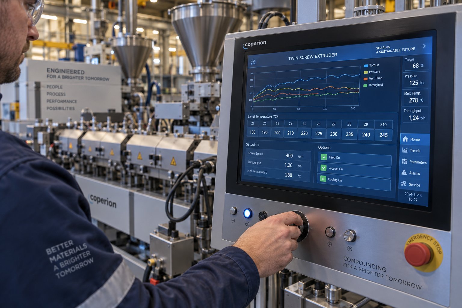
Hardware quality and screw metallurgy lay the groundwork—but standing in front of a twin screw extruder machine catalog or evaluating proposals from a twin-screw extruder manufacturer, you need to know which numbers actually matter. Specifications that look impressive on paper don't always translate to better compounds on the plant floor. Let's cut through the noise and focus on what drives real processing capability.
Key Specifications to Evaluate When Selecting an Extruder
When comparing compounding twin screw extruder options, resist the temptation to fixate on a single number like maximum throughput. Instead, evaluate how the entire specification set works together for your target formulations. Here's a practical checklist:
- Screw diameter — Determines your throughput ceiling. Production capacity scales approximately with the square of the diameter, so moving from a 50 mm to a 75 mm machine roughly doubles your rate potential.
- L/D ratio — Most compounding applications require an L/D between 32:1 and 48:1. Shorter ratios suit simple blending; longer ratios provide the extra barrel length needed for multi-stage venting, reactive extrusion, or high-filler-loading formulations where sequential side feeding demands additional processing zones.
- Specific torque density (Nm/cm³) — This tells you how much power the drive can deliver relative to the free volume available in the screw channels. Higher torque density means you can process high-viscosity melts—like fractional-melt HDPE or heavily filled compounds—without hitting torque-limited boundary conditions that cap your throughput.
- Maximum screw speed — Modern platforms reach 900 to 1,200 rpm. Higher speeds increase mixing intensity and throughput but also raise melt temperature through shear heating. The right speed depends on your material's thermal sensitivity.
- Free volume (OD/ID ratio) — The ratio of the outer screw diameter to the inner screw diameter indicates how much space is available for material in each channel. A higher OD/ID ratio—such as 1.66 versus 1.55—provides roughly 25-30% more volumetric capacity at the same screw diameter, directly increasing attainable throughput for volume-limited processes.
- Barrel configuration options — Count the available barrel positions and verify that open ports, side-feed barrels, vent barrels, and liquid injection barrels can be placed wherever your process demands. Flexibility here determines how many different formulations a single machine can handle.
- Drive and gearbox rating — The weakest link in torque transmission is the screw shaft. Verify the shaft spline design and NM rating—asymmetrically splined shafts represent the current state of the art for maximizing torque transfer.
Beyond specifications, consider the total cost of ownership. The twin screw extruder price on a purchase order is only the starting point—factor in barrel and screw replacement intervals, energy consumption per kilogram of compound, spare parts availability, and the cost of downtime when components wear out faster than expected. A lower-priced machine with shorter barrel life and limited element availability often costs more over five years than a premium platform with robust metallurgy and a deep spare-parts inventory.
Process Optimization and Troubleshooting Fundamentals
Even the best-specified twin screw compounding extruder needs tuning once it's running your formulation. Optimization boils down to balancing three interdependent variables—throughput, screw speed, and barrel temperature profile—to hit your target compound quality at the highest sustainable rate.
A useful framework comes from veteran compounding troubleshooter Adam Dreiblatt: classify every problem as either chronic or transient. Chronic problems—ones that appear every time a particular formulation runs—point to fundamental process design issues: wrong screw configuration, incorrect barrel layout, or operating conditions that simply don't match the material. Transient problems—ones that appear suddenly in a formulation that previously ran well—suggest raw material variation, mechanical failures, or environmental changes. Distinguishing between the two immediately narrows your investigation.
Here are the most common issues and their typical corrective actions:
| Problem | Likely Cause | Corrective Action |
|---|---|---|
| Poor filler or pigment dispersion | Insufficient shear in mixing zone | Add wider-disc kneading blocks, increase screw speed, or reduce throughput to increase residence time in mixing zones |
| Excessive melt temperature | Too much shear energy input | Reduce screw speed, remove kneading elements, increase barrel cooling, or raise throughput to reduce specific energy |
| Vent flow (melt exiting vent port) | Melt seal integrity compromised | Check that reverse elements upstream of the vent are creating a fully filled seal zone; verify that the vent zone isn't overfilled due to excessive feed rate |
| Surging (fluctuating torque or die pressure) | Inconsistent feeding | Verify gravimetric feeder calibration; check for powder bridging in hoppers; ensure side feeder screws are running in flooded condition to decouple upstream variability |
| Black specks or discoloration | Material hang-up or degradation | Inspect die adapter and screen changer for dead zones; verify screw elements are properly intermeshing; check barrel temperatures for hot spots from failed thermocouples or burned-out heaters |
One insight worth emphasizing: spatial patterns in defects—such as dark strands appearing only at specific die-hole positions—cannot be caused by the extruder itself, because the intermeshing screws thoroughly homogenize the melt before it reaches the die. If defects are localized to specific areas of the die plate, investigate the adapter, screen changer, or die body for dead zones, burned-out heaters, or flow imbalances. This single diagnostic principle can save hours of misdirected troubleshooting.
Train your operators to monitor trend curves rather than static numerical displays. As Dreiblatt recommends, graphical trend data over time reveals shifts, oscillations, and upset patterns that are invisible when watching individual numbers on a control screen. A gradual upward trend in torque over weeks, for instance, signals progressive screw or barrel wear—a problem you can plan for rather than react to after a catastrophic failure.
Building a Reliable Compounding Operation
Everything covered across this article—from figure-eight bore geometry and co-rotating screw mechanics to zone-by-zone processing, element-level screw design, scale-up methodology, and barrel metallurgy—converges on one practical outcome: building a compounding operation that produces consistent, high-quality compounds reliably, batch after batch.
The parallel twin screw extruder's dominance in compounding isn't accidental. It stems from three reinforcing strengths: modular design that adapts to virtually any formulation, intensive mixing capability that handles everything from nanoparticle dispersion to glass-fiber incorporation, and process flexibility that lets engineers optimize each zone independently without compromising others.
Long-term success, however, depends on decisions that extend well beyond the extruder itself. Matching the right screw configuration to your formulation's mixing demands. Selecting barrel metallurgy suited to the abrasiveness and corrosiveness of the materials you process. Designing a feeding strategy—gravimetric feeders, side stuffers, liquid injection—that delivers recipe accuracy at every inlet. Choosing downstream equipment—pelletizers, cooling systems, screening—that preserves the compound quality the extruder worked so hard to create.
Whether you're a process engineer evaluating twin screw extruder manufacturers for a new compounding line, a formulation scientist scaling a lab recipe to production, or a plant manager looking to squeeze more quality and throughput from existing equipment—the principles don't change. Understand the fundamentals deeply. Match your equipment and process to the specific demands of each application. Never stop optimizing.
The parallel twin screw extruder for compounding is not a black box. It's an engineering tool—powerful, flexible, and endlessly configurable—that rewards understanding with performance. The deeper your process knowledge, the more this machine delivers.
Frequently Asked Questions About Parallel Twin Screw Extruders for Compounding
1. What is the difference between a co-rotating and counter-rotating parallel twin screw extruder?
In a co-rotating extruder, both screws turn the same direction, creating self-wiping action and intense dispersive and distributive mixing with a narrow residence time distribution. Counter-rotating screws turn in opposite directions, producing a calendering effect with gentler shear and stronger positive-displacement pumping. Industry consensus holds that roughly 90% of compounding lines use co-rotating configurations because they deliver superior mixing versatility for filled compounds, polymer blends, and masterbatch. Counter-rotating machines excel in PVC dry-blend processing and reactive extrusion requiring low shear. The choice hinges on whether your application prioritizes mixing intensity or gentle, pressure-controlled conveying.
2. How do you scale up a twin screw compounding process from lab to production?
Successful scale-up requires maintaining geometric similarity (matching L/D and OD/ID ratios), matching specific mechanical energy input (kWh/kg), preserving residence time distribution, and accounting for reduced heat transfer efficiency at larger diameters. Simply multiplying throughput at the same screw speed and temperature profile frequently fails—case studies show SME mismatches of 30-70% that produce unmelted pellets and phase separation. Pilot-scale trials at intermediate diameters serve as a critical validation step. Barrel and screw component quality must also remain consistent across scales; dimensional deviations in kneading block geometry alter mixing intensity and invalidate lab-validated formulations. Suppliers like NANHAIYA manufacture custom parallel twin screw barrels with the dimensional precision needed for reliable scale-up across compounding, recycling, and masterbatch applications.
3. What screw elements are used in a parallel twin screw extruder for compounding?
Three fundamental element categories build every compounding screw profile. Conveying elements use helical flights to transport material, with pitch variations controlling fill level and residence time. Kneading blocks—the mixing workhorses—range from narrow-disc designs for distributive blending (color dispersion) to wide-disc designs for high-shear dispersive mixing (breaking filler agglomerates). Distributive mixing elements like toothed or gear-type designs split and recombine melt gently without excessive shear, preserving fiber length in reinforced compounds. Reverse-pitch elements create melt seals upstream of vacuum vent ports. Process engineers sequence these elements along splined shafts to build application-specific profiles, iterating until dispersion quality, melt temperature, and throughput reach target levels.
4. Why is a parallel twin screw extruder preferred over a single screw extruder for compounding?
Single screw extruders rely on drag flow and cannot transfer material between screws—the mechanism that gives twin screws their mixing superiority. Adding mixing sections to a single screw creates flow resistance, reduces output, and raises melt temperature. Parallel twin screw extruders offer fully modular screw and barrel construction, self-wiping intermeshing profiles that eliminate dead zones, and independent control over dispersive and distributive mixing intensity. They also provide scalable throughput from lab scale to over 20,000 kg/h, vacuum degassing capability, and side-feed ports for downstream filler or fiber addition. Single screw machines remain useful as forming devices for pre-compounded pellets, but they lack the mixing intensity and process flexibility that actual compounding demands.
5. What barrel materials are best for production-scale twin screw compounding extruders?
Production barrel metallurgy must match the abrasiveness and corrosiveness of the materials being processed. Nitrided steel provides entry-level hardness but wears quickly with filled compounds. Bimetallic barrels with replaceable wear-resistant liners have become the near-universal production standard—they allow liner replacement without discarding the barrel housing, reducing long-term ownership costs. Hot Isostatic Pressed (HIP) alloys distribute hard carbide particles uniformly and offer dramatically better abrasion resistance for high glass-fiber or mineral loadings. Corrosive applications like fluoropolymers or halogenated flame retardants require high-chromium or nickel-based alloys. NANHAIYA manufactures custom parallel twin screw barrels at https://www.nhyscrews.com/products/parallel-twin-screw-barrel, matching metallurgy and dimensional precision to specific compounding, recycling, and pelletizing requirements.
Written by
Nanhaiya Technical Team
Zhoushan Nanhaiya Plastic Machinery Co., Ltd.
The Nanhaiya technical team supports screw and barrel manufacturing projects through application review, technical communication, custom manufacturing coordination, and production and quality control.
Discuss Your Application
Related Articles
More insights on screw barrel technology and plastics processing.
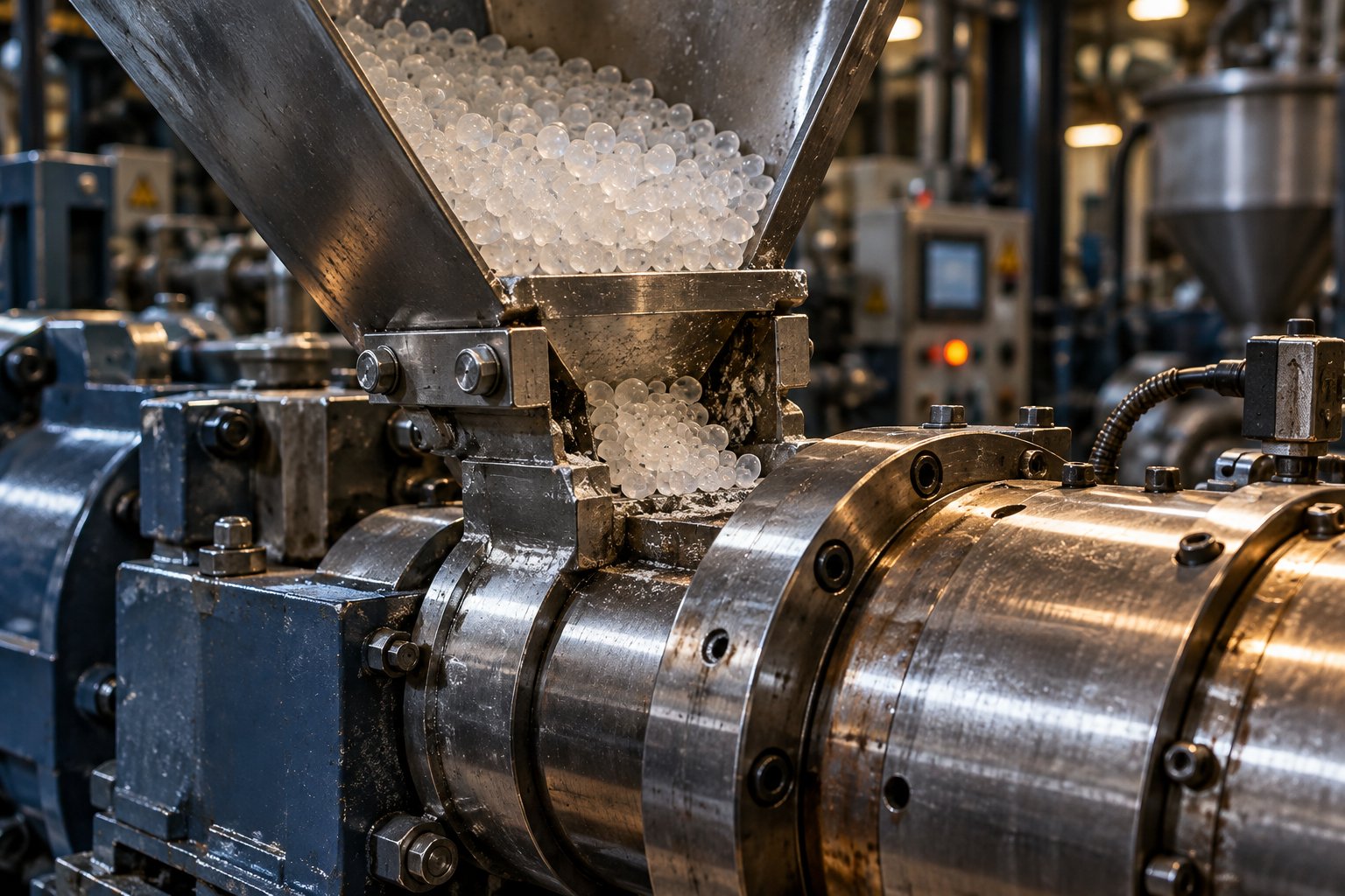
Your Extruder Feeding Instability Isn't Random — Here's Why
Oct 22, 2026
Extruder feeding instability causes surging output and scrap. Learn the 6 root causes, polymer-specific fixes, wear diagnostics, and preventive protocols.
Read Article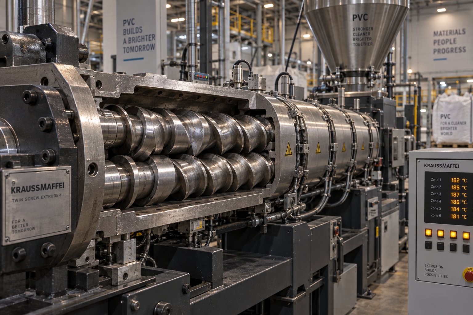
Twin Screw Extruder for PVC: The Setup Mistake Draining Profit
Oct 21, 2026
Learn how to match twin screw extruder configurations to PVC applications. Covers conical vs parallel, counter-rotating vs co-rotating, wear management, and troubleshooting.
Read Article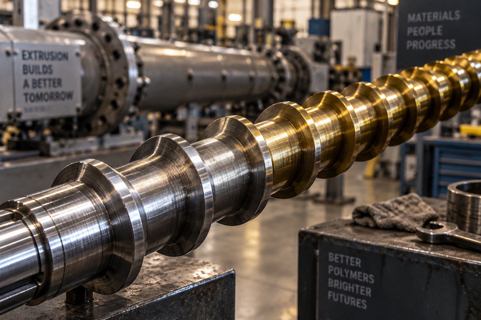
Plastic Extruder Screw Material Decoded: From Metallurgy to ROI
Oct 20, 2026
Learn how to select the right plastic extruder screw material — from carbon steel to bimetallic PM tool steels — matched to your resin, filler, and cost targets.
Read ArticleLooking for something else?
Search by material, symptom or product and jump straight to the relevant page.
These are navigation suggestions based on keyword matching — not a quotation, not a delivery commitment, and not a substitute for engineering review. Final specification is confirmed by our engineers against your drawings and processed material.
Need help with screw barrel selection?
Share your machine model, processed material and application. Our team can help with pricing and technical support.