

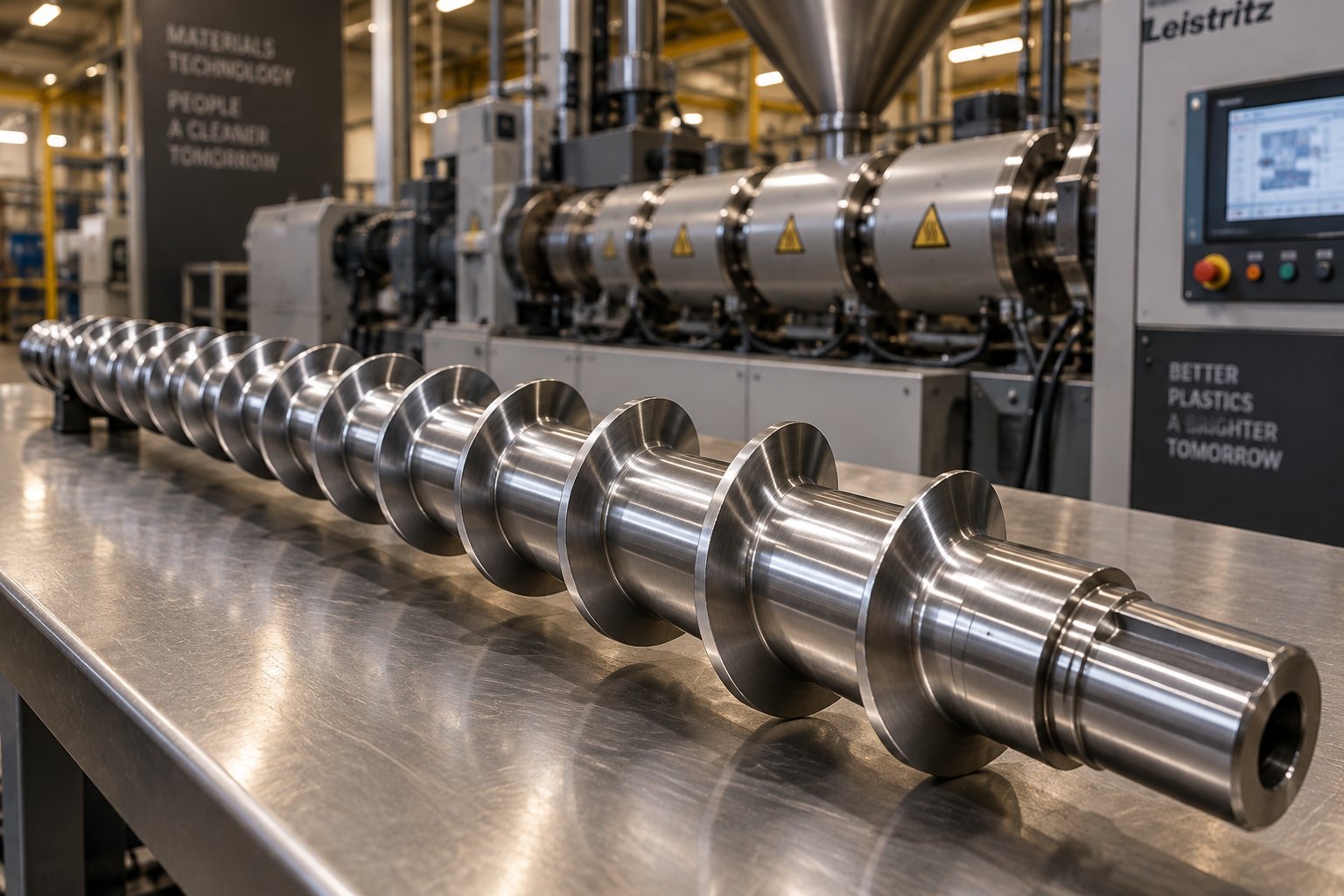
Understanding Screw Barrel Replacement and Why It Matters
Imagine your extruder slowly losing output, melt temperatures creeping upward for no apparent reason, and scrap rates climbing week after week. You tweak process settings, adjust barrel heater zones, and bump up screw speed — yet the problems persist. The real culprit? A worn screw barrel assembly that has quietly drifted past its useful service life.
Plastic extruder screw barrel replacement is one of the most consequential maintenance operations in any plastics processing facility. Yet it is also one of the most frequently delayed, misunderstood, and poorly planned. This guide is built for the people who actually do the work — maintenance engineers, process technicians, and plant managers — and it covers every stage of the replacement lifecycle, from recognizing the first symptoms of wear through diagnosis, decision-making, sourcing, installation, and post-replacement optimization.
What Screw Barrel Replacement Actually Involves
At its core, the screw barrel assembly consists of three interrelated components: the extruder screw itself (a helical mechanism responsible for conveying, compressing, melting, and metering resin), the barrel bore (the precision-machined cylinder that houses the screw), and the extruder feed barrel section where raw pellets first enter the system. Over thousands of operating hours, the clearance between the screw flight outside diameter and the barrel bore inside diameter gradually increases due to abrasive, adhesive, and corrosive wear mechanisms. Replacement means removing the worn screw, the barrel, or both — and installing components machined to original OEM specifications or, in many cases, improved specifications that better match the application.
The scope of replacement differs depending on your machine type. Single-screw extruders involve one helical screw and one barrel, making the replacement relatively straightforward in concept — though still demanding in execution. Twin-screw systems, whether co-rotating or counter-rotating, introduce additional complexity: two intermeshing screws, segmented screw elements, and tighter clearance tolerances that make wear assessment and replacement specification considerably more involved. Regardless of configuration, the underlying principle is the same — restoring the precise geometric relationship between the plastic extruder screw and its barrel to recover lost performance.
Why Replacement Timing Directly Impacts Your Bottom Line
Worn extruder screws and barrels don't just reduce output. They trigger a cascade of hidden losses that compound over time. As radial clearance between the screw flights and barrel wall increases, leakage flow rises — meaning resin slips backward over the flights rather than moving toward the die. The operator compensates by increasing RPM, which drives up energy consumption and generates excessive shear heating in the melt. Industry analysis from Plastics Technology confirms that this elevated melt temperature degrades physical properties in molded and extruded parts, especially with shear-sensitive resins like PVC and polycarbonate.
Higher melt temperatures also accelerate resin degradation, producing black specks, gels, and surface defects that inflate scrap rates. Root wear on the screw creates pockets where material hangs up and thermally degrades — a problem that worsens progressively as wear advances. In extreme cases, severely worn flight edges lose their structural integrity, chip away, and contaminate the extrudate or damage downstream components like screen packs and dies.
Running a worn screw barrel assembly past its service limit often costs more in hidden losses — wasted energy, elevated scrap, inconsistent quality, and unplanned downtime — than the replacement parts themselves.
This article walks you through a complete, practical framework: how to identify wear symptoms before they become emergencies, how to measure and quantify wear accurately, how resin selection affects replacement frequency, how to decide between replacing and refurbishing, how to specify and source the right components, and how to install and break in new parts for maximum longevity. Every section is built around the kind of actionable detail that keeps your extruder running — and your margins intact.
The first step in that framework? Learning to recognize exactly what a wearing screw and barrel look like from both the operator's chair and the process data screen.
Warning Signs Your Extruder Screw and Barrel Need Replacing
Screw and barrel wear rarely announces itself with a single dramatic failure. Instead, it creeps in through subtle shifts — a few extra amps on the motor drive, slightly wider dimensional tolerances on the extrudate, or a melt temperature reading that keeps climbing even though you haven't touched the heater setpoints. Each of these signals, taken individually, could point to half a dozen root causes. But when several appear simultaneously? That pattern almost always leads back to the extruder screw barrel.
Visual and Operational Symptoms of Worn Screw and Barrel Assemblies
You'll often notice the earliest clues during routine production, long before anyone pulls the screw for inspection. Here's what to watch for at the machine.
Declining output at constant RPM. This is the single most reliable early indicator. As flight OD wears down and barrel bore enlarges, the radial clearance increases and resin leaks backward over the flights instead of being conveyed toward the die. To maintain throughput, operators instinctively raise screw speed — which temporarily masks the problem but drives up energy input and shear heating. Research published in Plastics Technology demonstrates that for a 100-mm screw running PE at 150 kg/hr, progressive wear can force a rate reduction of up to 20 kg/hr — roughly a 13% capacity loss — before discharge temperatures become unmanageable.
Rising melt temperature without process changes. When clearance grows, the polymer film between the flight tip and barrel wall becomes thicker, reducing the barrel's heat-transfer coefficient. The result is higher discharge temperatures at the same screw speed. If you're seeing melt readings climb 5-10 degrees above historical baselines with no change to heater zones or line speed, worn extruder screws and barrels are a strong suspect.
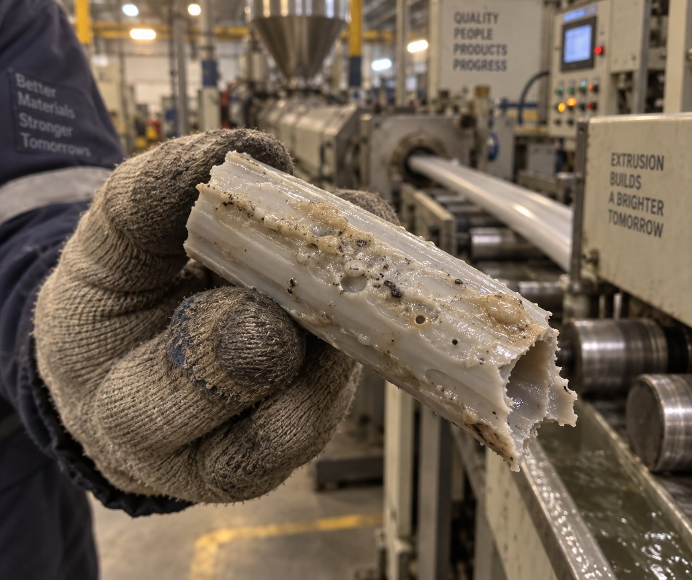
Visible extrudate quality degradation. Melt fracture, gels, unmelted particles, and surface roughness all point toward compromised melting and mixing performance. Abrasive wear on the flight tips reduces the screw's ability to generate the thin-film melting mechanism against the barrel wall, while adhesive wear on the barrel bore disrupts the heat-transfer surface that drives melting efficiency. Corrosive pitting — common in PVC processing — creates rough surface textures where resin hangs up and thermally degrades, producing black specks and discoloration.
Surging or pulsating output. A worn metering section loses its ability to deliver consistent volumetric flow. You'll see periodic fluctuations in die pressure, uneven wall thickness in blown film or pipe, and oscillating motor amperage. Surging can also originate from solids wedging at the end of the melting section, a condition that extrusion troubleshooting experts note creates momentary blockages and large side forces pushing the screw into the barrel wall — accelerating wear even further in a destructive feedback loop.
Increased motor amperage draw. As clearance increases, the screw must work harder to pressurize the melt against greater leakage flow. Motor amps trend upward at the same throughput, reflecting the higher energy demand imposed by a deteriorating screw-to-barrel fit.
Process Data Indicators That Signal Replacement Is Approaching
The symptoms above are observable on the shop floor. But the most powerful early-warning signals live in your process data — if you're tracking the right metrics.
Rising specific energy consumption (kWh/kg). Specific energy is perhaps the most sensitive wear indicator available. It normalizes power consumption against throughput, filtering out the noise of speed changes and rate adjustments. When specific energy starts trending upward over weeks or months with no material or process change to explain it, the screw barrel assembly is losing efficiency.
Widening product dimensional tolerances. Wall thickness variation in pipe, sheet gauge inconsistency, or profile dimensional drift all reflect a metering section that can no longer deliver stable, homogeneous melt flow. If your quality control data shows standard deviations growing even as operators tighten process setpoints, that's a telltale data fingerprint of internal wear.
Increased back pressure in screen packs. Degraded resin — caused by excessive residence time in worn screw root areas or poor melting performance — fouls screen packs faster. If you're changing screens more frequently without having changed resin lots or contamination levels, consider wear as a contributing factor.
Declining mixing or dispersion quality. Color streaks, additive agglomerates, and uneven filler distribution indicate that the screw's mixing sections have lost geometric precision. Worn barrier flights, for instance, allow unmelted solids to bypass the intended melting pathway.
To keep these indicators organized and actionable, use the following checklist as a quick diagnostic reference:
- Visual indicators: Extrudate surface defects (gels, melt fracture, unmelts), discoloration or black specks, visible scoring on pulled screw flights
- Operational indicators: Declining output at constant RPM, rising melt temperature, surging or pulsating flow, increased motor amperage
- Process data indicators: Rising specific energy (kWh/kg), increased screen pack change frequency, widening dimensional tolerances
- Product quality indicators: Poor color dispersion, inconsistent mechanical properties, higher reject or scrap rates
Here's the critical distinction that separates experienced troubleshooters from everyone else: a single symptom is ambiguous. Contaminated resin can cause gels. An incorrect temperature profile can raise melt temperature. A plugged screen pack can increase back pressure. But when you see three or four of these symptoms appearing together — declining specific rate, higher discharge temperature, worsening extrudate quality, and rising energy consumption — the overlap strongly points to extruder screw and barrel wear rather than a process setup issue. Contaminated resin doesn't raise motor amps. An incorrect temperature profile doesn't reduce specific rate. Only progressive clearance growth produces that particular constellation of symptoms simultaneously.
Recognizing these warning signs is essential, but it still leaves a critical question unanswered: exactly how much wear has actually occurred? Subjective observations get you in the diagnostic ballpark — precise measurements tell you whether you've reached the replacement threshold or still have operating margin left.
How to Measure and Inspect Screw and Barrel Wear Accurately
Symptoms get you suspicious. Measurements get you certainty. The difference between a well-timed plastic extruder screw barrel replacement and an expensive emergency shutdown often comes down to whether someone picked up a bore gauge and documented what they found — or simply kept running the machine until it forced the decision for them.
Every plastics processor should include routine inspection of plasticizing components in their maintenance program, as Adams Engineers emphasizes — and with good reason. Precise dimensional data transforms replacement from a reactive scramble into a planned, budgeted event. This section walks through exactly what to measure, how to measure it, and how to interpret the numbers you get.
Essential Measurements for Screw Flight and Barrel Bore Assessment
Three measurements define the health of any extrusion screw barrel assembly: screw flight outside diameter (OD), barrel bore inside diameter (ID), and the radial clearance between them. Each one tells a different part of the wear story, and you need all three to make a sound replacement decision.
Screw flight OD. This is where abrasive wear shows up most visibly. The flight tips — the outermost edges of the helical screw — grind against the barrel wall with every rotation, and over thousands of hours that contact progressively reduces flight diameter. To measure it accurately, remove the screw from the extruder barrel, clean off all residual resin while the screw is still warm using brass gauze (never steel brushes, which can scratch measurement surfaces), and let it cool to room temperature. Place the screw on a clean, flat work surface — ideally a granite inspection table where you can also roll it to check for bowing or straightness issues.
Use an outside micrometer or, for better repeatability, a parallel test bar spanning two adjacent flights to capture the true outer diameter. Experienced inspection teams recommend measuring flight OD at every other flight through the feed, transition, and metering sections. Don't just measure at a single clock position — rotate the screw and take readings at 0, 90, 180, and 270 degrees to detect uneven wear patterns that indicate screw deflection or misalignment. Record root diameter between every other flight as well, since root wear creates dead spots where resin hangs up and degrades.
Barrel bore ID. Compared with the screw, the extrusion barrel is relatively straightforward to measure — but the procedure still demands discipline. Use a dial bore gauge paired with an outside micrometer for calibration, or a telescoping gauge set for barrels where access depth is limited. Industry practitioners take readings every two to three inches down the entire barrel length. Frequent measurement intervals catch localized wear zones that wider spacing would miss — particularly in the transition zone, where polymer melting generates the highest pressures and the most aggressive metal-to-metal contact.
At each axial position, take readings at multiple clock positions (typically 0 and 90 degrees) to detect oval wear patterns. A barrel that measures round at the feed end but oval in the transition section is showing classic screw-deflection wear — valuable diagnostic information that influences whether you replace the barrel, the screw, or both.
Temperature matters. Metals expand when heated, and an extruder barrel at operating temperature has a measurably larger bore diameter than the same barrel at room temperature. Standard practice is to take formal inspection measurements at room temperature for repeatability and comparability across inspection intervals. If you need to assess clearance at operating conditions, apply the thermal expansion coefficient for your barrel steel — typically around 6.5 x 10⁻⁶ inches per inch per degree Fahrenheit for 4140 steel — but always document the temperature at which measurements were taken so future readings can be compared on an apples-to-apples basis.
Also inspect the feed hole area for cracks, washout spots, and bending, and visually assess the bore surface for scoring, pitting, or chemical etching. These qualitative observations supplement your dimensional data and often reveal corrosion-driven damage that dimensional measurements alone won't capture.
Interpreting Clearance Data and Setting Replacement Thresholds
You've collected your measurements. What do the numbers actually mean?
The critical value is diametral clearance — the difference between the barrel bore ID and the screw flight OD at any given axial position. On a new assembly, this clearance is tightly controlled by the OEM based on screw diameter. As both surfaces wear, the clearance grows: flight OD shrinks, barrel bore ID enlarges, and the gap between them widens in both directions simultaneously.
Santa Fe Machine Works publishes one of the most referenced clearance guideline charts in the industry, covering screw sizes from 1/2 inch through 10 inches (and metric equivalents from 25 mm to 140 mm). Their data establishes three clearance categories per screw size: new clearance, worn clearance (indicating components are approaching end of life), and maximum wear clearance (the point beyond which continued operation risks serious performance degradation or damage). For example, a 2-1/2 inch screw starts life with 0.007 to 0.010 inches of diametral clearance; a worn reading falls around 0.021 inches; and the maximum acceptable wear clearance is 0.030 inches. A 90 mm screw begins at 0.009 to 0.010 inches, reaches the worn threshold near 0.021 to 0.022 inches, and hits the replacement ceiling at 0.036 to 0.037 inches.
The general pattern across all sizes: replacement is typically triggered when clearance reaches roughly two to three times the original new specification. But these published values are guidelines, not universal rules. Your OEM documentation may specify different thresholds based on barrel metallurgy, screw design, and intended application. Always consult the machine manufacturer's recommendations first — and when those aren't available, the clearance growth trend over successive inspections becomes your most reliable decision tool.
To make your inspection data actionable, structure it in a standardized log. Here's a sample format you can adapt to your own machines:
| Measurement Location | Nominal Dimension | Measured Dimension | Calculated Diametral Clearance | Status |
|---|---|---|---|---|
| Feed zone - Position 1 (0 deg) | 2.500" | 2.504" | 0.012" | Acceptable |
| Feed zone - Position 1 (90 deg) | 2.500" | 2.505" | 0.013" | Acceptable |
| Transition zone - Position 5 (0 deg) | 2.500" | 2.518" | 0.026" | Monitor |
| Transition zone - Position 5 (90 deg) | 2.500" | 2.522" | 0.030" | Replace |
| Metering zone - Position 9 (0 deg) | 2.500" | 2.510" | 0.018" | Acceptable |
| Metering zone - Position 9 (90 deg) | 2.500" | 2.511" | 0.019" | Acceptable |
Notice how the sample log captures readings at multiple clock positions per axial location. That oval wear pattern in the transition zone — 0.026 inches at 0 degrees versus 0.030 inches at 90 degrees — reveals screw deflection wearing the barrel unevenly. This detail drives a smarter replacement decision than a single averaged number ever could.
Assess flight wear and bore wear independently. This point is easy to overlook but critical. If screw flight OD has worn down significantly while the barrel bore remains close to nominal, you may only need to replace the screw — a substantially lower cost. Conversely, if the barrel bore has enlarged but the screw flights still measure within tolerance, a new barrel liner or full barrel replacement is the priority. Only when both components exceed acceptable clearance — or when the combined clearance from simultaneous wear on both surfaces crosses the threshold — do you need to replace the complete assembly. Tracking each dimension separately in your inspection log makes this distinction visible at a glance.
Over time, these logged measurements create a wear profile that reveals how fast your specific machine, running your specific resins, consumes its plasticizing components. That wear rate data is the foundation for predicting your next replacement window — and as it turns out, the resin flowing through the barrel has an enormous influence on how quickly that window arrives.
How Different Resin Types Affect Wear Rate and Replacement Frequency
Not all resins treat your screw and barrel equally. A processor running unfilled LDPE on a single-screw line may go years between replacements, while a compounder pushing 40% glass-filled nylon through the same size machine could burn through an extrusion screw in a fraction of that time. The resin flowing through the barrel is, in many cases, the single largest variable determining how quickly wear accumulates — and understanding that relationship is essential for specifying the right replacement components rather than simply reordering what you had before.
Abrasive Resins and Glass-Filled Compounds
Glass-fiber-reinforced nylons, mineral-filled polyolefins, and talc- or mica-loaded engineering compounds are among the most punishing materials a plasticating unit will ever encounter. The mechanism is straightforward: hard, angular filler particles are compressed between the screw flight tips and the barrel wall with every rotation, grinding away metal on both surfaces simultaneously. Glycon Corp.'s Jeff Kuhman notes that some of the most aggressive fillers can reduce useful screw and barrel life by 50% or more compared to unfilled resins.
Abrasive wear manifests in several distinct patterns. Flight OD reduction is the most obvious — the outermost edges of the screw flights gradually lose material, widening the clearance gap and reducing conveying efficiency. Barrel bore enlargement occurs in parallel, particularly in the transition and metering zones where melt pressure forces filler particles against the bore surface under high load. Feed-section gouging is a subtler but equally damaging pattern: in the first several flights of the screw, pellets containing surface-exposed filler particles — especially mica and fiberglass — scour the unprotected root of the channel before the resin melts enough to form a lubricating film.
Extrusion screw design experts point out that this root wear typically begins around the third or fourth flight turn and extends into the early transition section, concentrated on the push side of the flight. Once the resin starts melting, molten polymer lubricates the interface between pellets and the screw root — but in the feed zone, that protective melt layer doesn't yet exist. The result is rapid, localized erosion that can undermine the screw's structural cross-section if not caught during periodic inspections.
Recycled materials deserve special attention here. Regrind and post-consumer recyclate frequently contain contaminants that virgin resin never would — metal fragments, sand, paper fibers, bits of label adhesive, and even stray fasteners that escaped magnetic separators. These foreign particles act as aggressive abrasives, and because their presence is inconsistent from lot to lot, the wear they cause can be unpredictable. Processors running high percentages of recycled feedstock should plan for significantly shorter inspection intervals and budget for more frequent replacement cycles.
Corrosive Resins Including PVC and Fluoropolymers
Corrosion-driven wear operates through an entirely different mechanism than abrasion — and it looks different under inspection. Where abrasive wear produces smooth, gradual dimensional loss, corrosion creates pitting, surface roughness, and localized chemical etching that degrades the barrel bore and screw surfaces in an uneven, cratered pattern.
PVC is the most widely processed corrosive resin. At elevated temperatures — particularly when the material experiences excessive residence time or localized overheating — PVC thermally degrades and releases hydrochloric acid (HCl). That acid attacks any exposed iron-based surface in the flow path. Industry sources confirm that corrosive wear aggressively targets components with a high iron matrix, which includes most standard carbon-steel and nitrided-steel screw extruders unless specifically protected with corrosion-resistant alloys or coatings.
Fluoropolymers — PTFE, FEP, PFA, and related materials — pose an even more severe chemical challenge. Processing these resins above their recommended temperature window liberates hydrofluoric acid (HF), one of the most aggressive acids encountered in industrial settings. HF attacks not only iron but also silicon-containing alloys, making it destructive to a broader range of barrel liner materials than HCl. Fluoropolymer processing demands specialized metallurgy from day one, and replacement components must be specified accordingly.
The insidious aspect of corrosive wear is that it often operates in tandem with abrasion. A PVC compounder adding calcium carbonate filler, for example, faces both chemical attack from HCl and mechanical erosion from the mineral particles. This combination produces accelerated, compounding wear that outpaces what either mechanism would cause alone — and it makes the choice of replacement materials especially critical.
How Resin Selection Should Drive Replacement Part Specification
Here's the point many processors miss: plastic extruder screw barrel replacement isn't just about restoring dimensions. It's about matching the metallurgy and surface treatments of the new components to the actual demands of the resin being processed. Ordering a standard nitrided steel screw to replace a worn one in a glass-filled nylon application guarantees you'll be placing the same order again in half the expected service life — or less.
The following table organizes common resin categories against the material and surface treatment considerations that should guide your replacement specification, along with the relative wear rate you can expect:
| Resin Category | Primary Wear Mechanism | Barrel Material Consideration | Screw Surface Treatment Consideration | Relative Wear Rate |
|---|---|---|---|---|
| Unfilled polyolefins (PE, PP) | Mild abrasion / adhesion | Standard nitrided steel (e.g., nitrided 4140) | Nitrided or chrome-plated flights | Low |
| Glass-filled engineering resins (PA, PBT, PET) | Severe abrasion | Bimetallic liner with tungsten carbide particles | Tungsten carbide hardfacing or encapsulation on flights and root | Severe |
| Mineral-filled polyolefins (talc, CaCO3, mica) | Moderate to high abrasion | Bimetallic liner (iron-boron or nickel-based alloy) | Stellite or tungsten carbide hardfacing on flights | Moderate to High |
| PVC (rigid and flexible) | Corrosion (HCl) + mild abrasion | Nickel-based corrosion-resistant bimetallic liner | Corrosion-resistant hardfacing; chrome plating on root | Moderate (corrosion-driven) |
| Fluoropolymers (PTFE, FEP, PFA) | Severe corrosion (HF) | High-nickel or Hastelloy-type alloy liner | Nickel-based corrosion-resistant coatings | High (corrosion-driven) |
| Recycled / contaminated materials | Unpredictable abrasion + foreign object damage | Bimetallic liner with tungsten carbide particles | Tungsten carbide hardfacing on flights; consider nitrided root | High to Severe |
A few patterns emerge from this table. Unfilled commodity resins are forgiving — standard metallurgy handles them well, and replacement intervals can be long. Glass-filled compounds sit at the opposite extreme, demanding the highest-performance wear protection available on both the screw and barrel. Corrosive resins like PVC and fluoropolymers require an entirely different material strategy, prioritizing chemical resistance over hardness. And recycled feedstocks, because of their unpredictable contaminant loads, need to be treated as a high-wear application regardless of the base polymer.
For twin screw barrel configurations used in compounding, the wear challenge is compounded further. The intermeshing geometry of co-rotating twin-screw systems creates additional metal-to-metal contact zones, and the segmented screw element design means that individual elements in high-wear positions — kneading blocks and mixing sections — may need replacement well before elements in conveying zones show significant deterioration. Xtrutech's guidelines for twin-screw extruders recommend monitoring wear based on production volume rather than elapsed time, since the level of abrasion depends on how much material has actually passed through the machine rather than how many hours it has been running.
The takeaway is clear: when you reach the point of ordering replacement components, the resin you're processing should be the first input into the specification conversation — not an afterthought. And that specification conversation extends well beyond metallurgy alone, into the full range of coatings, hardfacing alloys, and liner technologies that can dramatically extend the service life of your next set of components.
Replace, Refurbish, or Keep Running — A Decision Framework
You've measured the clearances, identified the wear pattern, and confirmed that your screw and barrel assembly is degrading. The diagnostic work is done. The harder question follows immediately: do you replace the components outright, refurbish what you have, or keep running until the next scheduled shutdown? Each option carries different cost implications, risk profiles, and performance outcomes — and the right answer depends on variables that no generic rule of thumb can capture. What you need is a structured way to evaluate the tradeoffs for your specific situation.
The True Cost of Running Worn Components
Delaying replacement feels like saving money. In reality, it usually means spending more — just in ways that don't show up on a single purchase order. The hidden costs of continued operation with worn components fall into several distinct categories, and each one compounds over time.
Energy waste. As radial clearance between the screw flights and barrel wall increases, the screw loses pumping efficiency. More resin leaks backward over the flights instead of moving toward the die, forcing operators to increase RPM to maintain throughput. That higher screw speed translates directly into higher motor amperage and increased specific energy consumption (kWh/kg). Plastics Technology analysis confirms that operators compensate for worn screw and barrel assemblies by running faster, which drives up energy input and generates excessive shear heating in the melt — a double penalty of wasted electricity and degraded melt quality.
Scrap and rework. Worn metering sections can't deliver consistent volumetric flow. The result is wider dimensional variation in finished products — wall thickness swings in pipe, gauge inconsistency in sheet, or weight variation in profiles. Parts that once ran comfortably within spec begin drifting toward tolerance limits, pushing reject rates upward. Degraded mixing and melting performance also produce gels, unmelts, and color streaks that send finished goods straight to the grind bin.
Unplanned downtime risk. This is the cost category most processors underestimate. A severely worn screw flight can lose structural integrity and chip, sending metal fragments through the die and potentially damaging downstream equipment. Root wear weakened to the point of fatigue cracking can cause catastrophic screw breakage mid-run. A scored barrel bore may require emergency re-boring — if the barrel is even salvageable. Unplanned shutdowns of this nature don't just cost repair dollars; they blow holes in production schedules, delay shipments, and damage customer relationships.
Safety hazards. Broken screw sections, molten resin blow-back through compromised seals, and the need for emergency disassembly of a machine at operating temperature all introduce serious personnel safety risks that planned maintenance avoids entirely.
Quantifying these costs for your own operation requires tracking your specific scrap rates, energy bills, and downtime history. But the directional truth is universal: the cumulative expense of running worn components almost always exceeds the cost of timely intervention. As one industry expert puts it, many processors "spend a fortune on the hidden costs of increased energy consumption and material waste" to avoid the perceived expense of a replacement — only to discover, when the screw is finally pulled, that it's no longer even salvageable.
Replace vs. Refurbish — When Each Option Makes Sense
Replacement isn't the only path forward, and it isn't always the best one. Refurbishment — restoring worn components to serviceable condition — can deliver like-new performance at a fraction of the cost and lead time when the conditions are right. Understanding what refurbishment actually involves helps you evaluate whether it's viable for your situation.
Screw refurbishment options include flight hardfacing (welding a wear-resistant alloy overlay onto the flight OD, then re-grinding to original tolerances), chrome plating on root diameters to restore surface finish and prevent material hang-up, and straightening for screws that have developed a slight bow from thermal cycling or deflection wear. Nan Yun Industrial's refurbishment guide details a typical screw rebuild process: PTA welding on the thread crest after a base repair, followed by precision grinding to OEM dimensions — a procedure they report can more than double the service life of a nitrided screw compared to its pre-refurbishment condition.
Barrel refurbishment options include re-boring and honing to restore roundness and straightness in barrels that have developed oval wear, nitriding after re-boring to restore surface hardness, and bore hard chrome plating for corrosion-damaged barrels that still have sufficient wall thickness. Experienced refurbishers use horizontal boring machines to correct inner diameter ovality first, restoring true roundness and straightness, then finish with vertical honing to achieve the required bore dimension and surface finish.
When is refurbishment viable? Three conditions must all be met:
- Wear is moderate — clearances have exceeded new tolerances but haven't reached the point where base metal integrity is compromised
- The base metallurgy is sound — no fatigue cracks, deep corrosive pitting, or heat-check damage that undermines the screw's structural core
- Dimensions can be restored within original OEM tolerances after material is added back through welding, plating, or boring
When is full replacement necessary? Any of these conditions pushes you past the refurbishment threshold:
- Wear exceeds refurbishment limits — flight width is too narrow to support a weld overlay, or the barrel wall is too thin to re-bore without breaching safe minimums
- Metallurgical damage is present — corrosion has penetrated deeply, heat checking has cracked the bore surface, or fatigue cracks are visible in the screw root
- You're upgrading to better-suited materials — switching from a nitrided barrel to a bimetallic liner for a glass-filled application, for example, requires a new barrel regardless of the old one's dimensional condition
Reputable screw manufacturers typically state that a screw can be rebuilt three to four times before the base material is exhausted. However, with high-quality welding practices and careful metallurgical management, experienced rebuilders have achieved six to eight rebuilds on some screws — extending the useful life of a single forging by years and saving substantial capital in the process.
The following table provides a structured comparison to help frame the decision:
| Decision Factor | Continue Running | Refurbish | Full Replacement |
|---|---|---|---|
| Applicable Wear Level | Minor — clearances still within acceptable range | Moderate — clearances exceed new spec but base metal is sound | Severe — clearances exceed refurbishment limits, or metallurgical damage present |
| Typical Relative Cost | No upfront part cost, but ongoing hidden costs (energy, scrap, risk) | 30-50% of new component cost (varies by scope of work) | Full component cost (screw, barrel, or both) |
| Expected Service Life Outcome | Continued degradation; accelerating wear rate | Restored to near-new clearance; service life comparable to original if metallurgy matches application | Full new service life; opportunity to upgrade metallurgy and design |
| Downtime Impact | None immediately, but high risk of unplanned emergency shutdown | Planned shutdown required; typically shorter lead time than new fabrication | Planned shutdown required; longer lead time for manufacturing, but can be pre-staged |
| Risk Profile | High — catastrophic failure, safety hazards, customer delivery disruption | Low — if wear assessment confirms refurbishment viability | Lowest — new components with full design life ahead |
| Best Use Case | Wear is within spec and confirmed by measurement; schedule next inspection | Budget is constrained, base metal is good, and current screw design is adequate for the application | Wear is beyond refurbishment limits, you're switching resins, or upgrading to better-suited materials |
One scenario worth addressing directly: purchasing a used twin screw extruder or a secondhand single-screw line — such as a Davis Standard extruder for sale on the used equipment market. Buying used machinery often means inheriting unknown wear history. The screw and barrel may look acceptable visually but could be well past their optimal clearance window. Before commissioning any used equipment, a full dimensional inspection using the measurement procedures described earlier in this article is non-negotiable. The cost of a replacement screw and barrel should be factored into the acquisition budget from the outset, not discovered as a surprise after startup.
Building the Business Case for Timely Action
The strongest justification for timely screw and barrel replacement isn't the cost of the parts — it's the total cost of ownership over the machine's operating life. Framing the decision this way shifts the conversation from "how much does a new screw cost" to "how much is this worn screw costing us every month we keep running it."
Build your business case around three categories of quantifiable impact:
- Energy savings: Calculate your current specific energy consumption (kWh/kg) and compare it to the baseline established when the screw and barrel were new or last replaced. The difference, multiplied by your annual throughput and your electricity rate, gives you the annual energy penalty of worn components.
- Scrap reduction: Track your scrap rate trend over the same period. Multiply the incremental scrap percentage by your annual production volume and your material cost per kilogram. This is real money being ground up and reprocessed — or worse, landfilled.
- Downtime risk avoidance: Estimate the cost of one unplanned shutdown: lost production hours multiplied by your fully loaded hourly machine rate, plus emergency repair costs, plus any customer penalties or expedited shipping charges to recover delivery schedules. Even a conservative probability estimate of catastrophic failure makes this number significant.
When the sum of these ongoing costs approaches or exceeds the cost of replacement or refurbishment, the financial case is clear — and it usually becomes clear well before most plants actually pull the trigger. The goal is to reach that decision point with your measurement data, not with a broken screw sitting on the shop floor.
With the decision made and the business case justified, the next challenge is equally consequential: specifying the right materials, coatings, and metallurgy for the replacement components so the new parts last longer than the ones they're replacing.
Metallurgy and Coatings for Replacement Screw Barrels
Specifying the correct dimensions for a replacement screw or barrel is only half the equation. The other half — and arguably the more consequential half for long-term performance — is choosing the right base metallurgy and surface treatments. Two identically dimensioned extruder barrels can deliver wildly different service lives depending on the alloys and coatings selected. A nitrided steel barrel running unfilled polyethylene might last for years. That same barrel processing 40% glass-filled nylon? You could be measuring replacement-level clearances within months.
This section breaks down the material options available for both barrels and screws, explains what each one is designed to resist, and gives you a structured framework for matching the right metallurgy to your application.
Base Metallurgy Options for Replacement Barrels
When ordering replacement extrusion barrels, you'll encounter three broad categories of construction, each offering a different balance of cost, durability, and application suitability.
Nitrided steel barrels. The most common and cost-effective option. Typically built from 4140 alloy steel, these barrels undergo a gas nitriding process that diffuses nitrogen into the surface layer, creating a hardened case. Industry sources report that nitriding produces a case depth of approximately 0.015 to 0.020 inches at a hardness around 60 Rc. For processors running unfilled polyolefins, polystyrene, or other non-abrasive resins, nitrided barrels deliver solid performance at an attractive price point. The limitation? That hard case is thin. Once abrasive fillers or corrosive degradation products wear through it, the softer base metal underneath erodes rapidly — "like a hot knife through butter," as one extrusion screw design expert describes it.
Bimetallic barrel linings. This is where serious wear protection begins. Bimetallic barrels feature a centrifugally cast liner — a wear-resistant alloy metallurgically bonded to the inside of the barrel's steel shell. The liner material varies by application:
- Iron-boron alloys — a workhorse liner for moderate abrasion from mineral fillers like talc and calcium carbonate
- Nickel-based alloys — the standard choice for corrosive environments, particularly PVC processing where hydrochloric acid attacks iron-based surfaces
- Tungsten carbide matrix composites — the highest tier of abrasion protection, featuring tungsten carbide particles suspended in the bimetallic base metal. SpecialChem's technical review notes that incorporating tungsten carbide into the liner can increase barrel life by four to five times compared to earlier-generation bimetallic liners
Bimetallic linings are essential for glass-filled and mineral-filled compounds, where standard nitriding simply can't survive the abrasion rates involved. They also apply to injection molding barrel replacements running highly filled engineering resins — the same metallurgical principles hold regardless of the machine type.
Fully lined barrels for extreme-wear applications. In the most demanding scenarios — high glass-fiber loading, recycled streams with metal contamination, or aggressive fluoropolymer processing — some manufacturers offer barrels with full-length liners extending through the feed throat. These eliminate the vulnerable unprotected zones that standard bimetallic barrels sometimes leave at the barrel entrance.
Screw Surface Treatments and Hardfacing Options
While barrel metallurgy protects the bore, the screw needs its own defense strategy — and different zones of the screw face different wear challenges. Flight tips endure abrasive contact with the barrel wall. Root surfaces take punishment from unmelted pellets carrying exposed filler particles. Shank and drive sections need corrosion resistance and dimensional stability. Here are the primary treatment options.
Stellite hardfacing on screw flights. Stellite alloys — cobalt-based materials containing chromium, tungsten, and carbon — are among the most widely used flight-tip hardfacing materials in plastics processing. The microstructure of Stellite 6, for example, consists primarily of alpha-cobalt and chromium-iron carbide phases, which provide both hardness and toughness. Stellite 6 typically achieves a hardness of 38-42 Rc — hard enough to resist moderate abrasion while remaining machinable during final grinding. It's a strong choice for mineral-filled compounds and general-purpose wear protection, though it falls short for severe glass-fiber abrasion.
Tungsten carbide thermal spray coatings. For the most aggressive abrasive applications, tungsten carbide coatings applied via High Velocity Oxy-Fuel (HVOF) or spray-weld-and-fuse processes deliver substantially higher wear resistance than Stellite alone. Full encapsulation methods machine the screw channel deeper than final geometry, then build up the root and flight sides with a combination of Stellite (for machinability) and tungsten carbide composites (for maximum abrasion resistance at the flight tip). This dual-layer approach protects the entire channel profile, not just the flight OD.
Chrome plating on screw root and shank areas. Hard chrome plating provides a smooth, corrosion-resistant surface that prevents resin hang-up in the root area and protects the shank from chemical attack. It's particularly valuable in PVC applications where hydrochloric acid targets exposed steel. However, newer technical guidelines note that chrome plating's limited adhesion and susceptibility to peeling have led to declining use in high-end equipment — nickel-based alternatives are increasingly preferred for critical corrosion-resistance applications.
Specialized corrosion-resistant coatings. For fluoropolymer processing and reactive extrusion environments, nickel-based alloy coatings and high-chromium overlays provide the chemical resistance that neither Stellite nor tungsten carbide can deliver on their own. These coatings prioritize forming a stable passivation layer over raw hardness, shielding the base metal from acid attack rather than resisting particle abrasion.
Matching Materials to Your Application
With all these options available, how do you choose? The answer always starts with the resin you're processing — but throughput rate and operating temperature profile also matter. Higher screw speeds increase the severity of metal-to-metal contact at the flight tip, accelerating abrasive wear. Elevated barrel temperatures can soften some hardfacing alloys, reducing their effective hardness. The following table maps each major material and coating option against its best-fit application:
| Material / Coating | Best Application Fit | Relative Cost | Expected Wear Life Improvement vs. Standard Nitrided | Recommended Resin Types |
|---|---|---|---|---|
| Nitrided 4140 steel (barrel or screw) | Non-abrasive, non-corrosive processing | Low | Baseline | Unfilled PE, PP, PS, ABS |
| Iron-boron bimetallic barrel liner | Moderate abrasion resistance | Moderate | 2-3x | Talc-filled, CaCO3-filled polyolefins |
| Tungsten carbide bimetallic barrel liner | Severe abrasion resistance | High | 4-5x | Glass-filled nylon, mineral-filled engineering resins, recycled materials |
| Nickel-based bimetallic barrel liner | Corrosion resistance | Moderate-High | 3-4x in corrosive environments | PVC, CPVC, fluoropolymers |
| Stellite 6 flight hardfacing | Moderate abrasion on flight tips | Moderate | 2-3x on flights | Mineral-filled compounds, general-purpose wear upgrade |
| Tungsten carbide HVOF / encapsulation | Severe abrasion on flights and root | High | 4-6x on flights | Glass-filled engineering resins, highly filled compounds |
| Hard chrome plating (root/shank) | Corrosion protection and release | Low-Moderate | Corrosion-dependent | PVC, commodity resins where resin hang-up is a concern |
| Nickel-based alloy coating (full screw) | Severe corrosion resistance | High | Corrosion-dependent | Fluoropolymers, reactive extrusion, halogenated compounds |
To simplify the selection process, use this quick-reference checklist when specifying replacement components:
- Identify the primary wear mechanism: Is it abrasion (hard particles grinding metal), corrosion (chemical attack from degradation byproducts), or adhesion (resin sticking and tearing at the surface)?
- Match barrel liner to the dominant threat: Tungsten carbide composites for abrasion, nickel-based alloys for corrosion, standard nitrided steel only for non-aggressive resins
- Match screw hardfacing to the zone under attack: Flight tips need abrasion resistance (Stellite or tungsten carbide), root areas need protection from unmelted pellets carrying filler (nitriding, encapsulation, or J-groove welding), and shank areas need corrosion resistance (chrome or nickel-based coatings)
- Factor in throughput rate: Higher screw RPM increases flight-tip wear severity — lean toward harder coatings when running at or near maximum speed
- Consider operating temperature: Some hardfacing alloys lose effective hardness above certain temperatures — verify that your coating choice maintains performance at your barrel setpoint range
- Don't mix mismatched pairs: A tungsten carbide hardfaced screw running inside a standard nitrided barrel will wear through the barrel faster than the screw — both components should be specified as a system
That last point deserves emphasis. Specifying the correct metallurgy during the replacement ordering process is every bit as important as getting the dimensional accuracy right. A perfectly machined screw built from the wrong alloy for your application will lose clearance just as fast as the worn-out component it replaced — and you'll be right back where you started, only with a fresh purchase order to show for it.
Knowing what materials to specify is one thing. Communicating those specifications accurately to a supplier — and verifying that what arrives matches what you ordered — is an entirely separate skill set that many processors overlook until it costs them.
How to Source and Specify Replacement Screw Barrels
Getting the metallurgy right is a critical step. But even the perfect material selection falls apart if the specifications you hand to your supplier are incomplete, ambiguous, or — worse — based on worn dimensions rather than original design intent. Ordering replacement injection molding screws and barrels or extrusion components is a precision communication exercise, and the gap between what you think you ordered and what actually arrives can be measured in thousandths of an inch and thousands of dollars.
This section covers exactly what information to prepare before contacting a supplier, how to evaluate manufacturing partners, and what to verify the moment a crate hits your receiving dock.
Critical Specifications to Communicate When Ordering
Think of your specification package as the blueprint your supplier will use to machine every surface, select every alloy, and grind every flight. Missing a single detail can result in components that look correct but don't perform — or worse, don't fit. Here's the complete checklist of information your supplier needs to quote and manufacture accurately:
- Machine make and model: A Davis Standard extruder, a JSW injection molder, or a Coperion twin-screw compounder each has unique barrel-to-gearbox interfaces, flange configurations, and feed throat geometries. Providing the exact machine identification eliminates ambiguity about these critical mating dimensions.
- Screw diameter and L/D ratio: These two values define the fundamental geometry. A 90 mm, 30:1 L/D screw is a completely different component from a 90 mm, 24:1 — even though they share a diameter.
- Flight geometry: Pitch (distance between flight turns), channel depth in feed, transition, and metering zones, number of flights (single-flight vs. double-flight designs), and flight width at the tip.
- Barrel bore diameter and overall length: Specify nominal bore ID, not a measurement taken from the worn barrel. Include the total barrel length from flange face to flange face.
- Compression ratio: The ratio of feed channel depth to metering channel depth. This value drives melting performance and must match the resin being processed.
- Material and coating requirements: Base alloy (e.g., 4140, 38CrMoAl, or tool steel), nitriding specification, bimetallic liner type, and any hardfacing or chrome plating — all informed by the metallurgy decisions covered in the previous section.
- Custom features: Mixing sections (Maddock, pineapple, or distributive), barrier flights, vent ports, grooved feed sections, or non-standard shank configurations.
- Dimensional tolerances and surface finish: Specify required surface roughness (Ra 0.4 is a common standard for barrel bores), screw straightness tolerance (0.015 mm is a representative benchmark), and any critical-to-function dimensions with their acceptable ranges.
One common mistake deserves a specific warning: sending a worn screw to the supplier as a "reference sample" without clearly flagging that it is worn. If the supplier measures the sample and machines the replacement to match those dimensions, you'll receive a brand-new screw built to worn specifications — undersized flights, incorrect channel depths, and clearances that are already degraded from day one. Always provide original OEM drawings or specify nominal dimensions. If original documentation isn't available, state clearly which dimensions on the sample are worn so the manufacturer can reverse-engineer the correct geometry.
For processors running Davis-Standard extruder lines or other US extruders where original documentation may have been lost after decades of service, a reputable supplier can often cross-reference machine model numbers against their database of previously manufactured components — but only if you provide accurate machine identification upfront.
Evaluating Suppliers and Verifying Part Quality
A detailed specification package is only as good as the manufacturer executing it. Not all screw and barrel suppliers operate at the same level of capability, and evaluating them before placing an order saves far more grief than discovering quality problems after installation.
Manufacturing capabilities. Look for suppliers with in-house CNC turning and milling, heat treatment (nitriding furnaces, through-hardening ovens), centrifugal casting equipment for bimetallic liners, and precision grinding. Outsourcing critical processes like hardfacing or heat treatment introduces additional quality variables and extends lead times. A vertically integrated manufacturer who controls the process from raw billet through final inspection offers more consistent results — and a single point of accountability when something doesn't meet spec.
Material certifications and traceability. Request material test certificates (mill certs) for the base alloy and any liner or hardfacing materials. These documents trace the metal back to its source heat and confirm chemical composition, mechanical properties, and processing history. Procurement specialists emphasize that management system certifications like ISO 9001 confirm a supplier's process discipline but do not by themselves guarantee that every material grade or geometry is optimized for a specific application. Treat certifications as a qualification filter, then verify performance through specification data and first-article inspection.
Quality inspection reports. A credible supplier provides dimensional inspection reports showing actual measured values against drawing tolerances — not just a pass/fail stamp. Look for hardness test results (both surface and core), nitrided case depth verification, surface roughness measurements, and straightness data. Detailed parameter checks should cover nitrided hardness (typically HV850-HV1000), case depth (0.45-0.7 mm range for standard nitrided components), nitrided brittleness rating (less than Grade 2), and chromium plating hardness and depth where applicable. These are not abstract numbers — they directly predict how long your replacement components will last in service.
Responsiveness to custom requirements. Plastic extruder screw barrel replacement is rarely a catalog purchase. Your application probably requires specific compression ratios, custom mixing geometries, or non-standard materials. A supplier who pushes back on customization or quotes excessive lead times for anything beyond their standard lineup may not have the engineering depth to execute your specification reliably.
Lead times. Realistic manufacturing timelines vary significantly based on component size and complexity. For reference, documented lead times for nitrided single screw and barrel assemblies range from 40-50 days for diameters up to 90 mm, 50-60 days for 90-180 mm, and 60-70 days for 180-250 mm. Bimetallic configurations and special alloy requirements can extend these windows further. Build lead time awareness into your preventive maintenance planning so replacement orders go out well before the screw hits its clearance limit — not the day after it breaks.
Factory-direct sourcing has become an increasingly viable strategy for processors looking to reduce both cost and communication friction. Rather than working through distributors or trading companies who relay specifications through intermediaries — each handoff introducing potential for error — direct engagement with the manufacturing facility allows your engineering team to discuss tolerances, material options, and custom features with the people who will actually machine the parts.
Factory-direct sourcing eliminates intermediary markups and enables direct communication of custom specifications with the manufacturing team — reducing both cost and the risk of specification errors introduced through multi-layer supply chains.
One example of this model is NANHAIYA, a factory-direct manufacturer offering custom and replacement screw barrels for both extrusion and injection molding applications. Their product navigation covers barrel bodies, liners, screw elements, and shafts — allowing maintenance teams to specify components across the full range of plasticizing assemblies without sourcing each element from a different vendor. For plants managing multiple machine types — a mix of single-screw extruders, twin-screw compounders, and injection molding presses — consolidating screw barrel procurement through a single manufacturing source simplifies both the ordering process and quality verification.
What to Check When Replacement Parts Arrive
The order has shipped and a crate is sitting on your receiving dock. Before signing off and scheduling installation, invest the time in a thorough incoming inspection. Catching a dimensional error or material shortfall now costs you a phone call. Catching it after the screw is installed and running costs you a second shutdown.
- Dimensional verification: Measure screw flight OD, root diameter, channel depths, and overall length against the purchase order specifications. Measure barrel bore ID at multiple axial positions and clock angles, just as you would during a wear inspection. Compare every reading to the drawing tolerances — not to "close enough."
- Hardness spot-checks: Use a portable hardness tester to verify surface hardness on flight tips, root surfaces, and barrel bore. Readings should align with the supplier's inspection report and the specified material treatment.
- Surface finish inspection: Run a fingernail or a profilometer across the barrel bore and screw root. Machining marks, roughness beyond the specified Ra value, or visible grinding chatter are grounds for rejection or rework.
- Fit-check in the barrel: Before connecting anything to the drive, slide the new screw into the barrel and verify free rotation by hand. It should turn smoothly with no binding, tight spots, or audible scraping. Check the shank-to-gearbox coupling interface for dimensional accuracy and proper keyway alignment.
- Visual inspection for shipping damage: Look for nicks on flight edges, bending from improper crating, or corrosion from inadequate preservation during transit. Even minor flight-edge damage creates a stress riser that accelerates wear in service.
This incoming inspection step might feel tedious, especially when production is waiting. But consider the alternative: installing a screw with an out-of-spec flight OD or a barrel with a bore diameter that's already at the high end of tolerance means you've effectively shortened the component's service life before it processes a single pellet. The fifteen minutes spent measuring on the dock can save months of premature wear down the road.
With verified replacement parts in hand and specifications confirmed, the focus shifts to the most physically demanding phase of the entire process — safely removing the worn components, installing the new ones, and breaking them in properly to maximize their operational lifespan.
Safe Removal, Installation, and Break-In Procedures for Barrel Extruder Components
You've measured the wear, justified the business case, specified the metallurgy, sourced the parts, and verified them on the receiving dock. Everything up to this point has been planning. What comes next is physical, unforgiving work — and the phase where the most serious injuries, equipment damage, and costly mistakes occur. A screw extruder full of 400-degree polymer, weighing hundreds of pounds, and bolted to a gearbox spinning at high torque is not a forgiving environment for improvisation.
Yet surprisingly few resources cover the safety protocols and procedural details specific to pulling and reinstalling plasticizing components. This section closes that gap with a structured approach to removal, installation, alignment, and the often-overlooked break-in period that determines how long your new components will actually last.
Safety Protocols for Screw and Barrel Removal
Every screw pull starts with the same question: is everything that can move, heat, or pressurize fully locked out? The consequences of skipping this step range from serious burns to fatal crush injuries. Here's how to approach it systematically.
Lockout/tagout (LOTO). Before touching anything, lock out and tag out the extruder drive motor, the barrel heater circuits, and any auxiliary systems connected to the barrel — cooling water, vacuum venting, and pneumatic slide gates. If the machine has a hydraulic screw pusher or injection unit, lock that out too. Each energy source gets its own lock. Each person working on the machine applies their own lock. No exceptions, no shortcuts.
Thermal hazards. This is the risk most often underestimated. An extruder barrel retains dangerous surface temperatures for hours after heaters are de-energized. Even after the controller reads ambient, localized hot spots can persist inside the barrel bore — particularly in thick-walled sections and near the feed throat where thermal mass is highest. Never assume a barrel is safe to touch because the heaters are off. Use a contact pyrometer or infrared thermometer to verify surface temperatures before placing bare hands, slings, or rigging straps against any barrel section.
Heavy-lift rigging. A single-screw extruder screw in the 4.5-inch class can weigh well over 200 pounds. Larger screws — 6-inch, 8-inch, 10-inch — require overhead cranes, chain hoists, or forklifts equipped with proper fixtures. Barrel sections on twin screw and barrel systems can be even heavier when accounting for heater bands, thermocouples, and insulation jackets still attached. Plan your rigging path before you unbolt anything, and confirm that lifting equipment is rated for the load.
Screw extraction procedure. The recommended approach, consistent with guidance from Plastics Technology, follows a clear sequence. First, run the extruder at slow screw speed with the hopper empty or the slide gate closed until resin stops flowing from the die. While the barrel is still at processing temperature, remove the transfer line and die to expose the discharge end. Then push the screw out using a hydraulic pushing jack or a threaded push rod — never a forklift, a come-along, or any improvised mechanical advantage device. Push the screw out approximately three to four diameters at a time, inspecting and cleaning each exposed section with brass tools, copper gauze, and stearic acid before advancing the next segment. Never stand in the screw extraction path. A screw under hydraulic pressure that suddenly breaks free becomes a projectile weighing hundreds of pounds.
Use the following checklist to ensure nothing is missed across each phase of the removal process:
- Pre-removal: Complete LOTO on drive motor, heater circuits, hydraulics, and auxiliaries. Verify barrel temperature with contact measurement. Stage rigging equipment, cleaning tools (brass scrapers, copper gauze, stearic acid), and screw support stands. Remove hopper and close or remove feed throat slide gate. Clear the work area of tripping hazards and establish an exclusion zone behind the screw extraction path.
- During removal: Run barrel to processing temperature for heat soak (facilitates screw extraction). Purge remaining resin at low RPM. Remove die and transfer line while barrel is hot. Push screw out incrementally using hydraulic jack — never impact force. Inspect and clean each section as it exits. Use only brass or copper cleaning tools — steel tools can damage base metal and chrome plating. Never use a torch to remove resin — localized heating can alter the grain structure of the steel, weaken the screw, and potentially cause bends.
- Post-removal: Support the extracted screw on padded V-blocks to prevent bending under its own weight. Clean the barrel bore with a brass wire brush wrapped in copper gauze, rotated with an electric drill while the barrel is still warm. Perform all dimensional inspections on the removed screw and barrel bore. Document measurements in the wear log for trend tracking.
Step-by-Step Installation and Alignment Best Practices
Installation is not removal in reverse. It introduces its own set of risks — and the single most important variable is one that many maintenance teams overlook: alignment between the barrel bore and the gearbox drive quill.
Barrel installation. Start by verifying bore cleanliness. Even a small fragment of degraded resin left in the bore can score a brand-new screw on the first rotation. Run the brass-and-gauze brush through the full bore length one final time and shine a light down the barrel to visually confirm a clean surface. If heater bands were removed during barrel replacement, reinstall them with verified wattage and zone placement before mounting the barrel — it's far easier to install heater bands on a barrel sitting on stands than one bolted to the machine frame.
Alignment is critical, and the stakes scale with barrel length. Davis-Standard's engineering team emphasizes that the barrel must be aligned to the drive quill of the gearbox — not simply leveled. Leveling only measures the vertical plane and tells you nothing about whether the barrel centerline actually coincides with the drive quill centerline. The correct procedure uses an optical or laser alignment scope inserted into the drive quill to establish a fixed centerline, then adjusts the barrel supports and feed throat mounting faces to bring the barrel into alignment with that reference.
Barrel support systems deserve attention during reinstallation. The barrel must be able to expand freely as it heats — steel expands at approximately 0.000006 inches per inch per degree Fahrenheit, meaning a 4.5-inch, 36:1 L/D barrel at 450 degrees F grows roughly 0.320 inches longer than its cold dimension. If the support system prevents straight-line thermal expansion, the barrel will bow — creating uneven screw-to-barrel contact that accelerates wear on the brand-new components you just installed. Verify that supports use non-corrosive contact materials (brass is standard) to prevent freezing, and that they are rigid enough to maintain position without tipping as the barrel thermally cycles.
Torque barrel flange bolts in a star pattern to manufacturer specifications — uneven torque creates stress concentrations that can distort the flange face and compromise the seal with the feed throat or adjacent barrel section. On twin screw and barrel systems with segmented barrels, this becomes even more critical: each barrel segment interface must mate squarely under uniform bolt loading to maintain bore continuity.
Screw installation. Inspect the new screw one final time for shipping damage — nicks on flight edges, surface scratches, or any deformation from rough handling in transit. Even minor flight-edge nicks create stress risers that accelerate local wear.
Here's a key practice that experienced technicians follow and that Plastics Technology experts strongly recommend: always install a new or rebuilt screw into a cold, clean barrel for its first insertion. The barrel bore is at its smallest diameter when cold. If the screw slides in freely under these conditions, you've confirmed that the flight OD is within specification and that no bends or fabrication errors are present. Installing a cold screw into a hot barrel — where thermal expansion has enlarged the bore — can mask a dimensional defect. When the system reaches equilibrium and the screw expands to operating diameter, an oversized flight or a subtle bend can cause the screw to bind inside the barrel. Extracting a bound screw typically damages both components.
Once a screw has been confirmed defect-free through a cold-barrel insertion, subsequent installations can be done with the screw cold and the barrel hot. But that first installation into a cold barrel is non-negotiable.
Verify free rotation by turning the screw by hand through at least two full revolutions. Listen for scraping or feel for tight spots. If the screw won't turn freely, do not force it — remove and investigate. Check the drive shank engagement with the gearbox quill. If the shank doesn't seat smoothly, apply machinist's bluing to the quill interior, reinsert the screw, and look for transfer marks indicating high points on the spline or keyway. Remove small amounts of metal at the contact points and iterate until the engagement is smooth. Never use a forklift or excessive force to push a screw into a drive quill — one documented case involved fork-truck impact that caused drive quill damage that wasn't discovered until years later when the screw had to be replaced again.
Finally, verify feed throat alignment with the screw channel and confirm thrust bearing condition. A worn thrust bearing will allow axial play that affects metering zone pressure stability and can cause the screw to contact the barrel end cap — a problem that no amount of careful screw and barrel specification can overcome.
Break-In Procedures to Maximize New Component Longevity
Your new screw and barrel are installed, aligned, and cleared for startup. The temptation is to fire up the heaters, bring the line to full production speed, and start recovering the output you lost during the changeover. Resist that impulse. New components require a controlled break-in period, and skipping it can measurably shorten their service life.
Why does break-in matter? Freshly machined metal surfaces — even precision-ground ones — have microscopic asperities (high points) on the flight tips and barrel bore. During initial operation, these asperities undergo controlled wear-in: they flatten and conform to each other, creating a smooth, consistent contact surface. If you immediately subject new components to full speed and an abrasive resin, those asperities experience aggressive point-loading that can cause localized galling, micro-welding, or surface tearing. The result is premature surface damage that establishes wear patterns far more destructive than the gradual, uniform wear that properly broken-in surfaces experience.
Follow these practices to protect your investment during the critical first hours of operation:
- Start at reduced RPM. Bring the screw up to approximately 25-50% of normal operating speed during initial operation. This limits flight-tip contact pressure and allows asperities to wear in gradually rather than being torn off under full load.
- Use a non-abrasive resin for the first hours. If your production schedule allows it, run an unfilled polyolefin — LDPE or natural PP — during break-in. These soft, non-abrasive materials allow surfaces to condition without the added stress of glass fiber or mineral filler grinding against fresh metal. Even a few hours of gentle running with non-abrasive resin makes a measurable difference in long-term surface quality.
- Gradually increase to full speed. Over a period of several hours — longer for larger-diameter barrel extruder systems — ramp screw speed upward in increments. If you need to transition to your production resin (including abrasive compounds), make that material change after the initial low-speed conditioning period, then continue the gradual speed ramp with the production material.
- Monitor motor amps and melt temperature closely. During break-in, these two parameters are your primary feedback channels. Motor amps should trend stable or slightly decreasing as surfaces condition. Any sudden spike in amperage suggests binding, misalignment, or a dimensional issue that needs immediate investigation — shut down and inspect before damage propagates. Melt temperature should stabilize within your expected range; persistent overheating at low RPM indicates a clearance or alignment problem.
- Document baseline measurements. This step is the bridge between installation and long-term maintenance. Once break-in is complete and the machine is running at full production parameters, record your baseline data: motor amps at rated RPM, melt temperature, specific energy consumption (kWh/kg), output rate, and melt pressure. Predictive maintenance specialists recommend running a new baseline for two to four weeks after a known maintenance event like a screw replacement — this dataset becomes the reference point for all future deviation analysis. When specific energy starts trending upward or output at rated RPM starts declining months down the road, you'll have a clean starting number to compare against.
That baseline documentation isn't just good practice — it's the foundation of a preventive maintenance program that transforms your next plastic extruder screw barrel replacement from a reactive emergency into a planned, budgeted event. And building that program is exactly where the final piece of this lifecycle framework comes together.
Building a Preventive Maintenance Schedule to Extend Barrel Life
Baseline data collected during break-in is only valuable if it feeds into a living maintenance program — one that captures measurements at regular intervals, tracks trends over time, and flags replacement thresholds before they become emergencies. Without that structure, even the best break-in documentation ends up in a filing cabinet, forgotten until the next unplanned shutdown forces a screw pull at 2 AM.
A well-designed preventive maintenance schedule transforms every plastic extruder screw barrel replacement from a reactive crisis into a planned, budgeted event. It also extends the time between replacements by catching correctable problems — misalignment, cooling system blockages, feed throat wear — before they accelerate screw and barrel degradation. Whether you're maintaining a single-screw plastic extruder, a twin-screw compounder, or an injection screw assembly, the framework is the same. Only the intervals change.
Recommended Inspection Intervals and Measurement Checkpoints
Imagine stacking three layers of inspection on top of each other, each one deeper and less frequent than the last. That tiered structure mirrors how wear actually progresses: slowly and invisibly at first, then accelerating as clearances widen and performance degrades. Your inspection program should mirror that progression.
Tier 1: Routine visual and operational checks. These happen weekly or at every material changeover — whichever comes first. They don't require pulling the screw or stopping production. You're looking at the process from the operator's chair: motor amperage trends, melt temperature stability, extrudate surface quality, and any signs of surging. During purging operations, inspect the purge material for discoloration, black specks, or unmelted particles that signal degrading melt quality. These checks take minutes, cost nothing, and catch early-stage problems that dimensional measurements wouldn't reveal for weeks.
Tier 2: Periodic dimensional measurements. This is where you pull the screw, measure flight OD at multiple axial and clock positions, gauge the barrel bore, and calculate diametral clearance — exactly the procedure detailed earlier in this article. How often? Industry maintenance guidelines recommend measuring screw flight diameter and barrel bore every 500 to 1,000 operating hours and tracking clearance growth over time. That range is a starting point, not a rule. Adjust it based on the resin abrasiveness data covered earlier: a screw plastic extruder running 40% glass-filled nylon needs inspection far more frequently than one processing unfilled LDPE.
Tier 3: Comprehensive shutdown assessments. During major planned shutdowns — annual turnarounds, equipment overhauls, or whenever the screw is pulled for any reason — perform a full inspection of every component in the plasticizing assembly. This includes not just screw and barrel measurements, but also thrust bearing play, gearbox oil analysis, feed throat condition, barrel alignment verification, and heater band resistance checks. These deep inspections feed your wear trend data and validate whether your Tier 2 interval is appropriate or needs adjustment.
The following table provides a sample preventive maintenance schedule you can adapt to your own equipment and operating conditions:
| Inspection Type | Frequency | Measurements / Checks | Tools Required | Action Triggers |
|---|---|---|---|---|
| Visual and operational check | Weekly or at material changeover | Motor amps, melt temperature, extrudate quality, purge material condition, surging observation | Amp clamp, IR thermometer, visual inspection | Amps trending above baseline; melt temp rising without process change; visible quality defects in extrudate |
| Periodic dimensional measurement | Every 500-1,000 operating hours (adjust for resin abrasiveness) | Screw flight OD, barrel bore ID, diametral clearance at feed/transition/metering zones, screw root diameter, bore ovality | Outside micrometer, dial bore gauge, telescoping gauges, straightedge | Clearance exceeding monitor threshold; oval wear pattern developing; clearance growth rate accelerating |
| Comprehensive shutdown assessment | Annually or at major planned shutdown | All Tier 2 measurements plus: thrust bearing axial play, barrel alignment check, gearbox oil sample, heater band resistance, feed throat bore inspection, cooling channel flow verification | Full gauge set, laser/optical alignment scope, oil sampling kit, megohmmeter, flow meter | Clearance approaching replacement threshold; alignment drift detected; bearing play exceeding OEM spec; heater resistance out of range |
A critical nuance: the 500 to 1,000 hour range for Tier 2 inspections is calibrated for moderate-wear applications. If your operation runs highly abrasive compounds — glass-filled engineering resins, recycled materials with contaminant loads, or heavily mineral-filled polyolefins — tighten that interval to the lower end or even shorter. Conversely, processors running clean, unfilled commodity resins can safely extend toward the upper bound. The wear rate data from your first few inspection cycles will tell you exactly where your specific application falls on that spectrum. Let the data guide the interval, not a calendar.
Documentation Practices That Predict Replacement Timing
Here's where the real payoff happens. Individual measurements are snapshots. A series of measurements plotted over time is a wear curve — and a wear curve is a prediction tool.
Maintain a dedicated screw and barrel wear log for each machine. Every time you perform a Tier 2 or Tier 3 inspection, record the date, cumulative operating hours since last replacement, and all dimensional readings using the standardized log format introduced in the measurement section of this article. Over successive inspections, you'll see clearance values gradually increasing — slowly at first, then accelerating as the nitrided case or bimetallic liner wears through and softer base metal becomes exposed.
Plot these clearance values against operating hours. The resulting curve reveals two critical pieces of information:
- Current wear rate: The slope of the curve tells you how many thousandths of an inch of clearance you're gaining per thousand hours of operation. A steeper slope means faster wear — possibly indicating a material mismatch, alignment problem, or a change in resin that's accelerating degradation.
- Projected replacement date: Extrapolate the curve forward to your replacement clearance threshold (defined by OEM specifications or the industry guideline charts referenced earlier). The point where the projected curve crosses that threshold is your predicted replacement window — typically weeks or months in the future, giving you ample time to budget, order components, and schedule the shutdown.
This approach works equally well for injection molding screws as it does for extrusion components. The wear mechanisms are the same — abrasion, corrosion, adhesion — and the clearance thresholds follow the same principles. An injection screw processing glass-filled PBT builds a wear curve just as predictably as an extrusion screw running the same compound. The only difference is the inspection access procedure and the machine-specific measurement points.
Beyond dimensional data, document your operational baselines at each inspection interval: motor amps at rated RPM, melt temperature, specific energy (kWh/kg), and output rate. Predictive maintenance specialists note that after two or three screw replacements with full data, you can predict screw replacement timing within weeks — turning what was once a $20,000 or more emergency repair into a planned maintenance event. These operational metrics often shift before dimensional measurements reach alarm levels, giving you an even earlier warning signal when something is changing inside the barrel.
The discipline here isn't complicated. It's consistency. A measurement taken once is a data point. The same measurement taken every 750 hours for three years is a trend line that tells you exactly when to act — and exactly how much service life your metallurgy and coating choices are actually delivering in your specific application.
A proactive measurement and documentation program is the single most effective way to minimize both replacement costs and unplanned downtime — turning screw and barrel management from a reactive emergency into a predictable line item on your maintenance budget.
When your wear trend data indicates that replacement is approaching — clearances climbing toward the threshold, specific energy trending upward, output declining at rated RPM — having a reliable supply partner already identified accelerates the entire process. Lead times for precision-machined screw and barrel assemblies can stretch 40 to 70 days depending on size and metallurgy. If you're scrambling to find a supplier after the screw is already pulled, those weeks of lead time become weeks of lost production.
Build your supplier relationship before you need it. Share your machine specifications, preferred metallurgy, and typical order scope in advance so quoting and manufacturing can begin the moment your measurement data says it's time. For processors seeking a factory-direct option, NANHAIYA offers a manufacturing-direct model where maintenance teams communicate custom specifications — barrel bodies, liners, screw elements, shafts — directly to the production source for both extrusion and injection molding screw barrel needs. That direct line to the factory floor eliminates the specification relay errors that plague multi-tier supply chains and keeps lead times as short as the manufacturing process allows.
Ultimately, every section of this guide connects back to a single operating philosophy: measure early, document consistently, decide based on data, specify precisely, install carefully, and repeat. Plastic extruder screw barrel replacement doesn't have to be a guessing game. With the right inspection framework, the right documentation habits, and the right supply partnerships in place, it becomes one of the most predictable and manageable maintenance activities in your entire plant — protecting your output, your margins, and your equipment for every operating hour ahead.
Frequently Asked Questions About Plastic Extruder Screw Barrel Replacement
1. How do I know when my extruder screw and barrel need replacing?
Multiple simultaneous symptoms strongly indicate replacement is due rather than a simple process adjustment. Watch for declining output at constant RPM, rising melt temperature without process changes, visible extrudate defects such as gels or unmelted particles, surging output, and increasing motor amperage. On the data side, track rising specific energy consumption (kWh/kg), widening dimensional tolerances in finished products, and more frequent screen pack changes. When three or four of these indicators appear together, the cause is almost certainly progressive clearance growth between the screw flights and barrel bore — a condition no process tweak can resolve. Routine dimensional measurement using bore gauges and outside micrometers confirms whether clearances have reached the OEM-defined replacement threshold.
2. What is the acceptable clearance between an extruder screw and barrel before replacement is needed?
New diametral clearance between the screw flight OD and barrel bore ID is set by the OEM based on screw diameter. As a general industry guideline, replacement is typically triggered when that clearance reaches roughly two to three times the original specification. For example, a 2.5-inch screw may start with 0.007 to 0.010 inches of clearance, reach a worn threshold around 0.021 inches, and hit maximum acceptable wear at approximately 0.030 inches. However, these values vary by machine and application. Always consult your OEM documentation first. If exact thresholds are unavailable, tracking clearance growth over successive inspections at multiple axial positions and clock angles provides the most reliable trend data for predicting when replacement is necessary.
3. Should I replace or refurbish a worn extruder screw and barrel?
Refurbishment is viable when wear is moderate, the base metal is structurally sound with no fatigue cracks or deep corrosive pitting, and dimensions can be restored to OEM tolerances through welding overlay, re-grinding, re-boring, or chrome plating. A quality rebuild typically costs 30-50% of new component pricing and can restore near-new performance. Full replacement becomes necessary when wear exceeds refurbishment limits, when metallurgical damage is present, or when you need to upgrade to better-suited materials — for instance, switching from a nitrided barrel to a bimetallic liner for glass-filled applications. Reputable manufacturers report that a screw can often be rebuilt three to four times before the base material is exhausted, making refurbishment a cost-effective strategy when conditions allow.
4. How does the type of resin affect extruder screw and barrel wear rate?
Resin selection is often the single largest variable determining wear rate and replacement frequency. Unfilled commodity polyolefins like PE and PP cause minimal wear, allowing long service intervals with standard nitrided steel components. Glass-fiber-reinforced engineering resins such as nylon and PBT cause severe abrasive wear, potentially cutting component life by 50% or more and demanding tungsten carbide bimetallic liners and hardfaced screw flights. PVC generates hydrochloric acid at elevated temperatures, causing corrosive pitting that requires nickel-based alloy protection. Recycled and contaminated feedstocks introduce unpredictable abrasives — metal fragments, sand, and paper — requiring aggressive wear protection and shorter inspection intervals. Matching replacement part metallurgy to your specific resin is essential for maximizing service life.
5. Where can I source custom replacement screw barrels for extrusion and injection molding machines?
When sourcing replacement screw barrels, evaluate suppliers based on in-house manufacturing capabilities (CNC machining, heat treatment, centrifugal casting for bimetallic liners), material certifications with full traceability, dimensional inspection reports, and responsiveness to custom requirements. Factory-direct sourcing from manufacturers like NANHAIYA (nhyscrews.com/products) eliminates intermediary markups and allows your engineering team to communicate tolerances, metallurgy preferences, and custom geometries directly with the production floor. Their product range covers barrel bodies, liners, screw elements, and shafts for both extrusion and injection molding platforms. When placing orders, always provide original OEM drawings or clearly specify nominal dimensions — never send a worn screw as a reference without flagging which dimensions have degraded.
Written by
Nanhaiya Technical Team
Zhoushan Nanhaiya Plastic Machinery Co., Ltd.
The Nanhaiya technical team supports screw and barrel manufacturing projects through application review, technical communication, custom manufacturing coordination, and production and quality control.
Discuss Your Application
Related Articles
More insights on screw barrel technology and plastics processing.

What Nobody Tells You About Screw Barrel For Plastic Machine Design
Oct 10, 2026
Learn how screw barrel for plastic machine design affects melt quality, throughput, and wear life. Covers geometry, resin matching, troubleshooting, and sourcing.
Read Article
Single Screw Extruder for Sheet: Stop Guessing, Start Specifying
Oct 9, 2026
Learn how to specify a single screw extruder for sheet production. Covers screw geometry, resin-specific processing, troubleshooting, and maintenance best practices.
Read Article
PE Pipe Extruder Machine: What Datasheets Won't Tell You
Oct 9, 2026
Learn how a PE pipe extruder machine works, key specs explained, material grade selection, maintenance tips, and buyer guidance beyond the datasheet.
Read ArticleLooking for something else?
Search by material, symptom or product and jump straight to the relevant page.
These are navigation suggestions based on keyword matching — not a quotation, not a delivery commitment, and not a substitute for engineering review. Final specification is confirmed by our engineers against your drawings and processed material.
Need help with screw barrel selection?
Share your machine model, processed material and application. Our team can help with pricing and technical support.