


What a PE Pipe Extruder Machine Does and Why It Matters
Imagine a single machine that can take a pile of tiny plastic pellets and transform them into a continuous, precision-engineered pipe stretching hundreds of meters long. That is exactly what sits at the core of every polyethylene pipe manufacturing facility. Yet most equipment datasheets reduce this complex system to a handful of numbers - screw diameter, motor power, output rate - without ever explaining what those numbers actually mean for your production or your bottom line.
A PE pipe extruder machine is a continuous processing system that melts polyethylene resin pellets under controlled heat and pressure, then forces the molten polymer through an annular die to form a seamless pipe profile. It serves as the central unit in a complete extrusion line that includes feeding, melting, shaping, cooling, and cutting stages to produce finished pipes for water supply, gas distribution, drainage, and telecom ducting.
What Is a PE Pipe Extruder Machine
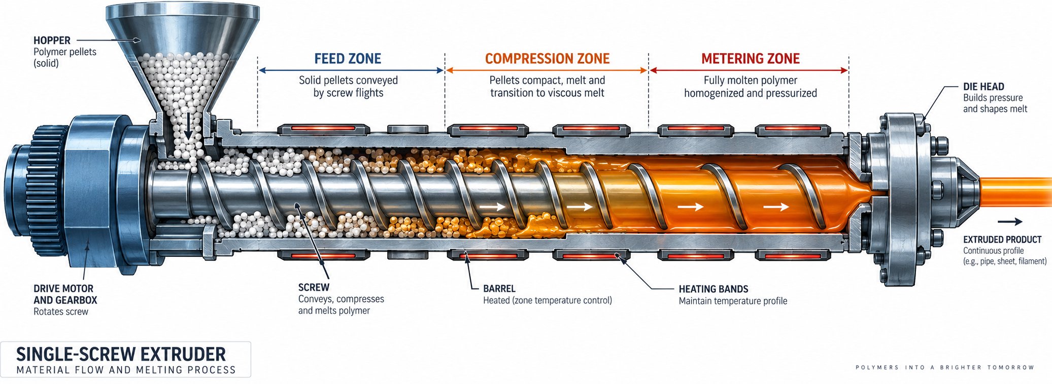
At its simplest, a pipe extruder machine converts raw polyethylene granules into finished pipe through a process called continuous extrusion. Pellets enter a hopper, drop into a heated barrel where a rotating screw melts and pressurizes them, and then the molten polymer is pushed through a specially shaped die head that forms the hollow pipe profile. The result is a seamless tube that gets cooled, sized to exact dimensions, and cut to length - all in one uninterrupted flow. This plastic pipe extrusion machine runs around the clock in many facilities, producing everything from small 16 mm irrigation tubing to massive 1600 mm diameter water mains.
Why PE Pipe Extrusion Matters Across Industries
Polyethylene has become the dominant material for both pressure and non-pressure piping systems, and the reasons are practical. PE pipes resist corrosion, handle chemical exposure without degrading, flex under ground movement without cracking, and deliver a service life exceeding 50 years. These properties make the extrusion of pipes from PE resin essential across multiple sectors - municipal water supply, natural gas distribution, sewage and drainage networks, agricultural irrigation, and telecom ducting.
The global demand behind these machines is substantial. The PE pipe market is projected to grow from USD 19.75 billion in 2026 to USD 27.87 billion by 2035, expanding at a 3.9% CAGR. Global production volume already exceeded 17.5 million metric tons, with HDPE pipes alone accounting for roughly 68% of total volume. Water supply applications dominate at over 40% of total demand, while more than 55% of new water pipelines installed globally now use HDPE. Behind every one of those pipes is an extruder machine that made it possible.
What This Resource Covers
This guide goes well beyond the typical datasheet. You'll find a step-by-step breakdown of how the extrusion process actually works, a detailed tour of every component in a complete PE pipe extrusion line, and plain-language explanations of the technical specifications manufacturers list but rarely clarify. We also cover how different PE material grades affect machine selection, compare single-screw and twin-screw configurations, walk through a structured buyer's guide, outline maintenance and troubleshooting best practices, and explore the energy-saving and Industry 4.0 technologies reshaping modern pipe production.
The goal is straightforward: give you the practical knowledge that equipment brochures leave out, so you can make better decisions - whether you are specifying a new line, optimizing an existing one, or evaluating a machine purchase for the first time. And that understanding starts with knowing exactly what happens inside the barrel from the moment those pellets drop in.
How a PE Pipe Extruder Machine Works Step by Step
Most manufacturers publish a simple flow diagram and call it a day. That barely scratches the surface. Every stage of the pipe extrusion process involves specific physics - friction, heat transfer, pressure gradients, crystallization kinetics - and understanding them is what separates a well-run line from one that constantly fights quality issues. Here is what actually happens from the moment polyethylene pellets leave the storage silo to the second a finished pipe rolls off the line.
- Material feeding - PE pellets drop by gravity from a hopper into the barrel feed throat.
- Solid conveying (feed zone) - A grooved barrel liner grips pellets and pushes them forward as the screw rotates.
- Compression and melting (transition zone) - Decreasing screw channel depth compresses the material while barrel heaters and friction generate melt.
- Homogenization (metering zone) - Constant shallow flight depth ensures uniform melt temperature and pressure before the die.
- Die head shaping - Molten PE flows through an annular gap die, forming a continuous hollow tube.
- Vacuum calibration sizing - A vacuum calibrator pulls the soft pipe against a precision sleeve, locking in the target outer diameter.
- Spray or immersion cooling - Cooling tanks progressively remove residual heat, solidifying the crystalline structure throughout the pipe wall.
- Haul-off - Caterpillar-type grippers pull the pipe at a constant, precisely regulated speed.
- Cutting - A planetary saw or guillotine cutter trims the pipe to the specified length.
- Stacking or coiling - Finished pipe is either stacked on a dump table or wound into coils for smaller diameters.
Each of these stages depends on the one before it. A disruption in solid conveying creates melt inconsistencies. Uneven melting causes wall thickness variation at the die. Poor cooling introduces internal stresses that warp the pipe after it leaves the line. Let's break down the three critical phases in detail.
From Pellet Hopper to Molten Polymer
Polyethylene extrusion starts the instant pellets tumble from the hopper into the feed throat. This area is typically water-cooled to prevent premature softening - if resin melts too early, it sticks to the barrel wall and chokes material flow. Inside the barrel, the screw's feed zone features a constant, deep channel that acts like a conveyor. Many modern PE pipe extruders use an axially grooved barrel liner in this section. Those grooves dramatically improve solid conveying efficiency by increasing friction between the pellets and the barrel wall while reducing friction on the screw surface, forcing material forward rather than letting it spin in place.
As the pellets advance into the compression zone, the screw channel depth decreases progressively. This shrinking space compresses the loosely packed granules into a dense solid bed. Friction between pellet surfaces, combined with heat conducted from independently controlled barrel heaters, begins melting the polymer at the barrel wall. A thin melt film forms, grows, and gradually consumes the solid bed - a process engineers call "drag-induced melting." Getting this balance right is critical. Too much shear generates excessive heat and risks thermal degradation. Too little leaves unmelted particles that show up as defects in the finished extrusion pipe.
The metering zone is where quality is made or lost. Here, the screw channel depth is constant but shallow, creating a uniform flow of fully molten PE at consistent pressure and temperature. Some screw designs include mixing elements - barrier flights or pin-type mixers - at this stage to further homogenize the melt. A high-efficiency single-screw extruder with a 90 mm screw diameter and an L/D ratio of 30 to 33:1 can push throughput beyond 600 kg/h while maintaining excellent plasticization. Before reaching the die, the melt typically passes through a screen pack supported by a breaker plate. The screens filter contaminants and foreign particles, while the breaker plate stops the spiraling motion of the melt, converting it into straight-line flow essential for uniform pipe wall formation.
Shaping and Sizing the Pipe Profile
Picture the molten PE as a thick, honey-like fluid under high pressure. It enters the die head through an adapter section and flows into an annular gap formed between an outer die ring and an inner mandrel. The geometry of this gap - its width, land length, and flow channel shape - determines the initial pipe wall thickness and diameter. Spiral mandrel die designs are common because they distribute melt evenly around the full circumference, eliminating weld lines that could weaken the finished pipe.
The moment that soft, molten tube exits the die, it enters a vacuum calibration tank. Inside, a precision-machined sizing sleeve defines the pipe's outer diameter. Vacuum pressure - typically regulated to fractions of a bar - draws the still-pliable pipe outward against the sleeve, ensuring roundness and dimensional accuracy. This is also where the crystalline structure of the polyethylene begins to set. Cooling water flowing across the pipe's outer surface pulls heat away rapidly, solidifying the outer skin first while the inner wall remains warmer. The calibration unit's vacuum level, sleeve dimensions, and cooling water temperature all directly influence whether the final pipe meets tolerance requirements for ovality, wall thickness, and outer diameter.
After vacuum calibration, the pipe enters one or more spray or immersion cooling tanks. These tanks are partitioned into sections, with cooling water flowing counter to the pipe's travel direction so the temperature gradient remains gradual. Why does that matter? Rapid, uneven cooling creates internal stresses that can cause warping or even micro-cracks under pressure service. A well-designed cooling system brings the pipe to near room temperature slowly and uniformly - the hidden step that separates reliable pipe from pipe that fails prematurely in the field.
Downstream Handling and Cutting to Length
A perfectly extruded and cooled pipe is worthless if the haul-off system can't maintain a steady pull. The haul-off unit - usually a caterpillar-type machine with rubber-padded tracks arranged around the pipe - provides constant speed and force to draw the pipe through the entire downstream line. Even small speed fluctuations directly affect wall thickness: a momentary speed increase stretches the pipe thinner, while a slowdown makes it thicker. Modern haul-off units achieve speeds up to 30 m/min with stepless adjustment, and clamping force is tunable via pneumatic or hydraulic systems to grip without deforming the pipe surface.
Wall thickness is, in fact, primarily controlled by the ratio between extruder output rate and haul-off speed. Slower pulling yields thicker walls; faster pulling yields thinner walls. This interplay means the haul-off doesn't just transport pipe - it functions as a real-time quality control mechanism.
Once the pipe reaches the target length, a cutting system activates. For small and medium diameters, guillotine cutters or circular saws handle the job. Larger-diameter extrusion pipe calls for planetary saws that orbit the pipe while traveling with it, producing clean, chipless cuts without stopping the line. After cutting, pipes either stack on a dump table for manual or automated bundling, or - for flexible, smaller-diameter products below roughly 160 mm - feed into an automatic coiler synchronized to the extrusion speed.
Every unit in this chain - hopper to coiler - must operate in tight synchronization. The extruder sets the pace, the haul-off matches it, the cutter responds to length signals, and the coiler keeps up with output. That synchronization depends entirely on the specifications and quality of each component in the line, which is exactly where the conversation needs to go next.
Essential Components of a PE Pipe Extrusion Line
A pe pipe extrusion line is not one machine - it is a chain of interdependent units, each performing a specific job and handing its output to the next. Think of it like a relay race: if any single runner stumbles, the entire team loses. Yet most equipment brochures give you a photo, a bullet-point list, and little else. Here is a closer look at what each station actually does, which specifications separate good equipment from mediocre, and how every unit connects to its neighbors.
Extruder Unit and Drive System
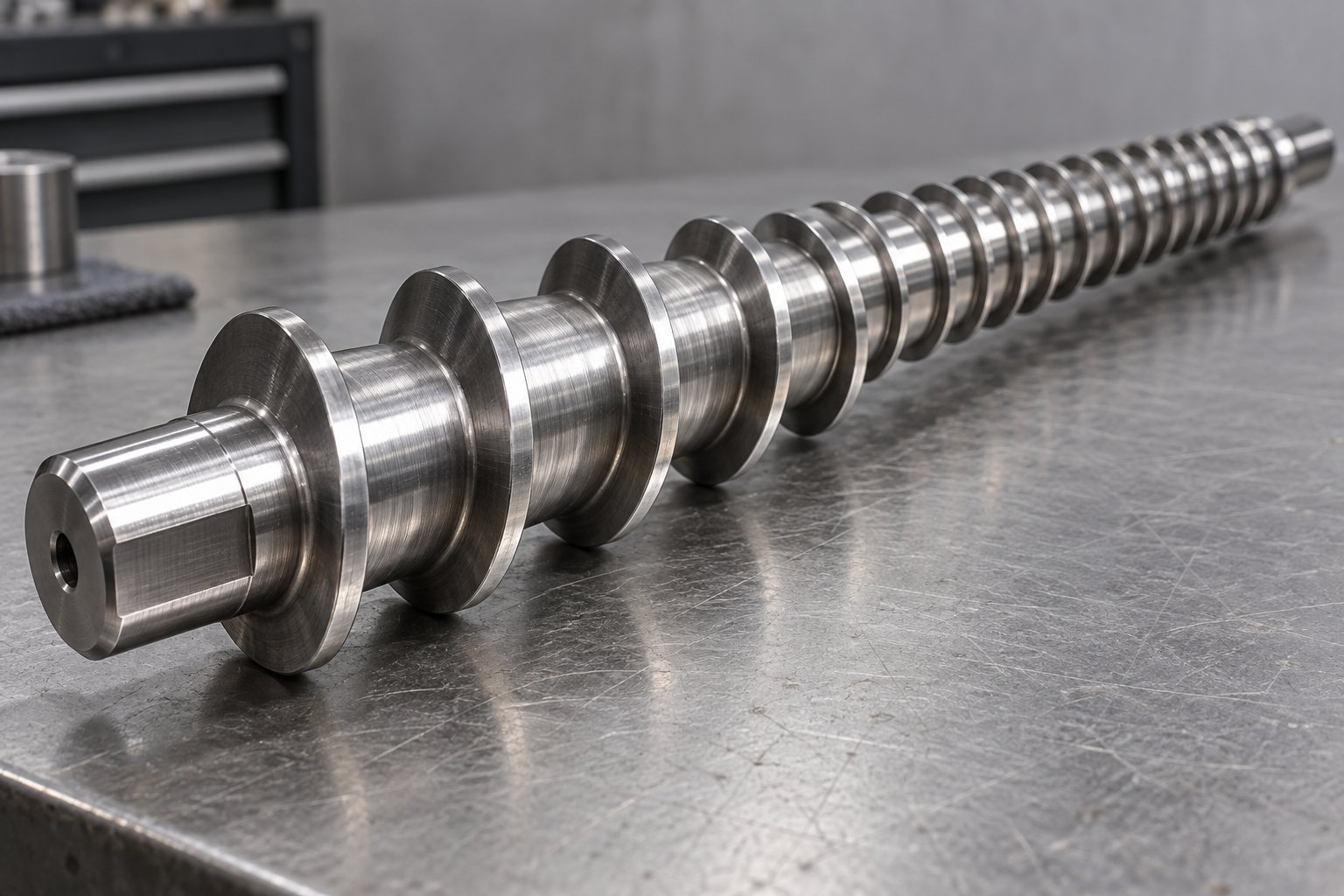
The extruder is the engine of the entire pipe extrusion line. At its center is a hardened steel barrel housing a precision-machined single screw. The screw's flight geometry - depth, pitch, and compression ratio - directly governs how polyethylene pellets are conveyed, melted, and pressurized. Get the screw design wrong, and you'll battle unmelted particles, inconsistent throughput, or excessive melt temperature for the life of the machine.
Driving that screw is a gearbox-motor assembly. The gearbox converts high-speed motor rotation into the low-speed, high-torque output the screw needs. A robust, hardened-gear reducer with a high torque rating ensures the screw can maintain steady rotation even under the heavy back pressure that PE pipe dies generate. Undersized gearboxes wear prematurely, introduce speed fluctuations, and ultimately show up as wall thickness variation in your finished product.
The motor itself matters more than many buyers realize. Modern PE extrusion lines increasingly use AC servo or permanent magnet synchronous motors for their wide speed range, high energy efficiency, and precise speed regulation. Motor power typically ranges from 37 kW for small-diameter lines up to 250 kW or more for machines producing large-bore pipes. The critical evaluation point is not just peak power but whether the drive delivers consistent torque across the entire screw speed range you'll use in production.
Die Head and Vacuum Calibration
Where the extruder creates molten polymer, the die head shapes it. The annular die consists of an outer ring and an inner mandrel that together form the gap through which the melt flows to create a hollow tube. Spiral mandrel designs are the standard in modern PE pipe production because they distribute the melt evenly around the full circumference, eliminating weak weld lines. Adjustable die lips let operators fine-tune wall thickness distribution without shutting down the line - a feature that pays for itself quickly in reduced scrap.
Immediately after the die, the vacuum calibration tank takes over. Inside, a precision sizing sleeve defines the pipe's outer diameter. Vacuum pressure draws the still-soft pipe outward against this sleeve, locking in roundness and OD accuracy. The sizing sleeves are interchangeable - swap them out to switch between different pipe diameters within the die head's range. Water jets inside the calibration tank simultaneously begin cooling the pipe's outer skin, initiating the crystallization process that gives PE its mechanical strength.
Calibration is where dimensional precision lives or dies. The vacuum level, water temperature, and sleeve condition must all stay within tight tolerances. Even a slightly worn or scratched sleeve can imprint surface marks on every meter of pipe it contacts, turning acceptable product into scrap. You'll want to evaluate the tank's vacuum regulation range (typically -0.02 to -0.08 MPa), the number of independent vacuum zones, and whether the sleeve mounting system allows fast changeover between sizes.
Cooling, Haul-Off, and Cutting Systems
After vacuum calibration, the pipe passes through one or more spray cooling tanks. These tanks use recirculating water systems that continuously pump, cool, and filter water before spraying it back onto the pipe. The number and length of cooling tanks depend on pipe diameter, wall thickness, and line speed - a large-diameter PE pipe might need 12 meters or more of cooling length to bring the wall temperature down uniformly. Insufficient cooling leads to internal residual stresses; overcooling wastes energy and floor space. Look for tanks with adjustable spray nozzle positions and independent temperature control per section.
The haul-off unit pulls the cooled pipe steadily through the entire downstream section. Most PE pipe lines use caterpillar-style haul-offs with multiple synchronized tracks that grip the pipe circumference. Modern designs equip each caterpillar with an independent permanent magnet servo motor, ensuring precise synchronization and a speed ratio range exceeding 50:1. That wide range is essential because the same line might run small-diameter pipe at 20 m/min one day and thick-walled large-diameter pipe at 0.5 m/min the next. Clamping force must be strong enough to maintain constant pull without deforming or marking the pipe surface - pneumatic or hydraulic adjustment systems make this tunable on the fly.
At the end of the line, a cutting system sizes every pipe to length. Smaller-diameter lines often use guillotine cutters for fast, clean cuts. For medium and large pipe, chipless planetary saws orbit around the pipe while traveling with it, so the extrusion never needs to stop. After cutting, rigid pipes transfer to a tilting stacker or dump table, while flexible small-diameter products below about 110-160 mm feed into an automatic coiler. The coiler must match extrusion speed precisely - any mismatch creates tension that deforms the freshly cut pipe end or disrupts the upstream haul-off.
| Component | Primary Function | Key Specification to Evaluate | Typical Range |
|---|---|---|---|
| Extruder (single screw barrel) | Melts and pressurizes PE resin into homogeneous melt | Screw diameter and L/D ratio | 45-120+ mm screw; 30:1 to 36:1 L/D |
| Gearbox | Converts motor speed to high-torque screw rotation | Torque rating (Nm) and gear ratio | Up to 30,000+ Nm; ratios from 5:1 to 20:1 |
| Drive motor | Powers screw rotation at adjustable speeds | Motor power (kW) and speed regulation accuracy | 37-250+ kW; speed accuracy within +/-0.1% |
| Die head and mandrel tooling | Shapes molten PE into hollow pipe profile | Pipe OD range and wall thickness adjustability | 16-1600 mm OD depending on die set |
| Vacuum calibration tank | Sizes and rounds the pipe to target OD | Vacuum range and number of sizing zones | -0.02 to -0.08 MPa; 1-3 vacuum zones |
| Spray cooling tanks | Removes residual heat to solidify pipe wall uniformly | Total cooling length and water temperature control | 4-12+ m per tank; water at 15-25 degrees C |
| Caterpillar haul-off | Pulls pipe at constant speed through downstream equipment | Number of caterpillars, speed range, and clamping force | 2-16 caterpillars; speed range 50:1+; force up to 50,000 N |
| Planetary saw / guillotine cutter | Cuts pipe to specified length without stopping the line | Maximum pipe OD capacity and cut quality | Up to 1600 mm OD; chipless or saw cut |
| Stacker / automatic coiler | Organizes finished pipe for packaging and transport | Maximum pipe weight/length or coil diameter | Stackers for rigid pipe up to 12 m; coilers for OD up to 160 mm |
Every component in this table feeds into or depends on its neighbors. The extruder's output rate dictates haul-off speed. The die head's pipe size range determines which calibration sleeves and cooling tank configurations you'll need. The haul-off's pulling force must match the pipe weight and friction through the cooling section. And the cutter's cycle time has to keep pace with the line speed without introducing vibration that travels backward through the still-warm pipe. This interconnectedness is exactly why evaluating a pe extrusion line component by component - rather than just comparing headline throughput numbers - gives you a far more accurate picture of what the equipment will actually deliver on the factory floor.
Specifications like screw diameter, L/D ratio, compression ratio, and motor power appear in every datasheet. But what do those numbers actually mean in practice - and which ones should carry the most weight in your purchase decision? That distinction matters far more than most buyers realize.
Key Technical Specifications and What They Mean
Open any equipment brochure for an HDPE pipe extrusion machine and you'll see a wall of numbers - 75 mm, 33:1, 3.2:1, 90 kW, 450 kg/hr. They look precise. They feel authoritative. But without context, they're just digits on a page. What actually makes a 33:1 L/D ratio better or worse than a 30:1 for your application? Why should a compression ratio of 3.5:1 concern you when processing PE100? These are the questions datasheets never answer - and they're exactly the questions that determine whether your line performs or underperforms.
Screw Diameter and L/D Ratio Explained
Screw diameter is the single specification that anchors every other parameter on an HDPE pipe extruder machine. It sets the baseline for throughput volume, barrel size, gearbox torque requirements, and ultimately, which pipe diameter range the machine can handle. Typical screw diameters for PE pipe production fall between 45 mm for small-bore lines producing pipes up to about 63 mm, and 120 mm or larger for heavy-duty lines extruding pipes beyond 800 mm OD.
The L/D ratio - the screw's working length divided by its diameter - tells you how much processing the polymer gets before reaching the die. A 75 mm screw with a 30:1 L/D is 2,250 mm long. Bump that to 33:1 and it's 2,475 mm. Those extra 225 mm might sound modest, but they provide additional residence time for the melt, improving temperature uniformity and homogeneity without cranking up the screw speed. For PE pipe applications, ratios of 30:1 to 36:1 are standard. Longer barrels allow gentler processing - lower screw RPM for equivalent output - which directly reduces shear heating and the risk of thermal degradation. You'll notice this matters most when running high-molecular-weight PE100 resins that are sensitive to excessive heat.
Compression Ratio and Barrel Zone Configuration
Compression ratio describes how much the screw channel depth shrinks from the feed zone to the metering zone. A ratio of 3:1 means the feed channel is three times deeper than the metering channel. Higher compression ratios generate more shear heat - useful for polymers that need aggressive melting, but risky for polyethylene. PE resins respond poorly to excessive shear because it degrades molecular chains and causes melt fracture on the pipe surface. Most PE pipe screws use compression ratios between 2.5:1 and 3.5:1, striking the balance between thorough melting and gentle material handling.
Barrel zone heating is equally critical. A modern HDPE extrusion machine divides the barrel into four to six independently controlled heating zones, each managed by its own PID temperature controller. Independent control means you can run a cooler feed section to optimize solid conveying, ramp up heat through the transition zone where melting happens, and then fine-tune the metering zone for uniform melt temperature. Without independent PID control per zone, temperature fluctuations cascade through the barrel, creating melt inconsistencies that show up as wall thickness variation or surface defects in the finished pipe.
Motor Power and Output Capacity Relationships
Motor power, screw speed, and throughput are three legs of the same stool. A bigger motor doesn't automatically mean more output - it means the drive can maintain torque at higher screw speeds or push through higher-viscosity melts without bogging down. For PE pipe extrusion, motor power typically ranges from 37 kW on small 45 mm lines to 250 kW or beyond for 120 mm+ machines. The practical metric to watch is specific energy consumption: how many kilowatt-hours the machine uses per kilogram of pipe produced. Efficient machines with optimized screw geometry and servo drives achieve 0.20-0.30 kWh/kg, while older or poorly configured equipment might burn 0.40 kWh/kg or more for identical output.
Output capacity, measured in kg/hr, depends on screw diameter, L/D ratio, screw speed, and the PE grade being processed. When comparing machines, don't just look at the maximum rated throughput - ask at what screw speed that figure is achieved. A machine hitting 500 kg/hr at 120 RPM has far more headroom and runs under less stress than one reaching the same number at 150 RPM. Lower operating speeds mean less wear, lower melt temperatures, and longer machine life.
| Specification | What It Means | Why It Matters | Typical Range for PE Pipe Machines |
|---|---|---|---|
| Screw Diameter | The outer diameter of the extruder screw, setting baseline capacity | Determines throughput volume, pipe size capability, and barrel/gearbox sizing | 45 mm to 120+ mm |
| L/D Ratio | Screw working length divided by its diameter | Longer ratios improve melt homogeneity and allow gentler processing at lower RPM | 30:1 to 36:1 |
| Compression Ratio | Feed channel depth divided by metering channel depth | Controls shear heat generation; too high risks degradation in PE resins | 2.5:1 to 3.5:1 |
| Barrel Heating Zones | Number of independently controlled temperature sections along the barrel | Enables precise temperature profiling for each stage of melting | 4 to 6 zones with independent PID control |
| Motor Power | Maximum power available to drive screw rotation | Must sustain torque across the full screw speed range without overloading | 37 kW to 250+ kW |
| Output Capacity | Maximum throughput measured in kilograms per hour | Must match target production volume; evaluate at which RPM it is achieved | 80 to 1,500+ kg/hr |
| Specific Energy Consumption | Energy used per kilogram of pipe produced (kWh/kg) | Directly impacts operating cost and indicates overall machine efficiency | 0.20 to 0.40 kWh/kg |
These specifications don't exist in isolation. A screw diameter sets the throughput ceiling, but the L/D ratio and compression ratio determine whether the melt arriving at the die is truly homogeneous - or carrying hidden problems that only show up after the pipe is installed. The motor and drive system must deliver steady torque across the speed range you'll actually use, not just at the peak number listed in a brochure. And barrel zone configuration determines whether you can dial in the precise thermal profile each PE grade demands. Speaking of grades - the resin you feed into the machine has its own molecular personality, and it changes everything about how these specifications need to be set.
How PE Material Grades Affect Extruder Machine Selection
Here is something datasheets almost never tell you: the polyethylene resin you feed into the hopper fundamentally changes how the entire machine needs to be configured. Two extruders with identical screw diameters, identical motors, and identical L/D ratios can produce vastly different pipe quality - simply because one is processing PE80 and the other is running PE100. The resin's molecular architecture dictates melt viscosity, heat sensitivity, crystallization speed, and flow behavior through the die. Ignore these differences, and you'll fight melt fracture, wall thickness inconsistency, and premature pipe failure no matter how expensive your equipment is.
PE63 Through PE100-RC and Their Processing Differences
Every PE pipe grade is classified by its Minimum Required Strength, or MRS - the hoop stress the material can sustain for 50 years of continuous pressure at 20 degrees C. The naming convention, defined by ISO 12162, simply multiplies the MRS by ten. So PE63 has an MRS of 6.3 MPa, PE80 reaches 8.0 MPa, and PE100 delivers 10.0 MPa. The number isn't marketing - it reflects real differences in molecular structure that directly affect how is HDPE manufactured on the extrusion floor.
PE63 resins feature a relatively simple, unimodal molecular weight distribution. They melt easily, flow predictably, and are forgiving to process - but their lower strength means thicker pipe walls are needed for any given pressure rating. PE63 is largely obsolete for pressure pipe applications, though you may still encounter it in legacy drainage systems.
PE80 introduced higher density and improved chain branching, boosting strength while remaining relatively straightforward to extrude. Most PE80 resins are unimodal or early-generation bimodal compounds. They tolerate a wider processing window than PE100, making them more forgiving for operators running older equipment. PE80 remains common in gas distribution mains and smaller-diameter pressure lines.
PE100 is where things get interesting - and demanding. To achieve that 10.0 MPa long-term strength, resin manufacturers engineered bimodal molecular weight distributions: a blend of short polymer chains for stiffness and crystallinity alongside very long chains for crack resistance and toughness. This bimodal structure gives extruded HDPE pipe exceptional performance in the ground, but it creates a narrower processing window on the machine. The high-molecular-weight fraction resists flow, increases melt viscosity, and makes the resin prone to melt fracture if barrel temperatures or screw speeds are even slightly off target. Screw geometry must deliver thorough homogenization without excessive shear - exactly the reason PE100 lines typically demand longer L/D ratios and carefully profiled compression zones.
PE100-RC (Resistant to Cracking) takes this further. It passes additional stringent slow-crack-growth tests, such as the Full-Notch Creep Test, making it the material of choice for trenchless installation methods like horizontal directional drilling and pipe bursting. From a processing standpoint, PE100-RC grades often have even higher molecular weight tails and tighter specifications on homogeneity. That translates to modified screw designs with enhanced mixing sections, slightly adjusted barrel temperature profiles, and closer monitoring of melt pressure at the die. The pipe carries the same pressure ratings as standard PE100 - the difference is durability under mechanical abuse, not a change in MRS class.
How Melt Flow Index Drives Machine Settings
If molecular weight distribution is the resin's personality, melt flow index is its behavioral fingerprint on the factory floor. MFI - measured in grams per 10 minutes under standardized load and temperature conditions - tells you how readily the polymer flows when molten. A lower MFI means higher melt viscosity, which means the extruder must work harder to push material through the die.
Imagine running a PE80 resin with an MFI of 0.8 g/10 min versus a PE100 grade at 0.2 g/10 min. That fourfold viscosity difference changes everything. The PE100 demands higher die pressure, generates more back pressure against the screw, and needs more carefully controlled barrel temperatures to avoid localized overheating. You'll typically need to reduce screw speed to prevent excessive shear while ensuring the barrel heaters provide enough energy to fully plasticate the stiffer melt.
Temperature profiles shift accordingly. For a PE80 pipe grade, barrel zone temperatures might range from 180 to 210 degrees C with a relatively flat profile. A PE100 bimodal resin often needs a more graduated approach - starting cooler in the feed and compression zones to manage shear heat, then rising to 200-230 degrees C in the metering zone and die head to ensure complete melt homogeneity and avoid shark-skin surface defects. Getting this profile wrong doesn't just hurt pipe appearance; it compromises the crystalline structure of the extruded polyethylene, undermining the very long-term strength the PE100 designation is supposed to guarantee.
| PE Grade | MRS (MPa) | Typical MFI Range (g/10 min) | Recommended Barrel Temp Range (degrees C) | Common Pipe Applications |
|---|---|---|---|---|
| PE63 | 6.3 | 0.8 - 1.5 | 170 - 200 | Legacy drainage and low-pressure systems (largely obsolete) |
| PE80 | 8.0 | 0.4 - 1.0 | 180 - 210 | Gas distribution, small-diameter water mains |
| PE100 | 10.0 | 0.2 - 0.5 | 190 - 230 | Municipal water trunk mains, gas networks, industrial pressure pipe |
| PE100-RC | 10.0 | 0.2 - 0.4 | 195 - 230 | Trenchless installations (HDD, pipe bursting), rocky terrain, sand-bed-free trenching |
Connecting Pipe Standards to Extruder Requirements
Material grade doesn't exist in a vacuum - it connects directly to the dimensional and pressure-rating standards your finished pipe must meet. And those standards set the tolerances your pe pipe extruder machine has to achieve, every meter, every shift.
ISO 4427:2019 governs polyethylene piping systems for water supply and specifies material grades (PE80 and PE100), SDR values, and dimensional tolerances. For example, a PE100 pipe rated at PN16 uses SDR 11 - meaning the outside diameter is exactly 11 times the minimum wall thickness. Achieving that wall thickness consistently requires the extruder, die head, vacuum calibration, and haul-off to work in tight coordination. A deviation of even 0.3 mm on a DN110 SDR 11 pipe wall can push the product out of specification.
EN 12201 provides equivalent requirements in European markets, harmonized with ISO 4427 but incorporating additional potable water safety requirements including migration limits for pipe materials in contact with drinking water. On the North American side, ASTM D3035 covers controlled outside-diameter PE pipe with its own dimensional tolerance tables, while ASTM D3350 classifies the resin itself by density, melt index, and slow crack growth resistance.
The practical takeaway? Your machine configuration must match both the PE grade you're processing and the standard your pipe must satisfy. A line designed primarily for PE80 gas pipe to ISO 4437 may lack the screw geometry, temperature control precision, or die head pressure capability to handle PE100 water pipe to ISO 4427 at the tightest SDR 11 tolerances. Conversely, a high-end PE100 line can typically step down to PE80 production with recipe adjustments - but the reverse rarely works without hardware changes.
This grade-to-machine relationship also shapes a more fundamental equipment decision: the type of extruder architecture itself. The molecular demands of PE100 bimodal resins, the throughput requirements for large-diameter pipe, and the growing use of recycled PE feedstock all push manufacturers toward different screw configurations - a choice that carries significant implications for capital cost, maintenance burden, and long-term production flexibility.
Single-Screw vs Twin-Screw Extruders for PE Pipe
Ask five different equipment suppliers whether you need a single-screw or twin-screw HDPE extruder, and you'll likely get five different answers - each conveniently pointing toward whatever machine they sell. It's one of the most common points of confusion for buyers entering PE pipe production, and almost no competitor content addresses it with any real technical depth. The truth is straightforward once you understand the engineering, but the reasoning matters far more than the conclusion alone.
Why Single-Screw Extruders Dominate PE Pipe Production
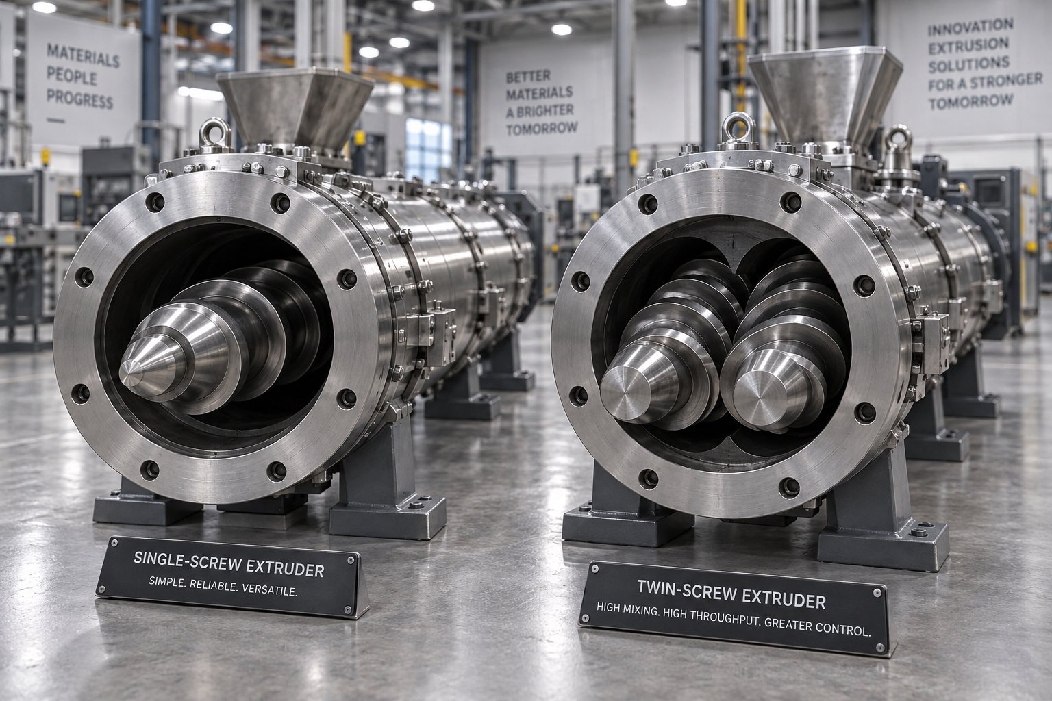
Walk into virtually any PE pipe manufacturing plant in the world, and you'll find single-screw extruders running the lines. This isn't tradition or inertia - it's engineering logic. Polyethylene is a semi-crystalline polyolefin that melts cleanly, flows predictably, and conveys efficiently as a solid pellet. These characteristics play directly to the strengths of a single-screw design.
Here's why. A single-screw HDPE extruder machine relies on drag-induced conveying: friction between the solid pellets and the barrel wall drives material forward, while the screw's progressive compression melts and pressurizes the polymer. For polyethylene - which has favorable friction characteristics against grooved barrel liners - this mechanism delivers highly efficient solid conveying and stable, consistent output. The melt generated in the transition zone is homogeneous enough for pipe production without the intense dispersive mixing a twin-screw provides, because PE pipe resin arrives as clean, pre-compounded pellets that don't need further blending.
Simplicity compounds the advantage. A single-screw system has one rotating element, one set of bearings, one gearbox interface, and a barrel that can be manufactured and maintained with well-established metallurgical techniques. Fewer moving parts mean fewer failure modes, lower capital cost, reduced energy consumption per kilogram of output, and significantly simpler maintenance routines. For a continuous process like HDPE extrusion - where lines run 24 hours a day, seven days a week - reliability isn't a nice-to-have. It's the foundation of profitability.
Energy efficiency reinforces the case. Single-screw extruders convert motor power into melt pressure more efficiently for polyolefins because the conveying mechanism itself generates much of the heat needed for melting. Twin-screw systems, by contrast, often require more motor power per kilogram of throughput because their intermeshing screws prioritize mixing intensity over conveying efficiency. When you're producing hundreds of tons of pipe per month, even a 10-15% difference in specific energy consumption translates into substantial annual savings.
When Twin-Screw Configurations Make Sense
Does that mean twin-screw extruders have no place in PE pipe production? Not quite - but their role is narrow and specific. Twin-screw systems excel when the incoming material needs intensive mixing, degassing, or compositional modification before it becomes a pipe. Think of scenarios like these:
- Recycled PE feedstock with variable properties - Post-consumer recycled HDPE often arrives with inconsistent melt flow indices, mixed polymer contamination, residual moisture, and varying degrees of molecular degradation. A co-rotating twin-screw extruder with modular kneading blocks and multiple venting zones can handle this variability, homogenizing disparate feedstock into a usable melt while removing volatiles and moisture that would create voids in the finished pipe.
- Compounding filled or reinforced PE materials - When the formulation calls for mineral fillers, flame retardants, or UV stabilizer masterbatches at high loading levels, a twin-screw design provides the dispersive and distributive mixing needed to achieve uniform filler distribution throughout the polymer matrix.
- Specialty co-extrusion applications - Multi-layer pipe systems incorporating PE with barrier layers sometimes use twin-screw extruders for specific layers that require in-line blending or reactive processing.
In practice, many recycled-PE pipe operations use a two-stage approach: a twin-screw extruder compounds and pelletizes the recycled material first, and then a single-screw extruder processes those uniform pellets into pipe. This separates the compounding challenge from the pipe-forming challenge, letting each machine type do what it does best.
| Feature | Single-Screw Extruder | Twin-Screw Extruder |
|---|---|---|
| Throughput efficiency for PE pipe | High - optimized drag conveying for polyolefins delivers consistent, high-volume output | Moderate - mixing-focused design prioritizes blending over raw conveying capacity |
| Melt homogeneity (virgin PE pellets) | Excellent - adequate for pre-compounded PE pipe grades (PE80, PE100) | Superior mixing capability, but unnecessary for clean virgin resin |
| Suitability for recycled/variable feedstock | Limited - struggles with inconsistent melt behavior and contamination | Excellent - modular screw configurations handle variable viscosity, degassing, and contaminant management |
| Maintenance complexity | Lower - single screw, fewer wear components, simpler gearbox | Higher - intermeshing screw elements, complex gearbox, more wear surfaces |
| Energy consumption (kWh/kg) | Lower (typically 0.20-0.30 kWh/kg for PE pipe) | Higher (typically 0.25-0.40 kWh/kg depending on configuration) |
| Capital cost | Lower - simpler design and manufacturing | Significantly higher - 1.5x to 3x the cost of comparable single-screw systems |
| Continuous pipe extrusion reliability | Proven - decades of 24/7 production track record | Better suited to batch compounding than continuous pipe forming |
| Best application in PE pipe context | Primary pipe extrusion from virgin or pre-compounded pellets | Upstream compounding of filled, recycled, or specialty PE materials |
The Critical Role of the Screw Barrel in Pipe Quality
Whether you run a single-screw or twin-screw system, one truth holds: the screw and barrel are where pipe quality is made or lost. Every kilogram of PE that becomes pipe passes through this metal-on-metal interface, and its condition determines output consistency, energy efficiency, and machine longevity. Yet many operators treat the screw barrel as a set-and-forget component - right up until declining performance forces their hand.
Screw barrel metallurgy matters more than most buyers appreciate. The barrel's inner lining faces constant abrasive contact with solid pellets in the feed zone and pressurized melt in the metering zone. For PE pipe applications - where the resin itself isn't highly abrasive - the primary wear drivers are regrind contaminants, pigment carriers, and the occasional tramp metal particle that slips past magnetic separators. High-quality barrels use centrifugally cast bimetallic linings with elevated tungsten carbide content, providing hardness and wear resistance that can double or triple service life compared to nitrided steel alternatives.
The screw itself requires compatible hardfacing on the flight lands. Compatibility between screw hardfacing and barrel lining alloys isn't optional - mismatched metallurgies cause galling, where the softer metal microscopically welds to the harder surface, tears away, and accelerates destruction of both components. As clearance between the screw flight OD and barrel ID increases beyond the original 0.001 inch per side per inch of diameter, melt leaks backward over the flights. The result? Declining throughput at the same screw speed, rising motor amperage, increased melt temperature from reprocessed material, and eventually visible quality defects like streaking, gels, or wall thickness variation in the finished pipe.
Surface treatments and precision manufacturing add further performance layers. Chrome plating or specialized nitriding on the screw surface reduces polymer adhesion and improves cleanability during material changeovers. Barrel bore concentricity and straightness - measured in thousandths of an inch - determine how evenly the screw rotates within the barrel, directly affecting wear patterns and melt uniformity. These are details that separate a component engineered for pipe extrusion from a generic replacement part.
This is exactly where sourcing decisions become strategic. When a worn barrel needs replacement, the instinct is often to buy the cheapest available option or to consider replacing the entire extruder. Neither is ideal. Precision-manufactured replacement barrels from specialists like NANHAIYA - who engineer custom single screw barrels specifically for pipe, film, sheet, and recycling extrusion applications - can restore original clearances and output consistency at a fraction of full machine replacement cost. The key is specifying the correct bimetallic alloy, bore tolerance, and overall length to match your existing machine and the PE grades you process. A well-sourced replacement barrel extends machine life by years and eliminates the gradual performance erosion that eats into margins long before anyone notices the numbers trending downward.
Ultimately, the single-screw versus twin-screw question for PE pipe production has a clear default answer - single-screw wins for the vast majority of applications. But whichever architecture you run, the screw barrel is the wear component that demands the most attention, the smartest material selection, and the most disciplined replacement strategy. Get that right, and you protect the investment in every other component on the line. Get it wrong, and no amount of downstream equipment quality can compensate for a melt that arrives at the die head inconsistent, overheated, or under-pressurized.
Choosing between extruder architectures, though, is only one piece of the machine selection puzzle. The pipe diameter range you need to produce, the throughput targets you're chasing, and the total cost picture beyond the purchase price all shape the decision in ways that a spec sheet comparison alone can't capture.
How to Choose the Right PE Pipe Extruder Machine
You've seen the specifications. You understand the process. You know which PE grades you'll run and which screw architecture fits. But here's the question that ties it all together: how do you actually select the right machine for your specific production goals? Surprisingly, most buyers start by comparing headline numbers - screw diameter, motor power, maximum output - and end up with a line that's either oversized for their needs or struggling to keep pace with demand within six months of installation. A smarter approach works backward from what you need to produce and builds the equipment specification from there.
Matching Extruder Size to Pipe Diameter Range
Your target pipe diameter range is the single most important starting point. It dictates everything downstream - screw size, die head tooling, calibration tank dimensions, cooling length, haul-off capacity, and cutter selection. Get this wrong, and the entire pe pipe production line is either constrained or wastefully oversized.
Think of it in three broad tiers:
- Small-bore lines (16-63 mm OD) - These pipes are lightweight, fast-running, and often coiled rather than cut to length. A 45-60 mm screw diameter extruder typically handles this range, with output requirements in the 80-200 kg/hr bracket. Die heads are compact, calibration tanks shorter, and line speeds can exceed 15-20 m/min. These lines suit irrigation, telecom ducting, and underfloor heating applications.
- Mid-range lines (75-250 mm OD) - The workhorse tier for municipal water distribution and gas mains. Screw diameters of 60-90 mm are common, and output demands climb to 200-600 kg/hr depending on wall thickness. Cooling tank length increases significantly, haul-off force requirements grow, and planetary saws replace simple guillotine cutters for clean cuts on thicker walls.
- Large-diameter lines (315-1600 mm OD) - Heavy infrastructure pipe for trunk water mains, sewer force mains, and industrial applications. These lines require 90-120 mm+ screw diameters, output capacities from 500 to well over 1,500 kg/hr, and massive downstream equipment. Cooling sections can stretch 20 meters or more, and haul-off units need multiple caterpillar stages with high clamping force to move pipe that weighs 60+ kg per meter.
The relationship is direct but not linear. A 315 mm SDR 11 pipe has a nominal wall of about 28.6 mm and an estimated mass around 24.6 kg per meter - demanding roughly 737 kg/hr of extruder output at just 0.5 m/min line speed. Compare that to a 110 mm SDR 17 pipe at only 2.0 kg/m, needing about 121 kg/hr at the same speed. The pipe diameter and SDR combination you target doesn't just influence machine size - it defines an entirely different scale of production equipment.
Production Volume and Throughput Planning
Knowing your pipe size range is necessary, but it's not sufficient. You also need to calculate whether a single polyethylene pipe production line can meet your volume targets - or whether parallel lines make more operational and financial sense.
Start with a straightforward formula. Required extruder output equals the pipe's mass per meter, multiplied by your target line speed, multiplied by 60 to convert to kg/hr. For solid-wall PE pipe, mass per meter can be estimated using the standard engineering formula based on outer diameter, wall thickness, and compound density - typically around 955 kg/m³ for HDPE, though you should confirm the certified value for your specific resin.
Consider a practical example. You need to produce 110 mm SDR 11 PE100 water pipe with a 10.0 mm wall. At a line speed of 1.0 m/min, that's roughly 180 kg/hr of required output. A mid-range extruder with a 75 mm screw handles this comfortably. But if your order book also includes 315 mm SDR 17 pipe at 18.5 mm wall thickness, you'll need about 494 kg/hr at 0.5 m/min - pushing you toward a larger machine or a second dedicated line. Trying to cover both extremes on one line means the extruder is either loafing at low output on the small pipe or maxed out on the large pipe, neither of which is efficient.
Daily production targets add another layer. If your facility needs to ship 20 tons of 250 mm pipe per day, running 22 hours of effective production time, you need roughly 910 kg/hr sustained output - accounting for changeover time, startup scrap, and scheduled maintenance windows. Always build in a 15-20% output margin above your calculated minimum. A machine running at 95% of its rated capacity around the clock wears faster, runs hotter, and leaves zero headroom for the heavier SDR products your customers will inevitably request.
Budget Considerations Beyond the Purchase Price
Here's where many first-time buyers get caught off guard. The purchase price of a pe pipe extruder machine - while significant - represents only a fraction of the total cost of ownership over the machine's 15-20 year productive life. Focusing solely on sticker price is like buying a truck based on the showroom tag without asking about fuel economy, tire wear, or insurance.
The real cost picture includes several categories that rarely appear in initial quotations:
- Installation and commissioning - Foundation work, electrical connections, water supply for cooling systems, compressed air supply, material handling infrastructure, and the commissioning engineer's time to achieve stable production on your specific pipe sizes and PE grades.
- Die head tooling sets - Each pipe diameter range requires its own die and mandrel set, plus matching calibration sleeves. A line covering five different OD sizes might need five complete tooling sets, each costing a meaningful percentage of the base machine price. Confirm tooling cost and lead time upfront.
- Operator training - PE pipe extrusion demands skilled operators who understand temperature profiling, screw speed optimization, and quality monitoring. Training programs - whether provided by the equipment supplier or third-party specialists - are an investment, not an optional extra.
- Energy operating costs - A machine consuming 0.35 kWh/kg versus one at 0.22 kWh/kg costs dramatically more to run over thousands of production hours. At an output of 500 kg/hr running 8,000 hours per year, that 0.13 kWh/kg gap represents 520,000 kWh annually - potentially tens of thousands of dollars depending on your electricity rate.
- Spare parts sourcing and availability - Heater bands, thermocouples, drive belts, seals, and gearbox components all wear over time. Critical spares - especially screw and barrel replacements - can have lead times of 8-12 weeks from some manufacturers. Evaluate whether the supplier stocks common parts regionally or whether every order ships from overseas with customs delays built in.
- Changeover time and flexibility - If your product mix includes multiple pipe diameters and SDR ratings, the time required to switch between products directly affects productive uptime. Lines designed for fast changeover - with quick-change die heads, adjustable calibration sleeves, and recipe-driven control systems - recover their premium through higher utilization rates.
A useful rule of thumb: budget roughly 30-50% of the base machine cost for tooling, installation, training, and first-year spare parts inventory. That doesn't mean the cheapest machine is always the worst deal or the most expensive is always the best - it means comparing machines on purchase price alone guarantees you're missing the variables that actually determine profitability.
Before committing to any purchase, consolidate your requirements into a structured evaluation checklist:
- Complete diameter and SDR matrix for all products you plan to produce
- PE grade specifications (PE80, PE100, PE100-RC) and applicable product standards (ISO 4427, EN 12201, ASTM D3035)
- Target throughput per product, calculated from mass per meter and planned line speed
- Maximum and minimum pipe OD the line must cover without hardware changes
- Required tooling sets and their included versus optional pricing
- Guaranteed output on the heaviest product at stable, documented conditions
- Specific energy consumption (kWh/kg) at typical operating points
- Spare parts pricing and lead times for screw, barrel, gearbox components, and die wear items
- Supplier's commissioning scope, warranty terms, and post-sale technical support structure
- Cooling water supply requirements and available utilities at your facility
Requesting that suppliers quote against this standardized checklist - rather than letting each one define the comparison in their own terms - levels the playing field. It also quickly reveals which suppliers understand PE pipe extrusion deeply and which are simply reselling generic equipment with pipe tooling bolted on.
Selecting the right machine, though, is only half the equation. Keeping it running at peak performance year after year demands a maintenance discipline that most equipment manuals barely scratch the surface of - starting with the wear components that silently erode output quality long before anyone notices the numbers slipping.
Maintenance and Troubleshooting Best Practices
A pe pipe extruder machine doesn't fail all at once. It degrades in whispers - a fraction of a kilogram per hour less throughput this month, a slight uptick in motor amperage next month, a barely noticeable change in pipe surface gloss the month after that. By the time the decline becomes obvious enough for someone to raise a flag, weeks or months of suboptimal production have already eaten into margins. The difference between a line that runs profitably for 15 years and one that becomes a constant headache after five almost always comes down to maintenance discipline - specifically, knowing what to check, how often to check it, and what the numbers actually mean.
Preventive Maintenance Schedules for Maximum Uptime
Effective maintenance on an hdpe extrusion line isn't about overhauling equipment on a fixed calendar. It's about structured inspection rhythms that catch drift before it becomes downtime. A practical approach breaks tasks into daily, weekly, monthly, and annual cycles - each targeting different failure modes and wear patterns across the entire line.
Daily checks should take 10-15 minutes per shift. They aren't deep repair work; they're a structured walk-through confirming the line is still inside its normal operating window. Weekly inspections happen during planned downtime - die changes, material switches, or scheduled production gaps - and focus on wear points invisible during normal operation. Monthly records build the trend data that transforms reactive repair into proactive planning.
- Daily: Listen for abnormal motor or gearbox noise; verify actual barrel zone temperatures match setpoints within +/-2 degrees C; record melt pressure at a fixed screw speed; inspect die lips and adapter joints for buildup or leakage; confirm feed-throat cooling flow; check cooling water level, temperature, and spray coverage; verify haul-off belt contact and displayed speed; inspect cutter blade condition and cut quality; review alarm history on the HMI.
- Weekly: Check gearbox oil level, color, and foaming; inspect heater-band terminals for discoloration or looseness; spot-check die bolt torque (thermal cycling loosens fasteners); clean water circuit strainers, filters, and spray nozzles; inspect vacuum calibration seals and sleeve surfaces; measure haul-off belt wear and verify encoder feedback; sharpen or replace cutter blades; clean electrical cabinet VFD heat sinks and tighten sample terminal connections.
- Monthly: Measure screw and barrel clearance at feed, transition, and metering sections and record trends; log gearbox oil temperature under stable load; test motor insulation resistance; compare vacuum pump ultimate vacuum against baseline; record cooling system delta-T and water quality (hardness, conductivity); measure cut-length variation over 10+ samples; back up PLC, HMI, and VFD parameters.
- Annually: Full thermocouple calibration against traceable standards; comprehensive gearbox oil analysis (particle count, viscosity, moisture content); die head disassembly, cleaning, and flow-channel inspection; barrel heater continuity and wattage verification; cooling pump and vacuum pump bearing inspection or replacement; full electrical cabinet inspection including grounding integrity.
A daily checklist is strongest when operators record only abnormal items - keep the form short enough that it actually gets completed every shift. The monthly records matter most strategically: if melt pressure, gearbox temperature, cooling delta-T, or screw clearance moves in the wrong direction for two or three consecutive readings, you schedule the repair before the line forces the schedule for you.
Recognizing and Addressing Screw and Barrel Wear
Of all the maintenance concerns on a PE pipe extrusion line, screw and barrel wear ranks at the top. Every kilogram of polyethylene that becomes pipe passes through this metal-on-metal interface, and as the clearance between screw flight tips and barrel bore grows, so do the problems. Melt leaks backward over the flights, reducing pumping efficiency. Operators compensate by increasing screw speed or barrel temperature, which raises energy consumption and melt temperature while accelerating further wear. It's a self-reinforcing cycle that quietly erodes production economics long before the damage becomes visible.
What drives the wear? For PE pipe applications, the resin itself is relatively gentle on metal surfaces. The real culprits are contaminated regrind containing sand, metal particles, or incompatible polymer fragments; pigment concentrate carriers with abrasive fillers; and corrosive byproducts from UV stabilizer or flame-retardant additive packages. Abrasive wear rounds flight edges and enlarges the barrel bore, while corrosive attack pits metal surfaces in localized zones - particularly around vented sections or areas where degradation products concentrate.
You'll notice several warning signs before wear reaches critical levels:
- Declining throughput at constant screw speed - If kg/hr per RPM drops steadily over months, increasing clearance is allowing more melt to flow backward rather than forward.
- Rising melt temperature without setpoint changes - Material being reprocessed (leaked back and re-sheared) absorbs additional energy, pushing actual melt temperature above what barrel heater settings should produce.
- Increasing motor amperage at steady output - The extruder works harder to maintain throughput as pumping efficiency declines.
- Visible streaking, gels, or discoloration in the pipe wall - Material trapped in enlarged clearances experiences extended residence time and thermal degradation, showing up as brown streaks or gel particles.
- Wall thickness variation that doesn't respond to die adjustment - When the melt arriving at the die head is no longer pressure-stable, no amount of die-bolt tweaking can produce uniform walls.
These symptoms don't automatically prove wear - hopper bridging, a blocked screen pack, a failed heater, incorrect thermocouple reading, wet resin, or gearbox damage can produce similar results. That's why measurement is essential. Use a calibrated bore gauge to measure barrel internal diameter at defined axial positions and multiple angular orientations. Measure screw flight outside diameter at corresponding locations. The diametral clearance equals measured barrel ID minus measured screw OD.
There is no universal replacement threshold - allowable clearance depends on screw diameter, polymer viscosity, operating pressure, and product tolerance requirements. A clearance acceptable on a large low-pressure drainage line may be unacceptable on a small precision pipe extruder running tight SDR 11 tolerances. The most reliable approach uses evidence in this order: the OEM's published limits, new-condition baseline measurements documented during commissioning, and tracked trend data showing the rate of clearance increase between inspections.
When replacement is warranted, evaluate the screw and barrel as a matched pair. A new screw installed into a badly worn barrel - or a new barrel around a severely worn screw - leaves excessive clearance and shortens the life of the new component. Precision-manufactured replacement barrels from specialists like NANHAIYA, who engineer custom single screw barrels for pipe, film, sheet, and recycling extrusion applications, can restore original clearances and output consistency without full machine replacement. The critical specifications to match include bimetallic alloy composition suited to your PE grades and additives, bore tolerance to pair correctly with the new or rebuilt screw, and overall barrel length and flange dimensions compatible with your existing extruder frame. A well-sourced replacement barrel minimizes downtime and restores production efficiency - often extending the productive life of the entire line by years.
Troubleshooting Common PE Pipe Extrusion Defects
Even with a solid maintenance program, defects happen. The key is connecting what you see in the finished pipe to what's going wrong inside the machine - quickly, systematically, and without chasing false leads. Here are the most common quality issues in extruded pipe manufacturing and their probable machine-side root causes.
Melt fracture and shark skin. These surface defects appear as a rough, matte, or regularly patterned texture on the pipe's outer surface. They originate at the die exit, where the molten PE's elastic recovery creates flow instabilities as it crosses the die lip. Machine-side causes include excessive die-zone temperature differential, a die land length too short for the melt velocity, or screw speed too high for the resin's melt flow index. Corrective actions: reduce line speed to lower shear rate at the die lip, raise die-zone temperature by 5-10 degrees C to reduce melt elasticity, verify thermocouple accuracy in the die-head zones, and polish die lips to remove buildup that disrupts laminar flow. For PE100 bimodal resins, which are inherently more susceptible, confirm that barrel temperature profiling is gradual enough to fully homogenize the high-molecular-weight fraction before it reaches the die.
Wall thickness variation. Inconsistent wall thickness - whether circumferential (thick on one side, thin on the other) or longitudinal (fluctuating along the pipe's length) - ranks among the most costly defects because it can push an entire production run out of specification. Circumferential variation usually traces to a misaligned or unevenly adjusted die, worn mandrel support components, or barrel-to-die adapter misalignment. Longitudinal variation points to unstable extruder output - typically from feed surging, inconsistent pellet feeding, screw or barrel wear reducing pumping stability, or haul-off speed fluctuation. Switching from volumetric to gravimetric feeding can reduce feed-related variability by as much as 70%. When inline laser micrometry is available, use it to identify the variation pattern before opening the die head.
Ovality. When a pipe's cross-section is oval instead of round, the cause almost always lies in the vacuum calibration or cooling system rather than the extruder itself. Uneven vacuum distribution within the sizing sleeve, worn or damaged sleeve surfaces, asymmetric spray cooling, or insufficient cooling length all contribute. In some cases, a haul-off with unequal clamping force across the caterpillar tracks deforms the pipe after it exits calibration but before the wall is fully rigid. Check calibration sleeve condition first, then verify vacuum uniformity across all zones, and finally confirm that cooling water flow is evenly distributed around the pipe circumference.
Internal voids and bubbles. Voids within the pipe wall indicate trapped gas - usually from moisture in the resin, volatile additives, or air entrapment during feeding. Pre-dry PE resin if moisture content exceeds 0.03%, verify hopper sealing and material handling hygiene, and check for bridging or rat-holing in the feed throat that could intermittently starve the screw and entrain air. If voids appear only when using regrind, the recycled material likely contains residual moisture or volatile contamination that requires more aggressive pre-drying or a vented barrel section.
Discoloration and black specks. Yellow or brown discoloration signals thermal degradation - the polymer is spending too long at too high a temperature somewhere in the melt path. Common culprits include dead spots in the die head where material stagnates and degrades, excessive barrel temperatures, a damaged or worn screw that creates localized high-shear zones, or inadequate purging between material changeovers. Black specks are often carbonized fragments of degraded polymer breaking free from accumulated deposits inside the barrel, screen changer, or die flow channels. Systematic die head disassembly and cleaning, combined with proper purging protocols, resolves most cases.
| Defect | What You See | Most Likely Machine-Side Cause | First Corrective Action |
|---|---|---|---|
| Melt fracture / shark skin | Rough, matte, or patterned outer surface | Excessive shear at die exit; die lip buildup; incorrect die temperature | Reduce line speed; raise die temperature 5-10 degrees C; polish die lips |
| Wall thickness variation (circumferential) | Thick-thin asymmetry around pipe cross-section | Die misalignment; uneven die gap; adapter eccentricity | Check and recenter die; inspect mandrel support; verify adapter alignment |
| Wall thickness variation (longitudinal) | Periodic or random thickness fluctuation along pipe length | Feed surging; screw/barrel wear; haul-off speed instability | Switch to gravimetric feeding; measure screw-barrel clearance; check haul-off servo |
| Ovality | Out-of-round cross-section exceeding tolerance | Worn calibration sleeve; uneven vacuum; asymmetric cooling | Inspect and replace sizing sleeve; equalize vacuum zones; balance spray coverage |
| Internal voids / bubbles | Hollow spots or gas pockets within pipe wall | Moisture in resin; air entrapment at feed; volatile contamination in regrind | Pre-dry resin below 0.03% moisture; check hopper seal; inspect feed-throat condition |
| Discoloration / black specks | Yellow-brown streaks or dark particles in pipe wall | Thermal degradation in dead spots; excessive barrel temperature; stale material deposits | Clean die head flow channels; verify barrel temperature profile; purge thoroughly |
One final principle ties maintenance and troubleshooting together: trend data beats intuition. A single melt pressure reading or one clearance measurement tells you the current state - repeated readings over weeks and months tell you where the hdpe pipe extrusion line is heading. Track kg/hr per RPM, specific energy in kWh/kg, actual melt temperature versus setpoint, reject rate by defect type, and screw-barrel clearance at each inspection. When two or three of these metrics drift in the wrong direction simultaneously, you don't have a mystery - you have a maintenance event waiting for a calendar slot. And that proactive approach is exactly what separates high-uptime operations from facilities that lurch from one emergency repair to the next.
Maintaining what you have, though, is only part of the long-term picture. The newest generation of PE pipe extrusion equipment is shifting the entire cost equation - from servo drive systems that cut energy consumption per kilogram, to inline sensors that detect wall thickness deviations in real time, to multi-layer co-extrusion architectures opening entirely new product categories. Those technologies aren't future concepts anymore - they're running in production facilities right now.
Energy Efficiency and Emerging Extrusion Technologies
Energy is the silent line item that never stops growing. For an HDPE plant running a pe pipe extruder machine 8,000 hours per year at 500 kg/hr output, even a modest 0.05 kWh/kg improvement in specific energy consumption saves 200,000 kWh annually - enough to shift the competitive math on every meter of pipe you produce. Yet most buyers still evaluate equipment almost entirely on throughput and purchase price, treating energy performance as an afterthought. That's changing fast. The latest generation of extrusion technology attacks energy waste from multiple angles simultaneously, while digital monitoring systems give operators visibility into process variables that were invisible just a decade ago. And on the product side, multi-layer co-extrusion is opening pipe categories that single-layer lines simply can't serve.
Energy-Saving Technologies in Modern Extruders
Where does energy actually go in a pipe extrusion line? Roughly 60-70% is consumed by the extruder drive motor. Another 15-20% goes to barrel and die heating. The remainder splits among cooling pumps, vacuum systems, haul-off drives, and auxiliaries. Reducing the biggest slice - drive energy - delivers the fastest payback, but gains compound when you address multiple systems together.
Grooved feed barrel sections represent one of the most impactful upgrades available. As discussed earlier in the extrusion process, axial grooves machined into the barrel liner at the feed throat dramatically increase solid conveying efficiency by forcing pellets forward rather than allowing them to rotate with the screw. The practical result? Equivalent throughput at significantly lower screw speed. Case studies comparing a 90 mm groove feed extruder against a 114 mm smooth bore extruder processing high-viscosity HDPE at identical output rates showed the groove feed design achieved lower melt temperatures and reduced power consumption - translating to annual energy savings of 268,000 to 388,000 kWh depending on the resin grade. That's a cost reduction of $26,800 to $38,800 per year at just $0.10/kWh, with a proportional cut in CO2 emissions exceeding 227,000 pounds annually. Even more striking, the groove feed extruder accomplished this with a smaller screw diameter, meaning a smaller motor, a smaller gearbox, and a smaller machine footprint.
High-efficiency servo drive motors are replacing older vector AC drives across the industry - and the difference isn't subtle. Permanent magnet synchronous motors paired with matched servo inverters deliver 10-15% higher energy efficiency across the operating speed range compared to conventional induction motors. They maintain full torque at low speeds without the thermal penalties that force older drives to derate, which matters enormously on large-diameter lines where screw speeds drop to 20-40 RPM for thick-walled pipe. The wider speed range also eliminates the need for mechanical gearbox ratio changes when switching between small and large pipe products on the same line.
Optimized screw geometries contribute their own energy savings by reducing unnecessary shear heating and back pressure. Barrier flight designs that separate solid and melt phases earlier in the barrel reduce the work the metering section must perform. Mixing sections engineered specifically for polyolefin viscosity profiles homogenize the melt without the aggressive kneading that wastes motor energy on polymers that don't need it. The result is lower melt temperatures at equivalent output - which not only saves drive energy but also reduces cooling demand downstream.
On the heating side, ceramic infrared barrel heaters with insulation jackets are displacing traditional mica band heaters. Infrared elements transfer heat more efficiently into the barrel wall, and insulation jackets cut radiated heat loss by up to 30-40%. The combination reduces heater energy consumption while also keeping the production environment cooler - a secondary benefit that lowers HVAC costs in enclosed facilities.
Cooling systems, often overlooked in energy discussions, offer substantial savings through variable-speed water pumps and closed-loop temperature control. Traditional systems run pumps at full speed continuously, throttling flow with valves. Variable-frequency drives on cooling pumps adjust speed to match actual heat-removal demand, cutting pump energy consumption by 30-50% during lighter-load production runs. Closed-loop cooling circuits with plate heat exchangers also reduce water consumption and improve temperature stability compared to open-tower systems.
- Grooved feed barrel sections - Enable equivalent output at lower screw speed; documented savings of 268,000-388,000 kWh/year on a single line processing HDPE at 1,100 lb/hr
- Permanent magnet servo drive motors - 10-15% efficiency gain over conventional AC induction drives; full torque at low RPM without derating
- Optimized barrier screw geometries - Reduce shear heating and back pressure, lowering melt temperature 5-15 degrees C at equivalent throughput
- Ceramic infrared barrel heaters with insulation jackets - Cut heating zone energy consumption 20-40% versus traditional mica band heaters
- Variable-speed cooling water pumps - Reduce pump energy consumption 30-50% by matching flow to actual thermal demand
- Closed-loop cooling circuits - Stabilize water temperature, reduce waste, and lower total cooling system energy draw
Taken individually, each upgrade delivers meaningful savings. Combined across a full energy efficient pipe extrusion line, the cumulative impact can reduce specific energy consumption from the 0.35-0.40 kWh/kg range typical of older equipment to 0.20-0.25 kWh/kg on a modern system - a reduction that pays for the technology investment within two to four years at current electricity rates.
Inline Quality Monitoring and Industry 4.0 Integration
Imagine catching a wall thickness deviation the instant it begins - not after 200 meters of out-of-spec pipe have already been extruded, cooled, and cut. That's exactly what inline monitoring systems deliver, and they're rapidly becoming standard equipment rather than optional extras on modern PE pipe lines.
Ultrasonic wall thickness measurement is the centerpiece. Sensors mounted directly on the calibration or cooling section continuously measure wall thickness at multiple points around the pipe circumference - typically 4, 8, or even 16 measurement points depending on the system. The data feeds back to the line controller in real time, allowing automatic correction via die centering adjustments, haul-off speed trim, or operator alerts. As pipe extrusion specialists note, these scanners enable production closer to the minimum required wall thickness, directly reducing material overweight. Saving just 1-2% of raw material through tighter wall thickness control can pay back the scanner investment in less than one year - a compelling return on what many buyers still consider an accessory.
Gravimetric dosing systems with automatic recipe management replace volumetric feeders on advanced lines. Instead of metering pellets by volume - which varies with pellet size, bulk density, and hopper level - gravimetric systems weigh material in real time and adjust feed rate to maintain a target mass flow. When integrated with the line controller, recipe management automates material changeovers: select the target pipe product from a database, and the system adjusts feed rate, barrel temperature profile, screw speed, haul-off speed, and vacuum setpoints in coordinated sequence. This reduces changeover time, eliminates operator guesswork, and ensures every production run starts from a validated parameter set.
Melt pressure and temperature sensors positioned at the barrel end, screen changer, and die head provide continuous insight into the extrusion process state. Trend analysis of melt pressure at constant screw speed reveals gradual screen blockage, screw wear, or feed inconsistencies before they manifest as pipe defects. Melt temperature sensors - preferably flush-mounted infrared types that measure actual polymer temperature rather than barrel wall temperature - confirm that the thermal profile matches the recipe and flag deviations within seconds.
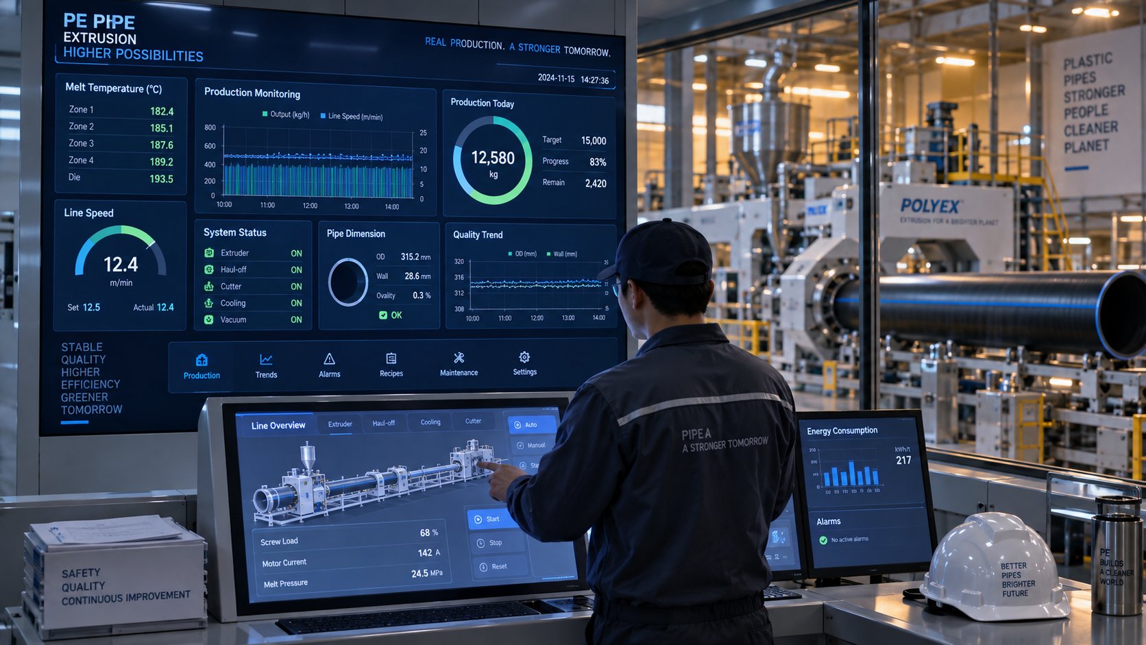
All of these data streams converge on centralized production dashboards - the Industry 4.0 integration layer. Modern SCADA and MES platforms aggregate extruder parameters, downstream equipment status, quality measurements, energy consumption, and production counts into unified displays accessible from control rooms, offices, or mobile devices. Historical data logging enables shift-to-shift and batch-to-batch comparisons, supporting root cause analysis when quality issues arise. Some systems incorporate machine learning algorithms that correlate process variable patterns with downstream quality outcomes, flagging anomalous conditions before defects appear in the finished pipe.
The practical impact is significant. Operators spend less time reacting to problems and more time optimizing. Reject rates drop because deviations are caught and corrected in real time. Material consumption decreases because wall thickness stays closer to the minimum specification. And maintenance becomes predictive rather than reactive, because trend data reveals equipment degradation weeks before it causes downtime.
Multi-Layer Co-Extrusion and Next-Generation Pipe Systems
Single-layer PE pipe covers the vast majority of water supply, gas distribution, and drainage applications - but it can't do everything. When a pipe needs to block oxygen permeation, incorporate a recycled-content core, or combine different PE grades for optimized inner and outer surfaces, multi-layer co-extrusion steps in. And this technology is moving from niche specialty into mainstream production faster than many in the industry expected.
The most prominent example is PE-RT/EVOH barrier pipe for underfloor heating and radiant cooling systems. These pipes typically use a three-layer or five-layer structure: a PE-RT (Polyethylene of Raised Temperature Resistance) inner and outer layer, adhesive tie layers, and a central EVOH (Ethylene Vinyl Alcohol) oxygen barrier that reduces oxygen transmission rates to as low as 0.1 mg/l/day. Without that barrier, oxygen diffusing through the pipe wall corrodes metal components in the heating circuit - pumps, valves, manifolds - causing sludge buildup and premature system failure.
Producing these pipes requires multiple extruders feeding a single co-extrusion die head with computer-controlled layer distribution. Each extruder handles a different material - PE-RT on the main extruder, adhesive resin on a smaller satellite extruder, and EVOH on another - and the die head combines them into concentric layers with precise thickness control. Advanced vacuum calibration maintains pipe roundness and surface quality across all layers simultaneously. Modern co-extrusion lines incorporate sensor-based monitoring that measures individual layer thickness in real time using ultrasonic or terahertz scanning, catching delamination or thickness variation that traditional quality checks would miss until destructive testing.
Beyond barrier pipes, multi-layer technology enables HDPE extrusions with recycled-content cores. A three-layer pipe with virgin PE100 inner and outer skins enclosing a recycled PE core satisfies pipe performance standards while incorporating 50-60% recycled material by weight. This structure is gaining traction in drainage, ducting, and non-pressure applications where sustainability mandates and raw material cost pressures align. The co-extrusion line for these products adds a secondary extruder - often processing pre-compounded recycled pellets - and a multi-channel die head that maintains layer concentricity across the full production speed range.
What does this mean for future machine capabilities? Co-extrusion lines demand more sophisticated control systems, additional extruder stations, and die heads engineered for precise multi-material flow distribution. They also require operators with deeper process knowledge - balancing multiple melt streams, managing material transitions across several hoppers, and interpreting multi-layer quality data. For manufacturers considering long-term competitiveness, evaluating whether a new line should include co-extrusion capability - or at least be designed to retrofit it later - is becoming an increasingly important part of the equipment planning conversation.
The direction is clear. Energy efficient pipe extrusion, real-time digital process control, and multi-layer product architectures are converging to redefine what a PE pipe extrusion line can deliver. The machines running in production facilities today consume less energy per kilogram, produce tighter tolerances with less scrap, and manufacture pipe products that weren't technically feasible a generation ago. For anyone evaluating, operating, or investing in this equipment, the datasheets still matter - but understanding the technology behind those numbers is what turns a machine purchase into a competitive advantage.
Frequently Asked Questions About PE Pipe Extruder Machines
1. What is the main function of a PE pipe extruder machine?
A PE pipe extruder machine melts polyethylene resin pellets under controlled heat and pressure inside a heated barrel with a rotating screw, then pushes the molten polymer through an annular die to form a continuous hollow pipe profile. The complete extrusion line also includes vacuum calibration for sizing, spray or immersion cooling tanks, a haul-off unit for consistent pulling speed, and a cutting system. Together, these components transform raw PE granules into finished pipes used in water supply, gas distribution, drainage, and telecom ducting - all in one uninterrupted, continuous process.
2. What is the difference between single-screw and twin-screw extruders for PE pipe production?
Single-screw extruders dominate PE pipe manufacturing because polyethylene melts cleanly and conveys efficiently through drag-induced conveying against a grooved barrel liner. They offer lower capital cost, simpler maintenance, reduced energy consumption (typically 0.20-0.30 kWh/kg), and proven 24/7 reliability. Twin-screw extruders are better suited for niche applications such as compounding recycled PE feedstock with variable melt properties, blending high-filler-loading formulations, or specialty co-extrusion layers. Many recycled-PE pipe operations use a two-stage approach: a twin-screw for compounding and pelletizing, followed by a single-screw for pipe forming. For standard virgin PE pipe production, the single-screw configuration remains the clear engineering and economic choice.
3. How do PE material grades like PE80 and PE100 affect extruder machine settings?
Each PE grade has a different molecular structure that directly changes how the extruder must be configured. PE80 resins have a wider processing window with barrel temperatures typically ranging from 180-210 degrees C and higher melt flow indices (0.4-1.0 g/10 min), making them more forgiving to process. PE100 bimodal resins, however, feature higher melt viscosity (MFI 0.2-0.5 g/10 min) and require longer L/D ratios (33:1 or 36:1) for thorough homogenization, carefully graduated barrel temperature profiles (190-230 degrees C), and lower screw speeds to avoid melt fracture. PE100-RC grades used in trenchless installations may need enhanced mixing screw sections and even tighter temperature control. Matching your extruder configuration to the specific PE grade you process is essential for achieving consistent pipe quality and meeting standards like ISO 4427.
4. How often should screws and barrels be inspected on a PE pipe extruder?
Monthly bore gauge measurements at the feed, transition, and metering sections of the barrel are recommended to track wear trends over time. Key warning signs of excessive screw and barrel wear include declining throughput at the same screw speed, rising melt temperature without setpoint changes, increasing motor amperage, visible streaking or gels in the pipe wall, and wall thickness variation that does not respond to die adjustment. When diametral clearance exceeds the OEM's published limits or trend data shows accelerating wear, replacement should be scheduled proactively. Specialists like NANHAIYA offer custom-engineered replacement single screw barrels with bimetallic linings matched to specific PE grades and machine dimensions, allowing operators to restore original output consistency without replacing the entire extruder.
5. What factors beyond purchase price should buyers consider when selecting a PE pipe extruder machine?
Total cost of ownership over a machine's 15-20 year life includes several categories often absent from initial quotes. Installation and commissioning costs cover foundations, electrical connections, water supply, and startup engineering. Die head tooling sets for each pipe diameter range add meaningful cost - a line covering five OD sizes needs five complete tooling packages. Energy operating costs vary significantly: a machine consuming 0.35 kWh/kg versus 0.22 kWh/kg costs hundreds of thousands of kWh more per year at 500 kg/hr output. Spare parts availability - especially screw and barrel replacements with 8-12 week lead times - affects unplanned downtime risk. Operator training, changeover time between products, and the supplier's post-sale technical support structure also factor in. A practical rule of thumb is to budget 30-50% of the base machine cost for tooling, installation, training, and first-year spares inventory.
Written by
Nanhaiya Technical Team
Zhoushan Nanhaiya Plastic Machinery Co., Ltd.
The Nanhaiya technical team supports screw and barrel manufacturing projects through application review, technical communication, custom manufacturing coordination, and production and quality control.
Discuss Your Application
Related Articles
More insights on screw barrel technology and plastics processing.

What Nobody Tells You About Screw Barrel For Plastic Machine Design
Oct 10, 2026
Learn how screw barrel for plastic machine design affects melt quality, throughput, and wear life. Covers geometry, resin matching, troubleshooting, and sourcing.
Read Article
Single Screw Extruder for Sheet: Stop Guessing, Start Specifying
Oct 9, 2026
Learn how to specify a single screw extruder for sheet production. Covers screw geometry, resin-specific processing, troubleshooting, and maintenance best practices.
Read Article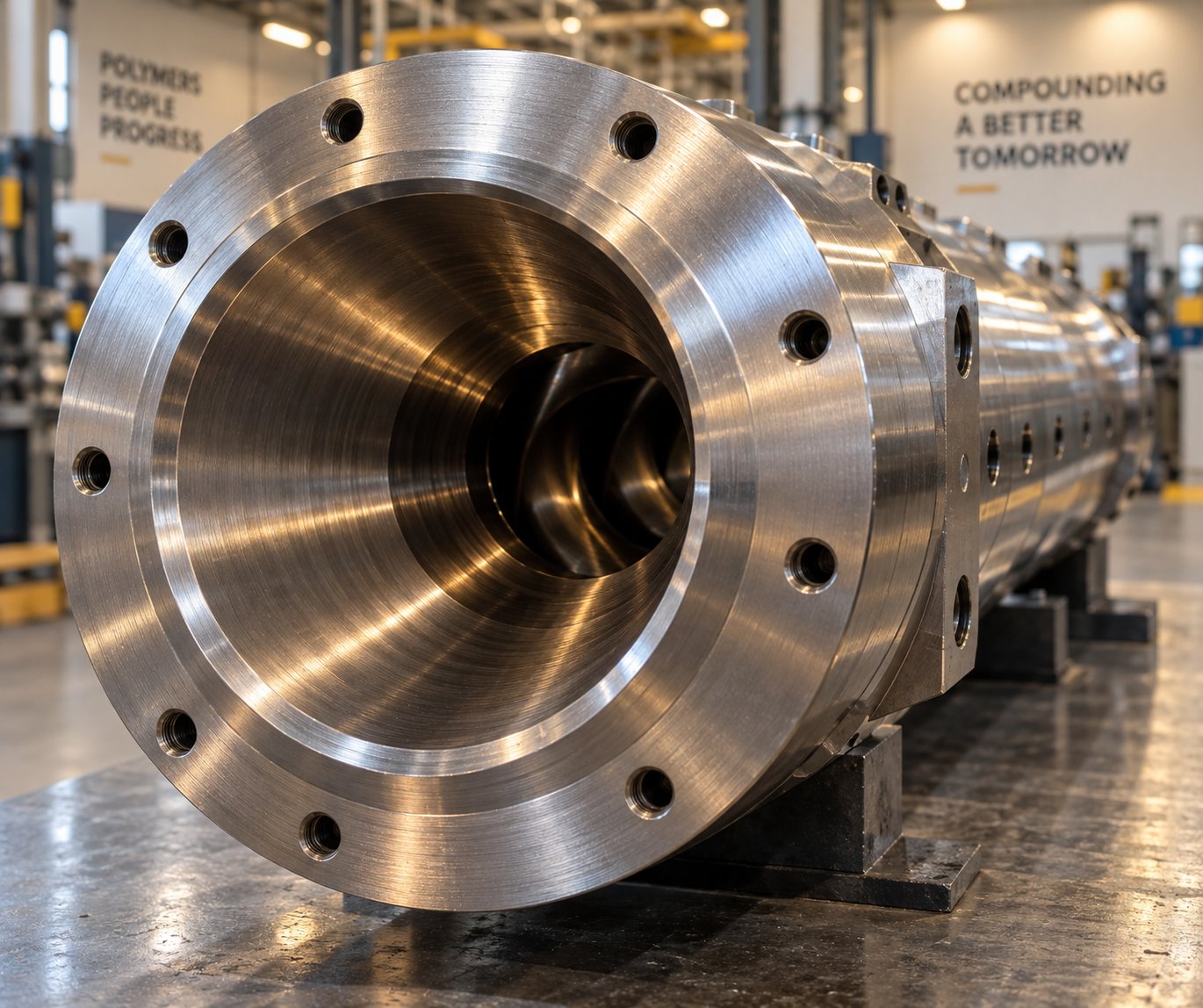
Extruder Barrel For PVC: Why PVC Destroys Barrels Faster
Oct 9, 2026
Learn why PVC destroys extruder barrels faster and how to choose the right barrel material, configuration, and maintenance strategy to maximize service life.
Read ArticleLooking for something else?
Search by material, symptom or product and jump straight to the relevant page.
These are navigation suggestions based on keyword matching — not a quotation, not a delivery commitment, and not a substitute for engineering review. Final specification is confirmed by our engineers against your drawings and processed material.
Need help with screw barrel selection?
Share your machine model, processed material and application. Our team can help with pricing and technical support.