


What a Screw Barrel Does Inside Every Plastic Machine
Every plastic product you touch — from a water bottle cap to a car bumper — began as raw pellets that had to be melted, mixed, and forced into shape. The component responsible for all three of those jobs is the screw barrel, and understanding how it works is the single fastest way to improve output quality, reduce scrap, and extend equipment life.
What Is a Screw Barrel and Why Does It Matter
A screw barrel for plastic machine applications is a matched pair consisting of a helical-flighted screw rotating inside a heated cylindrical barrel. Together, they melt, mix, and pressurize plastic resin before it reaches a die or mold. Think of it as the heart of the machine: just as a heart pumps blood at the right pressure and flow rate, the screw barrel delivers molten polymer at precisely controlled temperature, pressure, and volume. If this assembly underperforms, every downstream process — from part filling to film thickness uniformity — suffers immediately.
The barrel itself is a heavy steel cylinder, typically lined with a wear-resistant alloy to withstand years of abrasive and corrosive contact with molten plastic. The extruder screw fits inside with a remarkably tight clearance — on new equipment, just 0.005 to 0.010 in. (0.125 to 0.25 mm) between the flight tips and the barrel wall. That precision gap is what makes controlled melting and conveying possible.
How the Feed, Compression, and Metering Zones Work Together
Imagine dropping cold plastic pellets into one end of a long, heated tube and expecting perfectly uniform molten plastic to flow out the other. That transformation doesn't happen by accident — it happens across three carefully designed zones along the screw's length:
- Feed zone — The channel depth here is constant and relatively deep, designed to accept raw pellets from the hopper and begin conveying them forward. Solids conveying efficiency in this section depends heavily on the friction between pellets and the extruder feed barrel wall.
- Compression (transition) zone — The channel gradually becomes shallower, squeezing the material. This builds pressure, forces trapped air back toward the hopper, and — combined with barrel heat and internal shear — melts the resin progressively.
- Metering zone — By this point, the plastic is nearly or fully molten. The channel depth is once again constant but much shallower than the feed. This zone's job is to homogenize the melt and deliver it at consistent pressure and temperature to the die or nozzle.
Optimizing the screw barrel is the single most impactful lever a processor has for melt quality, throughput, and part consistency.
When these three zones are properly matched to the resin being processed, you'll notice stable melt pressure, uniform output, and minimal energy waste. When they're mismatched, the symptoms show up fast — surging output, unmelted particles, or degraded material.
Injection Molding vs Extrusion Applications
Although the core melting principle is identical, the screw barrel operates quite differently depending on the machine type. In an extrusion line, the screw rotates continuously, pushing a steady stream of melt through a shaping die. The goal is constant output — think pipe, film, or profile running nonstop for hours.
In an injection molding machine, the screw does double duty. It rotates to plasticize resin and build a "shot" of melt in front of the screw tip, then acts as a ram — pushing forward without rotating — to inject that shot into a closed mold. This reciprocating action places unique mechanical demands on both the screw and barrel, especially at the check valve and tip assembly.
Despite these differences, the geometry decisions that determine melt quality — channel depths, compression ratio, length-to-diameter ratio — apply to both platforms. And that geometry is exactly where the real design leverage hides.
Key Screw Geometry Parameters Every Operator Should Know
Spec sheets for extruder screws and injection screws are packed with numbers — ratios, depths, angles, diameters — and every single one of them influences how well your plastic gets melted, mixed, and delivered. The challenge is that many operators and buyers treat these figures as abstract data points rather than practical levers they can pull to improve process performance. Below is a breakdown of the dimensions that matter most, explained in terms of what they actually do on the production floor.
L/D Ratio and Its Effect on Melt Quality
The length-to-diameter ratio — commonly written as L/D — is simply the screw's flighted length divided by its outer diameter. A 90 mm extrusion screw that is 2,700 mm long has a 30:1 L/D. Sounds straightforward, but the implications for melt quality are enormous.
A longer L/D gives the resin more time inside the barrel. That means more opportunity for heat transfer, more cumulative shear, and a more thorough melt. For single-screw extrusion, typical L/D ratios fall between 20:1 and 30:1, with 24:1 and 30:1 being the most common for general-purpose and high-performance applications, respectively. Injection molding screws tend to run shorter — usually 18:1 to 24:1 — because the reciprocating screw stroke already adds effective residence time during the plasticizing phase.
Here is the trade-off you need to weigh: a higher L/D delivers better melting and mixing, but it also demands more drive torque, increases the risk of thermal degradation for heat-sensitive resins, and raises the capital cost of the screw and barrel assembly. If you're processing a simple polyolefin and chasing maximum output, a 30:1 ratio often pays for itself. If you're running PVC or another shear-sensitive polymer, a shorter L/D with careful temperature profiling may be the safer choice.
Compression Ratio, Flight Depth, and Channel Geometry
Compression ratio is defined as the ratio of the feed-zone channel depth to the metering-zone channel depth. For example, if the feed channel is 12 mm deep and the metering channel is 4 mm deep, the compression ratio is 3:1. This number tells you how aggressively the screw squeezes the material as it travels from hopper to nozzle or die.
Higher compression ratios — around 3:1 to 4:1 — work well for semi-crystalline resins like PE and PP, which absorb a large latent heat of fusion and need strong compaction to melt efficiently. Lower ratios — in the range of 1.5:1 to 2.5:1 — suit amorphous or heat-sensitive plastics such as PVC and certain styrenics, where excess shear generates damaging heat.
Flight width and helix angle are equally influential, though they receive far less attention. A wider flight land creates more shear at the barrel wall but reduces the open channel area available for material flow. The helix angle — the angle the flight makes relative to a plane perpendicular to the screw axis — controls conveying efficiency: a steeper pitch moves material faster axially but generates less shear, while a shallower pitch does the opposite. Increasing the pitch of the screw increases shear input, while decreasing channel depth or width also raises the shear applied to the material.
| Parameter | Definition | Typical Range | Why It Matters |
|---|---|---|---|
| L/D Ratio | Flighted screw length divided by outer diameter | 18:1 – 30:1 | Controls residence time, melt homogeneity, and mixing intensity |
| Compression Ratio | Feed-zone channel depth divided by metering-zone channel depth | 1.5:1 – 4:1 | Determines how aggressively resin is compacted and melted |
| Flight Depth (Feed) | Distance from flight tip to screw root in the feed section | Varies by diameter (e.g., 6 – 15 mm for 60 – 120 mm screws) | Sets solids intake capacity and initial conveying rate |
| Flight Width (Land) | Axial width of the flight at its tip | ~0.08 – 0.12 x screw diameter | Balances shear at barrel wall against open channel area |
| Helix Angle | Angle of the flight relative to a plane perpendicular to the screw axis | ~17.6° (square pitch) | Governs trade-off between forward conveyance and shear input |
How Screw Diameter Determines Output Capacity
If L/D and compression ratio shape the quality of the melt, screw diameter is the dimension that sets the quantity. Output scales roughly with the square of the diameter for drag-flow-dominated processes, which means doubling the screw size can yield roughly four times the throughput under comparable conditions. That relationship is why a jump from a 50 mm to a 100 mm extrusion screw isn't just an incremental upgrade — it's a step change in production capacity.
For buyers sizing a new machine or a replacement screw barrel, the practical guideline is to start with your target output in kilograms per hour and work backward to the diameter that can deliver it at a moderate screw speed. Running a smaller-diameter screw at very high RPM might hit the same throughput target on paper, but it pushes shear rates up dramatically. Research on shear rate in screw elements confirms that average shear rate scales directly with rotational speed and inversely with channel depth — so cranking up RPM on an undersized screw overheats shear-sensitive resins and accelerates wear on both the screw flights and barrel bore.
The smarter approach is to match diameter to volume demand, then fine-tune output by adjusting screw speed within a comfortable operating window. This preserves melt quality, extends component life, and keeps energy consumption in check — three outcomes that directly affect your cost per kilogram of finished product.
With these geometry fundamentals in hand, the next question becomes which overall screw architecture — single or twin — best fits a given application, a decision that depends on factors well beyond simple dimensions.
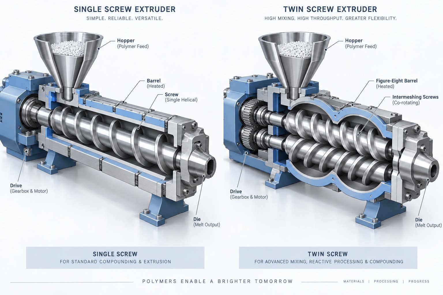
Single-Screw vs Twin-Screw Barrel Systems Compared
Screw diameter, L/D ratio, and compression ratio shape how well a screw barrel melts and delivers resin — but those parameters only tell part of the story. Before any of them can be specified, you face a more fundamental decision: should the machine use one screw or two? The answer affects everything from capital cost to mixing intensity to the range of materials you can process profitably. Yet most buyers and operators encounter only fragmented information about these two architectures. Here is a side-by-side look at both, written for the people who actually have to choose between them.
Single-Screw Barrel Systems and Where They Excel
A single-screw system is exactly what the name implies — one helical-flighted screw rotating inside one cylindrical barrel. It is the workhorse of the plastics industry and dominates the installed base worldwide. Why? Simplicity. Fewer moving parts mean lower purchase price, easier maintenance, and longer service intervals. For a plant running PE blown film, PVC pipe, or PS sheet around the clock, a well-designed single-screw extruder delivers steady, reliable output with minimal operator intervention.
Single-screw designs also excel in applications where the resin arrives pre-compounded and simply needs to be melted, conveyed, and pressurized. Profile extrusion, cast film, blown film, sheet extrusion, and general-purpose injection molding all fall comfortably within this architecture's sweet spot. The screw geometry covered in the previous section — feed, compression, and metering zones — is the foundation of virtually every single-screw machine on the market. When you match the right compression ratio and L/D to your resin, a single screw can deliver outstanding melt quality at a fraction of the cost of more complex alternatives.
That said, single-screw systems have a mixing ceiling. Because material transport depends largely on friction-driven drag flow, the distributive and dispersive mixing capability is inherently limited compared to what twin-screw configurations can achieve. For straightforward melting and forming jobs, that limitation rarely matters. For compounding, reactive processing, or handling heavily filled materials, it can become a dealbreaker.
Twin-Screw Barrel Systems for Compounding and Specialty Processing
Imagine needing to uniformly disperse 40% glass fiber into a nylon matrix, strip residual solvent from a polymer solution, or blend two immiscible polymers into a stable alloy. These tasks demand more aggressive mixing, precise control of residence time, and the ability to feed additives at multiple points along the barrel. That is where twin screw barrel systems earn their place.
Twin-screw extruders use two intermeshing screws rotating inside a figure-eight barrel bore, and they come in two principal configurations:
- Co-rotating twin screws — Both screws turn in the same direction with a fully intermeshing geometry. Material is forcibly handed from one screw to the other at the intermeshing zone, generating intense shear fields and a self-wiping action that virtually eliminates dead zones. This self-wiping behavior keeps residence time distribution narrow — critical for thermally sensitive or reactive materials. Co-rotating designs dominate compounding, polymer alloying, reactive extrusion, and nanocomposite production.
- Counter-rotating twin screws — The screws turn in opposite directions, drawing material inward at the intermeshing region. Shear stress is significantly lower than in co-rotating machines, and a calendering effect at the nip between screws provides gentle dispersive mixing. This makes counter-rotating configurations ideal for materials with poor thermal stability and low melt flow — rigid PVC pipe, sheet, and profile extrusion being the classic examples.
A defining advantage of most twin screw and barrel platforms is modularity. Barrels are typically built from individual segments that bolt together, and screws are assembled from interchangeable elements — conveying flights, kneading blocks, mixing discs, and reverse elements — on a common splined shaft. This lets process engineers reconfigure the screw profile to match a new formulation without purchasing an entirely new screw.
Devolatilization is another area where screw extruders in twin-screw form shine. Multiple vent ports can be positioned along the barrel, each isolating a vacuum zone between upstream and downstream melt seals. A practical rule of thumb: each vent can reduce volatile concentration by roughly an order of magnitude, so a triple-vented machine can take a 50%-solids feed down to below 0.1% residuals.
Choosing Between Single and Twin-Screw for Your Application
The decision ultimately rests on three variables: the resin or formulation you're processing, the mixing intensity it demands, and the production volume you need to sustain. The table below distills the comparison into the factors that matter most on the plant floor.
| Factor | Single-Screw | Twin-Screw |
|---|---|---|
| Typical Applications | Profile extrusion, blown film, sheet, general injection molding | Compounding, reactive extrusion, devolatilization, filled and reinforced resins |
| Capital Cost | Lower — simpler drive, single bore barrel, fewer components | Higher — dual gearbox, segmented barrel, modular screw elements |
| Mixing Capability | Moderate — improved with add-on mixing sections | Excellent — high shear (co-rotating) or gentle calendering (counter-rotating) |
| Maintenance Complexity | Low — one screw to inspect, straightforward clearance checks | Moderate to high — two screws, segmented barrel, more wear surfaces |
| Throughput Flexibility | Best at steady-state, fixed-output operation | Highly flexible — starve-fed operation allows independent control of feed rate and screw speed |
| Barrel Modularity | Typically one-piece barrel; limited reconfiguration | Segmented barrels allow vent ports, side feeders, and zone changes |
Here is a simple decision framework to guide your thinking:
- If your process involves melting a single, pre-compounded resin and forming it into a final shape — a single-screw system almost certainly meets your needs at the lowest total cost.
- If you need to blend, compound, devolatilize, or reactively modify the material — a co-rotating twin-screw extruder provides the mixing intensity and process flexibility that single-screw designs simply cannot match.
- If you process rigid PVC or other thermally fragile materials that demand low-shear conditions — a counter-rotating twin-screw configuration offers the gentle, controlled processing these resins require.
Many facilities run both architectures side by side: twin-screw compounding lines prepare the formulation, and single-screw extruders or injection machines convert those pellets into finished products. The key is recognizing which architecture serves each step most efficiently.
Of course, choosing between single and twin-screw is only the starting point. Within each architecture, a range of specialty configurations — barrier flights, mixing elements, grooved feed zones — can dramatically shift performance for specific resins and applications.
Specialty Screw Barrel Configurations Beyond General Purpose
Standard three-zone screw designs handle a wide range of everyday plastics processing, but they leave performance on the table in demanding applications. When you're chasing higher throughput on a screw plastic extruder, trying to eliminate unmelted particles in a thick-wall injection molded part, or processing moisture-sensitive resins without a separate drying step, the general-purpose screw simply runs out of headroom. That's where specialty configurations come in — barrier flights, dedicated mixing elements, grooved feed sections, and vented extrusion barrels. Each targets a specific process limitation, and knowing when to specify one can mean the difference between a marginal operation and a highly efficient production line.
Barrier Screws and Improved Melting Efficiency
Picture what happens inside a conventional screw as pellets begin to melt. A thin film of molten polymer forms against the hot barrel wall and gets scraped into a growing melt pool on one side of the channel. The remaining solid bed — a compacted mass of partially heated pellets — rides along the other side. In theory, the solid bed shrinks steadily as it travels down the screw. In practice, the bed often fractures midway through the transition zone. Those broken chunks of unmelted resin tumble into the melt pool, and because plastics are poor conductors of heat, they can survive all the way to the metering zone — or worse, into the die or mold.
A barrier screw tackles this problem head-on by adding a secondary flight — the barrier flight — that physically separates the solid bed from the melt pool. The barrier flight sits slightly lower than the primary flight, creating a small clearance gap above it. Molten polymer can flow over this gap into a dedicated melt channel, but solid material cannot. The result is two distinct channels running side by side: one containing solids that continue to melt, and one accumulating clean melt. As extrusion expert Jim Frankland explains, this design ensures that solids are completely melted by the time they reach the metering section, producing a more thermally homogeneous melt without needing a separate mixing section downstream.
Barrier screws deliver the greatest benefit in high-throughput extrusion and injection molding of semi-crystalline polymers like PE and PP. Crystalline resins don't soften gradually the way amorphous materials do — they hold their rigid structure right up to the melting point, then transition sharply. That makes them especially prone to solid-bed breakup in conventional designs. A well-engineered barrier flight keeps the solid bed intact and under controlled compression, accelerating the melting rate and producing a narrower melt-temperature distribution at the screw tip.
There is a design caution worth noting, however. If the barrier section is made too long or the compression too gradual, broken solid pieces can collect at the downstream end of the solids channel and create extreme localized pressure. Frankland documented a case on an 8-inch barrier screw where approximately 350,000 lb of force was generated at the plug point — enough to bend the screw shaft by 0.100 in. and wear the flights down to the root diameter. The takeaway: barrier screws are powerful tools, but the transition geometry must be carefully matched to the melting rate of the specific resin.
Mixing Sections, Distributive and Dispersive Elements
Even with a perfect melt free of solid particles, the polymer may still lack uniformity. Color concentrate could be unevenly distributed. Additive agglomerates might survive the melting process intact. Temperature gradients between the core and the barrel-side melt can persist into the final product. Mixing sections address all three issues, and understanding the two fundamental types of mixing helps you pick the right element for the job.
Dispersive mixing applies high shear stress to break apart agglomerates, gels, and undissolved additive clusters. Imagine forcing the melt through a very narrow gap between two surfaces — the intense shear in that gap tears particle clusters apart. Distributive mixing, on the other hand, repeatedly divides and recombines the melt stream, spreading all components uniformly across the cross-section without necessarily applying high stress. Think of folding dough over and over — each fold improves spatial uniformity.
Most real-world applications need some combination of both. As Frankland notes in his overview of single-screw mixing, a worn screw with excessive flight clearance actually mixes quite well because polymer leaking over the flights experiences both high shear (dispersive) and continuous blending into adjacent channels (distributive). Of course, worn screws also lose output — so purpose-built mixing elements replicate that effect without sacrificing throughput.
Here are the most commonly used mixer types on single-screw extruder and injection screw platforms:
- Maddock (fluted) mixer — A series of alternating inlet and outlet flutes separated by a narrow barrier clearance. Melt enters the inlet flutes and must pass over the high-shear barrier to reach the outlet flutes, delivering strong dispersive mixing with moderate distributive action. This is the most widely used mixer in single-screw extrusion.
- Saxton mixer — Features multiple, staggered flight channels that repeatedly split and recombine the melt stream. It provides excellent distributive mixing with comparatively low shear stress, making it a good choice for heat-sensitive or pre-dispersed materials.
- Egan (undercut-flight) mixer — All flights are undercut so that melt flows both over and around the elements, creating high levels of both dispersive and distributive mixing simultaneously. It is well suited for applications that demand thorough blending of colorants or additives.
- Pineapple mixer — Named for its studded surface, this element repeatedly redirects and recombines flow, providing primarily distributive mixing. It is often used near the screw tip in injection molding screws to homogenize the shot just before injection.
- Blister ring — A simple cylindrical ring that forces melt through a narrow annular gap. It acts as a dam to trap unmelted solids while providing some dispersive mixing. Often used as a low-cost insurance element ahead of the metering zone.
Selecting the right mixing element — or combination of elements — depends on what defect you're trying to eliminate. Gels and undispersed pigment call for a dispersive-dominant design like the Maddock. Uneven color distribution with no agglomerate issues points toward a distributive mixer like the Saxton. Many screw designs incorporate both types in series for the best overall melt quality.
Grooved Feed Barrels and Vented Barrel Designs
Not all specialty configurations live on the screw itself. Some of the most impactful performance upgrades happen in the extrusion barrels — specifically at the feed throat and along the barrel's length.
A grooved feed barrel replaces the smooth bore in the feed zone with a series of longitudinal grooves machined into the barrel wall, typically spanning three to four diameters past the feed opening. These grooves grip the resin pellets mechanically, preventing them from spinning in place with the screw. The effect on solids conveying is dramatic, especially with slippery polyolefins.
A grooved feed barrel can increase output by 20-40 percent compared to a smooth-bore barrel when processing HDPE — but it demands higher drive torque and careful thermal management.
That output gain comes with requirements, though. Grooved feed sections must be intensively water-cooled to prevent pellets from melting inside the grooves, which would destroy the mechanical grip and cause bridging. Pressures at the downstream end of the grooved section can reach 15,000-20,000 psi, so the equipment must be designed to handle loads up to 30,000 psi. The screw paired with a grooved feed also needs shallower feed-zone channels than a smooth-bore design — typically around 0.25-0.4 in. deep on a 3.5-inch screw extruder, compared to 0.6-0.7 in. for the same diameter smooth bore. This keeps forward force high in the grooves and ensures adequate compression entering the heated barrel.
Polyolefin processors running dedicated high-output lines — PE pipe, HDPE blown film, PP sheet — benefit the most from grooved feeds. Resins with higher melting points, like nylon or polycarbonate, generally require the grooves to be heated rather than cooled, which reduces feeding efficiency and offsets some of the output advantage. Likewise, operations handling a wide variety of resins or high percentages of low-bulk-density regrind typically fare better with smooth-bore feed sections, where deeper channels are less sensitive to particle size variation.
Vented barrel designs serve a completely different purpose: removing moisture, trapped air, or volatile byproducts from the melt without a separate upstream drying step. A vent port — an opening in the barrel wall connected to vacuum — is positioned at a point where the screw geometry creates a decompression zone. In this low-pressure region, the melt is only partially filling the channel, allowing gases and volatiles to escape through the vent rather than being carried into the final product.
The screw design for a vented barrel is critical. It typically features a two-stage profile: the first stage melts and compresses the resin, then a sudden increase in channel depth drops the pressure to near atmospheric, exposing the melt surface at the vent. The second stage recompresses and meters the melt to the die. If the first stage overfeeds relative to the second stage's pumping capacity, melt will flood the vent — a messy and potentially dangerous condition. That balance is especially important in grooved-feed extruders, where the first-stage conveying rate can easily exceed the second stage's capacity.
Vented barrels are most commonly used for processing hygroscopic resins like PET and nylon, for devolatilizing recycled materials, and for specialty applications such as reactive extrusion where byproduct removal is part of the chemistry. Each vent port, when properly designed, can reduce volatile content by roughly an order of magnitude, making multi-vent configurations capable of achieving very low residual levels.
These specialty configurations — barrier flights, mixing elements, grooved feeds, and vented barrels — represent the tools available to fine-tune a screw barrel for plastic machine performance well beyond what a standard three-zone design can deliver. The real art, though, lies in knowing which tool to apply for which resin — a topic that demands its own detailed treatment.
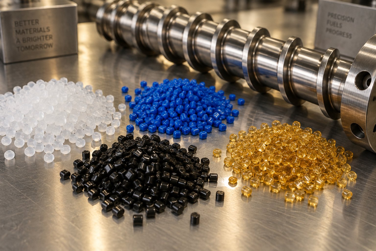
Matching Screw Barrel Design to Your Plastic Resin
Barrier flights, mixing elements, grooved feeds, vented barrels — each one solves a specific processing limitation. But here is the question that ties them all together: which combination belongs on your machine, running your resin? A plastic extruder screw optimized for HDPE will destroy PVC within minutes. Injection molding screws and barrels perfectly suited for polycarbonate will underperform badly on nylon if the barrel lacks venting. Resin chemistry dictates screw geometry, barrel metallurgy, and thermal profile more than any other single variable, yet most technical references treat screw design and material selection as separate topics. Below is the practical compatibility guide that connects them.
Commodity Resins — PE, PP, PS, and PVC
Commodity resins account for the vast majority of global plastics processing volume, and each one places distinct demands on the screw barrel assembly. The differences are rooted in how these polymers behave as they transition from solid pellets to flowing melt.
Polyolefins — polyethylene and polypropylene — are semi-crystalline. They hold a rigid solid structure right up to a sharp melting point, then drop rapidly in viscosity. That sharp phase change makes them especially prone to solid-bed breakup in conventional screws, which is why barrier screw designs and grooved feed barrels deliver the biggest gains with PE and PP. A relatively high compression ratio (between 2.5:1 and 4:1) provides the compaction force needed to drive the solid bed against the barrel wall where melting occurs. Because polyolefins are thermally stable and non-corrosive, a standard nitrided barrel or bimetallic lining is usually sufficient for long service life.
Polystyrene sits on the opposite end of the crystallinity spectrum — it is fully amorphous. There is no sharp melting point, just a gradual softening as temperature increases. PS melts relatively easily and tolerates moderate shear, so a general-purpose screw with a compression ratio around 2.0:1 to 3.0:1 handles it well. The main processing caution is avoiding excessive melt temperature, which causes thermal degradation and off-gassing. Standard nitrided barrels work fine for unfilled PS grades.
PVC is the outlier. It begins to degrade and release hydrochloric acid (HCl) at temperatures not far above its processing window. That acid attacks standard barrel steel aggressively, which is why PVC processing demands corrosion-resistant barrel linings — typically nickel-based alloys or bimetallic liners with high chromium content. Screw design for PVC must minimize shear heating: low compression ratios (1.5:1 to 2.0:1), shallow flight depths, and smooth transitions are essential. Most rigid PVC processors use counter-rotating twin-screw extruders specifically because they provide gentle, low-shear conveying. On single-screw machines, a dedicated PVC screw with a very gradual compression zone and no aggressive mixing elements is standard practice.
| Resin | Recommended Compression Ratio | Barrel Lining | Key Processing Consideration |
|---|---|---|---|
| PE (HDPE/LDPE) | 2.5:1 – 4.0:1 | Nitrided or standard bimetallic | Benefits from barrier screws and grooved feed zones; sharp crystalline melt transition requires strong compaction |
| PP | 2.5:1 – 3.5:1 | Nitrided or standard bimetallic | Similar to PE; slightly narrower processing window — avoid excessive melt temperature to prevent oxidative degradation |
| PS | 2.0:1 – 3.0:1 | Standard nitrided | Amorphous, melts easily; main risk is thermal degradation at high melt temperatures |
| PVC | 1.5:1 – 2.0:1 | Corrosion-resistant (Ni-alloy or high-Cr bimetallic) | HCl off-gassing demands corrosion-resistant metallurgy; low-shear screw design is critical to avoid degradation |
Engineering Resins — PA, PC, ABS, and PET
Step up from commodity resins to engineering polymers, and the screw barrel requirements shift dramatically. These materials command higher prices, tighter dimensional tolerances, and stricter quality expectations — all of which make screw and barrel selection more consequential.
Polyamide (nylon) and PET share a critical characteristic: they are hygroscopic. Both absorb atmospheric moisture readily, and that moisture causes hydrolytic degradation during processing — chain scission that destroys mechanical properties and produces visible defects like splay, bubbles, and haze. The traditional countermeasure is thorough pre-drying in a desiccant dryer to bring moisture content below 0.02% for nylon and below 0.005% for PET. However, vented barrel designs offer an alternative or supplementary approach, removing moisture directly from the melt through vacuum ports positioned at decompression zones along the screw. As discussed in the previous chapter, each vent stage can reduce volatile content by roughly an order of magnitude, making vented processing especially attractive for recycled PET flake where moisture levels are difficult to control consistently.
Nylon's semi-crystalline nature calls for a moderately high compression ratio — typically 3.0:1 to 3.5:1 — and benefits from a barrier screw design for the same reasons polyolefins do. Barrel linings should resist both the abrasion from glass-fiber-filled grades and the mild corrosive attack of moisture-related byproducts. For glass-filled nylons, a bimetallic barrel with a tungsten carbide or boron-alloy liner extends service life substantially compared to a nitrided-only bore.
Polycarbonate presents a different set of challenges. Its melt viscosity is among the highest of any common thermoplastic, requiring significant energy input to plasticize and considerable barrel pressure to push through a die or fill a mold cavity. Injection molding screws for PC benefit from higher L/D ratios — 22:1 to 24:1 is common — to provide enough residence time for complete melting without resorting to extreme barrel temperatures that risk thermal degradation. Compression ratios in the range of 2.0:1 to 2.5:1 suit PC's amorphous character, and the drive system must deliver high torque at moderate screw speeds. Barrel metallurgy is less demanding than for PVC or filled nylons, since unfilled PC is neither abrasive nor highly corrosive. Standard nitrided or bimetallic linings perform well.
ABS — a blend of acrylonitrile, butadiene, and styrene — is amorphous and processes in a moderately forgiving window. A compression ratio of 2.0:1 to 2.5:1 and an L/D of 20:1 to 24:1 handle most ABS grades effectively. The key consideration is avoiding excessive shear, which can degrade the butadiene rubber phase and impair impact strength. For injection molding screws and barrels running ABS, a general-purpose screw with a gentle compression gradient and a distributive mixing section near the tip produces the most consistent parts. Flame-retardant ABS grades introduce corrosive byproducts during processing, making corrosion-resistant barrel liners advisable for extended production runs.
PET processing, particularly for preform injection molding, adds one more wrinkle: acetaldehyde (AA) generation. AA is a thermal degradation byproduct that imparts an off-taste to bottled beverages. Minimizing AA requires short residence times, low melt temperatures, and screws designed to avoid dead spots where material can stagnate and cook. Specialized PET injection molding screws feature shallow, high-efficiency metering zones and streamlined check-valve assemblies to reduce hold-up volume. Some processors specify bimetallic barrels even for unfilled PET simply to maintain tight bore tolerances over millions of cycles, since any clearance increase lengthens residence time and raises AA levels.
High-Performance Polymers — PEEK, PEI, and Filled Compounds
When you encounter resins like PEEK (polyetheretherketone) and PEI (polyetherimide), you've entered processing territory where standard equipment simply cannot survive. PEEK melts at approximately 343 degrees Celsius (650 degrees Fahrenheit), and PEI's processing temperature exceeds 350 degrees Celsius. At these temperatures, conventional barrel heaters may not deliver sufficient energy density, standard thermocouple placements may read inaccurately due to steep thermal gradients, and ordinary tool-steel screws soften or lose hardness.
A plastic extruder screw designed for PEEK or PEI typically uses a high-alloy tool steel — often PM (powder metallurgy) grades with enhanced hot hardness — and may receive a specialized hard-chrome or nickel-alloy coating for additional protection. Barrel linings must withstand sustained high temperatures without losing wear resistance. Bimetallic barrels with nickel-boron or cobalt-based alloy linings are standard for these applications, since conventional nitrided barrels lose their case hardness above 500 degrees Celsius and become vulnerable to rapid erosion.
Barrel heating capacity itself often needs upgrading. Standard ceramic band heaters may struggle to reach and maintain temperatures above 400 degrees Celsius uniformly, so many high-performance processing lines switch to mica band heaters with higher watt density or cast aluminum heater assemblies that provide more consistent heat transfer along the barrel length. Some processors also insulate the barrel heavily to reduce energy loss and improve zone-to-zone temperature control at these extreme setpoints.
Filled and reinforced compounds — whether the base resin is nylon, polypropylene, PEEK, or anything in between — introduce the additional challenge of abrasive wear. Glass fibers, carbon fibers, mineral fillers like talc and calcium carbonate, and ceramic microspheres all act like fine sandpaper against the screw flights and barrel bore. The wear rate scales with filler loading, filler hardness, and processing throughput. A 40% glass-filled nylon compound can wear through a standard nitrided barrel bore in a fraction of the time an unfilled grade would take.
The countermeasures are straightforward but essential:
- Bimetallic barrel linings — Centrifugally cast alloys containing tungsten carbide, boron carbide, or vanadium carbide particles embedded in a nickel or iron matrix. These linings offer three to five times the abrasion resistance of nitrided steel and are considered standard for any barrel running filled compounds at volume.
- Hard-faced screw flights — Welded overlays of cobalt-based alloys (such as Stellite) or nickel-tungsten carbide composites applied to the flight tips — the highest-wear area on the screw. Hard-facing extends flight life and maintains the tight barrel-to-flight clearance that preserves conveying efficiency and melt quality.
- Tool-steel or PM-steel screw bodies — For severely abrasive or corrosive applications, upgrading the entire screw from 4140 or 4340 steel to a powder-metallurgy tool steel like CPM 9V or CPM 10V provides enhanced wear resistance throughout, not just at the flight tips.
Investing in these materials adds cost upfront, but the payback period is often measured in months rather than years. A bimetallic barrel and hard-faced screw running a 30% glass-filled PA6 compound may last two to three times longer than a standard nitrided set, avoiding the production downtime, scrap, and lost output that accompany premature wear.
Matching screw design and barrel metallurgy to your specific resin is the foundation of consistent, efficient processing. Yet even a perfectly specified assembly will underperform if the thermal environment surrounding it — the barrel's heating and cooling zone configuration — is not managed with equal care.
Barrel Heating and Cooling Zone Design Explained
You could install the perfect screw — ideal compression ratio, flawless barrier geometry, premium metallurgy — and still produce inconsistent melt if the barrel's thermal zones are poorly configured. The reason is simple: the screw determines how energy is applied to the resin, but the extruder barrel supplies a significant portion of what energy is available. Temperature zones that are set too high cook the polymer. Zones set too low leave unmelted solids in the output. And a feed throat without proper cooling can shut the entire machine down in minutes. Thermal management of the barrel is arguably the least understood — and most frequently misadjusted — variable in plastics processing.
How Barrel Heating Zones Influence Melt Temperature
Most extrusion and injection molding barrel assemblies are divided into multiple independently controlled heating zones, typically four to six on a standard machine and sometimes ten or more on large-diameter or high-L/D systems. Each zone has its own set of heaters — usually ceramic or mica band heaters wrapped around the barrel exterior, though cartridge heaters are common in smaller-diameter barrels — paired with a dedicated thermocouple embedded in the barrel wall. A PID controller reads each thermocouple and adjusts heater output to hold the zone at its setpoint.
Here is where it gets interesting. The temperature you set on the controller is not the temperature the melt actually reaches. As extrusion training specialists point out, the displayed zone temperature depends heavily on where the thermocouple sits within the barrel wall — closer to the bore reads hotter, closer to the outer surface reads cooler — and the real melt temperature is often significantly higher than any of the barrel setpoints because viscous shear heating inside the screw channel adds substantial energy that thermocouples can't directly measure.
That gap between setpoint and actual melt temperature is why zone profile selection matters so much. Three common profile strategies cover the vast majority of applications:
- Rising profile — Temperature increases progressively from the feed end to the die or nozzle. This is the default starting point for most semi-crystalline resins like PE, PP, and nylon. It ensures that solids in the early zones aren't overheated before compression can build adequate pressure, while the front zones supply enough energy to finish melting and homogenize the melt.
- Flat (constant) profile — All zones from zone one onward are set to the same target processing temperature. This approach suits materials that melt easily and tolerate uniform heat input, such as certain grades of PS or pre-compounded masterbatch.
- Hump (peaked) profile — Temperatures rise through the middle zones to a peak above the target melt temperature, then drop back down in the metering and nozzle zones. This profile is used when the screw needs extra thermal input in the transition region to accelerate melting, but the processor wants to pull heat back out near the exit to avoid thermal degradation. Rigid PVC is the classic example — processors often use a flat or even descending profile to keep the melt well below the degradation threshold, relying primarily on shear rather than conductive barrel heat to plasticize the material.
Setting the initial temperature profile involves a few material-specific anchors. The feed zone stays well below the resin's softening point — typically 20-60 degrees Celsius for standard thermoplastics, or 60-95 degrees Celsius when higher throughput or lower drive torque is desired. The final zone (die or nozzle) is set near the manufacturer's recommended processing temperature. For semi-crystalline materials, that is often 50-75 degrees Celsius above the crystalline melting point; for amorphous resins, roughly 100 degrees Celsius above the glass transition temperature. The intermediate zones are then interpolated evenly between these two anchor points, following whichever profile shape suits the resin and screw design.
The Role of Barrel Cooling in Feed Zone and Process Control
Heating gets all the attention, but cooling is equally critical — especially at the feed throat, where improper thermal management causes one of the most disruptive production problems: bridging.
The feed throat is the transition between the hopper and the first full flight of the screw. Its job is straightforward: provide a clear, free-flowing path for pellets into the screw channel while allowing trapped air and volatiles to vent back up through the hopper. If the feed throat runs too hot, pellets begin to soften and stick together before they enter the screw flights. This creates a Type 1 bridge — a clump of loosely fused granules that blocks material flow. On an injection molding barrel, roughly 80% of bridging-related downtime traces back to feed-throat temperature issues, according to injection molding consultant John Bozzelli.
Water-cooled feed throats are standard on virtually all modern extruders and injection machines. Circulating coolant through channels machined into the feed-throat casting keeps the metal temperature low enough to prevent premature pellet softening. In grooved feed barrels — where mechanical grip on the pellets is essential for the high-output conveying effect — intensive cooling is even more critical. If pellets melt inside the grooves, the mechanical friction advantage disappears instantly, and output collapses.
Air cooling plays a supporting role farther down the barrel. Many extrusion barrel configurations include blower-cooled zones in the transition region, allowing the controller to remove excess heat when viscous shear heating pushes the melt temperature above the setpoint. This is the heart of the thermal balancing act: at any point along the screw, the melt temperature is the result of conductive heat from the barrel wall plus viscous shear heat generated by screw rotation minus any cooling applied. Adjusting barrel temperature alone — without considering screw speed and screw geometry — gives you only one-third of the picture.
Imagine running a high-speed extrusion line on HDPE. The screw's shear input alone might generate enough heat to fully melt the resin, meaning the barrel heaters in the front zones may never turn on at all. In that situation, the barrel's cooling system is what actually controls melt temperature. If the cooling capacity is insufficient, the melt overheats, viscosity drops, and output becomes unstable. This is why high-output grooved-feed extruders are designed with robust cooling infrastructure from the start — it isn't optional equipment.
Diagnosing Temperature-Related Process Problems
When melt quality deteriorates or output becomes erratic, barrel zone temperatures are often the first thing operators adjust — and the last thing they adjust correctly. The challenge is that temperature-related symptoms can look identical to screw-wear or material-related problems. A systematic approach saves time and avoids chasing the wrong root cause.
Here are common symptoms and the barrel-zone issues most likely behind them:
- Melt temperature running too high — Reduce rear-zone setpoints to shift more melting energy toward the transition and metering sections, or reduce screw speed to lower shear heat input. On shear-dominated processes, the barrel heaters may already be off and the problem is purely mechanical — the screw is simply generating too much frictional energy at the current RPM.
- Unmelted particles or gels in the output — Increase transition-zone temperature to supply more conductive energy where solid-bed melting is most active. Also check for worn screw flights — excessive flight clearance reduces shear input and allows unmelted material to bypass the compression zone. A non-optimal temperature profile in the first few zones is one of the most common — and most correctable — causes of melt inhomogeneity.
- Degradation, discoloration, or black specks — Check for dead spots in the barrel where material can stagnate: around thermocouples seated too deeply, at joints between barrel segments, or in oversized adapter bores. Excessive residence time in hot zones cooks sensitive polymers. Also verify that no single zone is running far above the resin's recommended processing ceiling.
- Surging output or fluctuating melt pressure — A mismatch between the feed-zone temperature and the screw's solids-conveying design often causes periodic pressure swings. If the feed zone is too warm, pellets partially melt and slip instead of being gripped and pushed forward. If it is too cold, volatiles may condense and interfere with consistent feeding.
- Bridging at the feed throat — On an injection molding barrel, distinguish between Type 1 bridges (granules stuck together from excessive feed-throat heat) and Type 2 bridges (a solid clump of mostly melted plastic caused by backflow from a worn check valve, screw, or barrel). Lowering feed-throat temperature only fixes Type 1. Type 2 requires identifying and replacing the worn component.
The barrel provides heat input, but the screw determines how that energy is applied — optimizing one without the other is incomplete.
Temperature optimization is rarely a one-time event. Changes in raw material lot, ambient plant temperature, throughput rate, or accumulated screw wear all shift the thermal balance. The most consistent processors treat their zone profiles as living settings — monitored continuously and adjusted methodically whenever conditions change. That discipline, combined with a solid understanding of how the screw and barrel interact thermally, is what separates stable, high-quality production from constant firefighting on the shop floor.
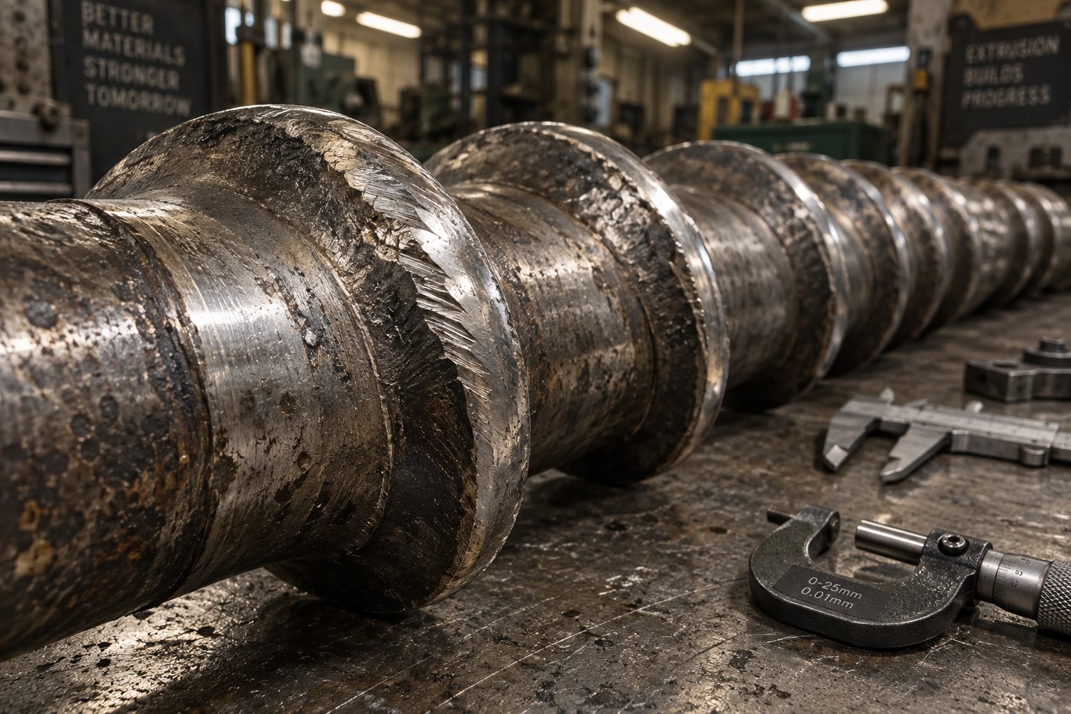
Troubleshooting Common Screw Barrel Problems
You have dialed in your barrel zone temperatures, verified the screw geometry matches your resin, and production is humming along — until it isn't. A part comes off the line with visible gels. The die pressure gauge starts swinging. Scrap bins fill faster than they should. The frustrating reality of extruder screw barrel issues is that symptoms on the production floor rarely point directly at their root cause. Melt defects, output instability, and premature component wear all overlap in how they present, which leads operators to chase the wrong fix. Below is a practical, operator-focused guide to diagnosing the most common screw and barrel problems — and acting on them before they escalate.
Output Surging and Inconsistent Melt Delivery
Surging — that rhythmic rise and fall in die pressure or extrudate thickness — is one of the most common and most misunderstood problems in plastics processing. You'll see it as periodic weight variation in injection molded parts, pulsating film thickness on a blown-film line, or a melt-pressure trace that cycles every few seconds to minutes.
What's actually happening inside the barrel? In most cases, the solid bed is breaking up prematurely in the transition zone. Chunks of unmelted resin break free, tumble into the melt pool, and temporarily disrupt the steady flow of material toward the metering section. Once the chunk melts or passes through, flow stabilizes briefly — then the cycle repeats. MD Plastics notes that this pattern of melting jumping forward and back along the screw is a primary driver of cyclic output at the die.
Worn screw flights compound the problem significantly. As flight-tip clearance increases, more material leaks backward over the flights instead of being pushed forward. This reduces net conveying efficiency and makes the output more sensitive to small changes in feed rate, screw speed, or barrel temperature. Improper temperature profiles — particularly a feed zone running too warm — also cause pellets to partially melt and slip rather than being gripped and transported consistently.
When surging appears, work through these diagnostic steps:
- Check screw flight clearance — Measure the gap between the flight OD and barrel ID at multiple points. If diametral clearance exceeds roughly twice the original specification, conveying efficiency has degraded enough to cause instability.
- Verify thermocouple accuracy — A drifting thermocouple in the feed or transition zone can silently shift the temperature profile, altering where melting begins.
- Evaluate screw design suitability — A screw with an overly aggressive compression ratio for the resin being run can cause solid-bed breakup. Conversely, too gentle a compression may fail to build enough pressure for stable metering.
Poor Mixing, Gels, and Unmelted Particles
Finding gels, color streaks, or visible unmelted specks in your product? These defects point to insufficient homogenization somewhere along the melt path. The extruder screws and barrels may be functioning mechanically, but the melt they deliver lacks uniformity — and the causes usually trace back to geometry or wear.
An insufficient L/D ratio is one of the most overlooked culprits. When the screw simply doesn't provide enough residence time for the resin to fully melt and mix, no amount of barrel temperature adjustment will compensate. Similarly, a wrong compression ratio — too low for a crystalline resin or too high for a shear-sensitive amorphous material — disrupts the orderly melting progression that produces clean melt.
The absence of dedicated mixing elements is another frequent cause, especially on older machines still running original general-purpose screws. Without a Maddock mixer, Saxton section, or comparable dispersive-distributive element, the screw relies entirely on drag flow to blend the melt. That works adequately for simple, unfilled resins but falls short when colorants, additives, or recycled content enter the picture.
Wear amplifies every mixing deficiency over time. As extrusion troubleshooting experts explain, worn screw flights reduce the shear input available to break down agglomerates and homogenize temperature gradients. The melt may look fully molten at the die exit, yet contain pockets of poorly mixed material that produce gels or weak spots in the finished part. Regular screw inspection — not just visual, but dimensional measurement of flight OD — catches this degradation before it reaches the product.
Accelerated Wear, Scoring, and Material Degradation
Every screw and barrel wears over time, but accelerated wear signals that something in the process, material, or equipment setup is actively shortening component life. Three distinct wear mechanisms dominate, and identifying which one is active determines the correct response.
Abrasive wear is the most common form in extruder screw barrel assemblies processing filled resins. Glass fibers, mineral fillers, and pigments act like fine sandpaper against flight tips and barrel bore. Xtrutech's wear analysis confirms that the level of abrasion depends on materials of construction, screw speed, throughput, and the specific formulation being processed — making it throughput-dependent rather than time-dependent. Rounded, polished flight edges are the telltale signature.
Corrosive wear shows up as pitting or dimpling on metal surfaces. PVC's HCl off-gassing and halogenated flame-retardant compounds are the primary offenders. This damage may not be immediately visible during routine inspections but becomes apparent under magnification or when bore-gauge measurements reveal localized enlargement in the barrel.
Adhesive wear occurs when metal-to-metal contact happens — screw flights rubbing directly against the barrel wall. This typically follows excessive abrasive or corrosive wear that has opened clearances beyond the point where the melt film can keep the screw centered. Score marks on the barrel wall and flattened flight ODs are definitive indicators. In twin-screw systems, adhesive wear also results from screw deflection when the shafts lose support, particularly during idle rotation between production runs.
The table below consolidates the most common symptoms, their probable screw-and-barrel root causes, and the corrective actions that address them. Use it as a quick-reference guide during your next production issue.
| Symptom | Likely Root Cause | Corrective Action |
|---|---|---|
| Cyclic surging in output or melt pressure | Solid-bed breakup from worn flights, mismatched compression ratio, or improper feed-zone temperature | Measure flight clearance; adjust feed-zone temperature; evaluate screw design for resin compatibility |
| Unmelted particles or gels in finished product | Insufficient L/D ratio, worn compression zone reducing shear input, or absence of mixing elements | Add or upgrade mixing section; inspect screw for wear; consider higher L/D replacement screw |
| Rapid flight-tip erosion and barrel bore enlargement | Abrasive wear from glass-fiber or mineral-filled compounds | Upgrade to bimetallic barrel lining and hard-faced screw flights; reduce screw speed if possible |
| Pitting or dimpling on barrel bore and screw surfaces | Corrosive attack from PVC, flame-retardant additives, or moisture-related acidic byproducts | Switch to corrosion-resistant barrel alloy (Ni-based or high-Cr bimetallic); verify resin drying procedures |
| Score marks on barrel wall and flattened screw flight ODs | Adhesive (metal-to-metal) wear from excessive clearance allowing screw deflection | Replace worn screw and barrel as a matched set; investigate root cause of original clearance loss |
| Discoloration, black specks, or burnt odor | Material degradation from dead spots, excessive residence time, or overheated barrel zones | Check for stagnation points at adapters and barrel joints; reduce rear-zone temperatures; verify screw speed is not too low |
| Gradual decline in output rate at constant screw speed | Progressive flight wear reducing conveying efficiency and compression | Measure screw OD at feed, transition, and metering zones; schedule rebuild or replacement when clearance exceeds 2x original spec |
A pattern worth noticing in this table: most corrective actions begin with measurement, not adjustment. Operators who reach for the temperature controller first are often treating symptoms rather than causes. The fastest path to resolution almost always runs through a dimensional check of the screw and barrel — confirming whether the hardware can still deliver what the process demands. And that raises a bigger question: how do you systematically measure wear, interpret what you find, and decide whether a screw barrel needs refurbishment or outright replacement?
Screw Barrel Maintenance and Wear Diagnosis
That troubleshooting table from the previous section reveals an important pattern: nearly every corrective action starts with measuring the screw and barrel — not tweaking a setpoint. Yet most plants treat dimensional inspection as something that only happens after a production crisis forces a teardown. The reality is that proactive measurement, pattern recognition, and informed rebuild-or-replace decisions are what separate facilities with predictable maintenance budgets from those constantly reacting to unplanned downtime. Here is the practical framework that production managers and maintenance technicians need to manage screw barrel lifecycle costs effectively.
How to Measure Screw and Barrel Wear
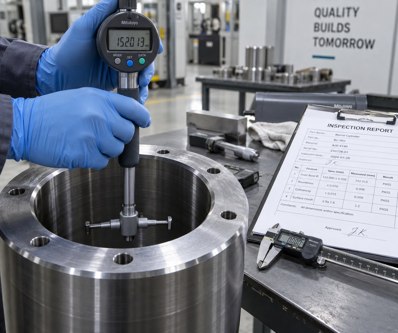
Sounds complex? The tools are surprisingly simple — what matters is consistency and documentation. You need two instruments: a calibrated bore gauge for measuring the barrel's internal diameter, and an outside micrometer for measuring the screw's outer diameter at the flight tips.
Start with the screw. Adams Engineers recommends removing all residual resin and placing the screw on a clean, flat surface — a granite inspection table is ideal for simultaneously checking straightness by rolling the screw and looking for bowing. Use a parallel test bar spanning two flights to get an accurate OD reading with the micrometer. Measure at multiple points along the screw's length: at least one reading in each functional zone (feed, transition, metering) and at any mixing section or barrier flight. Record every value and compare it to the original specification or the last inspection.
For extruder barrels, insert a bore gauge as far down each end as the extension rods allow and take readings at several axial positions. Electronic bore gauges can transmit readings directly to a computer for logging, but a well-maintained analog gauge works perfectly when paired with disciplined record-keeping. Always measure in at least two orientations — 0 degrees and 90 degrees — at each axial station to detect ovality, which indicates uneven wear from screw deflection.
What clearance triggers action? The critical number is diametral clearance — the difference between the barrel ID and the screw flight OD. On new equipment, this gap is extremely tight. Industry data shows that a 50 mm diameter screw should have a minimum gap of approximately 0.10 mm, while a larger 152 mm screw sits around 0.30 mm. As a general rule, when the diametral clearance exceeds roughly twice the original specification, performance degrades measurably — output drops, melt quality deteriorates, and energy consumption climbs. A 10% decrease in injection screw OD alone can produce approximately 25% less output, a ratio that makes the cost of delayed inspection far exceed the cost of the measurement itself.
The SPI Dimensional Guidelines provide standardized reference values for when a component is too worn to continue using. If your facility doesn't already have a copy posted in the maintenance shop, it should.
Wear Patterns and What They Reveal
Raw numbers tell you how much wear has occurred. The pattern of wear — where along the screw and barrel the worst damage concentrates — tells you why it happened. Different zones experience different stresses, and recognizing the signature of each wear mechanism helps you address the underlying cause rather than just replacing metal.
- Feed-zone wear — This zone handles cold, rigid pellets that slide against the barrel wall under high frictional force. Abrasive wear dominates here, especially when processing glass-filled or mineral-filled compounds. You'll notice polished or rounded flight tips on the screw and localized bore enlargement in the barrel extruder's feed section. Grooved feed zones experience even higher contact pressures, making this region particularly susceptible. If your operation cycles through multiple resins — including filled grades — expect the feed zone to show wear first.
- Transition-zone wear — The compression region sees the highest mechanical loads: partially melted material under increasing pressure, combined with the shearing forces that drive melting. Screw deflection is most likely here because the pressure differential across the screw channel is at its peak. This deflection pushes the screw against one side of the barrel, creating asymmetric adhesive wear — visible as score marks or a pattern of one-sided bore enlargement. On a used twin screw extruder, transition-zone wear often appears on kneading block tips where high shear and pressure coincide.
- Metering-zone wear — By this point, the resin is fully molten, so abrasive wear from solid particles is minimal in unfilled materials. Instead, corrosive attack becomes the primary concern. Resins that release acids or aggressive volatiles during processing — PVC, flame-retardant ABS, fluoropolymers — cause pitting and chemical erosion of the barrel bore and screw root in this zone. The damage may appear subtle during visual inspection but shows up clearly as localized ID enlargement on bore-gauge readings.
- Mixing-section and check-valve wear — Maddock mixers, fluted sections, and injection-screw check valves all feature tight clearances by design. These narrow gaps experience high melt velocity and, when processing abrasive compounds, erode faster than open-channel sections. A worn check valve allows backflow during injection, reducing shot consistency — a problem often blamed on process settings when the real culprit is a few thousandths of an inch of ring wear.
Documenting where wear concentrates — and tracking how fast it progresses between inspections — transforms maintenance from guesswork into data-driven planning. Over two or three inspection cycles, you'll develop a wear profile specific to your machine, resin, and operating conditions that predicts when the next service will be needed.
Refurbishment vs Full Replacement — Making the Right Call
You've measured the screw and barrel, identified the wear pattern, and confirmed that performance has degraded beyond acceptable limits. The next question is purely economic: repair what you have, or buy new?
Refurbishment is often the faster and more cost-effective option — but only when the component has enough remaining material to work with. Industry specialists note that a screw can typically be rebuilt — flights welded up, reground, and polished — three to four times during its lifetime before the base metal is too compromised for further restoration. Common screw refurbishment processes include PTA (plasma transferred arc) welding of flight crests, surface hard-chrome plating for improved flowability, and straightening on a precision lathe. PTA welding with dual-alloy compositions — nickel, tungsten, cobalt — can more than double service life compared to the original nitrided surface, making it an excellent value proposition when the screw body is still sound.
Barrel refurbishment follows different rules depending on the machine type. Injection barrels are thick-walled and can often be re-bored and re-sleeved in the worn section — usually the feed end — to restore full serviceability. Extruder barrels, being longer and thinner-walled, are more difficult and expensive to re-sleeve along their full length. In many extrusion applications, a new barrel is actually the more cost-effective choice than attempting a full-length reline.
Several factors should drive your decision:
- Remaining barrel wall thickness — If re-boring to remove wear would reduce the wall below the minimum safe thickness for your operating pressures, replacement is the only option.
- Severity of bore ovality — Slight ovality can be corrected with a horizontal boring machine followed by honing to restore roundness. Severe ovality — especially if it extends over a long section — may exceed what machining can practically correct.
- Opportunity for a design upgrade — If your current screw is a decades-old general-purpose design and you're now running a more demanding resin or targeting higher output, replacement with an upgraded design — barrier flights, optimized compression ratio, modern mixing elements — delivers process improvement on top of restored clearances. Refurbishing an outdated design just gives you a like-new version of a suboptimal tool.
- Throughput loss threshold — A practical benchmark: if a throughput test on your extruder shows a capacity reduction of 15% or more at maximum screw speed compared to the manufacturer's rated output, the screw and barrel combination has significant wear and requires attention.
Lead time is another critical variable in the repair-or-replace decision. OEM replacement screws and barrels for extruder barrels often carry lead times of eight to twelve weeks or longer, which can mean extended downtime if you don't plan ahead. Factory-direct suppliers like NANHAIYA can supply custom replacement screws and barrels for both extrusion and injection molding applications, often with shorter lead times than OEM channels because their production is dedicated to plasticizing components rather than complete machines. For maintenance teams managing multiple machines across different brands, having a responsive factory-direct source that can dimensionally match an existing screw or barrel from a drawing or sample is a practical advantage worth building into your sourcing strategy.
Whatever path you choose — refurbishment or replacement — the decision should never be made in isolation from the broader question of what that screw barrel needs to accomplish going forward. And that leads directly to the sourcing and selection process itself: how to size, specify, and procure the right component for your machine, your resin, and your production targets.
How to Select and Source the Right Screw Barrel
Knowing when a screw barrel needs replacement is only half the equation. The other half — arguably the half that determines whether you're back in production next week or still waiting on a shipment next quarter — is knowing how to size, specify, and procure the right component. Purchasing decisions made under time pressure, with incomplete specifications or from the wrong sourcing channel, lead to mismatched parts, inflated costs, and repeat failures. Here is a practical framework for getting it right the first time.
Sizing a Screw Barrel to Machine Tonnage and Output Requirements
For injection molding, machine tonnage is the starting reference point for screw diameter selection. A 150-ton press typically runs a screw in the 35-45 mm range, while an 800-ton machine might use a 70-90 mm screw. The relationship isn't arbitrary — it reflects the shot volume needed to fill the mold at adequate pressure. As injection molding engineers explain, the screw must melt, mix, and inject the correct volume of plastic per cycle, so its diameter and stroke must correspond to the part weight and cycle time. A useful rule of thumb: the shot size should fall between 20% and 80% of the screw's maximum capacity. Below 20%, residence time stretches dangerously long and risks thermal degradation. Above 80%, the screw may struggle to recover fast enough, extending cycle times.
Extrusion sizing works from a different direction — you start with the target output in kilograms per hour and work backward. A 60 mm single-screw extruder might deliver 80-150 kg/h depending on resin and L/D ratio, while a 120 mm machine can push well past 500 kg/h. The temptation is to oversize for safety margin, but an oversized screw running at low RPM wastes energy and extends residence time unnecessarily. Conversely, undersizing forces high screw speeds that elevate shear heating and accelerate wear — exactly the kind of damage discussed in the previous chapter.
Whether you're replacing a worn component on a Davis Standard extruder, sourcing for a fleet of US extruders from multiple OEMs, or specifying a screw barrel for a newly acquired Davis-Standard extruder, the sizing logic remains the same: match the screw diameter and L/D to the actual production demand, not to the theoretical maximum of the machine.
OEM vs Aftermarket Screw Barrels — Cost and Quality Considerations
Once the specifications are clear, the sourcing question emerges: buy from the original machine manufacturer, go through an aftermarket specialist, or work directly with a factory-direct screw barrel producer?
OEM replacements carry brand assurance and guaranteed dimensional compatibility, but that comes at a premium — often 30-50% higher than equivalent aftermarket parts — and lead times of eight to twelve weeks or more are common. For a plant running a single machine with infrequent replacements, OEM sourcing may be perfectly acceptable. For operations managing multiple machines, different brands, or frequent changeovers, the economics shift quickly.
Qualified aftermarket and factory-direct suppliers can deliver equivalent metallurgy, surface treatments, and dimensional accuracy at significantly lower cost. The key word is qualified — not every alternative supplier maintains the process controls that matter. Before committing, evaluate candidates against these criteria:
- Metallurgical certifications — Can the supplier document the steel grades, alloy compositions, and heat-treatment processes used? Certifications to ISO or equivalent standards provide baseline assurance.
- Dimensional inspection reports — Does the supplier provide bore-gauge and micrometer data for every delivered barrel and screw? A reputable manufacturer will include an inspection report with each shipment, not just on request.
- Material traceability — Can the supplier trace raw materials back to the mill certificate? This matters most for bimetallic linings and specialty alloy screws where inconsistent feedstock leads to inconsistent performance.
- Lead time reliability — A quoted lead time means nothing if it routinely slips. Ask for references and check delivery performance history before placing a critical order.
- After-sale technical support — When a new screw doesn't perform as expected, does the supplier have engineers who can diagnose the issue and recommend corrections? Industry analysis confirms that engineering support capacity is as important as production capacity for long-term supplier relationships.
The table below compares the three primary sourcing channels side by side. Use it as a quick reference when evaluating your next purchase — whether you're sourcing a replacement for a Davis Standard extruder for sale on the secondary market or outfitting a brand-new production line.
| Channel | Typical Lead Time | Relative Cost | Customization Flexibility |
|---|---|---|---|
| Factory-Direct (e.g., NANHAIYA) | 3 – 6 weeks | Low — no intermediary markup | High — custom designs, dimensional matching to existing machines, both extrusion and injection molding |
| Aftermarket Specialist | 4 – 8 weeks | Moderate — distributor margin applies | Moderate — may stock common sizes but outsource custom work |
| OEM (Machine Manufacturer) | 8 – 12+ weeks | Highest — brand premium and longer supply chain | Limited to original catalog designs; modifications may require engineering review fees |
Factory-direct producers like NANHAIYA serve plastic processors, equipment builders, and maintenance teams who need custom and replacement screw barrels with dimensional matching to their existing machines. Because their entire production focus is plasticizing components — not complete machines — turnaround tends to be faster and communication with the engineering team more direct. For buyers managing mixed fleets of injection molders and extruders from different manufacturers, this kind of flexibility shortens downtime and simplifies procurement.
Getting the Most Value From Your Next Screw Barrel Purchase
Regardless of which sourcing channel you choose, the quality of information you provide during the quoting process directly determines the quality of the component you receive. Vague specs produce generic parts. Precise documentation produces precision components. Follow these steps to ensure every purchase delivers maximum value:
- Provide a detailed drawing or sample screw — A physical sample eliminates ambiguity about flight geometry, mixing-section design, and check-valve configuration. If a drawing exists, include it with all tolerances marked. If not, many suppliers — including factory-direct sources — can reverse-engineer from a sample.
- Specify the primary resin processed — This determines compression ratio, barrel lining material, and surface-treatment recommendations. A screw optimized for HDPE is fundamentally different from one designed for glass-filled nylon or PVC.
- Communicate expected annual throughput — High-volume operations justify bimetallic barrels and hard-faced screws that cost more upfront but last two to three times longer. Low-volume or prototype shops may find standard nitrided components more cost-effective.
- Ask about wear-resistant surface treatments — Options like PTA welding on flight crests, bimetallic barrel linings, or full-body nitriding can dramatically extend service life. A good supplier will recommend the appropriate treatment based on your resin and throughput — not simply default to the cheapest option.
- Request an inspection report with delivery — Bore diameter, screw OD at multiple stations, straightness, surface hardness, and alloy depth (for bimetallic components) should all be documented. This report becomes your baseline for future wear measurements and ensures the new component meets specification before it goes into the machine.
The screw barrel is one of the few components in a plastics processing plant where the purchase decision directly affects melt quality, cycle time, energy consumption, and maintenance frequency — all at once. Treating that purchase as a strategic decision rather than a commodity transaction pays dividends across every production run the component supports. Size it to your real requirements, source it from a supplier who can prove their quality, and arm them with the detailed information they need to build it right. That discipline turns a routine spare-parts order into a measurable competitive advantage.
Frequently Asked Questions About Screw Barrel for Plastic Machine
1. How often should I measure screw and barrel wear?
Most plastics processors benefit from inspecting screw flight OD and barrel bore ID every 2,000 to 4,000 operating hours, or whenever output drops noticeably at constant screw speed. Use a bore gauge for the barrel and an outside micrometer for the screw, recording readings at multiple stations along the length. When the diametral clearance reaches roughly twice the original specification, performance losses in output, melt quality, and energy efficiency become significant enough to warrant refurbishment or replacement. Plants running abrasive glass-filled or mineral-filled compounds should inspect more frequently, since wear rates in those applications are throughput-dependent rather than time-dependent.
2. What is the difference between a single-screw and twin-screw barrel system?
A single-screw system uses one helical-flighted screw inside a round barrel and excels at melting and conveying pre-compounded resins for profile extrusion, blown film, sheet, and general injection molding. It costs less, requires simpler maintenance, and dominates the global installed base. A twin-screw system uses two intermeshing screws in a figure-eight barrel bore and delivers far superior mixing, self-wiping action, and modular reconfigurability. Co-rotating twin screws suit compounding, reactive extrusion, and devolatilization, while counter-rotating configurations handle shear-sensitive materials like rigid PVC. The choice depends on whether your process primarily needs melting and forming or intensive mixing and compounding.
3. How do I choose the right compression ratio for my plastic resin?
Compression ratio — the feed-zone channel depth divided by the metering-zone channel depth — should match your resin's melting behavior. Semi-crystalline polymers like PE and PP undergo a sharp solid-to-melt transition and benefit from higher compression ratios of 2.5:1 to 4.0:1 for adequate compaction. Amorphous resins like PS and ABS soften gradually and perform well at 2.0:1 to 3.0:1. Heat-sensitive materials such as PVC require very low ratios of 1.5:1 to 2.0:1 to minimize damaging shear heat. Selecting the wrong ratio causes problems ranging from unmelted particles and poor mixing to thermal degradation and HCl corrosion in PVC applications.
4. When should I replace a screw barrel instead of refurbishing it?
Refurbishment — flight rebuilding via PTA welding, regrinding, and polishing — is cost-effective when the screw body retains sufficient base metal and straightness, typically allowing three to four rebuilds per screw lifetime. Replace rather than refurbish when the barrel wall is too thin for safe re-boring, bore ovality is severe and extends over a long section, or you want to upgrade from an outdated general-purpose screw design to a modern barrier-flight or optimized-mixing configuration. Also consider replacement if throughput has dropped 15% or more at rated screw speed, indicating wear beyond what rebuilding can fully restore. Factory-direct suppliers like NANHAIYA (nhyscrews.com/products) can supply dimensionally matched replacements with shorter lead times than many OEM channels.
5. Why does barrel heating zone configuration matter for melt quality?
Barrel heating zones supply conductive energy to the resin, but actual melt temperature also depends on viscous shear heat from screw rotation. If zone setpoints are too high, the polymer degrades or discolors. If too low, unmelted particles survive to the die or nozzle. A rising temperature profile works best for semi-crystalline resins like PE and nylon, while PVC typically needs a flat or descending profile to avoid thermal decomposition. Feed-throat cooling is equally critical — without it, pellets soften prematurely and bridge, blocking material flow entirely. Optimizing barrel temperatures without considering screw geometry and speed addresses only one-third of the thermal equation.
Written by
Nanhaiya Technical Team
Zhoushan Nanhaiya Plastic Machinery Co., Ltd.
The Nanhaiya technical team supports screw and barrel manufacturing projects through application review, technical communication, custom manufacturing coordination, and production and quality control.
Discuss Your Application
Related Articles
More insights on screw barrel technology and plastics processing.

Single Screw Extruder for Sheet: Stop Guessing, Start Specifying
Oct 9, 2026
Learn how to specify a single screw extruder for sheet production. Covers screw geometry, resin-specific processing, troubleshooting, and maintenance best practices.
Read Article
PE Pipe Extruder Machine: What Datasheets Won't Tell You
Oct 9, 2026
Learn how a PE pipe extruder machine works, key specs explained, material grade selection, maintenance tips, and buyer guidance beyond the datasheet.
Read Article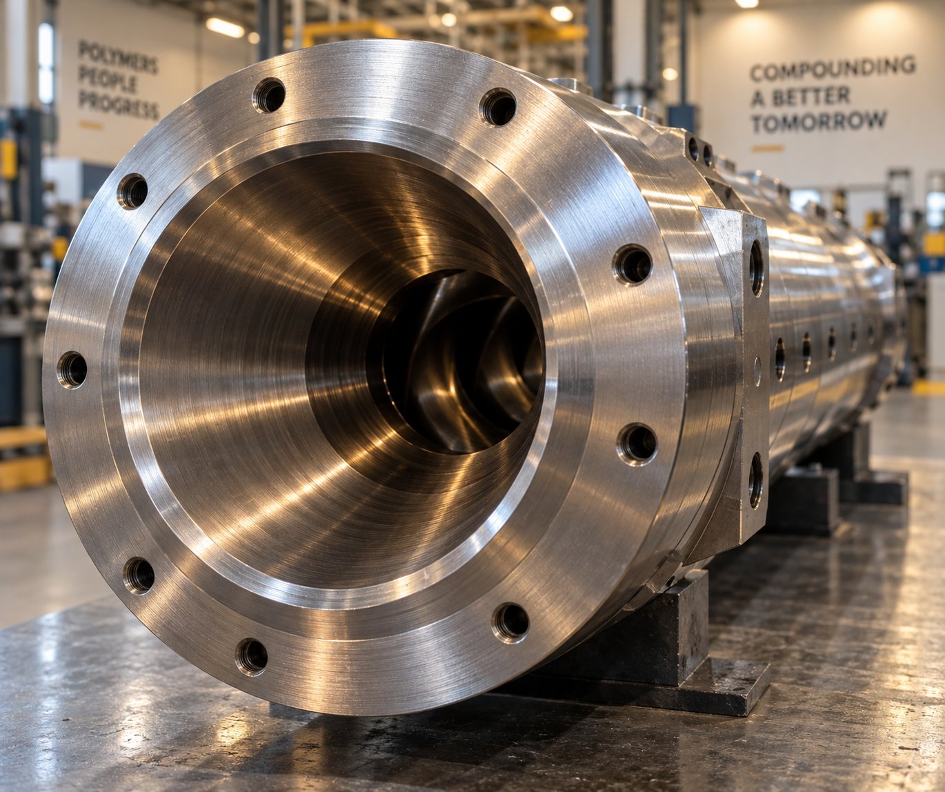
Extruder Barrel For PVC: Why PVC Destroys Barrels Faster
Oct 9, 2026
Learn why PVC destroys extruder barrels faster and how to choose the right barrel material, configuration, and maintenance strategy to maximize service life.
Read ArticleLooking for something else?
Search by material, symptom or product and jump straight to the relevant page.
These are navigation suggestions based on keyword matching — not a quotation, not a delivery commitment, and not a substitute for engineering review. Final specification is confirmed by our engineers against your drawings and processed material.
Need help with screw barrel selection?
Share your machine model, processed material and application. Our team can help with pricing and technical support.