


What Makes Single Screw Extruders Ideal for Sheet Production
A single screw extruder is a plastic extruder that uses one rotating screw inside a heated barrel to convey, melt, and pressurize thermoplastic polymer, pushing a homogeneous melt through a flat die to form continuous sheet. It is the most widely used plasticizing technology in commercial sheet production, trusted by process engineers for its simplicity, reliability, and consistent melt quality across a broad range of resins.
This article is not a generic overview or a product-pitch page. It is a process-engineering-focused guide built exclusively for sheet applications — covering screw geometry, resin-specific processing, downstream integration, troubleshooting, and long-term maintenance. Whether you are specifying a new single screw extruder machine or optimizing an existing line, you will find actionable detail here that moves beyond surface-level explanations.
How a Single Screw Extruder Produces Plastic Sheet
Imagine dropping polymer pellets into a hopper. Gravity feeds them into the barrel's feed zone, where the rotating screw's deep channel flights grab and push them forward. As pellets advance into the compression zone, channel depth gradually decreases, compacting the material against the heated barrel wall. Frictional shear and conducted heat work together to progressively melt the polymer. By the time the material reaches the metering zone — the shallowest section of the screw — it has transformed into a fully molten, pressurized stream. This extrusion extruder mechanism delivers that melt at steady pressure and uniform temperature into a flat die, where it spreads across the full sheet width.
The elegance of this industrial extruder design lies in its three-zone simplicity: convey, melt, meter. Each zone performs a distinct function, yet all three must work in concert to produce sheet with tight gauge tolerances and clean surface finish.
Why Single Screw Remains the Preferred Choice for Sheet Lines
Several practical advantages keep the single screw extruder at the center of sheet production. Capital cost runs significantly lower than twin screw alternatives. Operation is straightforward, spare parts inventory stays manageable, and the technology has decades of proven field reliability behind it. For commodity and engineering resins like PP, PS, PET, PVC, ABS, and PE — the workhorses of sheet extrusion — melt quality from a well-designed single screw is excellent.
Industry consensus holds that over 80 percent of commercial sheet extrusion lines worldwide rely on single screw extruders, a figure reflecting not just cost advantages but the technology's proven ability to deliver consistent melt homogeneity for the vast majority of sheet applications.
Yet "proven" does not mean "simple to optimize." The difference between acceptable sheet and exceptional sheet often comes down to screw geometry — the specific dimensions and features of the screw itself — and how well those details match your resin, your target gauge, and your downstream equipment.
Screw Geometry and Design for Uniform Sheet Quality
Screw geometry is where sheet quality is won or lost. You can dial in barrel temperatures perfectly, run premium resin, and invest in a top-tier flat die — but if the extrusion screw design does not match the material and the application, you will fight gauge variation, surface defects, and inconsistent output every production shift. The screw is not just a conveying device. It is the single component most responsible for melt homogeneity, and melt homogeneity is what determines whether your finished sheet meets spec or gets scrapped.
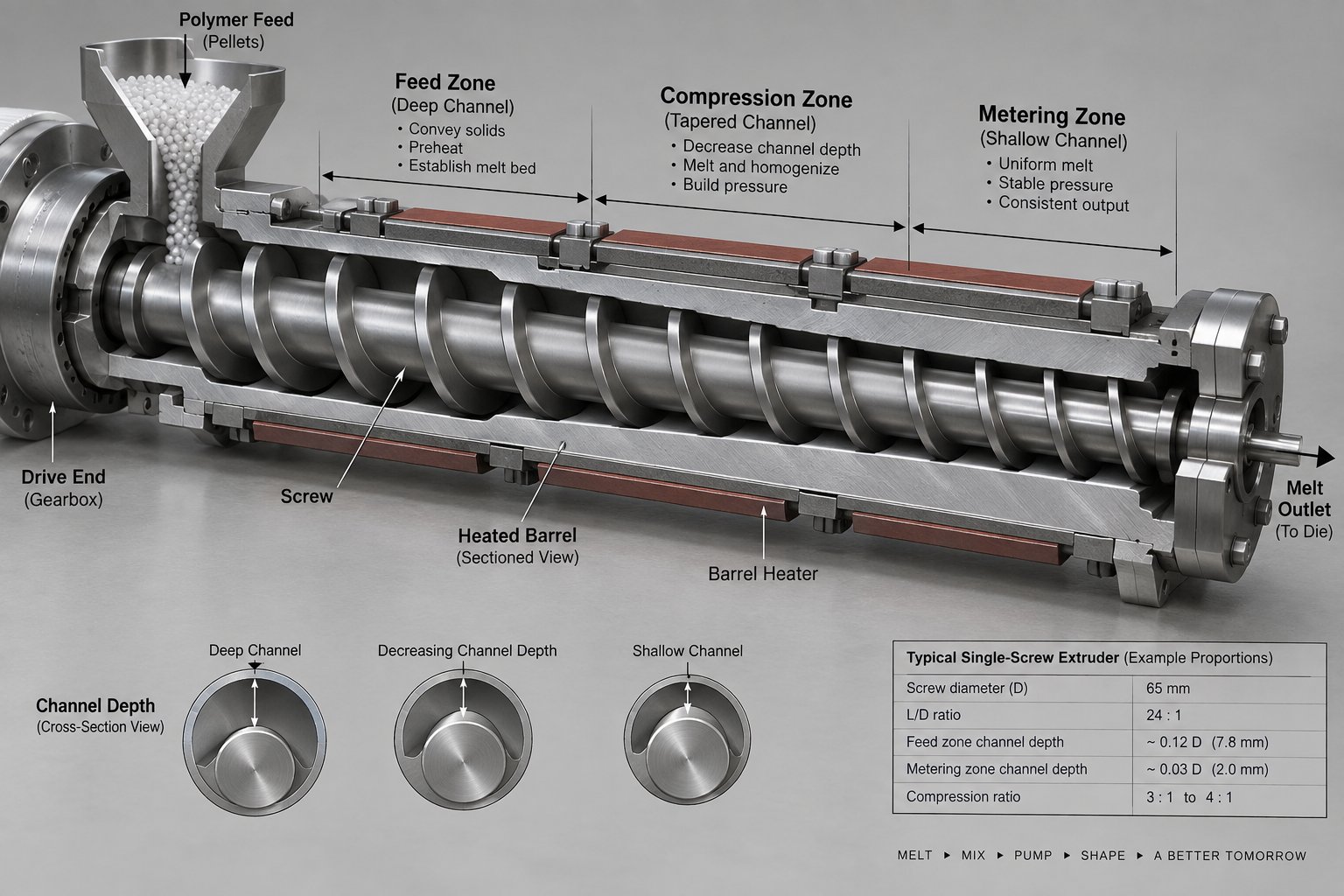
Feed, Compression, and Metering Zones Explained
Every single extruder screw divides into three functional zones, each with a specific channel depth and a distinct job. Understanding what happens in each zone — and how the dimensions interact — gives you the foundation to evaluate any screw design for sheet production.
The feed zone occupies roughly the first third of the screw's working length. Its channel is deep, designed to accept solid pellets from the hopper and convey them forward as a compacted solid bed. Think of it as a volumetric pump for solids. The deeper the channel here, the more material the screw can grab per revolution. If the channel is too shallow, throughput drops. Too deep, and the pellets tumble without building the compaction pressure needed to push material into the next zone.
The compression zone (also called the transition zone) is where the real transformation happens. Channel depth progressively decreases along this section, squeezing the solid bed against the heated barrel wall. That mechanical compression, combined with frictional shear and barrel heat, melts the polymer. The rate at which the channel depth decreases — gradual or aggressive — must match the resin's melting behavior. A polymer that melts quickly can tolerate a shorter compression zone. One that melts slowly or has poor thermal conductivity needs a longer, gentler transition to avoid unmelted particles reaching the die.
The metering zone is the final section, featuring the shallowest and most uniform channel depth. Its purpose is straightforward: deliver a consistent, fully molten stream at stable pressure to the die. For sheet applications, metering zone performance directly controls gauge uniformity. Any pressure pulsation or temperature variation originating here shows up as thickness bands across your sheet.
The relationship between these zones is captured by the extrusion screw compression ratio — feed channel depth divided by metering channel depth. This ratio must match the resin's bulk density and melting characteristics. A mismatch causes real problems: too high a compression ratio generates excessive shear heat and can degrade sensitive polymers, while too low a ratio leaves unmelted particles in the melt stream.
Here is how typical compression ratios break down for common sheet resins:
| Sheet Resin | Typical Compression Ratio | Key Consideration |
|---|---|---|
| PP (Polypropylene) | 2.5 – 3.0 : 1 | Semi-crystalline; moderate shear sensitivity |
| PS (Polystyrene) | 2.5 – 3.0 : 1 | Amorphous; wide processing window |
| PET (Polyethylene Terephthalate) | 2.8 – 3.2 : 1 | Moisture-sensitive; narrow thermal window |
| PVC (Polyvinyl Chloride) | 1.8 – 2.2 : 1 | Heat-sensitive; requires gentle shear |
| ABS (Acrylonitrile Butadiene Styrene) | 2.2 – 2.8 : 1 | Moderate shear needed; impact strength preservation |
| PE (Polyethylene — HDPE/LDPE) | 3.0 – 3.5 : 1 | Low bulk density pellets; needs higher compression |
Notice the range for PVC sits well below the others. That is intentional — PVC degrades rapidly under excessive shear and heat, so the screw must compress it gently. PE sits at the opposite end because its low bulk density pellets require more volume reduction to build adequate melt pressure. Getting this ratio wrong for your specific resin is one of the most common — and most costly — screw specification errors in sheet extrusion.
Barrier Flights and Mixing Elements for Sheet Quality
A conventional three-zone screw works well for many sheet applications, but it has a fundamental limitation: the solid bed and melt pool share the same channel. As melting progresses, the melt film along the barrel wall grows while the solid bed shrinks, but solid fragments can break off and get carried downstream. These unmelted particles — called gels — are especially visible and problematic in clear or thin-gauge sheet where optical clarity matters.
Barrier screw designs solve this problem. A secondary flight — the barrier flight — runs alongside the main flight in the compression zone, creating two separate sub-channels: one for the remaining solid bed and one for the melt pool. The barrier flight clearance is tight enough to prevent solid particles from crossing into the melt channel but allows molten polymer to flow over freely. Maddock-style barrier sections are among the most widely used variants in screw extrusion for sheet, and they measurably reduce gel counts and improve melt temperature uniformity.
Beyond barrier flights, mixing elements added near the end of the metering zone further enhance melt quality. These fall into two categories:
- Dispersive mixing elements — such as Maddock mixers and blister rings — subject the melt to high shear stress that breaks down agglomerates and any remaining unmelt particles. They are essential when processing resins with pigment concentrates or fine additive packages.
- Distributive mixing elements — including pin mixers, pineapple mixers, and Saxton elements — split and recombine the melt stream repeatedly without adding excessive shear heat. They excel at achieving uniform color dispersion and consistent additive distribution across the sheet width.
For sheet extrusion specifically, a combination approach often delivers the best results: a barrier section in the transition zone to eliminate unmelts, followed by a distributive mixer at the metering zone exit to homogenize temperature and composition. This combination tackles both defect types that ruin sheet quality — gels from incomplete melting and streaks from poor mixing.
Selecting the Right L/D Ratio for Your Sheet Application
The length-to-diameter (L/D) ratio determines how much working length the screw has to accomplish conveying, melting, and metering. For sheet extrusion, L/D ratios of 30:1 to 36:1 are standard — and for good reason. Longer screws provide more residence time for complete melting and thorough homogenization, both critical when you need a defect-free melt delivered at high output rates to a wide flat die.
How do you choose within that range? The resin drives the decision. PP and PS sheet can typically run effectively on a screw extruder with a 30:1 L/D ratio. Both resins melt relatively easily, and the shorter length keeps residence time — and thermal exposure — in check. PET sheet, on the other hand, often benefits from 33:1 or even 36:1. PET requires adequate devolatilization to remove residual moisture and acetaldehyde, and the extra screw length provides the processing time needed without pushing screw speed to extremes that generate excessive shear heat.
It is worth noting that a longer L/D ratio is not automatically better. Excessively long screws can cause prolonged residence time, leading to thermal degradation in heat-sensitive materials and increasing energy consumption. The goal is to match the L/D ratio to both the resin's melting and homogenization requirements and the target output rate.
When should you revisit extrusion screw compression ratio adjustments alongside L/D selection? Three scenarios demand it: switching to a resin with significantly different bulk density or melt behavior, increasing output targets beyond the current screw's capacity, or troubleshooting persistent melt quality issues like gels or gauge instability that barrel temperature changes alone cannot resolve. In each case, the compression ratio and L/D ratio should be evaluated together — they are interdependent parameters, not independent knobs.
Getting screw geometry right is the engineering foundation. But even a perfectly designed screw will underperform if it is running the wrong temperature profile or screw speed for the specific resin in the hopper — which is exactly where polymer-specific processing parameters come into play.
Material-by-Material Processing Guide for Sheet Resins
Every resin behaves differently inside a single screw extrusion machine — different melting points, different shear sensitivities, different moisture tolerances, different crystallization behaviors. A barrel temperature profile that produces flawless PP sheet will destroy PVC. A screw speed that works beautifully for PS will generate excessive acetaldehyde in PET. These are not nuances you can afford to learn through trial and error on a production line.
What follows is a polymer-by-polymer processing reference designed as a practical lookup tool. Whether you are dialing in a new polymer extruder setup, troubleshooting an unfamiliar resin, or benchmarking your current parameters against industry norms, this section gives you the starting-point data you need.
PP and PS Sheet Processing Parameters
Polypropylene and polystyrene are the two highest-volume sheet resins processed on single screw extrusion lines, yet they demand very different approaches once you look past the surface similarities.
Polypropylene (PP) is semi-crystalline, meaning its transition from solid to melt is not gradual — it happens over a relatively narrow temperature range. A typical pp extruder barrel profile for sheet runs from 190-200°C at the feed zone, ramping to 220-240°C through the compression and metering zones, with die temperatures in the 220-235°C range. Screw speeds generally fall between 50 and 120 RPM depending on screw diameter and target output, with larger-diameter machines (90 mm and above) running toward the lower end of that RPM range to manage shear heating.
Here is where PP gets tricky for sheet: chill roll temperature. Because PP crystallizes as it cools, the rate of cooling directly controls the sheet's optical clarity, stiffness, and even warpage tendency. Rapid quenching on cold rolls (15-30°C) suppresses large crystal growth and improves transparency — essential for clear thermoforming applications. Slower cooling on warmer rolls (60-80°C) promotes crystallinity and increases stiffness but sacrifices clarity. You will find that many PP sheet quality issues trace back to chill roll settings rather than extruder parameters.
Polystyrene (PS) is amorphous, which gives it a notably wider processing window. Barrel temperatures typically run 180-210°C at the feed section and 210-240°C at the metering zone and die. PS melts smoothly, flows predictably, and does not crystallize — so chill roll temperature control, while still important for surface finish and flatness, is far less critical than with PP.
The practical advantage? PS is forgiving. Screw speed adjustments have a more linear relationship with output, and modest temperature deviations rarely produce catastrophic defects. For process engineers running both resins on the same line, PS is typically the easier changeover. The main caution with PS sheet is excessive residence time at elevated temperatures, which can cause yellowing and brittleness from thermal degradation.
PET and PVC Sheet Processing Considerations
PET and PVC sit at opposite ends of the processing complexity spectrum, but both demand precision that leaves little room for error.
PET (Polyethylene Terephthalate) is arguably the most demanding commodity resin for single screw sheet production. Its sensitivity starts before the extruder — PET is hygroscopic and must be pre-dried to moisture levels below 50 ppm (0.005%) before processing. Skip this step or do it poorly, and hydrolytic degradation will slash the resin's intrinsic viscosity (IV), producing brittle sheet with poor thermoformability. As industry data from PET sheet line manufacturers confirms, well-controlled single screw systems can hold IV loss to 0.02 dL/g or less — but only with proper drying and screw design.
Barrel temperatures for PET sheet typically range from 260-280°C, with die temperatures around 270-280°C. The thermal window is narrow: too cold and you get unmelted particles and haze; too hot and IV drops while acetaldehyde generation spikes — a critical concern for food-contact packaging. Screw design must minimize shear heating, which is why barrier screw geometries with moderate compression ratios (2.8-3.2:1) and L/D ratios of 33:1 or 36:1 are preferred. The longer screw provides adequate residence time for homogenization and devolatilization without forcing high RPM that would generate destructive shear.
PVC (Polyvinyl Chloride) presents a completely different challenge. PVC does not melt in the traditional sense — it fuses. Its processing temperature window sits dangerously close to its thermal degradation temperature. Push too far, and PVC releases hydrochloric acid (HCl) gas, which corrodes equipment and ruins sheet quality. This is why PVC demands low-compression screws (1.8-2.2:1), gentle shear, and precise temperature control across every barrel zone.
Barrel temperatures for PVC sheet typically run 150-175°C, significantly lower than other common sheet resins. Screw speeds are kept moderate to limit shear heating — remember, with PVC, the heat generated by mechanical work is your enemy, not your ally. Many PVC sheet operations use screws with longer feed zones and shallower compression gradients to ensure slow, uniform fusion without localized hot spots. Die temperatures usually fall in the 170-185°C range, and every degree matters.
ABS and PE Sheet Extrusion Guidelines
ABS and polyethylene round out the major sheet resin families, each with processing characteristics that reward attention to detail.
ABS (Acrylonitrile Butadiene Styrene) is a blend of three monomers, and the butadiene rubber phase gives it impact resistance — but that rubber phase is also vulnerable to thermal degradation. Process it too hot or with excessive shear, and you lose impact strength and surface gloss simultaneously. Barrel temperatures for ABS sheet typically range from 210-240°C, with die temperatures around 220-235°C. Compression ratios of 2.2-2.8:1 provide the moderate shear needed for good melting without overworking the rubber component.
ABS also benefits from consistent backpressure. Variations in melt pressure translate directly into surface gloss inconsistencies — glossy and matte bands across the sheet that are immediately visible and impossible to fix downstream. An extruder for polymer blends like ABS should include a mixing element at the metering zone exit to homogenize the melt stream before it enters the die.
Polyethylene (HDPE and LDPE) requires higher compression ratios (3.0-3.5:1) because PE pellets have low bulk density relative to their melt density. Without sufficient compression, the screw cannot build adequate melt pressure for uniform die filling. Barrel temperatures for HDPE sheet run 200-235°C, while LDPE processes at lower temperatures, typically 170-210°C.
The key challenge with PE sheet is melt temperature uniformity. PE's high thermal mass and relatively low thermal conductivity mean temperature gradients develop easily within the melt stream. These gradients cause localized viscosity differences that show up as gauge variation across the sheet width. Backpressure management through proper screen pack selection and, where needed, a melt pump is particularly important for PE sheet to smooth out pressure fluctuations from the screw.
The following table consolidates the essential processing parameters for quick reference:
| Polymer | Barrel Temp Range (°C) | Recommended L/D | Compression Ratio | Key Processing Note |
|---|---|---|---|---|
| PP | 190 – 240 | 30:1 | 2.5 – 3.0 : 1 | Chill roll temp critical for clarity; semi-crystalline cooling behavior |
| PS | 180 – 240 | 30:1 | 2.5 – 3.0 : 1 | Wide processing window; avoid excessive residence time to prevent yellowing |
| PET | 260 – 280 | 33:1 – 36:1 | 2.8 – 3.2 : 1 | Pre-dry to < 50 ppm moisture; minimize shear to preserve IV |
| PVC | 150 – 185 | 24:1 – 30:1 | 1.8 – 2.2 : 1 | Low shear mandatory; degradation releases HCl gas |
| ABS | 210 – 240 | 30:1 – 33:1 | 2.2 – 2.8 : 1 | Moderate shear preserves rubber phase impact strength and surface gloss |
| HDPE | 200 – 235 | 30:1 – 33:1 | 3.0 – 3.5 : 1 | High compression needed for low-bulk-density pellets; manage backpressure |
| LDPE | 170 – 210 | 30:1 | 3.0 – 3.5 : 1 | Melt temperature uniformity critical for gauge control |
Keep in mind that these values represent starting points, not absolute rules. Your specific resin grade, sheet gauge target, screw diameter, and downstream equipment will all influence the final optimized settings. The best approach? Use this table to set your initial parameters, then fine-tune based on measured melt temperature, die pressure stability, and — most importantly — the quality of the sheet coming off the chill rolls.
Of course, even perfectly tuned extruder parameters mean little if the melt leaving the screw encounters a poorly matched die, an undersized chill roll stack, or misaligned downstream equipment. The extruder is one component in a system where every element must work in concert — and that systems-level integration is exactly what separates a good sheet line from a great one.
Complete Sheet Extrusion Line Integration and Downstream Equipment
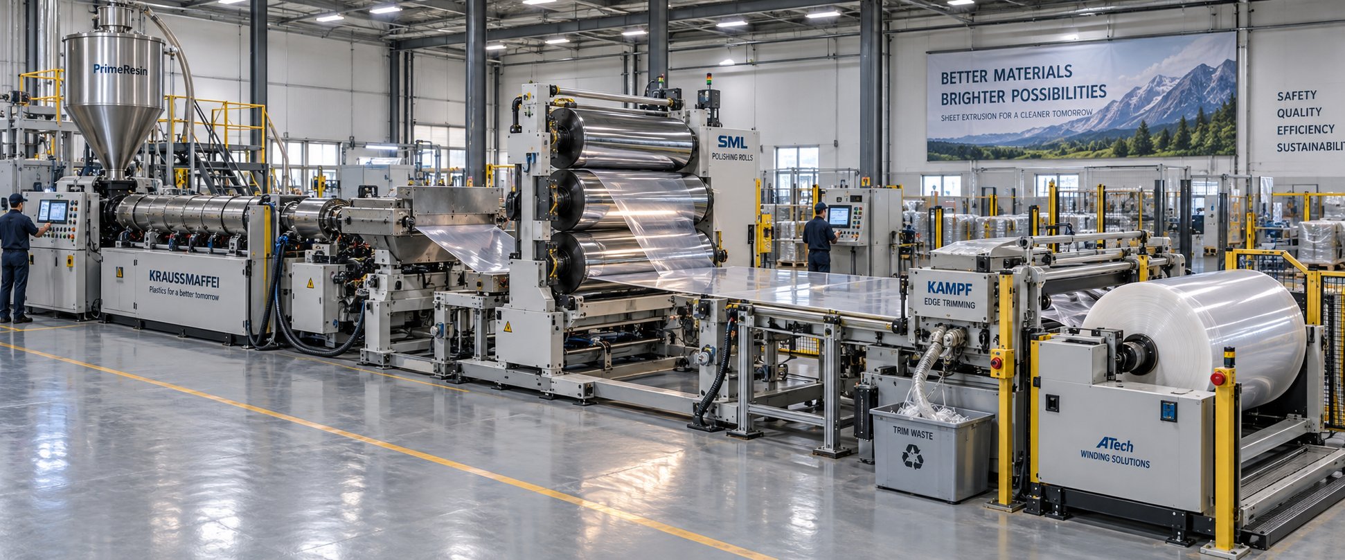
A single screw extruder for sheet does not operate in a vacuum. It is one station in a tightly synchronized production line where every component — from the screen changer behind the screw tip to the winder at the far end of the building — influences the quality of the finished product. You can specify the perfect screw geometry, nail your barrel temperatures, and run premium resin, yet still produce sheet that fails gauge tolerances or shows surface defects because the downstream equipment was mismatched, misconfigured, or simply overlooked during the line design.
Think of it this way: the plastic extruder machine generates the melt. Everything downstream shapes, cools, measures, and packages that melt into saleable sheet. If any single element runs out of sync — a die that cannot distribute flow evenly, chill rolls that cannot remove heat fast enough, or a haul-off that introduces tension variation — the entire line suffers. Understanding the complete process flow is what separates engineers who troubleshoot symptoms from those who solve root causes.
From Extruder Output to Flat Die Distribution
The journey from homogeneous melt inside the metering zone to a wide, uniform sheet profile involves three critical intermediate stages: melt filtration, optional pressure stabilization, and die distribution. Each one addresses a specific risk to sheet quality.
Melt filtration happens first. The melt passes through a screen changer — a device holding one or more wire mesh screens supported by a breaker plate. These screens serve a dual purpose: they filter out solid contaminants, degraded polymer particles, and gels that would otherwise show up as visible defects in the sheet, and they break up the rotational flow memory imparted by the screw. Screen mesh sizes for sheet extrusion typically range from 80 to 200 mesh depending on the resin and the sheet's visual quality requirements. As process guides from Hammer-IMS note, screen condition directly affects back pressure — a blocked screen raises pressure upstream and can shift sheet gauge unless compensated. Continuous or hydraulic slide-plate screen changers allow filter replacement without stopping the line, which is essential for high-volume sheet production.
Next comes the optional melt pump (gear pump). Positioned between the screen changer and the die, this precision device uses two intermeshing gears rotating in a close-fitting housing to deliver volumetrically consistent melt flow regardless of upstream pressure fluctuations. Why does this matter? The single screw extruder inherently produces slight pressure pulsations tied to screw rotation. For thin-gauge sheet or applications demanding tight thickness tolerances, those pulsations translate into gauge bands. A melt pump decouples the die from the extruder's pressure variability, as Plastics Technology's sheet line overview confirms, enabling the die to operate within its designed flow regime with minimal correction.
The melt then enters the flat die — often called a T-die or sheet die — where it must spread from a single circular inlet into a uniform curtain of melt across the full target width. This is where die design becomes critical. Two primary manifold geometries dominate sheet production:
- Coat-hanger dies feature a tapered triangular manifold that gradually reduces in cross-section from center to edges. This geometry equalizes pressure drop across the full width, ensuring melt arrives at the die lips simultaneously regardless of position. According to JWELL's engineering analysis, coat-hanger designs excel with moderate-viscosity polymers like PS, ABS, and PETG, and they are the standard choice for wide sheet applications exceeding 1,000 mm.
- T-slot (fishtail) dies use a straight manifold channel running perpendicular to the exit direction. They are simpler to manufacture and maintain, making them cost-effective for narrower sheet widths. The tradeoff? As die width increases, the pressure differential between the inlet side and the far end becomes harder to manage, narrowing the processing window.
Regardless of manifold type, two adjustment mechanisms fine-tune thickness uniformity across the sheet width. The restrictor bar — an internal, adjustable element upstream of the die lips — handles coarse flow balancing during line setup by locally restricting or opening the melt path. The flex lip — a thin, adjustable steel strip at the die exit — provides real-time gauge correction through push-pull bolts or thermally actuated bolts controlled by an automatic gauge feedback system. Together, these two systems give operators layered control: the restrictor bar sets the baseline distribution, and the flex lip makes the fine adjustments that hold thickness within spec during steady-state production.
Chill Roll Stack, Haul-Off, and Downstream Extruding Equipment
The moment melt exits the die lips, it is still a hot, pliable curtain that must be rapidly cooled, dimensioned, and surface-finished — all simultaneously. This is the job of the three-roll polishing stack, often called the chill roll stack, and it is one of the most underappreciated pieces of plastics extrusion equipment on the line.
A standard configuration uses three vertically arranged, chrome-plated rolls with independent temperature-controlled water circulation. The middle roll is fixed in position while the top and bottom rolls are pressure-loaded against it using pneumatic or hydraulic cylinders. The melt sheet enters the nip between the top and middle rolls, wraps partially around the middle roll, and exits through the nip between the middle and bottom rolls. Roll diameters typically range from 300 mm to 900 mm depending on cooling capacity requirements and sheet gauge.
Three variables at the chill stack control sheet quality:
- Roll temperature determines cooling rate, which affects crystallinity (in semi-crystalline resins like PP), surface gloss, and internal stress. Lower roll temperatures produce faster cooling, higher gloss, and reduced crystallinity — important for clear thermoforming grades.
- Nip pressure between the rolls ensures intimate contact for efficient heat transfer and imparts the final surface texture. Too much pressure causes roll deflection — which, as industry data shows, can create a 3 mil deflection on a 10 mil target gauge, a 30% variance that falls outside any acceptable tolerance.
- Roll surface finish transfers directly to the sheet. Mirror-polished rolls produce glossy sheet; matte-textured rolls produce satin finishes. Matching the roll finish to the end-use requirement is a specification detail often finalized late in line design but difficult to change after installation.
Beyond the chill stack, a series of downstream stations complete the plastic extruding machine line. Haul-off units grip the cooled sheet and maintain constant line tension, which is critical because the ratio of haul-off speed to extruder output rate is the primary lever for controlling final sheet thickness. Even small speed fluctuations here show up as gauge variation. Inline thickness measurement systems — using beta-gauge (nuclear), infrared, or newer millimeter-wave technologies — continuously scan across the sheet width, feeding data back to the die lip actuators for automatic gauge control. Edge trimming stations remove the irregular sheet edges (which are inherently thicker due to die edge effects), with the trim typically reclaimed as regrind for recycling back into the process. Finally, winding systems roll thinner sheet into coils, while cut-to-length stackers shear thicker sheet into individual panels for palletizing.
Here is the complete process flow for a single screw sheet extrusion line, from raw material to finished product:
- Resin feeding and drying (where required for hygroscopic materials)
- Plasticization in the single screw extruder — conveying, melting, and metering
- Melt filtration through a screen changer and breaker plate
- Optional melt pump for pressure stabilization and volumetric consistency
- Flat die distribution — coat-hanger or T-slot manifold spreads melt to full sheet width
- Chill roll polishing and cooling — three-roll stack dimensions, cools, and surface-finishes the sheet
- Inline thickness measurement — continuous scanning with automatic die lip feedback
- Edge trimming — removes uneven edges; trim reclaimed as regrind
- Winding into rolls or sheet cutting and stacking for final product handling
Every station in this sequence depends on the one before it. An extruder machine for plastic sheet that delivers perfect melt quality is wasted on a die that cannot distribute it evenly. A precision die is undermined by a chill stack that cannot remove heat fast enough to match line speed. And all the extruding machines upstream become irrelevant if the haul-off introduces speed pulsations that destroy gauge control.
This interconnectedness is exactly why specifying extruding equipment for a sheet line is a systems engineering exercise, not a component shopping list. Upgrading the extruder without verifying that the die width, chill roll capacity, and haul-off speed range can keep pace is one of the most common — and most expensive — mistakes sheet producers make. The line is only as strong as its weakest link, and that link is often the one nobody checked.
The question, then, is not just whether a single screw extruder is the right plasticizing technology for your sheet application — it almost certainly is for standard resins. The real question is whether a single screw solution covers your specific material and mixing requirements, or whether certain production scenarios genuinely demand a twin screw alternative.
Single Screw vs Twin Screw Extruders for Sheet: A Decision Framework
Most sheet producers do not face a genuinely difficult technology choice. The majority of commercial sheet — PP trays, PS cups, PET packaging, PE liners — runs on single screw platforms because the materials, formulations, and production economics overwhelmingly favor that architecture. The confusion arises because the question is usually framed as "which is better?" when the productive question is "which is right for my specific application?" Those are very different conversations.
A twin screw extruder is not an upgrade from a single screw. It is a different tool designed for a different set of problems. Choosing between them is not about prestige or technical sophistication — it is about matching the machine to the polymer, the formulation complexity, the production pattern, and the budget. Get that match right and you run profitably for years. Get it wrong and you either overspend on capability you never use or underspecify and fight quality problems every shift.
When Single Screw Extruders Excel in Sheet Applications
For the vast majority of sheet production scenarios, a single screw extruder is not just adequate — it is the optimal choice. Here is why, broken down by the factors that actually drive production economics.
Material simplicity favors single screw. When you are processing virgin or lightly filled commodity resins — PP, PS, PE, PET, ABS — the resin supplier has already done the compounding work. The pellets arrive ready to extrude. The single screw's job is straightforward: convey, melt, meter, and deliver a homogeneous stream to the die. A well-designed screw with proper barrier flights and mixing elements handles this task efficiently without the additional mixing intensity that a twin screw provides. As the reference data from JWELL's single vs twin screw comparison confirms, single screw platforms dominate polyolefin and PET sheet production precisely because these materials have forgiving thermal stability, moderate viscosity, and straightforward melting behavior.
Long production campaigns reward simplicity. Sheet lines frequently run the same resin for days or weeks without changeover. In this scenario, the single screw's simpler design becomes a compounding advantage: fewer wear surfaces, lower maintenance intervals, reduced spare parts inventory, and less downtime risk. Every hour the line runs uninterrupted is revenue. A twin-screw extruder's faster changeover capability — its self-wiping screw geometry that clears material quickly — provides no benefit when you are not changing materials.
Throughput efficiency tips the scale. For a given screw diameter, a single screw extruder typically delivers higher output when processing unfilled polymers. The simpler flow path and higher conveying efficiency translate into more kilograms per hour per RPM. A 120 mm single screw processing PP sheet can deliver 800 to 1,200 kg/hr — output levels that would require a significantly larger (and more expensive) twin screw to match.
Economics close the argument. Lower purchase price, lower energy cost per kilogram processed, simpler gearbox design, and a mature technology with well-understood process windows — these are not minor advantages. For sheet producers running commodity resins at volume, the single screw extruder delivers the lowest total cost of ownership by a substantial margin.
When Twin Screw Extruders Become Necessary
Acknowledging single screw strengths honestly means also being transparent about where the technology falls short. There are legitimate production scenarios where twin screw extruders are not just preferred — they are necessary. Ignoring these scenarios leads to quality problems that no amount of process optimization can resolve.
Heavily filled compounds demand intensive mixing. When filler content exceeds 30% by weight — calcium carbonate, talc, mineral additives — a single screw's distributive mixing capability hits its limit. Filler agglomerates survive the melting process because the shear forces in a single screw channel are insufficient to break them down uniformly. The result? A sheet with inconsistent mechanical properties, visible specks, and poor surface finish. Twin screw extrusion solves this through the inter-screw region where material is actively stretched, folded, and recombined — dispersive mixing that a single screw simply cannot replicate. As the AAPS PharmSciTech review on twin screw technology explains, the superior mixing characteristics inherent with a twin screw extruder allowed this device to dominate continuous mixing applications across multiple industries.
Reactive extrusion and in-line compounding require twin screw architecture. If your process involves blending polymers with reactive additives, cross-linking agents, or performing in-line compounding rather than extruding pre-compounded pellets, a twin screw extruder machine provides the controlled residence time distribution and segmented screw design needed to manage these chemical reactions within the barrel. A single screw offers no practical way to achieve the precise sequencing of mixing zones, injection points, and devolatilization stages that reactive processes demand.
Heat-sensitive formulations need narrower residence time control. PVC sheet is the textbook example. PVC degrades rapidly if material stagnates in the barrel — and a single screw inherently has more stagnant zones than a self-wiping twin screw design. Counter-rotating intermeshing twin screw extruders provide positive conveying and a tight residence time distribution that minimizes the risk of thermal degradation and HCl release. This is why, as industry analysis notes, counter-rotating twin screw platforms are strongly preferred for PVC sheet production.
Frequent material changeovers shift the economics. If your production schedule demands switching between different resins or formulations multiple times per week, the self-wiping action of an extruder twin screw design becomes a real cost advantage. Self-wiping screws clear residual material faster, reducing purge waste and changeover time. A single screw, by contrast, requires more extensive purging — and in some cases, physical screw removal — to eliminate contamination between materials. The lost production time and purge material cost can erode the single screw's capital cost advantage surprisingly quickly.
The honest takeaway? A double screw extruder earns its higher price tag only when the application genuinely demands what it offers. For straightforward sheet production with pre-compounded resins, buying a twin screw is paying for capability you will never use.
A Practical Decision Matrix for Sheet Producers
Rhetoric aside, the decision comes down to a handful of concrete criteria. The following matrix maps each criterion to the platform it favors, giving you a structured way to evaluate your specific situation rather than relying on generalized advice or vendor recommendations.
| Decision Criterion | Single Screw Preferred | Twin Screw Preferred |
|---|---|---|
| Material Type | Virgin or pre-compounded commodity resins (PP, PS, PE, PET, ABS) | PVC, wood-plastic composites, reactive blends, multi-component formulations |
| Filler Content | Unfilled or lightly filled (< 30% by weight) | Heavily filled (> 30% mineral fillers, glass fibers) requiring dispersive mixing |
| Production Volume | High-volume, long-run campaigns of a single resin — maximum throughput per dollar invested | Moderate-volume runs where mixing quality or thermal sensitivity outweighs raw throughput |
| Changeover Frequency | Infrequent changeovers (weekly or less) — simpler purging is acceptable | Frequent changeovers (multiple times per week) — self-wiping screws minimize purge waste and downtime |
| Budget | Lower capital investment; 1.5 to 2.5x less than a comparably sized twin screw machine | Higher capital justified by material requirements, quality demands, or reduced scrap/downtime costs |
| Mixing Requirement | Standard melting and homogenization of pre-compounded material; barrier flights and mixing elements sufficient | Intensive distributive and dispersive mixing for compounding, filler dispersion, or reactive processing |
Notice that no single criterion makes the decision in isolation. A sheet producer running virgin PP at high volume with rare changeovers checks every box in the single screw column — the choice is obvious. A producer making highly filled PVC sheet with weekly formulation changes checks every box in the twin screw column — equally obvious. The harder decisions live in the middle ground, where one or two criteria point toward twin screw while the rest favor single screw.
In those borderline cases, consider this: can a screw design modification — adding a more aggressive mixing section, upgrading to a barrier geometry, or extending the L/D ratio — address the mixing shortfall within the single screw platform? Often it can, and the cost of a custom screw is a fraction of the price premium for a twin screw line. Only when the material and formulation fundamentally exceed what single screw architecture can deliver does the twin screw investment become the right engineering decision.
The key to making either platform perform, however, is not just choosing the right one. It is knowing what to do when sheet quality deviates from spec — identifying whether the root cause lives in the extruder, the die, or the downstream equipment, and applying the right corrective action before scrap rates climb.
Troubleshooting Common Sheet Extrusion Defects
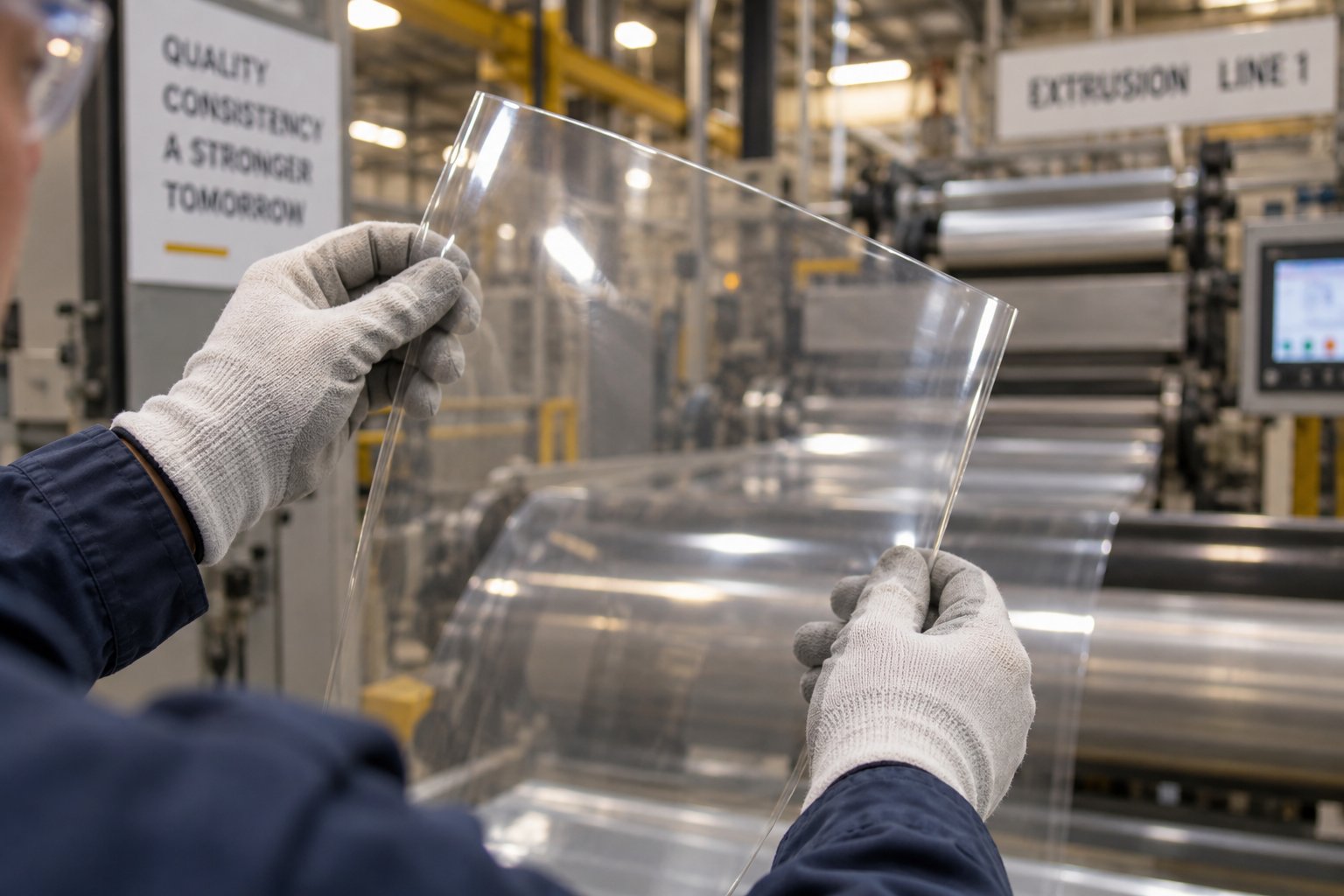
Sheet extrusion defects rarely announce themselves with a single, obvious cause. A surface blemish you spot at the chill roll stack might trace back to a temperature deviation in the second barrel zone, a worn flight edge in the compression section, or a screen pack that should have been changed two hours ago. The challenge is not seeing the defect — it is connecting it to the right upstream variable inside the plastic single screw extruder and applying a corrective action that actually solves the problem rather than masking it.
What follows is a defect-by-defect troubleshooting reference built specifically for single screw sheet lines. Each section identifies the defect, explains the extruder-related mechanisms that cause it, and provides actionable steps you can take on the production floor without shutting down the line — unless the root cause demands it.
Surface Defects and Their Extruder-Related Causes
Surface quality is where sheet extrusion lives or dies commercially. A sheet that meets gauge tolerance but has visible surface flaws gets rejected just as fast as one that is out of spec dimensionally. Three surface defects dominate screw plastic extruder-related quality issues in sheet production.
Die lines are continuous streaks running in the machine direction — thin, linear marks that are especially visible on glossy or transparent sheet. The instinct is to blame the die, and sometimes that is correct: a scratched die lip or a buildup of degraded polymer (plate-out) on the land area will inscribe lines into every meter of sheet that passes through. But die lines can also originate upstream. If the melt arriving at the die contains micro-gels or poorly dispersed additives, those particles lodge at the die lip and create the same streaking pattern. As Wanplas's surface defect analysis explains, die lines require perfect die polishing and precise temperature control — but the corrective action should also include inspecting the screen pack mesh size (stepping up to 150 or 200 mesh can catch particles before they reach the die lip) and checking barrel temperatures for hot spots that accelerate plate-out formation.
Melt fracture produces a distinctive rippled, shark-skin, or spiraling distortion on the sheet surface. It occurs when the melt exits the die at a shear stress exceeding the polymer's critical limit. You will see it more frequently with high-molecular-weight resins, narrow die gaps, and excessive line speeds. Industry troubleshooting guides confirm that reducing extrusion speed or raising die temperature to lower melt viscosity typically resolves melt fracture. From the extruder side, increasing the metering zone temperature by 5-10°C can reduce the shear stress the polymer carries into the die. Processing aids — fluoropolymer-based additives at 500 to 1,000 ppm — are another proven solution for resins prone to this defect.
Poor surface gloss on sheet that should be glossy usually points to one of two root causes: insufficient melt temperature or chill roll surface issues. When the melt exits the die at too low a temperature, its viscosity is high enough that it cannot conform intimately to the polishing roll surface during the brief contact time in the nip. The result is a micro-rough surface that scatters light. Corrective steps include raising the metering zone and die temperatures, verifying that chill roll temperature is appropriate for the resin (too cold can also cause premature freezing before full roll contact), and checking roll surface condition for scratches or contamination.
Thickness Variation and Gauge Control Problems
Gauge uniformity is the specification that defines whether sheet is sellable. A sheet with ±2% thickness tolerance across its width commands premium pricing. One with ±10% variation is scrap — or at best, downgraded to a lower-value application. And while the die lip adjustment and haul-off speed are the most direct levers for gauge control, the root cause of persistent thickness variation almost always traces back to the extruder's melt delivery consistency.
Output surging is the most common extruder-related cause of gauge instability. It manifests as rhythmic, repeating thickness bands in the machine direction — thick-thin-thick-thin at intervals that often correlate with screw rotation frequency. Surging happens when the solid bed in the feed zone breaks apart prematurely or bridges across the screw channel, creating intermittent rather than continuous solids conveying. Each interruption produces a momentary pressure drop at the die, and that pressure drop translates directly into a thin band on the sheet.
What causes feed zone instability? Several factors, often working together:
- Pellets bridging in the feed throat due to excessive feed zone barrel temperature — the outer surface of pellets softens and sticks together before entering the screw channel
- Inconsistent pellet size or regrind mixed with virgin resin, creating uneven bulk density at the feed opening
- Worn feed zone flights that have lost their ability to grip and convey solids efficiently
Screw and barrel wear is a subtler but equally destructive source of gauge problems. As the clearance between the screw flight OD and the barrel bore increases with wear, melt leaks backward over the flights instead of being pushed forward. This backflow reduces net pumping efficiency and creates pressure fluctuations that the die cannot compensate for — especially in screw extruders running without a melt pump. Process engineering references note that worn screws reduce mixing efficiency and create inconsistent melt temperatures, both of which compound gauge variation in the finished sheet.
Actionable corrective steps for thickness variation include:
- Reduce feed zone barrel temperature to prevent pellet bridging (often 10-20°C below the resin's softening point)
- Verify that the feed throat cooling water is circulating and at the correct temperature
- Measure screw flight OD and barrel bore ID — if clearance exceeds 0.10-0.15 mm per side on the metering section, wear is likely contributing to surging
- Install or verify function of a melt pump between the extruder and die to decouple pressure pulsations from die flow
- Check die lip gap settings and restrictor bar positions for proper cross-web flow balance
Gels, Moisture Defects, and Degradation Issues
Gels, moisture-related splay marks, and thermal degradation share a common trait: they are all contaminants in what should be a perfectly homogeneous melt stream. Each has a distinct appearance and a distinct root cause inside the plastic extruders and material handling system.
Gels appear as small, raised bumps or translucent specks in the sheet — particularly noticeable in clear PS, PET, and PP grades. They are unmelted or cross-linked polymer particles that survived the plasticating process and made it through the screen pack. Surface defect studies attribute gels to cross-linked polymer or foreign material that has not melted properly, often compounded by stagnant zones in the barrel or die where material sits too long and degrades. From a screw design perspective, gels point to inadequate mixing in the metering zone or an L/D ratio too short for the resin to achieve complete melting. Adding a barrier flight section to separate solids from melt — as discussed in the screw geometry section — is the most effective long-term fix. In the short term, increasing barrel temperature in the compression zone by 5-10°C and stepping up the screen pack mesh from 100 to 150 or 200 mesh can reduce gel pass-through.
Moisture defects show up as splay marks — silver streaks or small bubbles on or just beneath the sheet surface. They are caused by water vapor flashing to steam inside the barrel and getting trapped in the melt. Hygroscopic resins like PET and nylon are the primary offenders: PET requires pre-drying to below 50 ppm moisture, and nylon to below 0.1% by weight. Even non-hygroscopic resins can exhibit moisture defects if pellets are stored improperly or if the feed hopper is open in a humid environment. The fix is straightforward but non-negotiable — dry the resin properly before it enters the extruder. A dehumidifying dryer with a dew point of -40°C or lower is essential for PET sheet production. No extruder setting can compensate for wet resin.
Thermal degradation manifests as yellowing, brown specks, or a burnt odor. It results from excessive melt temperature — either from barrel temperature settings that are too high, from excessive shear heat generated at high screw speeds, or from material stagnating in dead zones within worn barrel sections or poorly designed die manifolds. PVC is the most susceptible resin: degradation releases hydrochloric acid gas that corrodes equipment and creates a cascade of quality and safety problems. The corrective approach involves reducing barrel temperatures in the affected zone, lowering screw RPM to decrease shear heating, and inspecting the barrel for worn areas where material can hang up. As JWELL's engineering troubleshooting reference notes, residence time depends on the extruder's L/D ratio and line speed — longer residence time increases the risk of thermal degradation for heat-sensitive materials.
The following checklist consolidates the defect-cause-action relationships into a quick-reference format for production floor use:
- Die lines → Root cause: damaged die lip, plate-out buildup, or micro-gels lodging at die exit. Action: polish die lips, increase screen pack mesh size, check barrel hot spots causing degradation.
- Melt fracture / shark skin → Root cause: excessive shear stress at die exit from high line speed or low melt temperature. Action: reduce screw RPM, raise metering zone and die temperature by 5-10°C, consider fluoropolymer processing aid.
- Poor surface gloss → Root cause: melt temperature too low for intimate chill roll contact, or roll surface contamination. Action: raise metering/die temperatures, verify chill roll temperature and surface condition.
- Gauge surging (rhythmic thickness bands) → Root cause: solids bridging in feed zone or screw/barrel wear reducing pumping consistency. Action: reduce feed zone temperature, verify feed throat cooling, measure screw/barrel wear, add melt pump.
- Cross-web thickness variation → Root cause: improper die lip gap or restrictor bar settings, uneven die temperature. Action: adjust flex lip bolts using gauge scan data, verify all die heater zones functioning, balance restrictor bar.
- Gels / unmelts → Root cause: inadequate screw mixing, insufficient L/D ratio, or low compression zone temperature. Action: increase compression zone temperature, upgrade screen pack mesh, consider screw retrofit with barrier flights and mixing section.
- Splay marks / moisture bubbles → Root cause: insufficient resin drying for hygroscopic polymers (PET, nylon, PC). Action: verify dryer dew point (-40°C or lower), confirm drying time and temperature per resin spec, check hopper seals.
- Yellowing / brown specks / burnt odor → Root cause: thermal degradation from excessive barrel temperature, high shear heat, or material stagnation in worn barrel areas. Action: reduce barrel temperatures, lower screw speed, inspect barrel for wear-related dead zones, purge system thoroughly.
One pattern runs through every item on this list: defects that appear at the sheet surface almost always originate inside the extruder or in material preparation upstream of it. Chill rolls, die lips, and haul-offs can amplify problems, but they rarely create them from scratch. That is why effective troubleshooting starts at the hopper and works forward — checking resin condition, barrel temperatures, screw condition, and screen pack status before adjusting anything downstream.
Troubleshooting fixes today's production problems. But some quality challenges are structural rather than situational — built into the feedstock itself. As regulatory pressure drives sheet producers toward higher percentages of recycled content, the variability inherent in post-consumer and regrind materials introduces a new layer of complexity that demands both screw design adaptations and process strategy rethinking.
Processing Recycled Materials and Optimizing Energy Efficiency
Regulatory mandates across the EU, North America, and parts of Asia now require minimum recycled content in packaging sheet — 25% to 30% post-consumer resin (PCR) in many jurisdictions, with targets climbing toward 50% within the next few years. For sheet producers running single screw extrusion lines built and optimized for virgin pellets, this shift is not optional. It is a material change in the feedstock itself, and it introduces variability that touches every aspect of the process: feed behavior, melt consistency, filtration load, and finished sheet quality.
The good news? A single screw extruder can handle recycled content effectively — but not without intentional modifications to screw design, downstream filtration, and process control strategy. Running regrind or PCR the same way you run virgin resin is a recipe for elevated scrap rates, shortened screen changer intervals, and customer complaints about gels and haze. The plastic extrusion cost implications of getting this wrong add up fast.
Challenges of Running Regrind and Post-Consumer Resin
Why is recycled material harder to process than virgin pellets? The answer is variability — in nearly every property that matters for stable extrusion.
Inconsistent bulk density is the first problem you encounter at the feed throat. Virgin pellets arrive in uniform size and shape, flowing freely into the screw channel with predictable packing density. Regrind, by contrast, comes in irregular flakes, chips, and fragments that pack unpredictably. Post-consumer resin may arrive as pellets, but their size distribution is often wider than virgin grades. This inconsistency means the feed zone does not grab the same volume of material with every screw revolution, leading to output fluctuations that propagate through the entire line as gauge instability in the finished sheet.
Contaminants raise the filtration burden dramatically. Even well-sorted PCR streams contain trace levels of foreign polymers, paper fiber, adhesive residue, aluminum fragments, and degraded polymer particles. These contaminants clog screen packs faster, demanding more frequent screen changes. On a virgin-only line, you might change screens every 8 to 12 hours. With 30% PCR content, that interval can shrink to 2 to 4 hours — a significant hit to uptime if your screen changer requires a line stop.
Variable melt viscosity compounds the challenge. Mixed resin lots — even those nominally the same polymer — often contain material from multiple suppliers, different production runs, and varying degradation histories. Each batch melts and flows slightly differently, creating viscosity gradients in the melt stream that the die cannot fully compensate for. The visible result? Gauge bands and flow lines in the sheet that were never present when running 100% virgin material.
Moisture variability is especially problematic in post-consumer PET and nylon streams. PCR may have been stored outdoors, transported through humid environments, or inadequately dried at the reclamation facility. If moisture levels fluctuate from lot to lot — or even within a single gaylord — the extruder sees intermittent splay marks and IV degradation that come and go unpredictably.
The cumulative effect on sheet quality is measurable: more gels and specks, wider gauge variation, reduced optical clarity, and potential odor issues from volatile contaminants that were not present in virgin feedstock. For producers evaluating used plastic extruders or used extrusion lines for recycled content applications, these challenges should factor directly into the equipment specification — a machine that performed flawlessly on virgin resin may need significant upgrades to handle PCR at commercial quality levels.
Screw and Process Modifications for Recycled Sheet Production
Adapting a single screw sheet line for recycled content starts inside the barrel — with the screw design and barrel configuration.
Grooved feed sections address the bulk density problem directly. A grooved feed zone — where longitudinal or helical grooves are machined into the barrel wall in the solids conveying area — dramatically improves the grip on irregular, low-bulk-density regrind. Instead of relying solely on friction between the barrel wall and the compacted material, the grooves mechanically lock the solid bed against the barrel, forcing it forward regardless of particle shape or packing density. As Far East Network's screw design reference explains, the feed section's channel depth and geometry must be balanced with downstream compression — and grooved feed barrels effectively decouple feed performance from particle uniformity, making output more consistent even with variable regrind.
Enhanced mixing sections become essential when melt viscosity varies from batch to batch. A standard full-flight screw may produce acceptable melt homogeneity with consistent virgin pellets, but it lacks the mixing intensity to homogenize variable-viscosity recycled streams. Adding a Maddock mixer or pin-mixing section in the metering zone forces the melt through multiple splitting and recombination events, smoothing out viscosity gradients before the melt reaches the die. For sheet applications where optical clarity matters — clear PET or PP trays, for instance — this mixing upgrade is the difference between sellable and scrap sheet.
Vented barrel configurations tackle moisture and volatile contamination without relying entirely on upstream drying. A vented (or two-stage) screw design incorporates a decompression zone partway along the screw length, where the channel depth suddenly increases. This creates a low-pressure zone where moisture and volatile organic compounds flash off and escape through a barrel vent port — often connected to a vacuum pump for enhanced devolatilization. For PCR streams with unpredictable moisture content, vented barrels provide a critical safety net. Wanplas's recycling-focused extruder models, for example, incorporate degassing vents specifically to handle moisture and volatiles from regrind, which is essential for maintaining intrinsic viscosity in materials like PET.
Continuous melt filtration systems deserve particular emphasis for recycled sheet production. Manual slide-plate screen changers that worked fine on virgin lines become a bottleneck when contamination loads increase by 3x to 5x. Continuous screen changers — either belt-type or rotary designs — advance fresh screen area into the melt path without stopping the line, maintaining consistent backpressure even as contamination accumulates. Pairing a continuous screen changer with a melt pump downstream creates a powerful stabilization system: the screen changer handles contamination, and the melt pump smooths out the pressure fluctuations that screen changes inevitably introduce. For producers investing in used extruder equipment for recycled content operations, verifying that the filtration system is sized and configured for the higher contamination loads of PCR is at least as important as evaluating the extruder itself.
Energy Efficiency and Cost Optimization Strategies
Running recycled content adds process complexity, but the broader operational economics of a single screw sheet line — energy consumption, drive efficiency, and thermal management — determine whether the line runs profitably regardless of feedstock type. Energy is typically the second-largest operating cost after raw material, making efficiency gains directly impactful on margins.
Specific energy consumption — measured in kWh per kilogram of sheet produced — is the benchmark that matters. Well-optimized single screw sheet lines typically operate in the range of 0.14 to 0.22 kWh/kg, depending on resin type, screw diameter, and drive system efficiency. PET sheet, with its higher processing temperatures and drying requirements, falls toward the upper end. PP and PS lines, running at lower barrel temperatures with simpler material handling, achieve the lower figures. Tracking this metric over time reveals whether the line is drifting toward inefficiency — and often flags screw and barrel wear before quality problems become visible.
Servo-driven motors and premium AC drives deliver measurable energy savings compared to older hydraulic or constant-speed AC motor setups. A servo motor adjusts torque and speed dynamically to match actual processing demand rather than running at full power continuously. Industry data from high-efficiency extruder analyses indicates that upgrading from a standard AC drive to a premium IE3/IE4 motor with vector-controlled variable frequency drive can reduce motor energy consumption by 15% to 25% — savings that, on a line running 8,000 hours per year, translate to tens of thousands of kilowatt-hours annually. When evaluating used extrusion lines for purchase, the drive system vintage and efficiency class should factor into the total cost of ownership calculation, not just the sticker price.
Heating zone optimization offers additional savings that are often overlooked. Ceramic insulation blankets wrapped around barrel heater bands reduce radiant heat loss to the surrounding environment by up to 40%, meaning the heaters cycle on less frequently to maintain setpoint temperatures. The investment is modest — a few hundred dollars per zone — and energy audits on production extruders show payback periods under 12 months for most installations. Equally important is barrel cooling zone management: inverter-controlled cooling fans that modulate speed based on actual zone temperature — rather than running at full speed whenever the zone exceeds setpoint — eliminate the energy waste and temperature overshoot problems that plague on/off cooling systems.
Proper screw and barrel maintenance is one of the most overlooked energy efficiency strategies: as wear increases the screw-to-barrel clearance, pumping efficiency drops, the screw must turn faster to maintain the same output, shear heating increases, and specific energy consumption rises — a compounding cycle where a worn screw can increase energy use by 10% to 15% before quality defects become obvious enough to trigger replacement.
This wear-driven efficiency loss connects energy management directly to maintenance planning. A screw and barrel that are replaced proactively — based on measured dimensional wear rather than waiting for visible quality problems — pay for themselves partly through avoided energy waste, not just through improved sheet quality. That maintenance dimension is exactly where the next section picks up: understanding wear patterns, metallurgical solutions, and replacement economics that keep a single screw sheet line performing at its engineered potential over years of continuous production.
Screw and Barrel Maintenance for Consistent Sheet Quality
A single screw plastic extruder running sheet operates under conditions that accelerate wear in ways that general-purpose extrusion does not. Sheet lines run continuously — often 24 hours a day, 5 to 7 days a week — at high output rates that keep screw speeds elevated and barrel pressures sustained for thousands of hours between shutdowns. That relentless duty cycle means wear is not a question of if but where, how fast, and what it costs you in sheet quality before you catch it. Understanding these wear patterns — and matching the metallurgical solutions to your specific resin and production profile — is the difference between predictable maintenance costs and emergency shutdowns that blow through both budgets and delivery schedules.
Screw and Barrel Wear Patterns in Sheet Extrusion
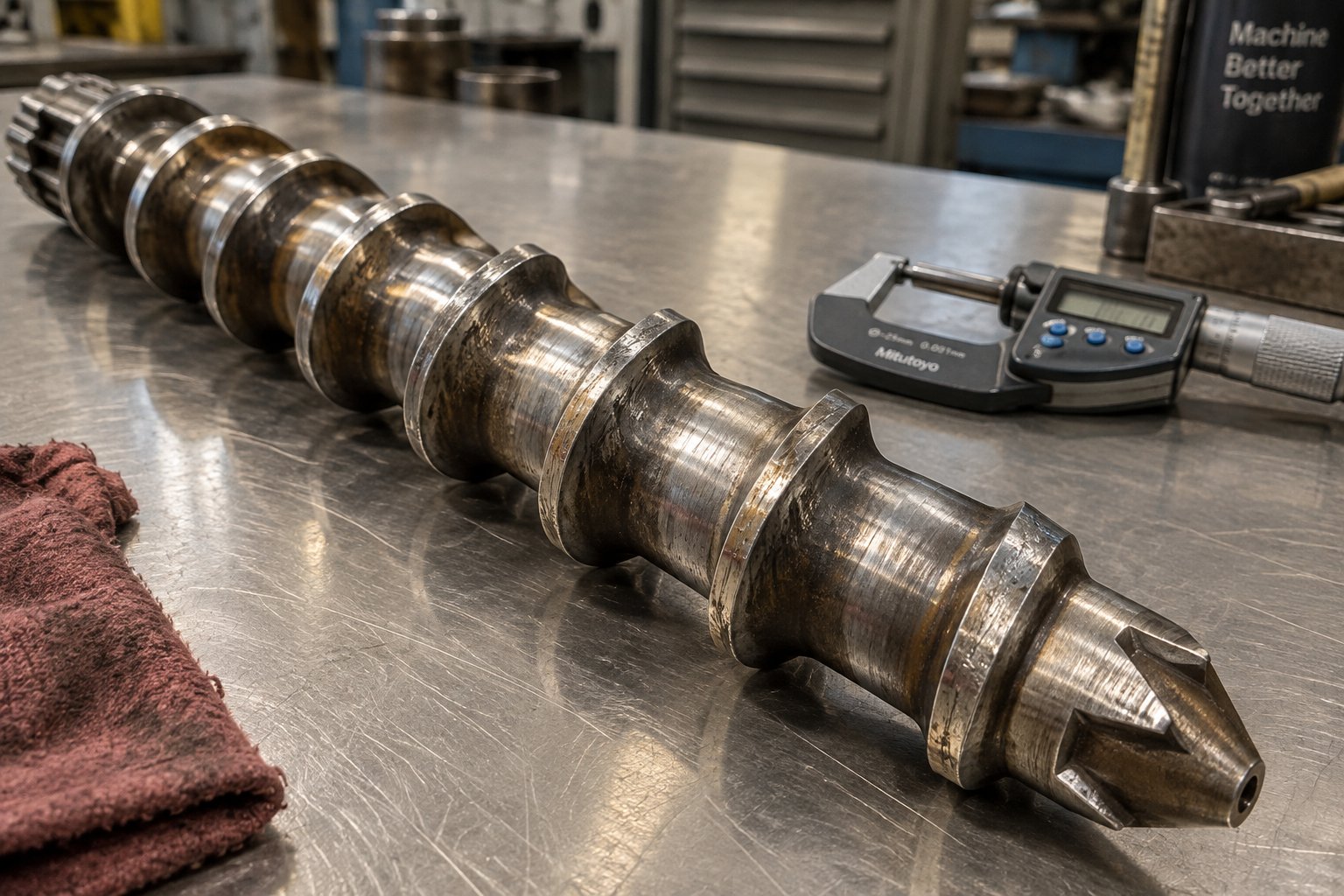
Wear inside a single screw plastic extruder machine does not happen uniformly along the barrel length. It concentrates in predictable zones, each driven by a different mechanism — and each producing a distinct impact on sheet quality when clearances grow beyond engineered tolerances.
The compression zone takes the hardest hit in most sheet applications. This is where the solid polymer bed is being compacted against the barrel wall under the highest combination of pressure and shear. The transition from solid to melt creates abrasive contact as partially melted pellets are forced against both the screw flights and the barrel bore. Over thousands of operating hours, flight tips lose material and the barrel bore enlarges — widening the clearance that allows melt to leak backward over the flights instead of being pushed forward.
The metering zone wears most aggressively when the resin contains abrasive fillers — talc, calcium carbonate, glass fiber, or titanium dioxide. Even at modest filler loadings of 10% to 20%, the fully molten stream carrying hard particles acts like liquid sandpaper against the flight OD and barrel ID. For sheet producers running filled PP or ABS compounds for thermoforming applications, metering zone wear often progresses faster than compression zone wear, making it the first section to exceed clearance limits.
The feed zone is vulnerable primarily when processing glass-filled engineering resins or running heavily contaminated regrind. Solid glass fibers are highly abrasive against both the screw root and barrel wall before the polymer matrix melts and encapsulates them. Even for unfilled sheet resins, feed zone wear occurs at the barrel bore near the feed opening, where incoming pellets create localized abrasion as the screw flights sweep them into the channel.
What happens to sheet quality as these clearances grow? The consequences follow a predictable and escalating pattern. As JWELL's screw and barrel replacement guide details, increased clearance allows more melt to leak backward over the flights, reducing net pumping efficiency. Operators compensate by increasing screw speed, which raises shear heating and melt temperature — often without realizing the root cause. The result is a compounding cycle: output surging produces gauge bands in the sheet, elevated melt temperature degrades heat-sensitive resins, and specific energy consumption climbs as the screw works harder to deliver the same throughput. By the time these symptoms become obvious on the sheet, the wear has typically progressed well beyond the point where a simple screw speed adjustment can compensate.
This is why measurement-based maintenance — not symptom-based reaction — is the standard among high-performing sheet operations. Waiting for visible quality defects to trigger an inspection means the wear has already cost you months of sub-optimal production.
Bimetallic Barrels and Coated Screws for Extended Service Life
The metallurgy of your screw and barrel is the first line of defense against the wear mechanisms described above. A standard nitrided steel barrel running an abrasive or corrosive resin will wear significantly faster than one engineered with wear-resistant materials matched to the application. Choosing the right combination is a materials science decision that pays dividends over the full service life of the components — often doubling or tripling the interval between replacements compared to general-purpose metallurgy.
Bimetallic barrel liners are the industry standard for demanding sheet applications. These barrels feature a centrifugally cast inner liner of wear-resistant alloy metallurgically bonded to a structural steel outer shell. Two alloy families dominate:
- Nickel-boron alloys — excellent for general-purpose abrasion and moderate corrosion resistance. They handle unfilled commodity resins and lightly filled compounds well, making them the default choice for PP, PS, and PE sheet lines running primarily virgin material.
- Tungsten carbide-based alloys — engineered for severe abrasive wear from heavily filled compounds, glass-reinforced resins, or high-contamination recycled streams. Their hardness (typically 55-65 HRC) far exceeds standard nitrided barrels and resists the gouging action of hard filler particles. Sheet operations running mineral-filled PP or glass-filled ABS benefit substantially from this upgrade.
For corrosion-dominated wear — PVC sheet being the primary example — specialized nickel-chromium-molybdenum alloy liners provide the chemical resistance needed to withstand HCl attack. Running a standard bimetallic barrel on a PVC sheet line is a costly mistake: the corrosion will undercut the wear-resistant surface from beneath, causing premature liner failure.
Screw flight hard-facing protects the component most exposed to abrasive contact. Two hard-facing alloys are widely used by single screw extruder manufacturers and rebuild specialists:
- Stellite alloys (cobalt-chromium) — provide excellent abrasion resistance and maintain hardness at elevated temperatures. They are the preferred choice for screws processing mineral-filled sheet resins where flight tip wear is the primary failure mode.
- Colmonoy alloys (nickel-based) — offer a good balance of abrasion and corrosion resistance at a lower cost than Stellite. They are widely used for general-purpose sheet applications and moderate filler loadings.
For single screw sheet lines processing unfilled commodity resins — where wear is moderate and cost sensitivity is high — full-depth nitrided screws provide adequate hardness (typically 55-70 HRC surface layer) at the lowest component cost. Nitriding creates a hard iron-nitride layer on the screw surface without altering its dimensions, making it a practical solution for general-purpose sheet extrusion where aggressive abrasion is not the primary concern.
The critical principle? Match the metallurgy to the resin and filler system you are actually running — not to a generic recommendation. A screw hard-faced with Stellite running unfilled PP is over-specified and wastes money. A nitrided screw running 30% glass-filled nylon will be worn out in months. The mismatch in either direction costs you — either in unnecessary component expense or in premature replacement and lost production time. Reputable extruders manufacturers and barrel suppliers will ask detailed questions about your resin, filler content, processing temperatures, and production hours before recommending a metallurgical specification — and that consultative approach is exactly what you should expect.
When to Replace vs. Rebuild Your Screw and Barrel
Every screw and barrel eventually reaches a point where continued operation costs more in lost efficiency, elevated scrap rates, and energy waste than replacement. The challenge is identifying that point objectively — through measurement, not guesswork.
The measurement process is straightforward in concept: compare the current screw outside diameter (OD) and barrel inside diameter (ID) at corresponding axial locations against the original engineering drawings or documented new-condition baseline. As detailed wear assessment protocols recommend, measure at defined positions along the barrel length — feed section, compression section, vent section (if applicable), and metering section — and at multiple angular orientations to detect ovality. Calculate the diametral clearance (barrel ID minus screw OD) at each location and compare against the OEM's specified allowable limits.
A critical nuance: there is no universal replacement clearance. Allowable clearance depends on screw diameter, polymer viscosity, operating pressure, and product tolerance requirements. A clearance that is acceptable on a large-diameter, low-pressure PE sheet extruder may be completely unacceptable on a smaller-diameter PET sheet line running tight gauge specifications. Always reference the machine manufacturer's specific limits — and when those are unavailable, consult with experienced plastic extruder suppliers who can evaluate wear data against performance requirements for your application.
Three options exist once wear is confirmed:
- Continue and monitor — when dimensions remain within approved limits and sheet quality targets are still being met. Shorten the inspection interval if the wear rate is accelerating between measurements.
- Rebuild the screw — when flight wear is repairable (hard-facing can be re-applied to worn flight tips) and the screw core, straightness, and base metallurgy remain sound. A qualified rebuild specialist should document restored geometry, coating hardness, and dimensional conformance. Screw rebuilds typically cost 40% to 60% of new component pricing and can restore near-original performance.
- Replace the barrel, the screw, or both — when cracks, deep scoring, severe ovality, extensive corrosion, or accumulated previous rebuilds make restoration unreliable. The screw and barrel must always be evaluated as a matched pair: installing a new screw into a badly worn barrel leaves excessive clearance that will shorten the new screw's life and fail to resolve the pumping efficiency problems that triggered the replacement decision.
When replacement is the right call, sourcing matters. A replacement barrel that does not match the original bore dimensions, liner alloy, or heat treatment specification will underperform from day one. This is where working with an application-specific manufacturer makes a measurable difference. NANHAIYA, for example, manufactures custom and replacement single screw barrels engineered specifically for sheet extrusion applications — including bimetallic options designed for the resin families and wear profiles that sheet lines encounter. Their manufacturing scope covers sheet, film, pipe, pelletizing, and recycling applications, which means the metallurgical and dimensional expertise is backed by real production experience across the plastics extrusion equipment landscape, not just catalog specifications. When you need a replacement barrel that matches original tolerances and is specified for the exact resin and operating conditions your line demands, that kind of application-focused capability ensures the new component integrates seamlessly and delivers the service life your production economics require.
Regardless of whether you rebuild or replace, the following warning signs should trigger immediate measurement and evaluation — do not wait for the next scheduled shutdown:
- Decreased output at the same screw RPM — the clearest indicator of lost pumping efficiency from increased flight-to-barrel clearance
- Increased melt temperature at the same barrel settings and RPM — excess clearance forces more melt recirculation, generating additional shear heat that raises melt temperature without any process change
- Visible surging in sheet gauge readings — rhythmic thickness bands in the machine direction that correlate with screw rotation and cannot be resolved through temperature or speed adjustments
- Increased specific energy consumption (kWh/kg) — the screw is working harder to deliver the same output, a direct consequence of reduced volumetric efficiency
- Higher motor amperage at unchanged operating conditions — worn screws demand more torque to maintain output, stressing the drive system and increasing electricity costs
- Declining sheet surface quality — gels, streaks, or gloss inconsistencies that progressively worsen over weeks or months, suggesting degrading melt homogeneity from reduced mixing effectiveness
Tracking these indicators over time — ideally plotted against operating hours and logged alongside resin type, filler content, and screw/barrel measurement data — transforms maintenance from reactive firefighting into predictable cost management. The best sheet operations treat screw and barrel wear the same way they treat die lip condition or chill roll surface finish: as a measurable, manageable variable that is monitored proactively and addressed before it reaches the finished product.
Maintenance keeps the line running at its engineered potential. But even a perfectly maintained extruder is only one component in a system — and specifying the right single screw extruder for a sheet application requires looking beyond the barrel and screw to define every parameter that determines whether the complete line delivers the output, quality, and efficiency your production targets demand.
How to Specify a Single Screw Extruder for Your Sheet Application
Every parameter discussed throughout this guide — screw geometry, resin-specific processing, downstream integration, maintenance metallurgy — converges at a single practical moment: writing the specification. Whether you are evaluating a plastic extruder for sale, requesting quotes for a new line, or benchmarking an existing machine against current production demands, a structured specification eliminates guesswork and protects you from costly mismatches between equipment capability and application requirements.
Key Specification Parameters for Sheet Extruder Selection
A specification that omits even one critical parameter invites a supplier to fill the gap with their default — which may not match your resin, your gauge target, or your throughput requirement. The following table captures the parameters every buyer or engineer must define before engaging with extruder machine for sale listings or manufacturer quotations.
| Specification Parameter | Typical Range for Sheet | Selection Depends On |
|---|---|---|
| Screw Diameter | 60 mm – 150 mm | Target output rate (kg/hr), resin type, and sheet width; larger diameters deliver higher throughput |
| L/D Ratio | 30:1 – 36:1 | Resin melting behavior and devolatilization needs; PET typically requires 33:1–36:1, PP and PS run well at 30:1 |
| Compression Ratio | 1.8:1 – 3.5:1 | Resin bulk density and thermal sensitivity; PVC needs 1.8–2.2:1, PE needs 3.0–3.5:1 |
| Drive Power | 75 kW – 500 kW | Screw diameter, target RPM, resin viscosity, and required torque for filled vs. unfilled materials |
| Maximum Screw RPM | 80 – 200 RPM | Resin shear sensitivity; heat-sensitive resins (PVC, PET) require lower maximum RPM to limit shear heating |
| Barrel Heating Zones | 5 – 10 zones | L/D ratio and resin complexity; more zones provide finer temperature profiling for demanding resins |
| Barrel Metallurgy | Nitrided steel to bimetallic (Ni-B or tungsten carbide) | Resin corrosiveness (PVC demands corrosion-resistant alloys), filler abrasiveness, and target service life |
| Cooling Capacity | Water-cooled feed throat + zone-specific barrel cooling | Feed zone cooling prevents pellet bridging; downstream cooling zones manage shear-induced overheating |
Notice that no parameter exists in isolation. Choosing a 120 mm screw diameter but pairing it with an undersized 90 kW motor limits the RPM range and chokes throughput potential. Specifying a 36:1 L/D ratio for a PP sheet line adds unnecessary residence time and energy cost. Every row in this table interacts with every other row — and the resin you are processing determines the right answer for all of them.
When specifying or replacing screw barrels as part of this process, working with a manufacturer that engineers components for specific sheet extrusion applications ensures dimensional and metallurgical compatibility with the overall line specification. NANHAIYA, for instance, produces custom-engineered single screw barrels covering sheet, recycling, and general-purpose extrusion — a range that means the barrel specification can be matched precisely to the resin, filler system, and service life requirement your application demands, rather than forcing a generic off-the-shelf component into a purpose-built line.
Building a Complete Sheet Line Specification
Here is where many specification exercises fail: the extruder gets detailed attention while everything downstream receives a one-line description. That imbalance creates lines where a perfectly specified extruder feeds into a die that cannot distribute its output evenly, or pushes melt faster than the chill roll stack can cool it. Building a complete specification means coordinating every major component.
Die width and type must match your target sheet width and resin. A coat-hanger die is the standard for wide sheet above 1,000 mm. If you are producing narrower specialty sheet, a T-slot die may suffice at lower cost — but confirm the manifold geometry can handle your resin's viscosity profile without creating flow distribution problems at the edges.
Chill roll diameter and temperature control precision must match the resin and gauge you are producing. Semi-crystalline resins like PP demand tight roll temperature control (often ±1°C) to manage crystallinity and clarity. Larger roll diameters provide more contact area and cooling capacity for thicker gauges and faster line speeds. If you are evaluating extrusion equipment for sale or comparing pvc extrusion machine price quotations, verify that the roll temperature control system meets these precision requirements — a bargain chill stack with ±5°C temperature swing will produce sheet that no amount of extruder optimization can fix.
Line speed must be matched to extruder output capacity. A 120 mm single screw extruder producing 600 kg/hr of PP requires a haul-off, thickness gauge, edge trimmer, and winder all rated for the corresponding line speed at your target sheet width and gauge. Upgrading the extruder from 90 mm to 120 mm without verifying that every downstream station can keep pace is one of the most common and expensive mistakes in sheet line specification.
Downstream equipment sizing follows the same principle: the screen changer must handle the filtration area and contamination load for your material (especially critical for recycled content), the melt pump must match the extruder's volumetric output range, and the winder or stacker must accommodate the roll diameters or sheet dimensions your customers require.
Specifying a single screw extruder for sheet is not about the extruder in isolation — it is about designing a balanced, integrated extrusion system where every component is sized, rated, and coordinated to deliver the target output, quality, and efficiency as a unified production line.
When reviewing extruders for sale or assembling a specification package for a new line, resist the temptation to optimize the extruder independently and treat the rest as afterthoughts. A plastic extruder machine for sale listing may highlight impressive screw diameter and drive power numbers — but those numbers mean nothing if the die, chill stack, and downstream equipment are not specified to the same level of rigor. Start with the finished sheet requirements — width, gauge, resin, output rate, quality tolerances — and work backward through the line to derive each component's specification. That systems-first approach is what separates a specification that produces sheet profitably from one that produces headaches.
Engineers building their specification package can reference NANHAIYA's single screw barrel catalog as a practical resource for barrel dimensions, metallurgical options, and application-specific configurations — a useful starting point for ensuring the barrel component of your specification aligns with the rest of the line.
Frequently Asked Questions About Single Screw Extruders for Sheet Production
1. What is the best L/D ratio for a single screw extruder used in sheet extrusion?
For most sheet extrusion applications, L/D ratios between 30:1 and 36:1 are standard. PP and PS sheet typically run well at 30:1, while PET sheet benefits from 33:1 or 36:1 due to its need for adequate devolatilization and longer homogenization time. Choosing an excessively long L/D ratio for resins that do not require it adds unnecessary residence time, increases energy consumption, and can cause thermal degradation in heat-sensitive polymers. The optimal ratio depends on your specific resin, target output rate, and sheet quality requirements.
2. How do I choose the right compression ratio for my sheet resin?
Compression ratio — the feed channel depth divided by the metering channel depth — must match the resin's bulk density and melting characteristics. PVC requires the lowest ratios (1.8-2.2:1) because it degrades under excessive shear. PE needs the highest (3.0-3.5:1) due to its low pellet bulk density. PP and PS fall in the 2.5-3.0:1 range, PET at 2.8-3.2:1, and ABS at 2.2-2.8:1. A mismatched ratio causes either excessive shear heating and degradation (too high) or unmelted particles and gels in the finished sheet (too low). Suppliers like NANHAIYA can engineer replacement barrels matched to these screw specifications for precise compatibility.
3. When should I use a single screw extruder instead of a twin screw for sheet production?
A single screw extruder is the optimal choice when processing virgin or lightly filled commodity resins such as PP, PS, PE, PET, and ABS in long production campaigns. It delivers lower capital cost, simpler operation, reduced maintenance, and higher throughput per dollar compared to twin screw alternatives. Twin screw extruders become necessary only when filler content exceeds 30%, reactive extrusion or in-line compounding is required, highly heat-sensitive formulations demand tight residence time control, or frequent material changeovers make self-wiping screws economically advantageous.
4. What causes gauge variation in single screw sheet extrusion and how do I fix it?
The most common extruder-related cause of gauge variation is output surging — rhythmic pressure fluctuations from solids bridging in the feed zone or from screw and barrel wear increasing flight-to-barrel clearance. Corrective steps include reducing feed zone barrel temperature to prevent pellet sticking, verifying feed throat cooling, measuring screw OD and barrel ID for wear beyond 0.10-0.15 mm per side clearance, and installing a melt pump between the extruder and die to decouple pressure pulsations. Cross-web thickness variation typically points to improper die lip gap settings or uneven die temperature zones.
5. How do I know when to replace the screw and barrel on my sheet extrusion line?
Key warning signs include decreased output at the same screw RPM, increased melt temperature without process changes, visible surging in gauge readings, rising specific energy consumption (kWh/kg), and declining sheet surface quality. Measure screw OD and barrel ID at defined positions along the barrel length and compare against original specifications. When clearance exceeds manufacturer limits, evaluate whether a screw rebuild (typically 40-60% of new cost) is viable or full replacement is needed. Always assess the screw and barrel as a matched pair, and source replacements from application-specific manufacturers like NANHAIYA to ensure dimensional and metallurgical compatibility.
Written by
Nanhaiya Technical Team
Zhoushan Nanhaiya Plastic Machinery Co., Ltd.
The Nanhaiya technical team supports screw and barrel manufacturing projects through application review, technical communication, custom manufacturing coordination, and production and quality control.
Discuss Your Application
Related Articles
More insights on screw barrel technology and plastics processing.

What Nobody Tells You About Screw Barrel For Plastic Machine Design
Oct 10, 2026
Learn how screw barrel for plastic machine design affects melt quality, throughput, and wear life. Covers geometry, resin matching, troubleshooting, and sourcing.
Read Article
PE Pipe Extruder Machine: What Datasheets Won't Tell You
Oct 9, 2026
Learn how a PE pipe extruder machine works, key specs explained, material grade selection, maintenance tips, and buyer guidance beyond the datasheet.
Read Article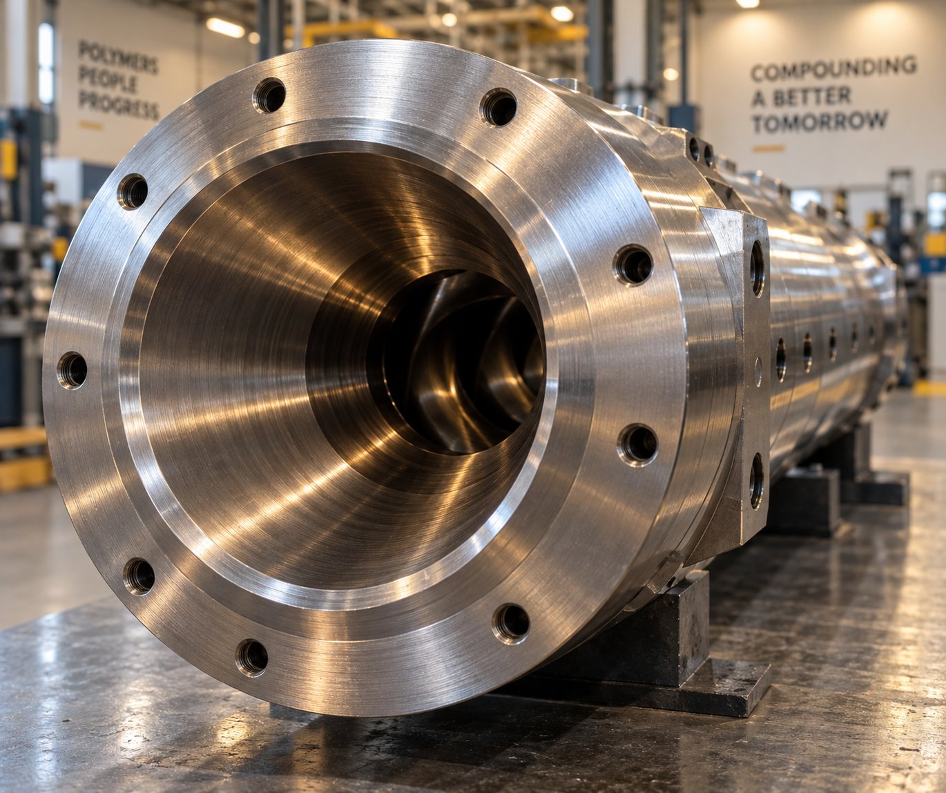
Extruder Barrel For PVC: Why PVC Destroys Barrels Faster
Oct 9, 2026
Learn why PVC destroys extruder barrels faster and how to choose the right barrel material, configuration, and maintenance strategy to maximize service life.
Read ArticleLooking for something else?
Search by material, symptom or product and jump straight to the relevant page.
These are navigation suggestions based on keyword matching — not a quotation, not a delivery commitment, and not a substitute for engineering review. Final specification is confirmed by our engineers against your drawings and processed material.
Need help with screw barrel selection?
Share your machine model, processed material and application. Our team can help with pricing and technical support.