

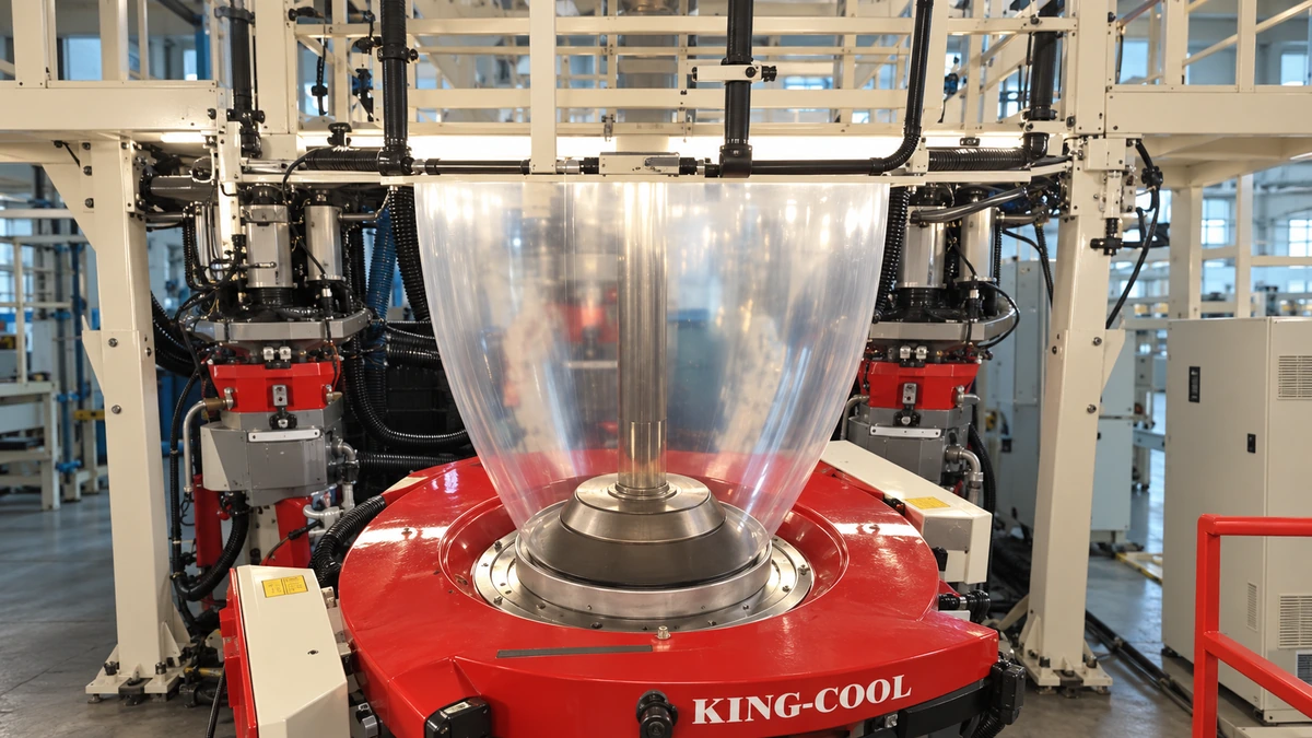
Understanding Blown Film Problems From Resin to Roll
What Are Blown Film Problems and Why They Matter
Blown film problems are the full spectrum of visual defects, process instabilities, and mechanical failures that can occur at any stage of blown film extrusion — from the moment resin enters the hopper to the second a finished roll leaves the winder. These issues include everything from gels and melt fracture at the die exit to bubble instability mid-tower, gauge variation across the web, and wrinkles or blocking in downstream rolls.
Why should you care? Because in packaging blown film production, even a small, recurring defect can cascade into hours of scrap, rejected shipments, and costly downtime. A single unstable bubble doesn't just waste material — it stalls an entire line. As Swallow Machinery highlights, high-speed extrusion lines operate with multiple interacting variables where small fluctuations quickly escalate into production inefficiencies.
Most troubleshooting guides focus on isolated defects — a list of symptoms and quick fixes. This guide takes a different approach. It's a resin-to-roll resource covering every stage of the blown film line, designed to serve three distinct audiences. Operators need to visually identify defects and make real-time corrections on the floor. Process engineers need to understand why specific parameter interactions create specific failure modes. Plant managers need a broader view of how preventive maintenance schedules, resin selection, and environmental factors drive long-term quality and throughput.
The major categories of blown film manufacturing issues you'll encounter across the line include:
- Melt and die issues — gels, degradation, die lip buildup, and melt fracture
- Bubble formation instabilities — helical instability, draw resonance, and bubble breathing
- Gauge variation — uneven thickness across the web or along the machine direction
- Surface defects — fish eyes, specks, haze, and contamination marks
- Downstream roll-quality failures — wrinkles, blocking, telescoping, and poor corona treatment
The Five Root Variables Behind Every Defect
Here's what years of blown film troubleshooting consistently reveal: no matter how complex a defect appears, its root cause almost always traces back to one of five core variables. Understand these, and you have a diagnostic framework that applies to virtually any problem on the line.
Most blown film problems trace back to one of five root variables — temperature, pressure, resin rheology, mechanical wear, or environmental conditions. Identifying which variable is driving a defect is the single most important step in effective troubleshooting.
- Temperature — barrel zones, die lip heating, melt temperature, and cooling air temperature all influence melt behavior and film properties
- Pressure — back pressure, internal bubble pressure, and air ring velocity directly affect output consistency and bubble shape
- Resin rheology — melt index, melt strength, and molecular weight distribution determine how a polymer responds to stretching, cooling, and orientation
- Mechanical wear — screw and barrel degradation, die surface condition, and roller alignment deteriorate gradually, making them easy to overlook
- Environmental conditions — ambient temperature, humidity, and plant airflow patterns shift seasonally and can silently destabilize an otherwise optimized process
These variables rarely act alone. A change in ambient temperature might shift your frost line height, which alters gauge distribution, which then shows up as telescoping on finished rolls. Recognizing these chain reactions is what separates reactive firefighting from systematic blown film troubleshooting.
Each defect you'll see on your film or your bubble is telling you something specific about which of these variables has drifted — and the sections ahead decode exactly what your bubble is saying.
Visual Identification of Common Blown Film Defects
Knowing the five root variables gives you a diagnostic framework — but frameworks only work when you can accurately name what you're looking at. And here's the problem: many blown film extrusion defects look frustratingly similar to the untrained eye. A gel and a fish eye can appear nearly identical on a fast-moving web, yet they point to completely different root causes and demand completely different corrective actions. Misidentify one, and you'll chase the wrong fix for an entire shift.
Let's break down exactly what each major film defect looks like, feels like, and where it shows up.
Gels vs Fish Eyes vs Un-Melts — How to Tell Them Apart
These three defects account for the majority of visual complaints in blown film, and they're constantly confused with one another. The key is paying attention to size, transparency, texture, and distribution pattern.
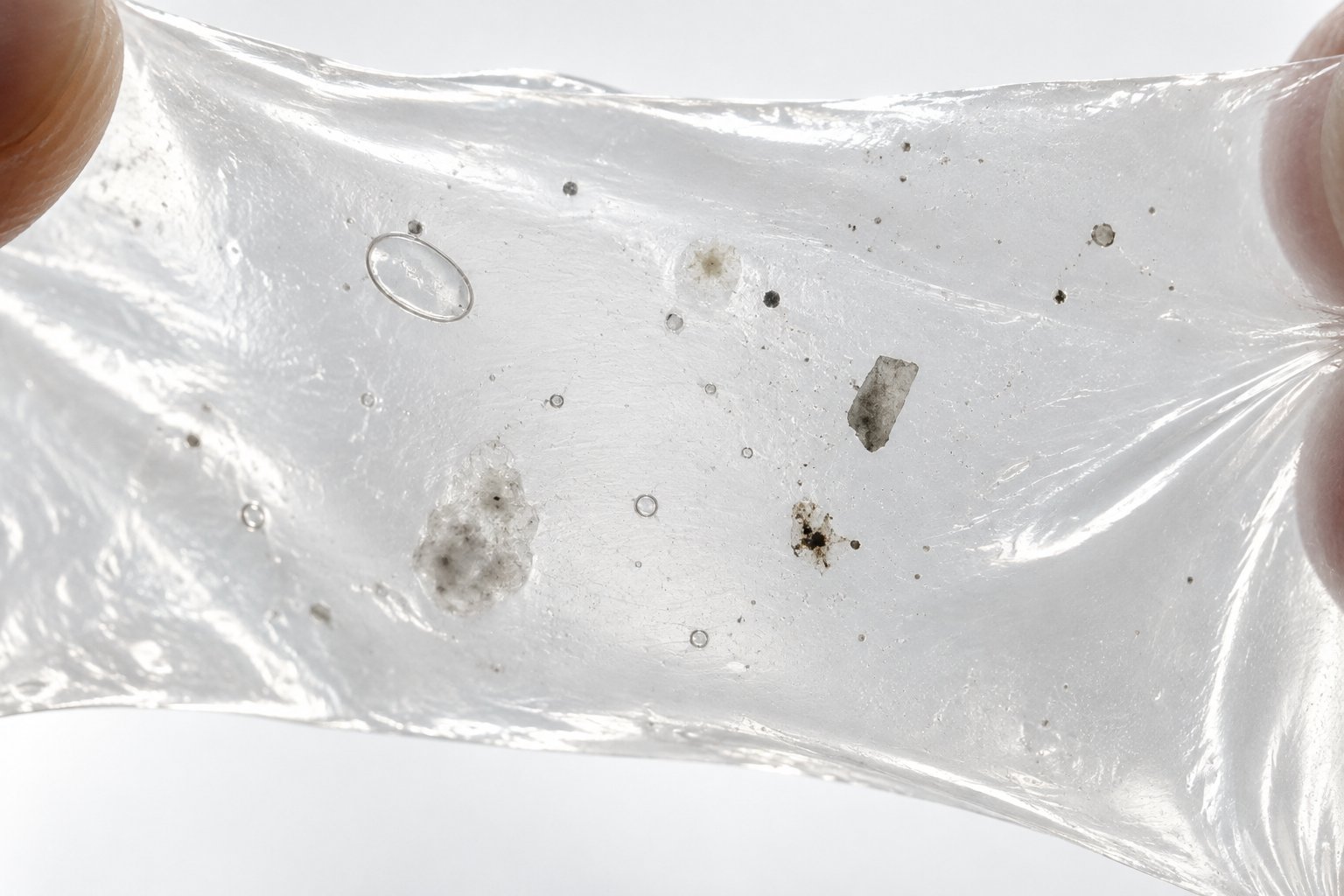
Gels are small, smooth, translucent or semi-transparent raised spots embedded within the film structure. They typically range from 0.1 mm to 2 mm in diameter and feel like tiny bumps when you run your finger across the surface. Gels are caused by degraded resin, crosslinked material, or buildup inside processing equipment that breaks loose into the melt stream. Their distribution is usually random and sporadic — you'll see them scattered without a repeating pattern.
Fish eyes look similar at first glance, but there's a critical visual difference. Each fish eye has a distinct circular "halo" or ring surrounding a central nucleus, giving it an appearance that resembles — you guessed it — the eye of a fish. They're typically larger than gels, often 1 mm to 5 mm across, and the center point may appear opaque or slightly discolored. Fish eyes usually originate from un-dispersed additives, moisture, or high-molecular-weight polymer fractions that didn't fully integrate into the melt.
Un-melts are the easiest to distinguish if you know what to look for. They appear as opaque, irregularly shaped particles that are clearly not part of the surrounding matrix. Unlike gels, which are smooth and embedded, un-melts have rough or grainy textures and may protrude from the film surface. They indicate insufficient melting — either from low barrel temperatures, excessive throughput, or worn screw flights that reduce mixing efficiency.
Melt Fracture and Surface Roughness Identification
Melt fracture presents an entirely different visual signature. Instead of isolated spots, you'll notice a widespread surface distortion affecting entire sections of film. The texture can range from a subtle matte roughness — sometimes called sharkskin — to severe, wavy distortions that look like bamboo ridges or spiral patterns running along the extrusion direction.
What causes it? When the polymer melt exits the die, shear rates exceeding the critical threshold create unstable flow, and the melt surface literally fractures. LDPE-type resins tend to show random surface roughness first, while HDPE-type linear polymers progress from smooth to regular spiral or bamboo-shaped distortions before reaching random fracture at very high shear rates. Imagine running your fingertip across affected film — instead of the glassy smoothness you'd expect, you'll feel a consistent, sandpaper-like texture or visible rippling.
Corrective approaches include reducing screw speed, increasing melt temperature to lower viscosity, or modifying the die geometry. Adding processing aids can also push the critical shear rate higher, giving you a wider operating window.
Specks and Contamination — Reading the Evidence
Black specks and colored contamination are their own category of thin film troubleshooting challenges. Black specks are almost always carbonized material — resin that degraded from excessive heat exposure inside the barrel, adapter, or die and eventually broke free into the melt stream. They appear as dark, hard, irregularly shaped particles embedded in the film. If you see them increase during startup, the likely culprit is material that degraded during the previous shutdown.
Crosslinked specks, by contrast, are often lighter in color — amber or yellowish — and feel harder than surrounding film when pressed between your fingers. These form when polymer chains chemically bond together under sustained high temperatures, creating insoluble particles that no amount of reprocessing will eliminate.
The table below summarizes each defect's identifying features to help operators quickly narrow down what they're seeing:
| Defect Name | Visual Appearance | Location on Film | Common Confusion | Primary Cause Category |
|---|---|---|---|---|
| Gels | Smooth, translucent raised bumps (0.1–2 mm); random distribution | Embedded within the film structure | Fish eyes, un-melts | Resin degradation, equipment buildup |
| Fish Eyes | Circular halo around an opaque center nucleus (1–5 mm) | Embedded, often visible from both sides | Gels | Un-dispersed additives, moisture, high-MW fractions |
| Un-Melts | Opaque, irregularly shaped, rough or grainy texture | May protrude from the film surface | Gels, crosslinked specks | Insufficient melting temperature or mixing |
| Melt Fracture | Widespread surface roughness, sharkskin texture, or spiral/bamboo distortions | Entire film surface or repeating bands | Die lines (but die lines are narrow, linear streaks) | Excessive shear rate at die exit |
| Black Specks | Dark, hard, irregularly shaped particles | Embedded within the film | Crosslinked specks, external contamination | Carbonized degraded resin |
| Crosslinked Specks | Amber or yellowish hard particles | Embedded, sometimes with surrounding distortion | Gels, black specks | Chemical crosslinking from sustained heat |
Collect and label physical film samples of each defect type with the date, resin lot, and processing conditions. These reference samples become your most valuable training tool — they allow operators to compare live defects against known examples instead of relying on verbal descriptions alone.
Accurate identification is not just an academic exercise. Calling a gel a fish eye sends you adjusting additive dispersion when you should be inspecting for barrel buildup. Confusing melt fracture with die lines leads to unnecessary die disassembly when reducing screw speed might solve the problem in minutes. Every corrective action starts with seeing the defect clearly — and the next critical question is whether those defects are constant or fluctuating, which points directly to bubble stability and gauge variation.
Bubble Instability and Gauge Variation Explained
A scattered gel or an occasional fish eye is frustrating — but it's manageable. You trim the affected footage, adjust a parameter, and keep running. Bubble instability and gauge variation are a different beast entirely. These aren't occasional blemishes; they produce continuous scrap. When the bubble dances, breathes, or spirals, every meter of film coming off the line is suspect until the process is stabilized. That's why these rank among the most costly blown film problems any operation can face.
So what's actually happening inside that bubble when it goes unstable? The answer lives at the intersection of processing parameters and polymer science — and understanding both is the key to regaining control.
Bubble Instability Modes and Their Root Causes
Not all instability looks the same. Watch a troubled bubble closely, and you'll notice it misbehaves in distinct, recognizable patterns. Each pattern — or instability mode — points to a different underlying cause.
Helical instability shows up as a spiraling or corkscrew motion in the bubble between the die and the frost line. Imagine the bubble slowly rotating around its axis while it inflates. This spiral creates a repeating thickness pattern that wraps around the layflat like a barber pole stripe. The root cause is almost always asymmetric cooling — one side of the air ring delivering more airflow than the other, or an environmental draft hitting the bubble from a single direction. A radial temperature differential as small as 1°C can trigger gauge variation increases of approximately 7% in polyolefin films.
Draw resonance is a periodic, rhythmic pulsation where the bubble diameter and film thickness oscillate in a regular cycle. You'll see the bubble "breathe" in and out at a consistent frequency — but unlike random bubble breathing, draw resonance follows a predictable wave pattern. It occurs when the take-up ratio pushes the melt beyond its extensional stability limit. The polymer can't sustain uniform stretching at that rate, so it oscillates between over-stretched and under-stretched states. Linear polymers like LLDPE are particularly vulnerable here because they lack the strain-hardening behavior needed to self-correct during stretching.
Bubble breathing looks like slow, irregular expansions and contractions of the bubble diameter. Unlike draw resonance's predictable rhythm, breathing tends to be erratic and harder to anticipate. It typically traces back to fluctuations in internal bubble pressure — either from inconsistent air supply, small leaks in the IBC (internal bubble cooling) system, or unstable melt delivery from the extruder creating pressure surges at the die.
| Instability Type | Visual Symptom on Bubble | Key Processing Parameters to Check | Corrective Action |
|---|---|---|---|
| Helical Instability | Spiraling or corkscrew motion; repeating spiral gauge pattern on layflat | Air ring uniformity, ambient drafts, die centering | Profile air ring radial velocity to achieve less than ±3% uniformity; eliminate environmental drafts; re-center the die |
| Draw Resonance | Regular, periodic pulsation of bubble diameter and thickness | Take-up ratio (TUR), melt temperature, resin melt strength | Reduce TUR; lower melt temperature to increase melt strength; blend in LDPE to improve strain-hardening; adjust blown film coolers for faster solidification |
| Bubble Breathing | Irregular, erratic expansion and contraction of the bubble | Internal bubble pressure, IBC system integrity, extruder output consistency | Check IBC for leaks; stabilize air supply pressure; verify consistent screw speed and back pressure; inspect for surging |
How BUR and TUR Interact to Create Gauge Variation
Plenty of troubleshooting guides tell you to "adjust BUR" or "reduce TUR" when gauge variation appears. But why do these parameters matter, and how do they interact?
The blow-up ratio (BUR) controls how much the bubble expands radially — essentially, how far the melt stretches in the transverse direction after leaving the die. A higher BUR means more transverse stretching. The take-up ratio (TUR), sometimes called the draw-down ratio, controls how fast the nip rolls pull the film upward relative to the die exit speed — governing the stretch in the machine direction.
Here's what matters: BUR and TUR are not independent dials. They're competing demands on the same molten polymer tube. When you increase BUR, you're asking the melt to stretch more sideways. When you increase TUR, you're pulling it faster upward. The melt has a finite capacity to accommodate both stretches simultaneously, and that capacity is governed by the polymer's extensional viscosity — its resistance to being stretched in any direction.
Push the BUR beyond safe limits — typically around 4:1 for standard polyethylene — and you'll see thinning at the edges of the layflat and sagging sections where the melt couldn't sustain the stretch. Crank the TUR too high while keeping BUR low, and neck-in distortion develops along with thickness swings of ±7% or more. The sweet spot requires balancing both ratios so the melt stretches uniformly in all directions without exceeding its extensional limits.
When gauge variation appears, check BUR and TUR together — never in isolation. Adjusting one without accounting for the other simply shifts the instability from one direction to another.
The die gap also plays a critical role in this balance. A wider die gap provides more melt volume, which gives the polymer a longer time to stretch before solidifying. This can compensate for higher BUR values. A narrower die gap reduces melt volume and makes the bubble more sensitive to both BUR and TUR settings — less room for error.
Frost Line Height and Cooling Rate Effects
The frost line — that visible boundary where the molten tube transitions from clear to opaque — is one of the most important visual indicators on any blown film line. Its height above the die tells you how quickly the polymer is solidifying, and that solidification rate directly controls bubble stability and final film properties.
When blown film coolers push the frost line lower (faster cooling), the melt solidifies sooner, which generally improves bubble stability by locking the polymer into shape before instabilities can develop. But there's a tradeoff: cooling too aggressively can freeze the polymer before it has fully oriented, reducing clarity and mechanical properties. It can also create excessive stress at the frost line, leading to haze or brittleness.
A higher frost line (slower cooling) gives the melt more time to stretch and orient, which can improve clarity and toughness. The risk? A taller molten zone means more unsupported melt is exposed to environmental disturbances. Wind from an open bay door, airflow from a nearby HVAC vent, or even heat radiating from adjacent equipment can push that extended melt zone off-center, triggering helical instability or asymmetric gauge patterns.
This is where polymer science becomes practical. The polymer's melt strength — its ability to resist deformation under its own weight — determines how tall a melt zone it can sustain before sagging or drifting. Melt elasticity governs how well it snaps back from small disturbances. And extensional viscosity dictates how uniformly it stretches as it inflates.
These properties vary dramatically between resins, and this is a point operators switching materials must internalize. LDPE's extensive long-chain branching gives it significantly higher melt strength than LLDPE. On a blown film line, that translates to better bubble stability, a wider processing window, and a more forgiving response to small parameter drifts. LLDPE, with its linear backbone and only short-chain branches, has lower melt strength and lacks the strain-hardening behavior that helps LDPE self-stabilize during stretching. The result? LLDPE bubbles are more prone to draw resonance and require tighter control of temperatures, nip roll speed, and cooling intensity.
Many converters blend LDPE into LLDPE-dominant formulations specifically to boost melt strength and recover bubble stability without sacrificing LLDPE's superior puncture and tear resistance. If you're running pure LLDPE and fighting persistent instability, even a 15-20% LDPE addition can dramatically improve processability.
Bubble instability and gauge variation are always telling you something specific about the relationship between your resin's rheological limits and the demands your process parameters are placing on it. But not all the forces acting on your bubble originate inside the die — some originate inside the die itself, where buildup, degradation, and uneven melt distribution create their own category of persistent defects.
Die and Extrusion Problems That Disrupt Film Quality
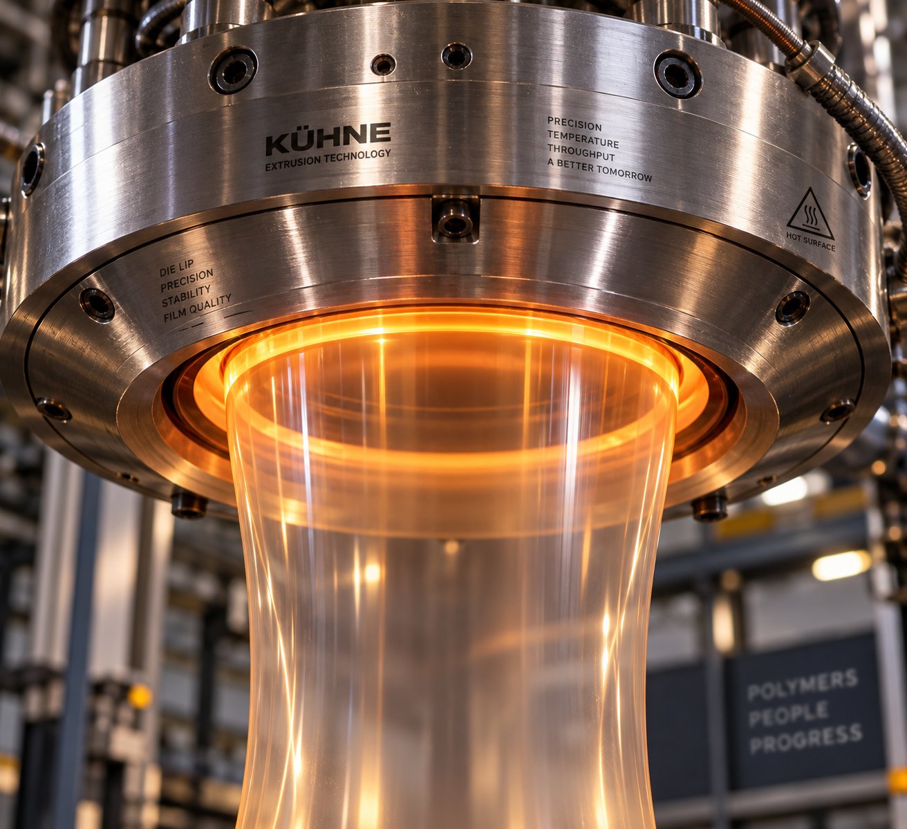
Bubble instability grabs your attention because it's dramatic — a dancing, breathing bubble is impossible to ignore. Die-related issues, by contrast, are quieter. They creep in gradually, building layer by invisible layer until streaks, specks, and thickness inconsistencies suddenly dominate your film. The source? Everything happening inside and at the exit of the die itself — buildup, degradation, uneven flow distribution, and the procedural choices made during every startup and shutdown cycle.
These extrusion-side defects are especially insidious because they often masquerade as resin issues. An operator sees streaks and suspects contamination in the raw material. A process engineer notices increasing gel counts and blames the supplier. In reality, the die and barrel are harboring the problem, and no resin change will fix what's accumulating on metal surfaces.
Die Lip Buildup — Causes and Purging Strategies
If you've ever noticed waxy, discolored deposits forming around the die exit during a long production run, you're looking at die lip buildup. This accumulation consists of low-molecular-weight polymer fractions, migrating additives (particularly slip agents and antioxidants), and oxidized material that gradually collects at the die lip where the melt meets ambient air. The deposits start thin and nearly invisible. Over hours or days of continuous running, they grow, harden, and eventually break loose — dragging across the film surface and leaving streaks, lines, or embedded specks.
Why does this happen? As molten polymer exits the die, volatile components at the melt surface oxidize on contact with air. Additives that are designed to bloom to the film surface — like erucamide slip agents — also migrate to the die lip, where they accumulate instead of distributing across the finished film. Higher melt temperatures accelerate this migration. Resins with elevated additive packages, or those processed above their recommended temperature windows, generate buildup significantly faster.
Effective blown film extrusion maintenance requires a proactive purging schedule rather than waiting for visible defects. Here are the key strategies:
- Scheduled purging intervals — Rather than purging only when defects appear, establish time-based intervals. For high-additive formulations, purging every 8 to 12 hours of continuous running prevents buildup from reaching critical levels.
- Use purpose-designed purging compounds — Production resins lack the detergency needed to dislodge baked-on deposits from metal surfaces. As Asaclean's extrusion specialists note, running regrind or virgin resin as a "purge" often creates hidden layers of material stacking inside the barrel and screw that eventually release as black specks or gels.
- Manual die lip cleaning — Between purge cycles, use brass scrapers (never steel — it scratches the die lip finish) to carefully remove visible buildup while the line is running. A damaged die lip surface accelerates future accumulation.
- Temperature management — Reducing die temperature by 5-10°F during extended runs can slow additive migration and oxidation at the die exit without significantly affecting film properties.
Die lip buildup is progressive — it's always accumulating, even when your film looks clean. The question isn't whether to purge, but how often to purge before buildup reaches the point where it creates visible defects.
Startup and Shutdown Procedures That Prevent Defects
Here's a scenario most blown film operators know well: you start the line Monday morning, and the first 30 to 60 minutes of production are riddled with black specks, dark streaks, and occasional gels. The film eventually cleans up, but you've already generated hundreds of pounds of scrap. Sound familiar? That contamination almost certainly originated from the previous shutdown — resin left stagnant in the barrel and die degraded overnight, and now it's flushing through your fresh production.
Improper shutdown leaves molten polymer sitting at elevated temperatures in dead spots within the screw flights, adapter channels, and die body. That stagnant melt oxidizes and carbonizes. An improper startup then pushes this degraded material directly into the product stream. The two procedures are inseparable — a clean startup depends entirely on a proper shutdown.
The following shutdown procedure, adapted from Davis-Standard's feedscrew and barrel maintenance guidelines, minimizes degradation between runs:
- Reduce extruder speed to approximately 75% of normal output while maintaining operating temperature.
- Introduce a thermally stable purge material or a base resin blended with an antioxidant master batch.
- Progressively lower barrel profile temperatures (to approximately 325°F for PE grades, 375°F for PP).
- Continue reducing speed to 25-40% of normal output as purge material displaces production resin.
- Drop barrel profile to a flat, reduced setpoint (approximately 280°F for PE, 350°F for PP).
- Monitor head pressure as barrel temperatures decrease.
- When extruder amps begin dropping, shut down the screw. For coextrusion lines, slow each extruder to 2 RPM until all are finished.
- Leave a small pool of material over the die lip to seal the land area against oxygen intrusion — this prevents carbonization on exposed die surfaces.
The restart sequence is equally critical. Bringing heat up too quickly risks thermally shocking stagnant material, while starting the screw before the polymer is fully molten creates enormous pressure spikes and pushes partially melted contamination downstream. Follow this recommended startup procedure:
- Set die temperature to a reduced initial setpoint (approximately 250°F) and soak for one hour to ensure uniform heat distribution.
- Gradually increase die temperature in stages (300°F, then 350°F, then production temperature), soaking 15 minutes at each stage.
- Bring adapters and screen changers online sequentially, following the same staged approach.
- Turn on extruder barrel heaters last, starting at a reduced profile (approximately 250°F) before stepping up to start temperature.
- Heat-soak the entire system for a minimum of 15 minutes at start temperature before engaging the screw.
- Idle the extruder at low RPM (~10 RPM) while monitoring pressure — watch for the purge material from shutdown to clear.
- Change the screen pack to production mesh once material runs clean.
- Clean and shim the die lip area, then set production temperatures and string the bubble.
The staged heat-soak approach serves two purposes. First, it minimizes the time stagnant polymer spends at elevated temperatures. Second, it maintains higher polymer viscosity during the initial purge phase — that higher viscosity generates greater scrubbing force against barrel and screw surfaces, helping dislodge residual material more effectively than a hot, low-viscosity melt would.
Degradation and Thermal History Problems
Every minute a polymer spends at elevated temperature adds to its thermal history — and that history is cumulative and irreversible. Degradation doesn't happen at a single threshold. It follows Arrhenius kinetics, which means the rate of degradation increases exponentially with temperature. A seemingly modest 10°C overshoot above the recommended processing window doesn't just increase degradation by a small margin — it can double or even triple the degradation rate, depending on the activation energy of the specific polymer.
What does degradation actually do to the polymer? That depends on the resin type. Polyethylene (especially HDPE) tends toward chain scission under thermal stress — long molecular chains break into shorter fragments, reducing melt viscosity, lowering mechanical strength, and potentially creating low-molecular-weight volatiles that cause odor and die lip buildup. Crosslinking-dominant degradation, more common in certain LLDPE grades and specialty polymers, produces the opposite effect: chains bond together into insoluble networks that show up as gels and hard specks in the film.
Both degradation pathways accelerate in the presence of oxygen. That's why the shutdown procedure's emphasis on sealing the die lip with a material bead is so important — it's a barrier against the oxygen that would otherwise catalyze carbonization on exposed metal surfaces overnight.
Practical implications for daily operations are straightforward but often overlooked. Avoid leaving the extruder at operating temperature during extended breaks without reducing setpoints or running purge material. Track your actual melt temperature (not just barrel setpoints) with an immersion thermocouple — shear heating from the screw can push actual melt temperature 20-40°F above your setpoint, silently accelerating degradation. And when troubleshooting increasing gel counts or darkening color in your film, look at the thermal history of the entire flow path — barrel, adapter, screen changer, and die body — before blaming the resin.
Temperature control within the die and barrel is something you can measure and adjust. But there's another category of variables that most operators don't think to measure at all — the ambient conditions surrounding the line itself, which shift with every season change, every opened bay door, and every humidity spike.
Environmental and Seasonal Factors Most Operators Overlook
Picture this: your blown film line ran flawlessly all winter. Same resin, same recipe, same crew. Then June arrives, and suddenly gauge variation creeps in, haze appears on your coextruded barrier film, and the bubble starts drifting slightly off-center during afternoon shifts. Nothing changed on the machine — so what happened?
The environment changed. And that single variable can silently destabilize a process that looked perfectly optimized on paper. Ambient temperature, humidity, and plant airflow are the most underestimated contributors to blown film problems, yet they're rarely the first thing operators investigate. Most troubleshooting instincts send you straight to the extruder controls or die settings. The environment doesn't even make the checklist — and that's exactly why these issues persist for days or weeks before someone identifies the real culprit.
Ambient Temperature and Seasonal Process Drift
The air surrounding your bubble is not just background — it's an active participant in the cooling process. As research into blown film cooling dynamics demonstrates, the temperature of cooling air directly governs heat transfer from the hot film surface, which in turn controls frost line height, bubble dimensions, and final film properties. When ambient temperature swings 20-30°F between winter and summer — or even 10-15°F between a cool morning and a hot afternoon — the entire thermal balance of your process shifts.
Here's the practical chain reaction. Warmer ambient air reduces the temperature differential between the cooling airflow and the molten bubble surface. That means less efficient heat removal, which pushes the frost line higher. A higher frost line creates a taller molten zone that is more susceptible to drafts and instabilities. You'll notice the bubble becoming slightly less stable, gauge variation increasing, and layflat width drifting as the bubble diameter fluctuates with the shifting freeze line. In winter, the opposite happens — colder air pulls the frost line down aggressively, potentially freezing the melt before it has fully oriented, leading to haze, brittleness, or reduced tear strength.
The fix isn't complicated, but it requires awareness. Seasonal process drift demands seasonal recipe adjustments. Air ring blower speeds, internal bubble cooling setpoints, and even melt temperature profiles may need to shift by a few percent between summer and winter baselines. Plants in climates with large diurnal temperature swings — desert regions, for instance, where mornings are cool and afternoons are scorching — may even need shift-to-shift parameter adjustments.
Humidity and Moisture-Sensitive Resin Problems
Humidity affects blown film in two distinct ways, and confusing them leads to misdiagnosis.
The first and most damaging pathway involves hygroscopic resins — polymers that actively absorb moisture from the surrounding air. In coextruded barrier films, nylon (PA) and EVOH are the primary offenders. These materials pull moisture directly into their pellet structure, and that absorbed water doesn't just sit on the surface where a hopper dryer can easily remove it. It penetrates into the polymer matrix, requiring sustained drying at precise temperatures to bring moisture content below critical thresholds — typically below 0.1% for nylon and below 0.05% for EVOH.
When insufficiently dried hygroscopic resin hits the extruder barrel, that trapped moisture flashes to steam at processing temperatures. The result? Splay marks (silver streaks radiating outward on the film surface), small embedded bubbles, haze, and in severe cases, foaming within the melt stream. These defects look alarming, but they trace back to a single variable: the resin's moisture content at the time it entered the extruder.
Here's the seasonal connection. Resin manufacturers provide standard drying times and temperatures based on assumed initial moisture levels. Those assumptions hold reasonably well in dry winter months. In summer — especially in humid regions — the actual moisture content of incoming pellets can be dramatically higher than the assumed baseline. A drying cycle that works perfectly in January may leave the resin under-dried in August. Operators need to verify actual moisture levels with an analyzer before processing, rather than relying on fixed drying schedules from the technical data sheet.
The second humidity pathway affects all resins, including non-hygroscopic polyethylene. High ambient humidity increases the moisture content of the cooling air itself. When that moist air contacts the hot bubble surface, condensation micro-droplets can form at or near the frost line, creating surface haze or pitting on the finished film. This effect is subtle and easily mistaken for a resin clarity issue or an additive migration problem.
Diagnosing Multiple Simultaneous Defects
Here's where environmental factors become truly deceptive. Unlike a worn screw or a contaminated resin lot — which typically produce a single, consistent defect — an environmental disturbance often triggers multiple symptoms simultaneously. And when an operator sees two or three different defects appearing at the same time, the instinct is to treat each one as a separate problem with a separate cause.
Imagine this real-world scenario: a shipping bay door opens on one side of the plant floor during a warm, humid afternoon. A gust of hot, moist air sweeps across the blown film tower. Within minutes, you observe gauge variation (the asymmetric airflow pushed the bubble off-center), haze on the film surface (humidity condensation at the frost line), and a slight frost line height increase (warmer ambient air reduced cooling efficiency). Three defects, one root cause. An operator who chases each symptom independently — adjusting the air ring for gauge, checking resin clarity for haze, and increasing blower speed for frost line — will over-correct in three different directions and potentially create new instabilities.
The diagnostic discipline is straightforward: always rule out environmental variables before touching machine settings. Use this checklist before making any process adjustments when defects appear unexpectedly:
- Check ambient temperature — Has it shifted more than 5°F from the conditions under which your process was last optimized? Log temperature readings at the beginning and middle of each shift.
- Check relative humidity — Is it above 60%? If running hygroscopic resins in coextrusion, verify actual pellet moisture content with an analyzer, not just drying time.
- Walk the perimeter — Are bay doors open? Are HVAC vents blowing directly toward the bubble? Has nearby equipment (ovens, laminators, compressors) been started or repositioned, radiating heat asymmetrically?
- Check for correlated timing — Did multiple defects appear at roughly the same time? If gauge variation, haze, and frost line shift all emerged within the same 15-minute window, suspect a single environmental event rather than multiple equipment failures.
- Review recent weather or facility changes — Seasonal transitions, roof repairs introducing new airflow paths, or changes to plant ventilation systems can all introduce process drift that doesn't show up on any machine alarm.
When multiple defects appear simultaneously, resist the urge to adjust multiple machine parameters at once. The most likely explanation is a single environmental root cause — find it first, and all the symptoms resolve together.
Installing a simple temperature and humidity data logger near the blown film tower — ideally at the same height as the air ring intake — gives you a continuous record that can be correlated against defect events. Over time, you'll build a seasonal map of your plant's environmental patterns and learn exactly when to pre-adjust your process before problems develop.
Environmental factors explain why the same machine, running the same recipe, produces different results at different times of year. But even within a single shift, the resin itself introduces another layer of variability — because LDPE, LLDPE, HDPE, and specialty polymers each respond to processing conditions in fundamentally different ways, demanding resin-specific troubleshooting approaches.
Resin-Specific Troubleshooting for Different Polymers
Every resin has a personality. LDPE forgives sloppy temperature control. LLDPE punishes you for ignoring melt strength. HDPE demands tight cooling precision or it warps and distorts. If you've been treating all polyethylenes the same on your blown film line, you've been troubleshooting with a blindfold on — because the defects each resin produces, and the corrective actions that actually work, are fundamentally different.
Understanding these resin-specific behaviors doesn't just help you fix problems faster. It helps you anticipate them before they start, especially when switching between grades or incorporating recycled content into your formulations.
LDPE vs LLDPE vs HDPE — Different Resins, Different Problems
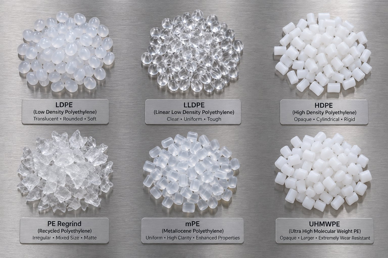
The molecular architecture of each polyethylene type dictates how it flows, stretches, cools, and ultimately fails during blown film extrusion. LDPE's extensive long-chain branching gives it high melt strength and excellent bubble stability — but that same branching makes it more susceptible to melt fracture at high shear rates. LLDPE, with its linear backbone and short-chain branches, delivers superior puncture and tear resistance in the finished film but runs with narrower processing windows and a persistent tendency toward draw resonance. HDPE sits at the other extreme: its high crystallinity demands precise cooling control, and even small deviations in frost line management produce warped or curled film.
Metallocene LLDPE (mLLDPE) deserves its own mention. These resins offer tighter molecular weight distributions, which translates to better optical clarity and more consistent mechanical properties — but that narrow distribution also means they're less forgiving of temperature fluctuations. You'll notice mLLDPE amplifying small process variations that conventional LLDPE would absorb without complaint.
Blends add another layer of complexity. Many converters mix LDPE into LLDPE-dominant recipes specifically to recover bubble stability, but improper blending ratios or inadequate mixing can create phase-separation artifacts that show up as haze or inconsistent gauge bands. The table below summarizes each resin's characteristic problem profile:
| Resin Type | Common Problems | Typical Processing Window Notes | Key Troubleshooting Differences |
|---|---|---|---|
| LDPE | Melt fracture at high output rates; die lip buildup from additive migration; lower stiffness leading to winder handling issues | Broad window (300-350°F melt); tolerant of temperature variation | Reduce shear rate or add processing aid for melt fracture; high melt strength makes bubble stability rarely the issue |
| LLDPE | Draw resonance; poor bubble stability; higher extruder motor load; neck-in at high TUR | Narrower window (350-420°F melt); sensitive to TUR and cooling rate | Blend 15-25% LDPE for stability; reduce TUR; increase cooling intensity to lower frost line; avoid over-stretching |
| HDPE | Warping and curling from uneven crystallization; high shrinkage; poor tear resistance in MD; melt fracture at moderate rates | Tight window (380-430°F melt); demands precise, uniform cooling | Focus on cooling symmetry and rate control; use oscillating die or rotating nip for gauge distribution; processing aids critical at higher output |
| mLLDPE | Amplified gauge variation from narrow MWD; sticky surface causing blocking; higher sensitivity to temperature swings | Similar to LLDPE but less tolerant of drift; requires stable melt temperature within ±3°F | Tighter temperature control essential; verify slip/antiblock additive levels; blend with LDPE if stability is insufficient |
| LDPE/LLDPE Blends | Phase separation causing haze at improper ratios; inconsistent gauge bands from poor mixing; variable mechanical properties | Intermediate between components; blend ratio determines effective window | Ensure adequate screw mixing; maintain consistent blend ratio; verify melt homogeneity before blaming die or cooling |
Recycled Content and Regrind Challenges
The pressure to incorporate post-consumer recycled (PCR) and post-industrial recycled (PIR) content into blown film is accelerating — driven by sustainability mandates and, in Europe, country-specific fees on virgin packaging material that make recycled content economically attractive. But recycled materials introduce a set of blown film problems that virgin resins simply don't present.
The core challenge is variability. Unlike virgin resin, which arrives with a tight specification sheet and consistent lot-to-lot properties, recycled content — especially PCR — carries an unpredictable mix of polymer types, additives, contaminants, and thermal histories. Here's what you'll encounter:
- Increased gel counts — Recycled material has already been through at least one melt-processing cycle, and often several. Each cycle adds thermal history, promoting crosslinking and degradation that manifests as gels in the finished film. As processing studies with LDPE regranulate confirm, differences in melt flow index between virgin HDPE and recycled LDPE fractions create flow irregularities that compound gel formation.
- Odor issues — PCR often carries residual odors from its previous life — food residues, cleaning products, or degradation byproducts. These volatiles release during extrusion and embed in the film, making it unsuitable for food-contact or scent-sensitive applications without additional venting or filtration.
- Color inconsistency — Mixed-source recycled streams rarely produce a consistent base color. Even with masterbatch addition, underlying color shifts between lots create visible variation in finished rolls.
- Reduced mechanical properties — Repeated thermal cycling shortens polymer chains and degrades tie molecules between crystalline regions. The result is lower tensile strength, reduced elongation at break, and diminished dart impact — properties that may fall below customer specifications at higher recycled-content percentages.
Efficient filtration becomes non-negotiable at elevated recycled-content levels. Continuous screen changers — as opposed to manual slide-plate designs that require line interruptions — allow operators to adjust screen fineness for each incoming batch without stopping production. RKW, a major European film producer, found that implementing continuous screen changers with backflush capability dramatically reduced machine downtimes and enabled consistent quality even with high proportions of recyclate. Pressure-controlled venting during screen changes is especially critical for blown film, since the thin, sensitive bubble reacts immediately to pressure fluctuations that would be trivial in thicker sheet or pipe extrusion.
Regrind — your own production scrap reintroduced into the process — presents a milder version of the same challenges. It's cleaner and more consistent than external PCR, but each pass through the extruder degrades the polymer incrementally. Most converters cap regrind addition at 10-20% for quality-critical applications, and the key discipline is tracking how many times a given batch of regrind has been reprocessed. Third-pass and fourth-pass regrind carries significantly more thermal history than first-pass material, and blending them indiscriminately creates unpredictable gel spikes.
When to Call the Resin Supplier
Not every blown film defect deserves a call to your supplier — but some absolutely do, and making that distinction efficiently saves time on both sides. Here's a practical decision framework:
- Call the supplier when a new defect appeared immediately after a resin lot change and persists even after verifying that all process parameters match the previous successful run.
- Call the supplier when melt index measurements on incoming material fall outside the grade specification — this indicates a manufacturing issue at the resin plant, not a processing problem on your line.
- Call the supplier when you observe unusual odor, discoloration, or pellet appearance (dust, fines, irregular shapes) that differ from previous lots of the same grade.
- Troubleshoot in-house first when the defect developed gradually over days or weeks with no resin lot change — this pattern points toward mechanical wear, die buildup, or environmental drift rather than incoming material.
- Troubleshoot in-house first when the same resin lot runs cleanly on a different line or at a different set of conditions — the resin is capable; your process needs adjustment.
- Troubleshoot in-house first when defects correlate with specific times of day, shifts, or environmental conditions — resin doesn't change behavior based on the clock.
- Involve both parties when you're increasing recycled content percentages and need guidance on maximum blend ratios, compatible additives, or revised processing windows for the specific virgin grade you're using as the base resin.
When you do contact the supplier, retain sealed samples of both the defective film and the suspect resin pellets, labeled with lot numbers and production timestamps. Suppliers can run gel permeation chromatography, ash content analysis, and additive assays on retained samples — but only if the samples are traceable and uncontaminated.
Specialty polymers push these resin-specific challenges even further. Blown thermoplastic polyurethane film, for example, demands a completely different troubleshooting mindset compared to polyolefins. TPU is hygroscopic, meaning it absorbs atmospheric moisture that must be removed through grade-specific drying before extrusion — supplier guides vary significantly, with some targeting moisture below 0.02% and others allowing up to 0.05%, depending on the exact TPU chemistry. Excess moisture causes hydrolysis during melt processing, silently reducing molecular weight and melt strength even when visual defects aren't obvious. TPU is also prone to thermal degradation in stagnant flow zones, making dead-spot-free die and adapter designs essential. Gels in TPU film can originate from crosslinked degradation, incompatible additives, or poorly dispersed masterbatch — and diagnosing the source requires isolating each variable systematically rather than applying polyolefin-based assumptions. If you're running TPU on a blown film line designed for PE, expect to rethink your drying infrastructure, temperature profiles, screw design, and purging procedures from the ground up.
Resin behavior and material quality set the stage for what's possible on your blown film line. But even perfectly formulated, defect-free film can be ruined after it leaves the bubble — by the very equipment designed to handle, treat, and wind it into finished rolls.
Downstream Equipment Defects From Nip to Winder
You've optimized your melt temperature, stabilized the bubble, and confirmed that the film leaving the frost line is clean, consistent, and on-gauge. Then you pull a finished roll off the winder — and find wrinkles pressed into the surface, layers stuck together, or the entire roll shifted sideways like a leaning tower. What went wrong?
The answer is downstream. Everything between the collapsing frame and the finished roll — nip rolls, idler rollers, corona treaters, slitters, and winders — has the potential to introduce defects into otherwise perfect film. Yet most operators instinctively look upstream when roll quality suffers. They adjust die temperatures or air ring settings when the real culprit is a misaligned nip roller or an incorrect taper tension profile. This blind spot is one of the most persistent and costly categories of blown film problems in any converting operation.
Wrinkles and Web Handling Failures
Wrinkles are the single most common downstream complaint, and they're deceptively complex. Not all wrinkles are created equal — and recognizing the pattern tells you exactly where to look.
Machine-direction (MD) wrinkles run parallel to the web travel direction. They're typically triggered by roller wobble, uneven traction, or tension oscillation between nip stations. Diagonal or baggy wrinkles suggest uneven tension across the web width, poor spreading, or a web that isn't centered as it enters the winder. Creases — sharp, permanent fold lines — are usually wrinkles that got compressed through a nip roller and became locked into the film structure.
Here's the critical insight most troubleshooting guides miss: a wrinkle you see on the finished roll may not have been created at the winder. As Wilson Machinery's winding analysis explains, you need to split the line into tension zones — each nip creates a boundary — and work backward from the winder until you find the first zone where the web is flat and stable. If the web already shows instability upstream of a particular nip, the winder is merely recording the defect, not creating it.
A practical zone-by-zone approach:
- Start at the winder and observe the web just before it contacts the roll.
- Move upstream through each nip station and idler section.
- When the web becomes flat and wrinkle-free before a specific nip, the problem source is downstream of that point.
- If the web is already unstable coming out of the collapsing frame, the root cause is likely gauge variation or bubble instability — not downstream equipment.
Common downstream causes of wrinkles include nip rollers that aren't parallel across the web width, nip pressure set too high for the film gauge (compressing a minor wave into a permanent crease), contamination or surface damage on roller faces creating localized traction differences, and web guiding systems that allow lateral drift into edge contacts. A quick diagnostic: reduce nip pressure slightly and run a short trial. If hard creases soften into gentle waves, you've confirmed the nip isn't the root cause — it's the point where an existing issue becomes permanent.
Tension management is equally critical, and both extremes fail. Excessive tension stretches the web unevenly across its width, amplifying minor thickness differences into traction imbalances that create wrinkles. Insufficient tension allows the web to flutter, wander, or entrain air between layers, producing soft rolls that deform during storage or shipping. The target isn't a single tension number — it's the setpoint that keeps the web flat, centered, and stable at your production speed.
Blocking and Telescoping in Finished Rolls
Blocking — where adjacent film layers stick together and resist unwinding — is a defect that doesn't reveal itself until the customer tries to use the roll. It's a function of both formulation and winding conditions, and blaming one while ignoring the other leads to recurring failures.
On the formulation side, slip and antiblock additives are your primary defense. Slip agents (typically erucamide or oleamide) migrate to the film surface to reduce layer-to-layer friction. Antiblock additives (usually silica or talc particles) create microscopic surface roughness that introduces air gaps between layers, preventing intimate contact. When either additive is under-dosed — or when processing temperatures are high enough to degrade them before they can migrate — blocking risk increases dramatically.
On the winding side, excessive tension compresses layers together with enough force to overwhelm additive protection. As converting expert Neal Michal notes, blocking in wound rolls is common on tacky films and is often intensified by rolls wound too tight or at elevated temperature. His recommended countermeasures include reducing wound-on tension, lowering web temperature before the winding station, and increasing surface topography to introduce air into the roll structure. If blocking occurs only near the core, the localized high interlayer pressure in that region is the culprit — winding on larger cores or implementing taper tension profiles that reduce pressure near the core can resolve it.
Telescoping — where layers shift laterally so the roll face looks stepped or angled — shares an intimate relationship with gauge bands. Even minor gauge variation, perhaps ±3-5% across the web width, creates hard and soft lanes within the wound roll. The hard lanes (thicker regions) bear disproportionate interlayer pressure, while adjacent soft lanes (thinner regions) carry less pressure and lower torque capacity. When the roll encounters any lateral force — during transport, unwinding acceleration, or simply under its own weight — those low-pressure lanes slip, and the roll telescopes.
This is why gauge variation and telescoping must be addressed together. Tightening winder tension to "hold" a telescoping roll only masks the symptom while increasing blocking risk. The real fix starts upstream with improved gauge uniformity — through die bolt adjustment, oscillating die rotation, or correcting the air ring asymmetry causing the gauge band in the first place. Downstream, verify that web guiding systems track consistently and that cores and chucks are in good condition, since worn chucks allow the core to shift during winding.
Corona Treatment and Surface Energy Issues
Corona treatment raises the surface energy of polyethylene film so that inks, adhesives, and coatings can wet and bond to it. Untreated PE film has a surface energy around 31-33 dynes/cm — too low for most printing and laminating processes. Corona treatment oxidizes the surface, raising energy to 38-44 dynes/cm or higher, depending on the application requirements.
When corona treatment causes downstream problems, it typically falls into one of three categories. First, insufficient treatment — the film leaves the treater below the target dyne level, causing ink adhesion failures or delamination in laminated structures. This traces back to electrode wear, incorrect air gap settings, insufficient power density, or running the web faster than the treater can handle. Second, over-treatment — excessive power oxidizes and embrittles the film surface, creating a chalky or powdery texture that paradoxically reduces adhesion and can cause haze. Third, backside treatment — corona discharge wraps around to the untreated side of the web, raising its surface energy unintentionally. This causes blocking (the now-tacky treated backside sticks to the front surface in the roll) and interferes with heat sealing performance.
The difference between cast vs blown stretch wrap behavior through downstream handling is worth noting here. Cast stretch film, produced through a chill-roll process, has a smoother, glossier surface and inherently different cling characteristics compared to blown stretch film. Blown stretch wrap's higher surface roughness and greater elastic memory make it cling through mechanical interlocking rather than surface tack, which means it handles differently through nip stations and winders. Cast films are more prone to blocking because their smoother surfaces allow greater intimate contact between layers, while blown films are stiffer and more resistant to telescoping but harder to wind without entrapping air due to their surface texture. Operators transitioning between cast and blown products on shared downstream equipment need to adjust tension profiles, nip pressures, and lay-on roller settings accordingly — the same winder recipe won't work for both.
| Downstream Defect | Equipment Source | Root Cause | Corrective Action |
|---|---|---|---|
| MD Wrinkles | Nip rolls, idler rollers | Roller wobble, runout, or tension oscillation between stations | Check bearing condition and roller runout; stabilize tension control; verify roller parallelism across web width |
| Diagonal/Baggy Wrinkles | Web guiding system, spreader rolls | Uneven cross-web tension, web tracking drift, or poor spreading | Re-align guide system; verify spreader roll function; center the web before winding |
| Creases (Permanent Folds) | Nip rolls | Excessive nip pressure compressing a minor wrinkle into a permanent fold | Reduce nip pressure; verify nip parallelism; ensure web enters nip without angle or skew |
| Blocking (Layers Sticking) | Winder | Excessive winding tension, insufficient slip/antiblock additives, high web temperature at winding | Reduce wound-on tension; verify additive levels; cool web before winder; use taper tension to reduce core-area pressure |
| Telescoping (Lateral Layer Shift) | Winder, web guide | Gauge bands creating uneven interlayer pressure; poor web tracking; worn cores or chucks | Improve upstream gauge uniformity; verify web guiding; inspect core and chuck condition; avoid sudden tension changes |
| Insufficient Corona Treatment | Corona treater | Electrode wear, incorrect air gap, insufficient power, excessive web speed | Replace worn electrodes; adjust air gap per manufacturer spec; increase power or reduce line speed; verify dyne level with test pens |
| Over-Treatment / Backside Treatment | Corona treater | Excessive power density; incorrect web path allowing discharge wrap-around | Reduce power to target dyne level; verify web wrap angle isolates backside from discharge zone; check ground roll condition |
| Soft or Floppy Rolls | Winder | Insufficient tension, air entrainment between layers, no lay-on pressure | Increase winding tension incrementally; engage lay-on roller to expel trapped air; verify taper tension profile builds firm core |
If your film looks clean and on-gauge at the frost line but finished rolls show wrinkles, blocking, or telescoping, resist the urge to adjust the die or extruder. The defect source is almost certainly downstream — trace it zone by zone from the winder back to the collapsing frame before changing upstream parameters.
Downstream equipment may be the last link in the chain, but its condition degrades over time just like every other component on the line. Bearings wear, roller surfaces score, tension controllers drift out of calibration, and corona electrodes erode — all silently, until defects cross the threshold of visibility. That gradual, invisible deterioration is precisely why preventive maintenance deserves as much structured attention as real-time troubleshooting, and why the most effective blown film operations treat maintenance schedules as a quality system rather than an afterthought.
Preventive Maintenance That Stops Problems Before They Start
Every defect discussed so far — gels, gauge bands, wrinkles, blocking — has a corrective action. But corrective action is reactive by definition. You've already made scrap, already lost time, and already consumed engineering hours chasing a root cause. The most profitable blown film operations flip this equation entirely, investing in structured preventive maintenance that catches mechanical degradation weeks or months before it manifests as a film defect. The payoff isn't hypothetical. As Swallow Machinery's maintenance analysis emphasizes, unplanned downtime in blown film extrusion isn't just inconvenient — it's a costly disruption where minor issues quickly escalate into major production failures when routine upkeep is neglected.
Think of it this way: you wouldn't run a car 50,000 miles without an oil change and then blame the gasoline when the engine starts knocking. Yet operators routinely blame resin quality or die settings for problems that trace directly back to worn mechanical components — components that nobody inspected on schedule.
Screw and Barrel Wear — The Hidden Problem Source
If there's a single maintenance blind spot that causes more misdiagnosed blown film problems than any other, it's screw and barrel wear. The degradation is so gradual that it's practically invisible. Output drops by a fraction of a percent per week. Melt temperature uniformity drifts slightly. Gel counts creep up by a handful per square meter per month. None of these incremental changes triggers an alarm or a line stoppage — they just slowly erode your quality baseline until one day you realize the line can't hold gauge, gels are out of spec, and your motor load has climbed 15% above where it was six months ago.
Here's what's physically happening. The screw flights and barrel bore are precision-machined to maintain tight clearances — typically 0.003 to 0.005 inches per side for standard polyethylene extruders. As these metal surfaces wear, the clearance widens. Wider clearance means more polymer leaks backward over the flights (known as backflow or pressure flow loss), which directly reduces output efficiency and creates stagnant material pockets that degrade into gels and black specks. Simultaneously, worn flights deliver less compressive and shear mixing energy to the polymer, meaning the melt becomes less homogeneous. Un-melts increase. Temperature consistency suffers because the screw is no longer generating the intended shear heat profile.
The insidious part? Operators compensate instinctively. They bump up screw speed to restore output. They raise barrel temperatures to compensate for reduced shear heating. They increase screen pack mesh to catch the extra gels. Each compensation masks the underlying wear — until the compensations are maxed out and the line simply can't make good film anymore, regardless of settings.
Measuring wear requires pulling the screw periodically and checking flight OD dimensions against original specifications, while bore gauging the barrel ID at multiple points along its length. When clearances exceed roughly twice the original specification, replacement becomes cost-effective because the energy waste and quality losses from continued operation outweigh the component cost. When that point arrives, selecting the right replacement isn't a commodity decision. Purpose-built film extrusion barrels with appropriate metallurgy — bimetallic liners for abrasion resistance when running filled or recycled materials, nitrided surfaces for standard polyolefin processing — and tight dimensional tolerances are essential for restoring consistent melt quality and output stability. Suppliers like NANHAIYA, who manufacture custom and replacement single screw barrels specifically designed for film, pipe, sheet, and recycling extrusion applications, can match barrel specifications to your exact process requirements rather than forcing a generic fit.
Preventive Maintenance Schedule for Blown Film Lines
A blown trading account on maintenance eventually bankrupts your production quality. The table below consolidates inspection intervals, warning signs, and required actions across every critical component of a blown film line. Treat it as a living document — adjust intervals based on your specific resin types, run hours, and historical failure patterns.
| Component | Inspection Interval | Warning Signs of Wear | Action Required |
|---|---|---|---|
| Screw flights | Every 4,000–6,000 operating hours (or annually) | Declining output at constant RPM; rising motor amps; increasing melt temperature variation; higher gel counts | Pull screw and measure flight OD at feed, transition, and metering zones; compare against original spec; rebuild or replace if clearance exceeds 2x original |
| Barrel bore | Every 4,000–6,000 operating hours (concurrent with screw inspection) | Same output and quality symptoms as screw wear; visible scoring or grooves when screw is pulled | Bore-gauge at multiple axial positions; check for ovality; replace barrel if wear exceeds tolerance — ensure replacement matches process metallurgy requirements |
| Die body and flow channels | Quarterly full strip-down and cleaning | Persistent die lines that don't respond to lip adjustment; increasing gel or speck counts after startup; uneven melt distribution across the die circumference | Disassemble, clean all flow surfaces, inspect for scoring or plating wear; polish mandrel and body; replace damaged components |
| Die lip surfaces | Daily visual inspection; manual cleaning every 8–12 hours during high-additive runs | Visible waxy or discolored buildup at the die exit; streaks appearing on film surface | Clean with brass scrapers (never steel); schedule purge compound flush; reduce die temperature 5–10°F to slow accumulation |
| Air ring and IBC system | Monthly inspection; quarterly deep cleaning | Asymmetric frost line; gauge variation that rotates around the bubble; reduced cooling efficiency at constant blower speed | Clean air ring lips and internal passages; verify radial airflow uniformity with anemometer; check IBC valves and air lines for leaks |
| Temperature controllers and heater bands | Monthly calibration check; semi-annual full calibration | Zone temperatures that drift from setpoint; slow response to setpoint changes; one zone consistently over- or under-shooting | Calibrate controllers against reference thermocouple; check heater band resistance and contact; replace failed heaters immediately — a single dead zone creates a cold spot that generates un-melts |
| Pressure transducers | Semi-annual calibration; replace every 2–3 years regardless of condition | Pressure readings that don't correlate with observed melt behavior; erratic pressure swings with no process change | Calibrate against deadweight tester; inspect diaphragm for damage or polymer contamination; replace if readings are unstable |
| Cooling water system (chill rolls, barrel cooling) | Monthly water quality check; quarterly heat exchanger inspection | Rising barrel or melt temperatures at constant settings; reduced chill roll cooling capacity; scale buildup visible in sight glasses | Test water for hardness, pH, and biological contamination; flush and descale heat exchangers; verify flow rates match equipment specifications |
| Screen changer | Inspect seals and hydraulics monthly; rebuild per manufacturer interval | Polymer leaking past screen plate seals; slow or inconsistent screen changes; pressure spikes during changeover | Replace seals; verify hydraulic pressure and speed settings; clean breaker plate bores |
| Gearbox | Oil analysis every 6 months; full inspection annually | Unusual noise or vibration; rising oil temperature; metal particles in oil sample | Change oil per manufacturer schedule; inspect gears and bearings; address misalignment if vibration analysis indicates it |
A few implementation notes make this schedule practical rather than aspirational. First, create a logbook — digital or physical — that records every inspection, measurement, and replacement with dates. This historical record transforms from administrative overhead into your most powerful diagnostic tool. When gel counts suddenly increase six months from now, you can cross-reference against the last screw measurement, the last die cleaning, and the last heater replacement to narrow the root cause in minutes instead of hours.
Second, use OEM-quality or purpose-engineered replacement parts. A generic barrel that's close to spec but not matched to your specific extrusion process — in terms of compression ratio, L/D ratio, alloy composition, and bore finish — introduces a new variable into a system where precision matters. This is especially critical for film extrusion, where melt homogeneity requirements are far tighter than in thicker-wall applications like pipe or profile.
Modern Process Control and Sensor Monitoring
Preventive maintenance catches problems that are developing. Modern process control catches problems that are happening right now — and in some cases, predicts them before they start.
The most impactful technology for blown film quality is automated gauge control. Continuous-scan thickness gauges — using beta, gamma, or infrared sensors — measure film thickness around the entire bubble circumference in real time. The control system then adjusts individual die bolt heaters (or air ring segments, depending on the system architecture) to correct localized thick or thin spots automatically, without operator intervention. The Maguire + Syncro extrusion control platform exemplifies this integrated approach, using real-time consumption data to control line speed and haul-off while the Syntrol supervisory system synchronizes extruder temperature, pressure, air ring, IBC, and thickness gauge from a single touchscreen.
Oscillating or rotating dies address a fundamental limitation of manual gauge adjustment: even with automated die bolt control, small gauge variations tied to die body geometry repeat at the same circumferential position on every revolution. By slowly rotating the die relative to the haul-off, these fixed-position variations get distributed around the roll rather than stacking into gauge bands. The result is dramatically improved roll quality and reduced telescoping — a downstream defect that, as the previous chapter established, traces directly back to gauge uniformity.
Sensor-based monitoring extends beyond thickness. Inline melt pressure and temperature sensors positioned at the adapter and die inlet provide continuous data streams that reveal trends invisible to periodic manual checks. A slow, steady pressure increase over weeks suggests screen blinding or increasing flow restriction from die buildup — prompting maintenance before visible defects appear. A gradual rise in melt temperature at constant barrel setpoints signals increasing screw wear and shear heat generation — exactly the kind of hidden deterioration that preventive screw inspections are designed to catch.
Thermal imaging cameras, deployed during quarterly inspections, identify overheating bearings, failing heater bands, and heat leaks in cooling systems that manual touch checks miss. Some facilities mount permanent thermal sensors at critical points and feed them into plant-wide monitoring dashboards that alert maintenance teams to anomalies in real time.
The best preventive maintenance program combines scheduled physical inspections with continuous sensor monitoring — human eyes catch what sensors miss, and sensors catch what happens between inspections.
Together, structured maintenance schedules and intelligent process control create a system where blown film problems are detected at the earliest possible stage — ideally before they produce a single meter of defective film. But even the best-maintained, best-monitored line will eventually encounter a problem that doesn't fit neatly into a maintenance checklist or a sensor alarm. When that happens, the critical question shifts from "what do I inspect?" to "who do I call — and how do I systematically diagnose something that doesn't follow the usual patterns?"
When to Escalate and How to Diagnose Intermittent Issues
Some blown film problems announce themselves clearly. A worn screw produces a steady decline in output. A contaminated resin lot delivers gels from the first meter. A misaligned air ring creates a gauge band that shows up in every roll. These are frustrating, but they're solvable — because the symptoms are consistent, repeatable, and traceable. The truly maddening problems are the ones that vanish the moment you start looking for them. Intermittent defects that appear for twenty minutes, disappear for an hour, and return without warning. Transient instabilities that correlate with nothing obvious. Issues that three experienced operators describe three different ways.
These are the blown opportunities in troubleshooting — the defects that slip through because they don't fit a predictable pattern. And they're also the ones most likely to be dismissed, worked around, or blamed on the wrong variable. Solving them requires both a clear escalation framework and a disciplined diagnostic method.
Troubleshoot In-House or Call for Help — A Decision Framework
When a problem persists beyond initial adjustments, the instinct is often to keep tweaking — one more temperature change, one more speed adjustment, one more screen pack swap. But there's a point where continued in-house experimentation costs more than bringing in outside expertise. The challenge is recognizing that point before you've wasted a full shift chasing the wrong cause.
Use these criteria as a decision tree to determine where the problem most likely originates and who should address it:
- The defect appeared immediately after a resin lot change — Contact the resin supplier. Retain sealed pellet and film samples with lot numbers. Request melt index verification and additive assay against the grade specification. If the supplier confirms the material is in-spec, the issue may be a subtle rheological shift within specification that still affects your specific process window — discuss processing guidance for that lot.
- The defect developed gradually over days or weeks with no material change — Troubleshoot in-house, focusing on mechanical wear. Inspect screw flight dimensions, barrel bore clearances, die surfaces, and screen condition. Check temperature controller calibration and heater band continuity. This pattern almost always points to progressive component degradation rather than a sudden external change.
- The defect correlates with time of day, shift changes, or weather conditions — Investigate environmental factors first. Log ambient temperature, humidity, and plant airflow conditions alongside defect occurrences. Resin doesn't change behavior based on the clock — but cooling air temperature, humidity-driven moisture absorption, and drafts from open bay doors absolutely do.
- The defect persists after exhausting in-house process adjustments across multiple shifts — Contact the equipment manufacturer. Die flow imbalances, internal cooling system design limitations, or control system faults may require OEM-level diagnostics and tooling that your maintenance team doesn't have on-site.
- The defect appears on one line but not another running the same resin and recipe — The problem is line-specific, not material-related. Compare mechanical condition, die geometry, and cooling system configuration between lines. When screw and barrel wear is identified as the root cause, sourcing precision-engineered replacement components becomes critical. A supplier like NANHAIYA, offering custom single screw barrels designed specifically for film, pipe, sheet, and recycling extrusion applications, can match barrel metallurgy and dimensional specifications to your exact process rather than forcing a generic substitution that introduces new variables.
- You're scaling up recycled content or switching to a specialty polymer — Involve both the resin supplier and your own process engineering team simultaneously. These transitions often require revised processing windows, additive adjustments, and potentially equipment modifications that benefit from collaborative expertise.
The underlying principle is simple: match the investigation to the pattern. Sudden onset after a material change points externally. Gradual onset with no material change points internally. Correlated timing points environmentally. When you can't determine the pattern at all — that's when intermittent diagnostics become essential.
Diagnosing Intermittent and Transient Problems
Intermittent defects are the mind blown picture of extrusion troubleshooting — they defy expectations, resist simple explanations, and frustrate even veteran operators. A gel spike that lasts fifteen minutes and then clears. A gauge band that appears every third roll. A haze event that shows up only on Tuesday afternoons. These patterns seem random, but randomness is almost never the actual explanation. Something changed — the challenge is figuring out what, and when.
The fundamental mistake operators make with intermittent problems is adjusting process parameters during the event. When a transient defect appears and you simultaneously change melt temperature, screw speed, and air ring settings, you've introduced three new variables into an already unclear situation. Even if the defect disappears, you don't know whether your adjustments fixed it or whether it would have resolved on its own. Worse, your adjustments may have masked the root cause while creating a new baseline that produces different problems later. Structured troubleshooting methodologies developed through decades of industrial experience emphasize isolating variables and observing system response — not reacting to every fluctuation with multiple simultaneous changes.
Follow this systematic diagnostic sequence when facing intermittent or transient issues:
- Document the event immediately. Record the exact time, duration, defect type, and severity. Photograph the defect on the film and note which position on the web (left edge, center, right edge, random) it occupies. Do this every time the defect appears — even if it seems identical to the last occurrence.
- Freeze all process parameters. Resist the urge to adjust. Let the defect run its course while you observe and record. Note the extruder RPM, melt pressure, melt temperature, barrel zone temperatures, air ring blower speed, IBC pressure, and nip roll speed at the moment the defect begins and when it ends.
- Cross-reference against external variables. Check the resin lot number currently running. Note ambient temperature and humidity. Walk the plant perimeter — are doors open? Has adjacent equipment started or stopped? Did a new operator begin a shift? Did the material handling system switch hoppers or blenders?
- Review upstream process data logs. Modern extruders record melt pressure, motor load, and zone temperatures continuously. Pull the data for the time window surrounding the defect event and look for any parameter that deviated from its baseline — even briefly. A two-second pressure spike from a partially blocked screen can release a slug of degraded material that shows up as a transient gel burst minutes later downstream.
- Check for periodicity. After documenting three or more events, look for repeating intervals. A defect that recurs every 45 minutes may correlate with a screw rotation cycle pushing accumulated material past a worn flight. A defect appearing every time a particular hopper empties and refills may indicate contamination in the material handling system. Periodicity is the single most powerful clue in intermittent troubleshooting because it links the defect to a specific mechanical or process cycle.
- Isolate one variable at a time. Once you have a hypothesis, test it by changing only the suspected variable while holding everything else constant. If you suspect a resin lot, run a controlled trial with a known-good lot under identical conditions. If you suspect ambient temperature, compare defect frequency between morning and afternoon shifts using the same material and settings.
- Confirm by reproduction. The strongest proof of root cause is deliberate reproduction. If your hypothesis is correct, you should be able to intentionally trigger the defect by reintroducing the suspected variable — and eliminate it by removing that variable. Until you can do both, your diagnosis remains a hypothesis.
One underappreciated source of transient problems is the interaction between equipment wear and specific processing conditions. A screw with marginal flight wear may perform acceptably at moderate RPM but produce surging and gel bursts when pushed to high output — because the wider clearance only becomes problematic when pressure differentials across the flights increase at higher speeds. The defect appears intermittent because it only manifests when the operator pushes the line hard, and it disappears when speed drops back to normal. This kind of conditional failure is invisible to any inspection that doesn't include running the equipment across its full operating range.
Building a Continuous Improvement Culture on the Production Floor
Individual troubleshooting events solve individual problems. But the real competitive advantage belongs to operations that accumulate troubleshooting knowledge systematically — turning each incident into institutional memory rather than letting it evaporate when the shift ends.
The single most powerful tool for this isn't sophisticated software or expensive monitoring equipment. It's a defect log. Every blown film operation should maintain a running record — digital spreadsheet, shared database, or even a dedicated binder at the operator station — with the following fields for each incident:
- Date and time of occurrence
- Defect type and severity (with photo or physical sample)
- Resin grade, lot number, and blend ratio
- All key process parameters at the time of the event (melt temperature, screw RPM, line speed, BUR, die temperature, air ring settings)
- Ambient temperature and humidity
- Any recent changes — material lot, operator, equipment maintenance, environmental conditions
- Root cause determination (confirmed or suspected)
- Corrective action taken and result
The value of this log compounds over time. After six months, patterns emerge that no single operator could recognize from memory alone. You might discover that gel count spikes correlate with a specific resin supplier lot prefix. Or that gauge variation events cluster around the third week of each month — when seasonal temperature swings hit a critical threshold at your facility. Or that a particular extruder consistently develops melt temperature drift approximately 5,000 hours after its last screw inspection, giving you a predictive maintenance trigger that's specific to your line rather than borrowed from a generic schedule.
Pattern recognition across logged incidents is the most powerful long-term troubleshooting tool any blown film operation can build. Individual expertise solves today's problem — systematic documentation solves tomorrow's before it happens.
This approach transforms troubleshooting from a reactive skill held by a few experienced individuals into an organizational capability that survives shift changes, retirements, and personnel turnover. New operators don't start from zero — they start from a documented history of every problem the line has encountered and every solution that worked.
It also shifts the conversation from blame to learning. When defect events are logged with process data rather than operator names, the focus stays on system-level causes rather than individual mistakes. That cultural shift — from "who messed up" to "what changed" — is what separates operations that keep solving the same problems from operations that eliminate them permanently.
Blown film extrusion will always involve complexity. Polymers behave differently under stress. Equipment wears. Environments shift. Resin lots vary. But complexity doesn't have to mean unpredictability. With accurate defect identification, structured diagnostic methods, disciplined maintenance, and a commitment to logging what you learn, every problem your bubble shows you becomes a data point — and enough data points reveal the patterns that keep your line running clean, stable, and profitable.
Frequently Asked Questions About Blown Film Problems
1. What are the most common blown film extrusion defects?
The most common blown film extrusion defects include gels (smooth, translucent bumps caused by degraded or crosslinked material), fish eyes (circular halos around an opaque nucleus from un-dispersed additives or moisture), melt fracture (widespread surface roughness from excessive shear at the die exit), black specks (carbonized resin from thermal degradation), and gauge variation (uneven film thickness across the web). Each defect points to a different root cause, so accurate visual identification is essential before selecting a corrective action. Operators should collect labeled physical film samples of each defect type for training and quick comparison during production.
2. How do you fix bubble instability in blown film extrusion?
Fixing bubble instability starts with identifying the specific instability mode. Helical instability, which appears as a spiraling corkscrew motion, is corrected by profiling the air ring for uniform radial airflow and eliminating environmental drafts. Draw resonance, a rhythmic pulsation of bubble diameter, requires reducing the take-up ratio (TUR), lowering melt temperature to boost melt strength, or blending 15-25% LDPE into LLDPE-dominant formulations. Bubble breathing, characterized by irregular expansion and contraction, typically traces to IBC system leaks or inconsistent extruder output. Always check BUR and TUR together rather than in isolation, since adjusting one without the other can simply shift the instability to a different direction.
3. What causes die lines and die lip buildup in blown film?
Die lip buildup forms when low-molecular-weight polymer fractions, migrating additives such as slip agents, and oxidized material accumulate at the die exit where molten resin contacts ambient air. Over time, these deposits harden and eventually break loose, dragging across the film surface to create streaks and embedded specks. Die lines, by contrast, are narrow linear streaks caused by damage or contamination on the die lip surface itself. Prevention requires scheduled purging every 8-12 hours during high-additive runs, manual cleaning with brass scrapers, and reducing die temperature by 5-10 degrees Fahrenheit to slow additive migration. Using purpose-designed purge compounds rather than production resin ensures baked-on deposits are actually dislodged.
4. How does ambient temperature and humidity affect blown film quality?
Ambient temperature directly impacts cooling efficiency. Warmer summer air reduces the temperature differential between cooling airflow and the molten bubble, pushing the frost line higher and creating a taller, less stable melt zone prone to gauge variation and drift. Colder winter air pulls the frost line down aggressively, potentially causing haze or brittleness. Humidity affects film through two pathways: hygroscopic resins like nylon and EVOH absorb atmospheric moisture that flashes to steam during extrusion, causing splay marks and bubbles, while high-humidity cooling air can form condensation micro-droplets at the frost line, creating surface haze on any resin type. Seasonal recipe adjustments to blower speeds, IBC setpoints, and melt temperatures are necessary to compensate for these environmental shifts.
5. When should you replace the screw and barrel on a blown film extruder?
Screw and barrel replacement becomes cost-effective when clearances exceed roughly twice the original specification, typically measured during inspections every 4,000-6,000 operating hours. Warning signs include declining output at constant RPM, rising motor amperage, increasing melt temperature variation, and gradually climbing gel counts. The degradation is so gradual that operators often compensate by increasing speed or barrel temperatures, masking the underlying wear until the line can no longer produce acceptable film. When replacement is needed, purpose-built film extrusion barrels with appropriate metallurgy and tight dimensional tolerances are critical. Suppliers like NANHAIYA (nhyscrews.com) manufacture custom single screw barrels specifically designed for film extrusion applications, matching barrel specifications to exact process requirements for restored melt quality and output stability.
Written by
Nanhaiya Technical Team
Zhoushan Nanhaiya Plastic Machinery Co., Ltd.
The Nanhaiya technical team supports screw and barrel manufacturing projects through application review, technical communication, custom manufacturing coordination, and production and quality control.
Discuss Your Application
Related Articles
More insights on screw barrel technology and plastics processing.
WPC Decking Extrusion Line Decoded: From Raw Resin To Finished Board
Oct 23, 2026
Learn how a WPC decking extrusion line works — from raw material compounding and extruder selection to process parameters, troubleshooting defects, and line layout planning.
Read Article
Your Extruder Feeding Instability Isn't Random — Here's Why
Oct 22, 2026
Extruder feeding instability causes surging output and scrap. Learn the 6 root causes, polymer-specific fixes, wear diagnostics, and preventive protocols.
Read Article
Your PP Pipe Extrusion Machine Is Only As Good As Your PP Grade
Oct 22, 2026
Learn how PP pipe extrusion machines differ from generic lines. Covers PP grade selection, key components, process steps, specs, maintenance, and buying tips.
Read ArticleLooking for something else?
Search by material, symptom or product and jump straight to the relevant page.
These are navigation suggestions based on keyword matching — not a quotation, not a delivery commitment, and not a substitute for engineering review. Final specification is confirmed by our engineers against your drawings and processed material.
Need help with screw barrel selection?
Share your machine model, processed material and application. Our team can help with pricing and technical support.