

What a WPC Decking Extrusion Line Does and Why It Matters
Imagine turning a heap of recycled plastic pellets and sawdust into a perfectly shaped, weather-resistant decking board — all in a single, continuous production run. That is exactly what a WPC decking extrusion line accomplishes, and understanding how it works is the first step toward making informed equipment and process decisions.
What Is a WPC Decking Extrusion Line
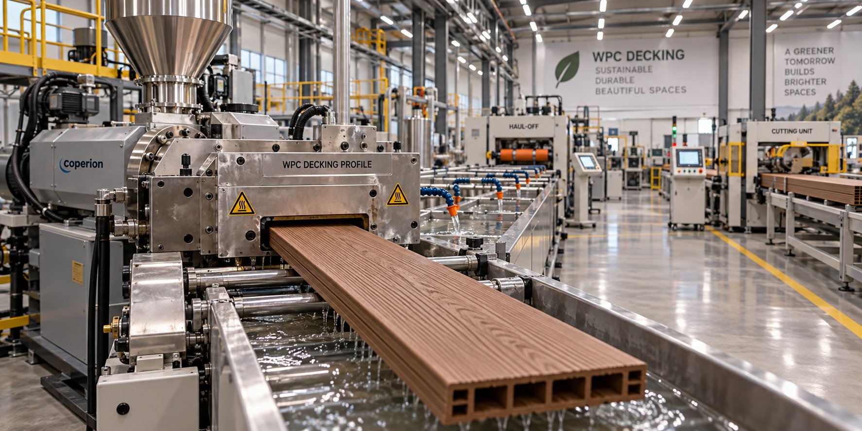
A WPC decking extrusion line is an integrated production system that compounds, melts, shapes, calibrates, cools, and cuts wood-plastic composite material into finished decking boards ready for installation.
At its core, the wood plastic composite decking production line transforms a carefully engineered blend of three components: a thermoplastic polymer matrix (typically PE, PP, or PVC), wood fiber filler (often reclaimed sawdust or wood flour), and a suite of performance additives. These additives — coupling agents, lubricants, UV stabilizers, and colorants — ensure the raw blend behaves predictably under heat and pressure, and that the finished board holds up outdoors for years.
The WPC decking board manufacturing process follows a clear sequence. Raw materials enter a compounding stage, travel through an extruder where heat and mechanical shear create a uniform melt, pass through a precision die that forms the profile shape, and then move through calibration, cooling, and cutting stations. Each station plays a distinct role you'll explore in the sections ahead.
Why WPC Decking Demand Drives Equipment Investment
Several market forces make this equipment category increasingly attractive. WPC decking outlasts natural timber in moisture-heavy environments, requires virtually no staining or sealing, and appeals to sustainability-minded buyers because it can incorporate recycled polymers and reclaimed wood fiber. These advantages have pushed global WPC decking consumption steadily upward, drawing new manufacturers into the space.
One decision every new producer faces early is the choice between a hollow vs solid WPC decking profile. Hollow profiles use less material per linear meter and are lighter, but they demand more complex die geometry and precise vacuum calibration to maintain consistent wall thickness. Solid profiles are simpler to extrude yet heavier and more material-intensive. Die design, calibration technique, and downstream cooling all shift depending on which profile type you choose — a theme that will surface repeatedly throughout this guide.
The real performance of any line, however, begins long before the extruder starts turning. It starts with how raw materials are prepared, blended, and fed — a critical upstream stage that deserves far more attention than it typically receives.
Raw Material Compounding and Formulation Fundamentals
Every defect you see on a finished WPC decking board — rough surfaces, color streaks, inconsistent density — can almost always be traced back to something that went wrong before the material ever reached the extruder. The WPC raw material compounding process is where product quality is won or lost, yet it is the stage most overlooked when specifying a production line.
Hot-Cold Mixer Operation and Material Preparation
Picture this: you dump wood flour straight into an extruder without any pre-treatment. The moisture trapped inside those fibers (commonly 5-15% in raw wood flour) would flash into steam the moment it hit the melt zone, creating voids, foaming, and a profile no one wants to install on a deck. That is why every serious WPC decking extrusion line starts with a hot-cold mixer system.
The high-speed hot mixer spins the blend at roughly 800-1200 RPM, using frictional heat to raise the material temperature to approximately 110-130 degrees Celsius. At this temperature range, two critical things happen simultaneously. First, residual moisture in the wood fiber is driven off — you need wood flour humidity below 1% for stable extrusion. Second, the coupling agents in the formulation become activated, beginning to bridge the natural incompatibility between hydrophilic wood particles and the hydrophobic polymer matrix.
Once the hot mix cycle completes, the blend is immediately discharged into a cold mixer. This lower-speed, jacketed vessel circulates chilled water through its walls to bring the compound temperature below the polymer's softening point — preventing premature agglomeration or gelation. The result is a free-flowing, dry, homogeneous blend ready to feed directly into an extruder or into a pelletizing step.
What goes into that blend matters enormously. Each additive category serves a distinct function in the wood fiber coupling agent formulation for WPC:
- Coupling agents (e.g., MAPP for polyolefin matrices, silanes for PVC) — chemically link the wood fiber surface to the polymer, improving dispersion and boosting flexural strength by up to 1.5 to 2 times compared to uncompatibilized blends.
- Lubricants — external types (zinc stearates, PE waxes) prevent the compound from sticking to barrel walls and screw surfaces, while internal types reduce melt viscosity for smoother flow through the die.
- UV stabilizers (HALS, benzophenone derivatives) — protect the finished board from photodegradation, which can cause color fading and surface embrittlement during outdoor exposure.
- Colorants and pigments — provide the desired wood-tone appearance and can also function as supplementary light stabilizers.
- Biocides (e.g., zinc borate) — guard against fungal and mold attack, particularly important in formulations with higher wood fiber content.
Typical additive loading for a PE-matrix WPC might include 30-60% wood flour, 2-5% coupling agent, 3-8% lubricant, and smaller fractions of stabilizers and pigments — though every formulation is fine-tuned to the target product and processing equipment.
Pelletizing Versus Direct Extrusion of Dry-Blended Material
After the hot-cold mixer delivers a ready compound, producers face a pivotal decision: feed that dry blend directly into the profile extruder, or run it through a compounding extruder first to create uniform pellets? The answer depends on your polymer matrix, production volume, and tolerance for process variability.
WPC pelletizing vs direct extrusion dry blend is not simply a cost question — it is fundamentally about melt consistency. When you pelletize, every granule has already been fully compounded: the polymer has encapsulated the wood fibers, the coupling agent has reacted, and the blend has been homogenized under controlled shear and temperature. The profile extruder then receives a predictable, uniform feed that produces stable melt pressure and consistent board dimensions.
Direct dry-blend feeding skips that intermediate step, saving the capital cost of a compounding extruder and eliminating one thermal cycle. However, the profile extruder must now perform both the compounding and shaping functions simultaneously, which places greater demands on screw design and barrel temperature control.
Here is where polymer chemistry tips the scales:
| Dimension | Pelletized Feedstock | Direct Dry-Blend Feeding |
|---|---|---|
| Material consistency | High — pre-compounded and homogenized | Moderate — depends on mixer quality and extruder screw design |
| Capital investment | Higher — requires a separate compounding/pelletizing extruder | Lower — hot-cold mixer feeds directly to the profile extruder |
| Throughput stability | Very stable melt pressure and output rate | Can fluctuate if feed consistency varies |
| Best suited polymer matrix | PE and PP (polyolefin WPC) | PVC-based WPC |
| Why | PE/PP require full melt blending for fiber encapsulation; pelletizing ensures complete coupling agent reaction | PVC undergoes unique gelation behavior on twin-screw extruders, allowing it to compound effectively from dry blend in a single pass |
| Thermal exposure | Two heat cycles (pelletizing + profile extrusion) — slight risk of wood fiber degradation if temperatures are poorly managed | Single heat cycle — lower cumulative thermal history on the wood fiber |
PVC-based WPC works well with direct dry-blend feeding because, unlike polyolefins, PVC behaves more like a rubber-like solid during processing rather than forming a true melt. Intermeshing twin-screw extruders transport PVC dry blend through cavities largely independent of barrel friction, providing consistent output without needing a pre-pelletized feedstock. PE and PP formulations, by contrast, rely on achieving a genuine melt state for proper fiber wetting, making the pelletizing step a much safer route to consistent board quality.
Formulation choices also ripple forward into the extruder itself. A higher wood fiber percentage — say 60% rather than 40% — increases compound viscosity and abrasion, which demands a more aggressive screw compression ratio and harder barrel metallurgy. Larger wood particle sizes change the way the material flows in the screw channels, while even small increases in residual moisture content can cause venting problems that show up as surface blisters on the finished board. These upstream variables set the stage for everything the extruder, die, and downstream equipment must handle — a connection explored in the sections that follow.
Mono-Extrusion Versus Co-Extrusion Technology Compared
The way raw material is compounded and fed determines melt quality — but the type of extrusion architecture you choose determines what kind of product that melt becomes. A WPC decking extrusion line can be configured as either a mono-extrusion system or a co-extrusion system, and this single decision shapes everything from equipment cost and board performance to the market segment you can realistically compete in. Yet the engineering rationale behind each approach is rarely explained in clear, practical terms. Here is how WPC decking co-extrusion vs mono-extrusion actually breaks down.
How Mono-Extrusion Lines Produce Standard WPC Decking
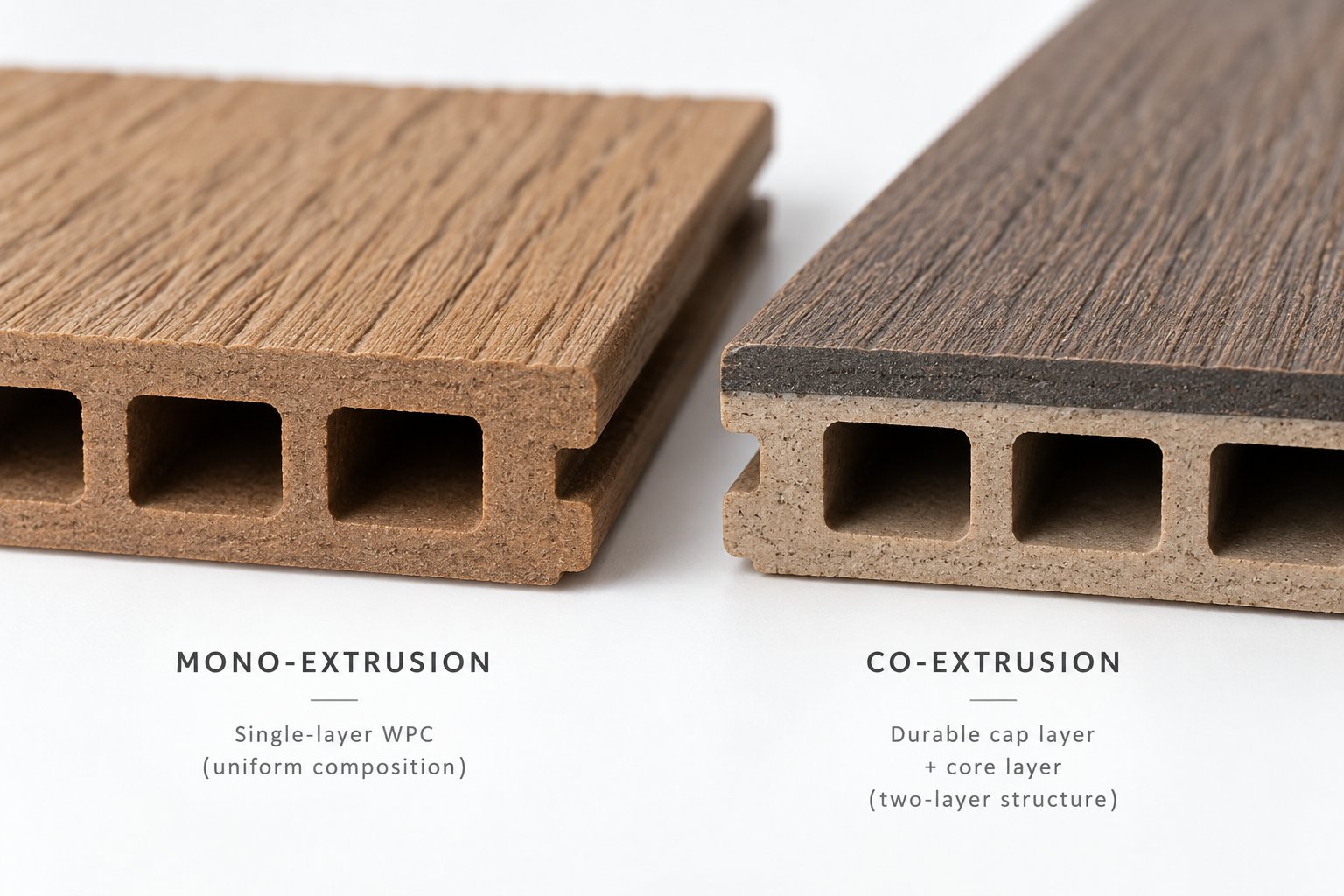
A mono-extrusion line is the more straightforward configuration. One extruder melts and pushes a single, homogeneous WPC compound through a profile die, producing a board where the core and the surface are made of the same material. Every cross-sectional layer — from the center of a hollow chamber wall to the outermost surface the homeowner walks on — shares identical composition, color, and mechanical properties.
This simplicity carries real advantages. Equipment costs are lower because you need only one extruder, one set of feed controls, and a single-channel die. Process setup is faster since there is no secondary melt stream to balance against the core. Operators with basic extrusion experience can manage the line without specialized co-extrusion training.
When does mono-extrusion make sense? Consider these scenarios:
- Cost-sensitive projects — builders and distributors targeting budget-tier decking where purchase price drives the buying decision.
- Uniform-color products — applications where a consistent, single-tone appearance is acceptable or even preferred.
- Moderate exposure environments — covered patios, screened porches, or regions with lower UV intensity where extreme fade resistance is not critical.
The trade-off is that the exposed WPC surface has no additional protection. Wood fibers at the board surface are directly subjected to UV radiation, foot traffic abrasion, and stain penetration. Over time, this can lead to noticeable fading, surface erosion, and susceptibility to stubborn stains — limitations that drove the industry toward a more engineered alternative.
When and Why Co-Extrusion Adds a Protective Cap Layer
Imagine wrapping a standard WPC board in a thin, tough polymer shell — fused permanently during the extrusion process, not painted or glued on after the fact. That is essentially what a co-extrusion cap layer WPC decking line achieves.
Co-extrusion uses a secondary extruder to melt a separate, highly engineered polymer and feed it through a dedicated flow channel in a specially designed co-extrusion die. This cap material merges with the WPC core melt just before the die exit, forming a continuous bond as both layers cool together. The result is a board with a cost-effective, high-fill WPC substrate protected by a thin outer skin — typically 0.3 to 0.8 mm thick — engineered specifically for surface performance.
The cap layer polymer is chosen for properties the WPC core alone cannot deliver. Common cap materials include:
- ASA (Acrylonitrile Styrene Acrylate) — the ASA cap layer wood plastic composite decking option is popular because ASA offers outstanding UV stability and color retention without requiring heavy stabilizer loading in the core.
- HDPE blends — modified with UV stabilizers and pigments, used when the cap must bond chemically to a polyolefin-based WPC core.
- Modified PVC compounds — paired with PVC-based WPC cores for material compatibility, offering good scratch hardness and weathering resistance.
The performance gains are substantial. Co-extruded boards deliver wear and scratch resistance more than five times higher than standard mono-extruded WPC, along with significantly improved stain resistance — the solid outer layer blocks penetration of colored and oily liquids. Color consistency improves dramatically as well, since the cap polymer accepts pigments more uniformly than a wood-fiber-filled compound.
From an equipment perspective, co-extrusion die design for WPC profiles adds meaningful complexity. The die must incorporate separate flow channels for core and cap materials, merging them at precisely controlled pressures and temperatures. A mismatch causes delamination, uneven cap thickness, or surface waviness. The secondary extruder also requires its own temperature profile, feed system, and screw configuration tuned to the cap polymer's rheology — a very different processing challenge than handling a wood-fiber-filled core compound.
Cost-Quality Trade-Offs Between the Two Approaches
Choosing between these architectures is not about which one is "better" — it is about matching equipment investment to your target market and pricing strategy. The comparison below lays out the key dimensions side by side:
| Dimension | Mono-Extrusion | Co-Extrusion |
|---|---|---|
| Equipment complexity | Single extruder, single-channel die | Primary + secondary extruder, multi-channel co-extrusion die, additional temperature controls |
| Capital cost | Lower — fewer machines, simpler die tooling | Higher — secondary extruder, co-extrusion die, and more sophisticated control systems add 30-50% to line cost |
| Material cost per linear meter | Lower — one compound for the entire cross-section | Moderately higher — cap polymer (ASA, HDPE, or modified PVC) is more expensive per kilogram than the WPC core blend |
| UV performance | Moderate — relies on stabilizers blended into the WPC compound; fading visible within 2-3 years of outdoor exposure | Superior — engineered cap layer provides dedicated UV barrier; color retention extends well beyond 10 years |
| Scratch resistance | Moderate — exposed wood fibers at the surface are vulnerable to abrasion | High — cap layer hardness can exceed Shore D 65, resisting foot traffic and furniture movement |
| Stain resistance | Low to moderate — porous WPC surface absorbs colored liquids | High — non-porous cap prevents liquid penetration, making cleaning simple |
| Color uniformity | Acceptable — wood fiber distribution can cause subtle streaking | Excellent — cap polymer accepts pigment uniformly without fiber interference |
| Target market segment | Budget to mid-range residential, commercial utility applications | Mid-range to premium residential, high-traffic commercial, hospitality, and marine environments |
You'll notice the pattern: co-extrusion costs more at every stage — in equipment, in tooling, and in material — but it unlocks a product tier with higher margins and longer warranty claims. Many manufacturers start with a mono-extrusion line to enter the market at lower risk, then add a co-extrusion setup once they have secured premium distribution channels that justify the investment.
The choice between mono-extrusion and co-extrusion is ultimately a business decision guided by engineering trade-offs — match the line architecture to the performance tier your target customer is willing to pay for.
Whichever path you take, the extruder, die, calibration system, and downstream equipment must be configured to suit. A co-extrusion die with dual flow channels demands tighter tolerances and harder steels than a single-channel mono-extrusion die, while the calibration table must accommodate a composite profile with different thermal contraction rates in core and cap layers. These equipment-level details are where line performance is truly defined — and they deserve a station-by-station examination.
Key Equipment Stations From Extruder to Cutting System
A WPC decking extrusion line is not a single machine — it is a coordinated chain of specialized stations, each one engineered to perform a precise function at exactly the right moment. Miss any link, and the board that comes off the end will show it. Yet most equipment discussions treat these stations as a simple list of names. What matters more is understanding why each station exists, what technology choices it presents, and how those choices ripple forward through the rest of the line.
Here is a complete WPC decking extrusion line equipment list, walked through in the order material actually travels — from molten compound to a finished, cut board ready for stacking.
Extruder Types and Screw-Barrel Configurations
The extruder is the heart of the entire line. It receives the compounded material — whether pelletized granules or dry-blended powder — and converts it into a homogeneous, pressurized melt that can be forced through a die. For WPC decking, two twin-screw architectures dominate the market, and the choice between them depends primarily on the polymer matrix in your formulation.
Conical twin screw extruders are the standard workhorse for PVC-based WPC decking. The two intermeshing screws taper from a larger diameter at the feed end to a smaller one at the discharge, creating a natural compression ratio — typically 3:1 to 4:1 — without relying on aggressive kneading elements. This geometry is especially effective for densifying the low-bulk-density wood-polymer blends common in WPC. Because a conical twin screw extruder for WPC decking runs at relatively low peripheral speeds (often 15-25 RPM), it generates less frictional heat, which protects temperature-sensitive PVC compounds and wood fibers from degradation. The compact, tapering barrel also means a shorter overall machine length, which can matter in tight factory layouts.
A parallel twin screw extruder for wood plastic composite production takes a different approach. Both screws maintain a constant diameter along the full barrel length, with compression and mixing achieved through changes in screw pitch, channel depth, and modular kneading block configurations. This design gives engineers much greater freedom to configure independent mixing, melting, and venting zones along a longer L/D ratio — typically 28:1 to 36:1 compared to the conical's 22:1 to 28:1. The result is superior melt homogeneity and higher throughput potential, which is why parallel machines are the preferred choice for PE and PP-based WPC lines running at volumes above 400-500 kg/h.
Regardless of type, WPC extrusion places extraordinary demands on screw-barrel metallurgy. Wood flour contains silica particles that act like fine sandpaper against metal surfaces. Standard nitrided steel screws and barrels can wear unacceptably fast under these conditions. That is why most WPC-focused extruders use bimetallic barrel linings — a centrifugally cast inner layer of hard alloy (often iron-boron or tungsten carbide-based) bonded to a conventional steel outer shell — combined with hardened screw flight tips. Compression ratio, flight depth, and the L/D ratio are all tuned specifically for the high-fill-ratio, high-viscosity nature of WPC compounds. A barrel and screw set optimized for rigid PVC window profiles, for example, will struggle with a 55% wood flour WPC formulation because the channel geometry and wear protection are simply not designed for that level of abrasion and resistance to flow.
Die, Calibration, Cooling, and Cutting Systems
Everything downstream of the extruder exists for one purpose: to transform the pressurized, hot melt into a dimensionally stable, cool, finished board. Each station handles one critical phase of that transformation. Here is the production-line sequence from die exit to stacking:
- Profile die — The die shapes the melt into the target cross-section, whether a solid rectangular plank or a hollow multi-chambered profile. For hollow WPC decking, the die incorporates internal mandrels that create the void channels, requiring precise flow balancing so that each wall section receives equal melt pressure. Die land length and lip temperature are critical — too short a land and the melt has not stabilized; too cool a lip and you get surface roughness. Dies for WPC profiles are typically made from hardened tool steel and polished to mirror finish to reduce drag on the high-viscosity melt.
- Vacuum calibration table — Immediately after leaving the die, the still-soft profile enters a vacuum calibration table for WPC profile extrusion. Dry calibration with vacuum sizing is the most common approach for decking boards. The profile is drawn through a precision-machined metal sleeve while vacuum pressure (typically -0.02 to -0.06 MPa) pulls the outer surfaces outward against the sleeve walls. This locks the external dimensions — width, height, and wall thickness — while the profile is still pliable enough to conform. Gaskets and water spray within the calibrator simultaneously begin removing surface heat. Alignment between the die exit and the calibrator inlet is critical: even a 1-2 mm misalignment can cause uneven wall thickness or surface drag marks.
- Cooling tanks — After calibration sets the profile geometry, additional cooling tanks reduce the board temperature to near ambient. Two approaches are common. Spray cooling directs water jets onto the profile surface, providing controlled, gradual heat removal that minimizes internal thermal stress — especially important for thick solid profiles where aggressive cooling can cause warping. Immersion cooling submerges the profile entirely in a water bath, which extracts heat faster and suits thinner-walled hollow profiles where internal stress is less of a concern. Many lines use a combination: spray cooling in the first tank for controlled solidification, followed by immersion tanks for final temperature reduction.
- Haul-off unit — The haul-off pulls the cooled profile through the entire downstream section at a precisely controlled speed. Wall thickness depends on the relationship between extruder output and haul-off speed — run the haul-off too fast and the profile stretches thin; too slow and material accumulates, distorting the cross-section. Caterpillar-type haul-offs are the standard for WPC decking because their continuous rubber belt or pad contact surface distributes pulling force evenly across the board's width, preventing localized deformation. Roller-type haul-offs can work for simpler profiles but may leave contact marks on softer WPC surfaces.
- Cutting system — The continuous profile must be cut to sellable board lengths. A flying saw — a circular blade mounted on a carriage that travels with the moving profile during the cut — is the most common choice for WPC decking because it allows cutting without stopping the line, maintaining a continuous production rhythm. Guillotine cutters offer a simpler, lower-cost alternative for slower lines but produce a less precise end cut and briefly interrupt profile movement. For high-output lines, dust extraction at the cutting station is essential because WPC sawing generates fine composite particles.
- Stacking and off-loading table — Cut boards are received onto a run-out table or automated stacking system that organizes them for inspection, packaging, or palletizing. While this station seems straightforward, board handling immediately after cutting matters — WPC boards retain residual internal stress, and improper stacking while still slightly warm can cause bowing that only becomes apparent later.
You'll notice a pattern across these stations: each one is not just performing a mechanical function in isolation. The die's flow balance determines what the calibrator must correct for. The calibrator's cooling rate influences how much work remains for the cooling tanks. The haul-off speed must synchronize with the extruder's output and the cutter's cycle time. As one reference puts it, many quality problems that appear at the finished product are misdiagnosed as extruder problems when the real cause lies in downstream misalignment, speed mismatch, or inadequate cooling length.
Getting every station right is the engineering challenge. Keeping every station running consistently over thousands of production hours is the operational challenge — and that is where the conversation shifts to process parameters and the critical interactions between them.
Process Parameters and How They Interact
Having every equipment station perfectly specified means little if the numbers running through them are wrong. A well-built line with poorly set parameters will produce warped, rough, or dimensionally inconsistent boards just as reliably as a cheaply built line — sometimes faster. WPC extrusion process parameter optimization is not about memorizing a single recipe; it is about understanding how each setting influences the others, and why changing one variable in isolation almost always creates a new problem somewhere else.
Most WPC extrusion defects trace back not to a single wrong setting, but to a mismatch between two or more interdependent parameters — screw speed versus feed rate, die temperature versus haul-off speed, or cooling intensity versus profile wall thickness. Effective optimization means managing these relationships, not chasing individual numbers.
Temperature Profiles Across Barrel Zones and Die
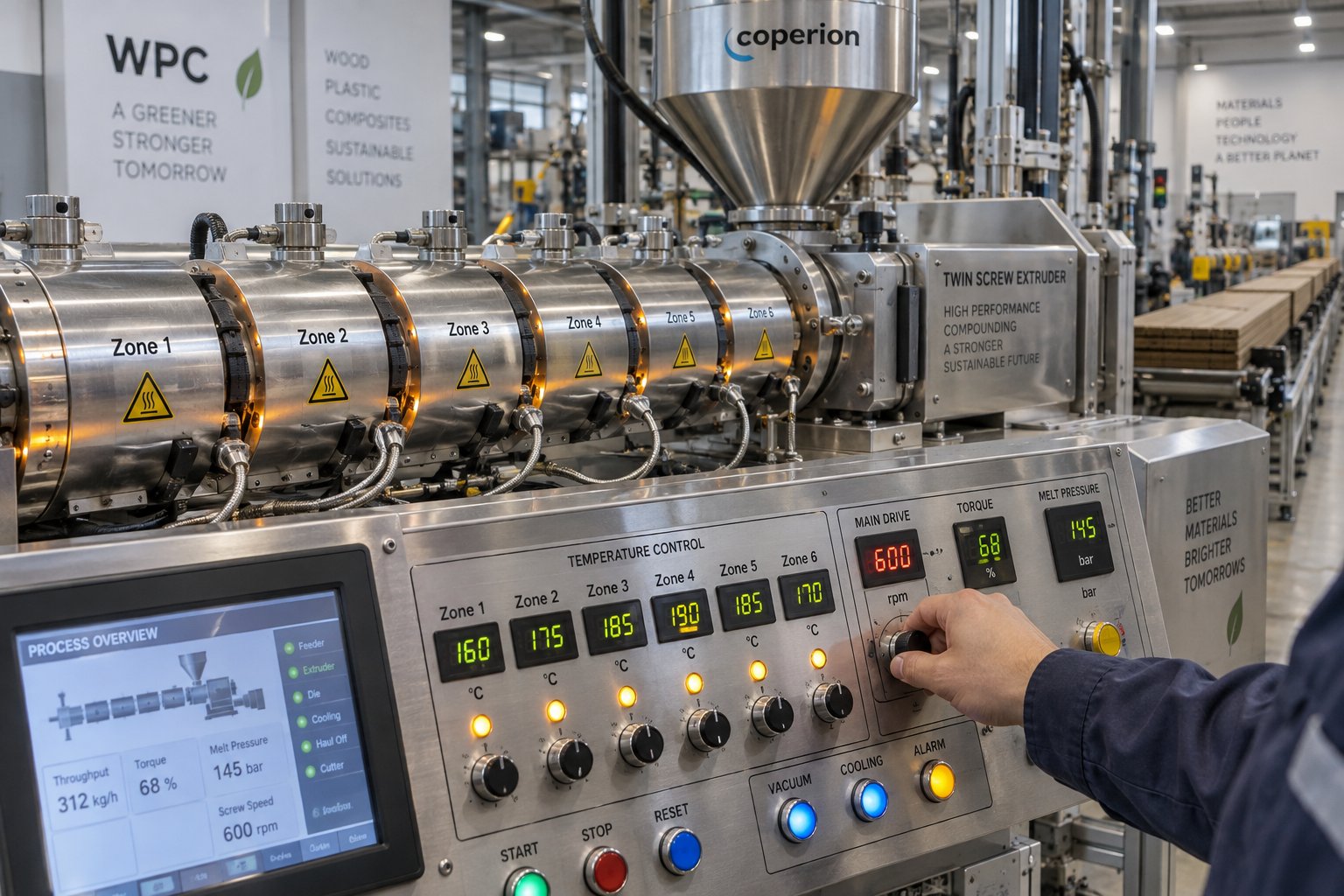
Think of the barrel as a series of thermal chapters, each one doing different work on the compound as it moves from hopper to die. The WPC extrusion temperature profile settings follow a staged logic that mirrors what the material needs at each point in its journey.
In the feed zone, barrel temperatures are kept relatively low — often 140-155 degrees Celsius for PE/PP-based WPC, or 150-160 degrees Celsius for PVC-based formulations. Why? You want the material to be conveyed forward by the screw flights without prematurely melting into a slippery mass that loses grip against the barrel wall. Too much heat here starves the downstream zones of material.
Through the compression and melting zones, temperatures climb progressively. PE/PP-based WPC compounds typically see barrel zone temperatures for wood plastic composite processing in the range of 160-180 degrees Celsius, while PVC-based WPC stays lower — generally 155-170 degrees Celsius — because PVC is thermally sensitive and begins to degrade above roughly 185-190 degrees Celsius. The difference matters enormously. Running a PVC-WPC formula at polyolefin temperatures risks rapid thermal decomposition, releasing HCl gas that corrodes metal surfaces and produces visibly degraded, discolored boards.
The metering zone stabilizes the melt at a consistent temperature and pressure before it enters the die. Here, temperature is often held flat or slightly reduced to manage melt viscosity without introducing thermal gradients.
The die temperature itself is arguably the most surface-critical setting on the entire line. Too cold, and the melt drags against the die walls, producing a rough, matte, or shark-skinned surface. Too hot, and the profile exits soft and sags before reaching the calibrator. For most WPC decking profiles, die temperatures run 5-15 degrees Celsius above the metering zone, carefully tuned to achieve a smooth, glossy surface without sacrificing dimensional control.
These ranges are general principles, not universal recipes. Exact values shift depending on the specific formulation, wood fiber loading percentage, extruder geometry, and even ambient factory temperature. Two lines running the same compound in different facilities will often settle on different optimal profiles.
How Screw Speed, Feed Rate, and Haul-Off Interact
Temperature gets the most attention, but the dynamic trio of screw speed, feed rate, and haul-off speed is where real process control lives — and where most operators struggle. These three parameters are locked in a constant balancing act.
Screw speed directly controls throughput and shear. Increasing RPM pushes more material through the barrel per unit time, but also generates more frictional (shear) heat inside the melt. For WPC, this is a double-edged sword. Excessive shear degrades wood fibers — breaking them into shorter fragments that weaken the finished board and darken the color. Research on polymer extrusion optimization confirms that process output is fundamentally shaped by the interaction between screw speed and thermal conditions, not by either variable alone. In practice, WPC lines run at lower screw speeds than unfilled polymer lines — often 8-20 RPM for conical twins and 15-35 RPM for parallel twins — precisely to protect fiber integrity.
Feed rate must match the screw's conveyance capacity. Overfeed the hopper and material backs up, creating pressure spikes and inconsistent output. Underfeed, and the screw channels run partially empty — a condition called starving — which can actually improve mixing in some cases but reduces throughput and changes the melt's thermal history unpredictably.
The relationship between screw speed and haul-off speed for WPC decking is where dimensional accuracy lives. If the haul-off pulls faster than the extruder delivers material, the profile stretches — wall thickness drops, hollow chambers deform, and internal stresses build in that cause post-production warping. Pull too slowly, and material bunches at the calibrator entrance, distorting the cross-section. The target is a neutral or very slight tension — just enough to keep the profile tracking straight through the calibration and cooling line.
Cooling water temperature adds another layer. For PE and PP-based WPC, cooling rate directly affects crystallization behavior. Rapid cooling with very cold water creates a highly stressed skin with a different crystal structure than the slower-cooling core — a gradient that can cause delayed warping or cracking. Gradual cooling allows more uniform crystallization and better dimensional stability. Studies on semicrystalline polymer extrusion show that processing conditions — including shear history and cooling rate — have a dramatic effect on crystallization kinetics, reinforcing why cooling is not just a "make it cold" step but a genuine process control variable. PVC-based WPC, being amorphous, is less sensitive to cooling rate but still requires uniform temperature reduction to avoid residual stress.
The table below organizes every critical parameter by extrusion stage, showing what it controls and what happens when it drifts out of range:
| Extrusion Stage | Key Parameter | Function | Effect of Deviation |
|---|---|---|---|
| Feeding | Feed rate (kg/h) | Controls volume of material entering the screw channels | Overfeed causes pressure surges and blockages; underfeed causes starving, reduced output, and inconsistent melt |
| Melting / Plasticizing | Barrel zone temperatures (degrees C) | Stage heat input to progressively soften and melt the compound | Too high degrades PVC or burns wood fibers; too low leaves unmelted particles visible in the profile |
| Melting / Plasticizing | Screw speed (RPM) | Drives material forward and generates shear-based heat and mixing | Too fast degrades wood fibers and overheats the melt; too slow reduces throughput and may cause poor homogeneity |
| Metering | Melt pressure (MPa) | Indicates flow resistance and die filling consistency | Unstable pressure causes surging — visible as periodic thickness variation in the finished board |
| Die | Die lip temperature (degrees C) | Controls melt viscosity at the shaping point and surface finish quality | Too cold causes shark-skinning or rough surface; too hot causes profile sag and loss of shape before calibration |
| Calibration | Vacuum level (-MPa) | Pulls profile surfaces outward against the sizing sleeve to set external dimensions | Too strong distorts the profile or collapses thin walls; too weak allows the profile to shrink away from target dimensions |
| Cooling | Water temperature (degrees C) | Controls rate of heat extraction and, for PE/PP WPC, crystallization behavior | Too cold creates thermal shock, surface cracking, or internal stress gradients; too warm leaves the profile soft at the haul-off |
| Haul-off | Haul-off speed (m/min) | Pulls profile through downstream equipment and controls final wall thickness | Too fast stretches and thins the profile; too slow causes material buildup at the calibrator entrance |
Each row in that table connects to every other row. Raise screw speed without adjusting haul-off speed and you get a thicker board. Lower die temperature without compensating barrel heat and you create uneven flow. Crank cooling water down to near-freezing without adjusting line speed and internal stresses silently build into boards that warp a week after shipping. The operators who produce the most consistent WPC decking are the ones who treat these parameters as a system — adjusting in small increments, changing one variable at a time, and waiting for the line to stabilize before evaluating results.
Even with perfect parameter control, though, there is one factor that gradually undermines every setting on the line: mechanical wear. Wood fiber-filled compounds are relentless abrasives, and the screws and barrels that maintain all of this precise temperature, pressure, and flow control slowly lose their geometry with every production hour — a reality that demands its own focused discussion.
Screw and Barrel Wear Management for WPC Lines
Every parameter discussed so far — barrel temperatures, screw speed, melt pressure, haul-off tension — depends on tight mechanical tolerances inside the extruder. But here is the uncomfortable truth: the moment a WPC decking extrusion line starts running, those tolerances begin to erode. Wood fiber-filled compounds are among the most abrasive materials any extruder will ever process, and the screws and barrels that maintain precise melt control are slowly losing their geometry with every kilogram of compound pushed through. Understanding why this happens, what it costs you in product quality, and how to manage it systematically is one of the most valuable operational skills a WPC producer can develop.
Why Wood Fiber Fillers Accelerate Screw and Barrel Wear
Imagine pushing a slurry of fine sandpaper through a precision-machined metal channel for thousands of hours. That is essentially what happens inside a WPC extruder barrel. Wood flour contains natural silica — abrasive mineral particles embedded in the cellular structure of the wood itself. Add calcium carbonate, talc, or other mineral fillers commonly used to adjust density and stiffness, and the abrasive load intensifies further.
This constant abrasion attacks two critical surfaces simultaneously. Screw flight tips — the outermost edges of the helical flights that maintain a tight clearance against the barrel bore — gradually wear down, widening the gap between flight and wall. As that gap opens, compound leaks backward past the flights instead of being conveyed forward. The result is a measurable decline in plasticizing efficiency: melt pressure becomes unstable, throughput drops at the same screw speed, and the homogeneity of the compound deteriorates because material is no longer experiencing consistent shear across the full channel depth.
The barrel bore surface suffers the same fate in reverse. Abrasive particles score the inner wall, creating micro-grooves that further reduce the friction needed for effective material conveyance — particularly problematic in the feed zone where grip on incoming powder or pellets is essential. Over time, operators compensate by increasing screw speed or adjusting temperatures, masking the underlying mechanical degradation until product quality becomes visibly unacceptable.
WPC formulations with higher wood fiber percentages — say 55-60% — accelerate this wear dramatically compared to lower-fill blends. Larger wood particle sizes create more aggressive abrasion. Even residual moisture that was not fully removed during the hot-cold mixing stage contributes, because steam pockets at high temperature can cause localized corrosion that weakens metal surfaces and makes them more susceptible to mechanical erosion.
Metallurgical Solutions That Extend Component Life
The good news is that materials science offers effective WPC extrusion screw barrel wear solutions — if you specify the right components from the start and replace them with equally robust alternatives when they reach end of life.
Three metallurgical approaches dominate the WPC extrusion space:
- Bimetallic barrel linings — A bimetallic barrel for wood plastic composite extruder applications features a centrifugally cast inner layer of hard alloy — typically iron-boron, nickel-based, or tungsten carbide-containing compositions — metallurgically bonded to a conventional steel outer shell. This inner lining provides hardness values of HRC 58-65 in the bore surface, far exceeding what standard nitrided steel achieves. The result is a barrel that resists abrasive scoring for two to three times longer than conventional alternatives.
- Nitrided screw surfaces — Deep gas nitriding treatments create a nitrogen-diffused hardened layer on the screw surface, typically 0.5-0.7 mm deep, with surface hardness around HV 900-1100. This treatment is cost-effective and well-suited for WPC formulations with moderate filler content. However, once the nitrided layer wears through, the softer base steel beneath erodes rapidly — so monitoring wear depth is critical.
- Hardened alloy overlays on flight tips — Because flight tips experience the most intense abrasion (they are the point of closest contact with the barrel wall), many WPC-focused screw designs apply tungsten carbide or stellite hard-facing alloy specifically to the flight crests. This targeted reinforcement extends flight-tip life without the cost of hard-facing the entire screw surface.
For PVC-based WPC lines using conical twin screw extruders, the barrel geometry adds another consideration. The tapered bore of a conical barrel is more complex to manufacture and resurface than a parallel cylinder, which means that when a conical twin screw barrel replacement for a WPC line becomes necessary, sourcing matters. A precision-manufactured replacement must match the original taper angle, bore finish, and metallurgical specification exactly — otherwise plasticizing performance after installation will not match what the line delivered when new. Specialists like NANHAIYA, who focus specifically on conical twin screw barrels for PVC and WPC extrusion, offer custom-engineered replacements designed for stable plasticizing under the abrasive conditions these applications demand. Working with a dedicated component partner like this can significantly reduce lead times compared to OEM channels, getting a worn-out line back to full production stability faster.
Maintenance Schedules and Spare Parts Strategy
Metallurgy buys you time, but it does not eliminate wear. A structured WPC extrusion line preventive maintenance schedule is what converts gradual degradation into planned, budgeted downtime rather than emergency shutdowns. The framework below covers the full line — not just the extruder — because downstream stations degrade too, and their failures are often misdiagnosed as extrusion problems.
Daily Checks (10-15 Minutes Per Shift)
These are quick, observational tasks performed while the line is running:
- Inspect die lips for material buildup or drool — clean immediately to prevent streaks and surface defects.
- Verify calibrator alignment relative to the die exit — even minor shifts cause asymmetric wall thickness.
- Record melt pressure at a consistent screw speed — a gradual upward trend suggests die buildup or screen contamination, while declining pressure may indicate screw or barrel wear opening the flight-to-bore clearance.
- Listen for unusual motor or gearbox noise — bearing wear or coupling looseness produces distinct sounds well before catastrophic failure.
- Check cooling water temperature and flow rate at each tank — restricted flow from partially blocked filters mimics process problems that operators often chase with temperature adjustments.
Weekly Checks (During Planned Stops)
Use die changes, material changeovers, or scheduled production gaps to inspect wear points that cannot be assessed during operation:
- Examine haul-off roller or belt surfaces for wear, glazing, or embedded debris — worn contact surfaces cause slip and dimensional variation.
- Clean cooling water filtration screens and spray nozzles — partial blockage reduces cooling capacity gradually, often leading to warping that appears to be a temperature or speed problem.
- Check vacuum calibration seals and gaskets — leaking seals force the vacuum pump to work harder and reduce dimensional consistency.
- Inspect cutter blade sharpness and clamp alignment — dull blades create burrs and angled cuts that cause customer complaints.
- Review the extruder's purge history and residual material condition — carbonized residue from incomplete purging degrades the next production run.
Periodic Overhauls (Every 3-6 Months or Per Manufacturer Recommendation)
These are the deeper interventions that directly address progressive wear:
- Measure screw flight diameter and barrel bore diameter at feed, compression, and metering zones — compare against original specifications to quantify wear. When the clearance between flight tip and barrel wall exceeds the manufacturer's tolerance (typically 0.1-0.3 mm depending on extruder size), plasticizing efficiency drops noticeably and replacement should be scheduled.
- Polish die flow channels and land surfaces — micro-scratches from abrasive WPC compound increase drag and degrade surface finish quality.
- Replace calibrator gaskets and sealing elements — these are consumables that degrade under constant water exposure and vacuum cycling.
- Inspect gearbox oil quality and temperature trends under load — rising temperatures at consistent load indicate lubrication breakdown or internal wear.
Spare Parts Inventory to Minimize Unplanned Downtime
A machine sitting idle while waiting for a replacement part is pure cost with zero output. Stocking critical spare parts converts potential emergency stops into quick planned swaps. For a WPC decking extrusion line, keep these items on hand:
- Replacement screw and barrel set (or at minimum, a spare screw for the primary extruder) — these have the longest lead times if ordered after failure
- Spare die for each active profile geometry — allows immediate swap during die cleaning or reconditioning
- Calibrator gasket and seal kits
- Haul-off belts or roller pads (matched to your haul-off type)
- Cutter blades (circular saw blades or guillotine blades, as applicable)
- Cooling water pump seals and filter cartridges
- Heater bands for each barrel zone and the die
- Thermocouple sensors and melt pressure transducers
- Drive belts or coupling elements for the extruder motor and gearbox
The screw and barrel set deserves special emphasis. These are not off-the-shelf items — they are precision-machined to specific extruder geometries and metallurgical requirements. Ordering a replacement only after failure means days or weeks of lost production while the part is manufactured, shipped, and installed. Building a relationship with a specialist component supplier before you need them — understanding their lead times, confirming they can match your extruder's specifications, and ideally having a spare set on your shelf — is one of the highest-return maintenance investments a WPC producer can make.
With screws, barrels, and downstream components maintained on a disciplined schedule, the line is mechanically ready to produce consistent boards hour after hour. But mechanical precision only defines the profile's geometry and structural integrity — the surface that customers actually see and touch is shaped by an entirely different set of inline finishing stations, each with its own process window and aesthetic impact.
Surface Finishing Options Integrated Into the Line
A dimensionally perfect board with flawless internal structure still has to convince someone to buy it — and that decision happens in the first two seconds a customer runs their hand across the surface. Inline surface finishing on a WPC decking extrusion line is where engineering meets market perception. The texture, grain pattern, and visual depth applied at this stage directly determine whether a board sells as a budget commodity or a premium product commanding two to three times the price per linear meter. Yet this production stage is routinely treated as an afterthought, even though the technology choices and process windows involved are just as demanding as anything happening inside the extruder.
Embossing, Brushing, and Sanding for Realistic Textures
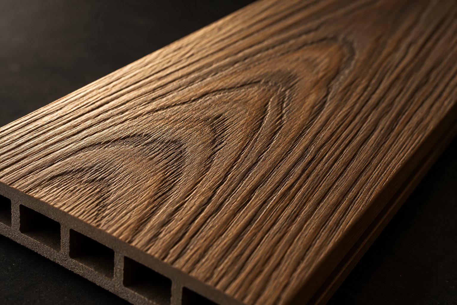
Ever looked at a WPC decking board and mistaken it for real hardwood? That illusion almost certainly came from an embossing station. A WPC decking embossing roller with a wood grain texture pattern is pressed against the profile while it is still warm enough to deform plastically — typically in the temperature range of 60-100 degrees Celsius at the board surface, depending on the polymer matrix. The roller carries a negative image of natural wood grain, knots, and pore structures, and the pressure transfers this pattern into the composite surface as a permanent, mechanically formed texture.
Timing is everything here. The embossing station must be positioned at precisely the right point in the cooling sequence. Too early — when the profile is still too hot and soft — and the roller sinks too deep, distorting the profile cross-section and potentially collapsing thin walls in hollow boards. Too late — when the surface has cooled below its deformation threshold — and the pattern is shallow, inconsistent, or bounces back elastically, leaving a flat, unconvincing impression. Most lines place the embossing unit between the first and second cooling tanks, where surface temperature has dropped enough for structural stability but remains within the workable window for pattern depth.
The embossed texture is mechanically formed, meaning it does not fade or peel over time the way printed or coated finishes can. Deep 3D embossing — where the pattern relief exceeds 0.5 mm — also delivers functional benefits beyond aesthetics. The raised ridges break water surface tension and create micro-drainage channels that improve slip resistance, a measurable safety advantage for pool decks, commercial walkways, and any surface that sees regular moisture.
Brushing and sanding WPC decking profiles take the opposite approach to achieving a natural look. Instead of pressing a pattern into the surface, these stations remove material from it. Wire brushing uses rotating steel or abrasive nylon brushes to strip away the smooth extrusion skin — the glossy, polymer-rich outer layer that forms as the melt contacts the die wall. Removing this skin exposes the wood fiber structure beneath, creating a matte, tactile finish that feels and looks remarkably like sawn timber.
Sanding stations refine this effect further with abrasive belts of controlled grit, producing a uniform surface texture that hides minor extrusion inconsistencies. Both brushing and sanding are typically performed after the profile has cooled to near-ambient temperature, since removing material from a warm, pliable surface would create uneven depth and fuzzy fiber pull-out rather than a clean, controlled texture.
One important trade-off: brushed and sanded surfaces expose wood fibers directly to the environment. Without the protection of the extrusion skin or a cap layer, these fibers are more susceptible to moisture absorption, UV degradation, and staining — which is why brushed-finish boards often require more aggressive stabilizer loading in the formulation or a post-extrusion surface treatment to maintain long-term appearance.
Online Co-Extrusion Surface Treatments
Recall the co-extrusion technology discussed earlier, where a secondary extruder applies a thin polymer shell over the WPC core. That same cap layer serves double duty as both a performance coating and an aesthetic finish — making co-extrusion surface treatment for composite decking one of the most efficient ways to combine protection and visual appeal in a single inline process.
The cap layer accepts pigments and color concentrates far more uniformly than wood-fiber-filled core material. This is because the cap polymer — typically ASA, HDPE, or modified PVC — contains no wood particles to interrupt pigment dispersion. The result is richer, more consistent color across entire production runs, with none of the subtle streaking or mottling that can occur when pigmenting a high-fill WPC compound directly.
Manufacturers have pushed this advantage further with multi-color streaking techniques that deliberately introduce controlled color variation into the cap layer. By feeding two or three slightly different pigment streams into the co-extrusion die simultaneously, producers create boards with realistic wood-tone variation — darker heartwood streaks blending into lighter sapwood tones — that closely mimic the natural color range of species like teak, ipe, or cedar. The key word is controlled: unlike the random fiber-driven color variation in mono-extruded boards, co-extruded streaking is engineered and repeatable from board to board.
Color-matching considerations matter especially for large projects. When a hotel terrace requires 5,000 square meters of decking installed over several months, the buyer expects boards from different production batches to look identical. Co-extrusion makes this feasible because the cap polymer's color is governed by precise pigment dosing rather than variable wood fiber distribution. This batch-to-batch consistency is a significant driver of perceived product value and directly supports premium price positioning in the market.
How do all these finishing methods compare? Here is a summary of when each approach fits best:
- Embossing — Best for creating deep, realistic wood grain textures on standard or co-extruded boards. Enhances slip resistance. Must be performed within the correct temperature window during cooling. Ideal for premium residential and commercial decking where visual realism and safety are priorities.
- Brushing — Best for achieving a natural, sawn-timber look by exposing wood fiber texture beneath the extrusion skin. Performed after full cooling. Suits products targeting customers who prefer a matte, rustic aesthetic. Exposed fibers may require enhanced UV and moisture protection in the formulation.
- Sanding — Best for producing a uniform, refined matte surface that conceals minor extrusion inconsistencies. Often combined with brushing for layered texture effects. Performed after full cooling. Appropriate for mid-range to premium products where tactile quality matters.
- Co-extrusion cap layer — Best for combining surface protection with superior color control and multi-tone wood appearance. Applied inline during extrusion through a secondary extruder and co-extrusion die. Delivers the highest UV resistance, scratch hardness, and stain resistance of any finishing method. Targets premium and ultra-premium market segments where long-term appearance retention justifies higher material and equipment cost.
Many high-end production lines combine methods — applying a co-extruded cap for protection and color, then running the still-warm board through an embossing station to add tactile wood-grain depth on top of the cap layer. This combination delivers both the performance advantages of the polymer shell and the authentic feel of mechanical texturing, a one-two approach that is rapidly becoming the standard for top-tier composite decking products.
Surface finishing shapes what the customer sees and feels. But what happens when the surface — or any other aspect of the board — comes off the line looking wrong? Identifying where a defect originates and knowing which parameter to adjust is the difference between a five-minute correction and a day of wasted production, and that systematic troubleshooting skill is where the next discussion picks up.
Troubleshooting Common WPC Decking Extrusion Defects
A board with a rough surface, a subtle bow, or tiny bubbles just beneath the skin does not announce where it went wrong. It only announces that something, somewhere on the line, drifted out of balance. The challenge for any operator running a WPC decking extrusion line is not just spotting the defect — it is tracing it back to the responsible station and adjusting the right parameter without creating a new problem in the process. This section is designed to serve as a working reference you can return to every time a quality issue appears on the run-out table.
Common WPC Decking Extrusion Defects and Root Causes
WPC decking extrusion defects and solutions fall into a surprisingly small number of categories once you understand the underlying mechanics. Each defect has a visual fingerprint, a traceable cause, and a corrective action that targets the root rather than masking the symptom. The table below covers the seven most frequent issues encountered on production lines processing wood-plastic composite profiles.
| Defect Type | Visual Description | Probable Causes | Corrective Actions |
|---|---|---|---|
| Surface roughness or shark-skinning | Fine, repeating ridges running lengthwise across the board surface, giving a coarse, sandpaper-like texture instead of a smooth finish | Excessive shear stress at the die exit — the melt velocity exceeds the polymer's critical stress threshold. Insufficient external lubricant in the formulation. Die lip temperature too low, increasing surface drag. | Reduce extrusion speed or increase die zone temperature by 5-10 degrees C. Increase external lubricant dosage. Polish the die land surfaces to reduce friction. Confirm that die land length is adequate for the profile geometry. |
| Warping or bowing | Boards curve upward, downward, or sideways after leaving the line — sometimes not visible until hours or days after cutting | Uneven cooling across the profile cross-section, creating asymmetric internal stress. Asymmetric profile wall design without compensating die flow adjustment. Haul-off speed mismatch stretching the profile unevenly. Improper stacking of still-warm boards. | Balance spray nozzle flow or immersion depth so that all surfaces cool at the same rate. Verify calibrator alignment with the die center. Adjust haul-off speed to neutral tension. Stack boards flat on a level surface and allow full cooling before palletizing. |
| Uneven color distribution | Streaks, blotches, or tonal inconsistency across the board width or along its length | Poor pigment dispersion during compounding. Inconsistent feed rate causing variable residence time. Screw wear reducing mixing efficiency. Color concentrate carrier resin incompatible with the WPC matrix. | Extend hot-mixer cycle time or increase mixing intensity for better pigment distribution. Calibrate feeder output. Inspect screw flights for wear — worn flights reduce distributive mixing. Verify color concentrate compatibility with the base resin. |
| Die buildup or die drool | Deposits of degraded material accumulating at the die exit, periodically transferring to the board surface as dark spots, streaks, or raised bumps | Volatile compounds from wood fiber (resins, moisture, organic acids) condensing at the cooler die lip. Inadequate venting in the barrel allowing volatiles to reach the die. Over-temperature in the metering zone accelerating wood fiber decomposition. | Clean die lips on a regular schedule — daily or more frequently with high-wood-content formulations. Verify that barrel vent ports are open and functioning. Reduce metering zone temperature slightly. Ensure wood flour moisture content is below 1% before compounding. |
| Moisture-related foaming or bubbles | Small voids, pinholes, or foam-like texture visible at the surface or within the profile wall when cross-sectioned | Insufficient drying of wood flour before or during the hot-cold mixing stage. Blocked or undersized extruder vent ports allowing steam pressure to build. Ambient humidity absorbed by hygroscopic compound during storage between compounding and extrusion. | Verify wood flour moisture is under 1% after the hot-cold mixer cycle. Clean and inspect all barrel venting zones — ensure vacuum venting is operational and pulling the correct negative pressure. Store compounded material in sealed containers or climate-controlled rooms. Consider adding a desiccant hopper dryer above the extruder feed throat. |
| Inconsistent wall thickness | Measurable variation in wall thickness across the board width or between hollow-profile chambers — detected by caliper checks or cross-section cuts | Worn screw flights reducing conveyance consistency and creating pulsating melt delivery. Die flow channel imbalance — one side of the die receives more material than the other. Calibrator misalignment forcing the profile off-center. Haul-off grip uneven across the board width. | Measure screw flight diameter and compare to original specification — worn screws reduce mixing efficiency and create inconsistent melt flow. Re-balance die flow channels using adjustable choke bars or restrictor bolts. Realign calibrator to die centerline. Inspect haul-off pads or belts for uneven wear. |
| Poor surface finish after embossing | Shallow, incomplete, or inconsistent wood-grain pattern — embossing appears crisp in some areas and faded or absent in others | Profile surface temperature too low at the embossing station, meaning the material is too rigid to accept the pattern fully. Uneven surface temperature across the board width. Embossing roller pressure insufficient or unevenly distributed. Roller pattern worn or contaminated with compound residue. | Reposition the embossing station closer to the die exit, or reduce upstream cooling intensity to raise surface temperature at the embossing point. Verify roller pressure is uniform with a pressure-indicating film or feeler gauges. Clean and inspect the embossing roller surface. Replace worn rollers that no longer produce adequate pattern depth. |
You will notice that several defects share overlapping root causes. The shark skin surface defect in wood plastic composite production, for example, responds to both die temperature and lubricant adjustments — two parameters that also affect die drool behavior. Similarly, WPC extrusion warping and bowing troubleshooting often leads back to cooling system issues that can simultaneously contribute to inconsistent wall thickness. This overlap is not a coincidence. It reflects the interconnected nature of extrusion, where a single upstream deviation cascades through multiple downstream quality indicators.
Systematic Troubleshooting Approach
When a defect appears, the instinct is to start adjusting the nearest dial. Resist it. Experienced operators follow a structured methodology that prevents the common trap of chasing one problem into three new ones.
The approach works in four steps:
- Identify the defect visually and classify it. Use the table above or a similar reference to name what you are seeing. A rough surface and a foamed surface may look similar at a glance, but they originate from completely different causes — shear stress versus moisture. Misclassification at this stage sends you down the wrong diagnostic path.
- Trace the defect to the responsible station. Ask where in the line the defect could have been created. Surface roughness and shark-skinning point to the die and the last barrel zone. Warping points to cooling and haul-off. Foaming and bubbles in a moisture foaming bubbles WPC extrusion line scenario point all the way back to raw material preparation or barrel venting. Dimensional drift points to the extruder-haul-off speed relationship or calibrator condition. Every defect has a home station — find it before touching anything.
- Adjust one variable at a time. This discipline is what separates effective troubleshooting from expensive guesswork. If you suspect die temperature is causing surface roughness, raise it by 5 degrees C — and change nothing else. Resolving extrusion defects requires a methodical approach that isolates each variable so you can clearly see whether the adjustment helped, had no effect, or made things worse.
- Allow the line to stabilize before evaluating. A WPC extrusion line does not respond instantly to parameter changes. Thermal mass in the barrel, die, and calibrator means that a temperature adjustment can take 10-20 minutes to fully propagate through the melt stream. Changing a second variable before the first one has taken effect makes it impossible to know which change produced the result you observe. Patience here saves hours of circular adjustments later.
Most WPC extrusion defects originate from one of two root causes: residual moisture in the feed material, or a parameter imbalance between screw speed and haul-off speed. When a new defect appears, check these two factors first — they account for the majority of quality deviations on a running line.
That principle deserves emphasis because it simplifies an otherwise overwhelming diagnostic landscape. Moisture in the compound causes foaming, bubbles, die drool (from volatiles), surface pitting, and even color shifts as steam disrupts pigment distribution. Screw speed-haul-off imbalance causes dimensional variation, warping, internal stress, and surface distortion at the embossing station. Confirm both of these are in balance before investigating more exotic causes — you will solve the majority of issues before they demand deeper analysis.
One final practical note: keep a logbook. Record every defect, the parameter state when it appeared, what adjustment resolved it, and how long stabilization took. Over weeks and months, this log becomes the most valuable troubleshooting document on the factory floor — a custom reference calibrated to your specific line, your formulation, and your operating conditions. No generic guide, including this one, can replace that accumulated operational intelligence.
Solving defects as they arise keeps production moving, but the broader goal is building a line operation that prevents them systematically. That means planning for the right factory layout, meeting recognized quality standards, and choosing equipment and component partners who understand the specific demands of WPC processing — decisions best addressed before the first kilogram of compound ever reaches the hopper.
Planning Your Line Layout and Meeting Quality Standards
Troubleshooting keeps boards flowing off an existing line, but the decisions that shape long-term production success happen months earlier — when you are sketching factory floor plans, sizing electrical panels, and vetting potential equipment partners. WPC decking extrusion line layout planning is where operational ambition meets physical and financial reality. Get this stage right, and every chapter of this guide works in your favor. Get it wrong, and you spend years compensating for constraints that were avoidable from the start.
Production Line Layout and Utility Requirements
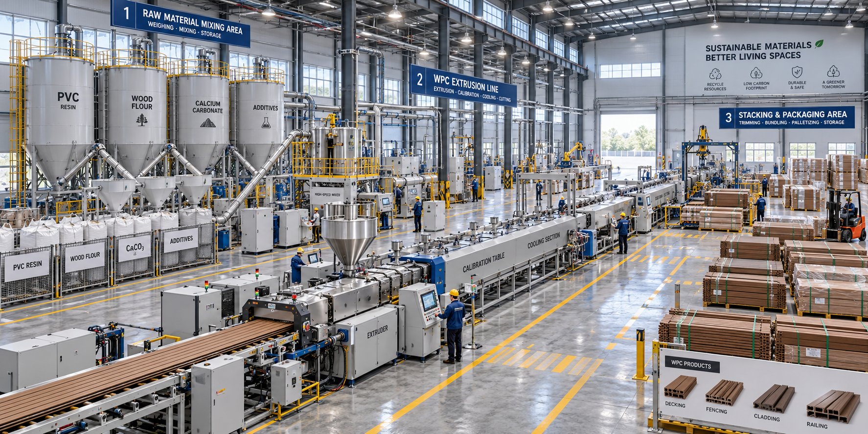
A complete WPC decking production facility is not just an extruder sitting in a warehouse. It is three distinct zones that must be arranged for efficient material flow, safety, and scalability.
Zone 1 — Mixing and compounding room. This is where raw materials arrive, get stored, weighed, and processed through the hot-cold mixer system (and pelletizer, if your formulation requires one). Floor space here needs to accommodate bulk storage silos or bag stations for wood flour, polymer resin, and additives, plus the mixer footprint itself and clearance for forklift access. Climate control matters — wood flour absorbs moisture rapidly, so raw material storage should be enclosed, dry, and separated from the main production hall. Industrial-grade dust extraction and filtration are non-negotiable; fine wood flour creates both respiratory hazards and explosion risks in enclosed spaces.
Zone 2 — Extrusion hall. This is the heart of your WPC extrusion line utility requirements setup. A single extrusion line typically spans 20 to 30 meters in length, but you should allocate at least 35 meters of straight-line distance per line to accommodate the extruder, calibration tables, cooling tanks, haul-off, cutting station, and run-out table — plus room for operators to move around the equipment safely. Ceiling height needs to clear any overhead cranes used for screw and barrel removal during maintenance. If you plan to run multiple lines in parallel, add lateral clearance between them for die changes and downstream equipment service access.
Zone 3 — Stacking, inspection, and packaging area. Cut boards exit the line and need space for automated or manual stacking, quality inspection stations, and palletizing before warehouse storage or direct shipping. This zone is frequently undersized in initial layouts, creating bottlenecks when production output exceeds the stacking system's capacity.
Utility requirements for the complete facility deserve careful upfront engineering:
- Electrical supply — A standard WPC extrusion line easily exceeds 200 kW of connected load per line, driven by extruder drive motors, barrel heater bands, haul-off drives, and cooling system pumps. Your facility's transformers and internal distribution must handle this continuous industrial draw with headroom for startup surge currents.
- Cooling water circulation — Calibration tables and cooling tanks depend on a steady supply of temperature-controlled water. Industrial chillers, high-volume circulation pumps, and filtration systems form a closed loop that must maintain strict temperature gradients — typically delivering water at 15-25 degrees Celsius depending on the profile type and polymer matrix.
- Compressed air — Pneumatic actuators operate cutter clamping, calibrator adjustments, and various material handling functions throughout the line. A dedicated compressor with a dryer and receiver tank, sized for the combined air demand of all stations, prevents pressure drops that disrupt automated sequences.
Upstream-downstream integration ties these zones into a continuous production flow. The mixing room's output — whether pelletized granules or dry-blended powder — feeds the extrusion hall via pneumatic conveying or gravity hoppers positioned above the extruder feed throat. At the output end, automated stacking systems receive cut boards directly from the run-out table, minimizing manual handling and reducing the labor needed to keep pace with a line producing hundreds of linear meters per hour.
Quality Standards and Testing for WPC Decking Output
Imagine shipping 10,000 boards to a hospitality project, only to face a rejection because no one verified that the decking met the structural performance standard specified in the contract. Quality standards for WPC decking are not abstract certifications hung on a wall — they are the technical framework that determines whether your product can legally and contractually be installed on a project.
Two international standards dominate the WPC decking space:
- ASTM D7032 — This U.S.-based standard establishes performance ratings for WPC and plastic-lumber deck boards, stair treads, guards, and handrails in exterior applications. It covers flexural performance, temperature and moisture effects, UV resistance, freeze-thaw durability, biodeterioration, fire performance, creep-recovery, and slip resistance. Meeting ASTM D7032 WPC decking quality standards is essential for any product entering the North American market.
- EN 15534-4 — The European counterpart, which specifies characteristics for exterior WPC decking profiles and tiles made from cellulose-based materials and thermoplastics. Importantly, this standard covers the board itself but does not validate a complete deck system — support rails, hardware, and fastening packages require separate verification.
Applicable ISO standards — such as ISO 178 for flexural properties and ISO 4892 for UV weathering test methods — often serve as the underlying test procedures referenced within both ASTM and EN frameworks.
The key tests your production must consistently pass include:
| Test Category | What It Measures | Extrusion Line Connection |
|---|---|---|
| Dimensional tolerance | Width, height, wall thickness, and straightness against specified limits | Controlled by die geometry, calibrator alignment, haul-off speed, and cooling uniformity |
| Flexural strength and modulus | Load-bearing capacity and stiffness under bending | Determined by formulation (fiber-polymer ratio, coupling agent effectiveness) and consistent compounding |
| Moisture absorption | Weight gain after prolonged water immersion | Influenced by wood fiber encapsulation quality during compounding and surface porosity from extrusion conditions |
| UV weathering resistance | Color change, surface chalking, and mechanical property retention after accelerated UV exposure | Depends on UV stabilizer loading in the formulation and, for co-extruded boards, cap layer integrity |
| Slip resistance | Coefficient of friction under wet and dry conditions | Directly affected by surface finishing method — embossing depth, brushing texture, or cap layer surface profile |
The connection is clear: every row in that table traces back to a specific extrusion line function or process control point. Consistent test results are not achieved by testing alone — they are achieved by maintaining the process parameters, maintenance schedules, and material preparation standards discussed throughout this guide. Testing simply confirms that your line is doing what it should.
Evaluating Equipment Suppliers and Component Partners
How do you choose a WPC decking extrusion equipment supplier when dozens of manufacturers offer what appear to be similar lines? Price is the most visible differentiator, but it is also the least reliable. The real evaluation criteria go deeper — into technical transparency, service infrastructure, and the quality of every component inside the machine.
Use this framework when shortlisting potential line manufacturers and component suppliers:
- Technical specification transparency — Demand itemized lists of all major components: motor brands, gearbox specifications, PLC control system manufacturer, barrel and screw metallurgy, and die steel grade. Generic proposals hide cheap components. If a supplier cannot or will not detail what is inside the machine, treat that as a disqualification signal.
- Factory Acceptance Testing (FAT) — Before the line ships, you should be able to visit the manufacturer's facility, provide your exact raw material formulation, and watch the line run at full capacity using your recipe. If the machine cannot produce quality boards during the FAT, do not authorize the shipment. This single step eliminates more commissioning headaches than any other contractual clause.
- Installation and training support — Prioritize suppliers offering turnkey installation rather than equipment-only delivery. Turnkey agreements mean the vendor's engineers assemble, wire, calibrate, and commission the line on your floor — and train your operators on formulation-to-machine tuning specific to your product range.
- Spare parts availability and lead times — A line sitting idle waiting for an overseas heater band or thermocouple destroys profitability. Clarify whether the supplier maintains regional spare parts inventories and what lead times look like for critical wear components like screws, barrels, and dies.
- Certifications and safety compliance — Verify legitimate CE or equivalent certifications, adherence to electrical safety standards, and interconnected emergency stop protocols across all stations. Quality certifications such as ISO 9001 provide baseline assurance of the supplier's manufacturing consistency.
- Financial stability and reference customers — A financially stable supplier is less likely to face operational disruptions. Request references from existing WPC producers running the same line configuration and ask direct questions about uptime, service responsiveness, and long-term component durability.
- Specialized component partners for critical wear items — A reliable WPC extrusion line depends not only on the machine OEM but also on the quality of the components inside it — especially the screws and barrels that endure constant abrasive wear. Working with specialist component suppliers ensures access to application-specific metallurgy, faster replacement turnaround, and engineering support tailored to WPC processing demands. For example, NANHAIYA specializes in conical twin screw barrels for PVC and WPC extrusion, offering custom-engineered barrels with bimetallic linings and precise taper geometry matched to specific extruder models. Having a relationship with a dedicated partner like this — before a barrel reaches end of life — means you can source a precision replacement without the extended lead times that OEM channels sometimes require, keeping your line at peak plasticizing performance.
The broader principle behind all of these criteria is straightforward: evaluate the entire supply ecosystem, not just the nameplate on the extruder. The mixing system, the die steel, the calibrator precision, the screw metallurgy, the control system architecture, and the after-sales support network all contribute equally to whether your line produces consistent, standards-compliant WPC decking boards year after year — or becomes an expensive source of frustration.
Every section of this guide has traced a single thread: in a WPC decking extrusion line, everything connects. Formulation choices drive screw design. Screw geometry shapes melt quality. Melt quality determines what the die, calibrator, and cooling system must deliver. Surface finishing translates engineering into market value. Maintenance preserves it all. And the planning decisions you make before any of that begins — layout, utilities, standards, and supplier partnerships — set the ceiling on what the entire operation can achieve. Build that foundation with the same precision you expect from the boards coming off the end of the line, and the rest follows.
Frequently Asked Questions About WPC Decking Extrusion Lines
1. What are the main components of a WPC decking extrusion line?
A complete WPC decking extrusion line includes a hot-cold mixer system for raw material preparation, a twin screw extruder (conical for PVC-based WPC or parallel for PE/PP-based WPC), a profile die, a vacuum calibration table, spray or immersion cooling tanks, a caterpillar-type haul-off unit, a flying saw or guillotine cutter, and a stacking table. Co-extrusion setups add a secondary extruder and a multi-channel die for applying a protective cap layer. Supporting utilities include cooling water chillers, compressed air systems, and dust extraction. Each station must be precisely coordinated — the die shapes the melt, the calibrator locks dimensions under vacuum, and the haul-off speed must match the extruder output to maintain consistent wall thickness across every board.
2. What is the difference between mono-extrusion and co-extrusion for WPC decking?
Mono-extrusion uses a single extruder to produce a board where the core and surface share the same WPC material. It costs less to set up and operate but offers limited UV, scratch, and stain resistance because wood fibers are exposed at the surface. Co-extrusion adds a secondary extruder that applies a thin polymer cap layer — typically ASA, HDPE, or modified PVC — over the WPC substrate during the extrusion process. This cap delivers dramatically better color retention, scratch hardness exceeding Shore D 65, and superior stain resistance. Co-extrusion lines cost roughly 30-50% more in capital investment but unlock premium market segments with higher margins and longer product warranties.
3. How do you troubleshoot common defects on a WPC decking extrusion line?
Effective troubleshooting follows a four-step method: visually identify and classify the defect, trace it back to the responsible station, adjust one parameter at a time, and allow 10-20 minutes for the line to stabilize before evaluating results. The most frequent WPC extrusion defects include surface roughness caused by excessive die shear stress, warping from uneven cooling, foaming from residual moisture in wood flour, and inconsistent wall thickness from worn screw flights. A practical starting point is checking two factors first — wood flour moisture content (which should be below 1%) and the balance between screw speed and haul-off speed — since these account for the majority of quality issues on running lines.
4. Why do screws and barrels wear faster in WPC extrusion compared to standard plastic extrusion?
Wood flour naturally contains silica particles that act as fine abrasives against metal surfaces during processing. When combined with mineral fillers like calcium carbonate or talc commonly used in WPC formulations, the abrasive load intensifies significantly. This constant erosion widens the clearance between screw flight tips and the barrel bore, reducing plasticizing efficiency, destabilizing melt pressure, and degrading output quality over time. Formulations with higher wood fiber content — 55-60% — accelerate wear dramatically. Solutions include bimetallic barrel linings with hardness values of HRC 58-65, deep gas nitriding on screw surfaces, and tungsten carbide hard-facing on flight tips. Specialists like NANHAIYA provide custom-engineered conical twin screw barrels with application-specific metallurgy for PVC and WPC extrusion lines, helping producers restore plasticizing performance faster than OEM replacement channels typically allow.
5. Should I use pelletized feedstock or direct dry-blend feeding for my WPC extrusion line?
The choice depends primarily on your polymer matrix. PE and PP-based WPC formulations benefit significantly from pelletizing because these polyolefins require full melt blending to achieve proper wood fiber encapsulation and complete coupling agent reaction. Pelletized feedstock delivers highly consistent melt quality and stable throughput, though it requires a separate compounding extruder that adds capital cost. PVC-based WPC works well with direct dry-blend feeding because PVC undergoes a unique gelation behavior on twin-screw extruders, allowing effective compounding from dry blend in a single pass. Direct feeding saves capital investment and reduces thermal exposure on wood fibers to one heat cycle instead of two, but demands a well-designed hot-cold mixer system and careful screw configuration to maintain feed consistency.
Written by
Nanhaiya Technical Team
Zhoushan Nanhaiya Plastic Machinery Co., Ltd.
The Nanhaiya technical team supports screw and barrel manufacturing projects through application review, technical communication, custom manufacturing coordination, and production and quality control.
Discuss Your Application
Related Articles
More insights on screw barrel technology and plastics processing.
Blown Film Problems Decoded: What Your Bubble Is Telling You
Oct 23, 2026
Solve blown film problems from resin to roll. Learn to identify gels, gauge variation, bubble instability, die defects, and downstream failures with actionable fixes.
Read Article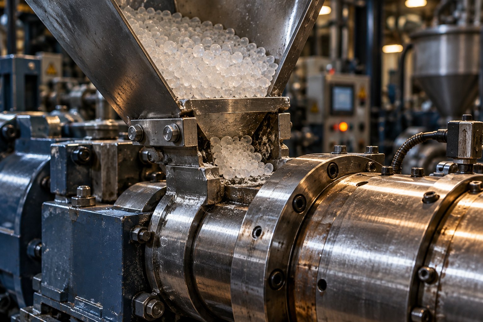
Your Extruder Feeding Instability Isn't Random — Here's Why
Oct 22, 2026
Extruder feeding instability causes surging output and scrap. Learn the 6 root causes, polymer-specific fixes, wear diagnostics, and preventive protocols.
Read Article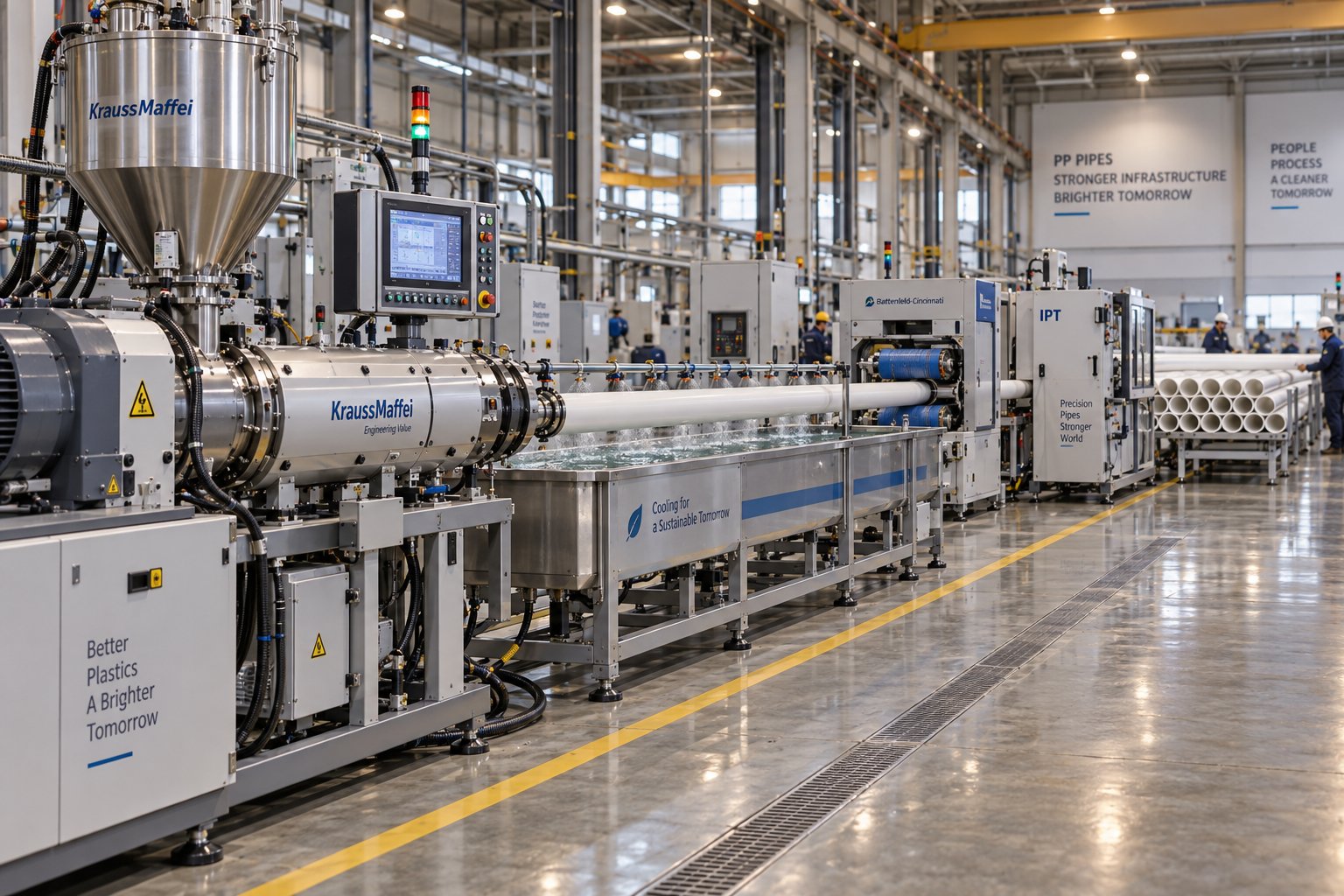
Your PP Pipe Extrusion Machine Is Only As Good As Your PP Grade
Oct 22, 2026
Learn how PP pipe extrusion machines differ from generic lines. Covers PP grade selection, key components, process steps, specs, maintenance, and buying tips.
Read ArticleLooking for something else?
Search by material, symptom or product and jump straight to the relevant page.
These are navigation suggestions based on keyword matching — not a quotation, not a delivery commitment, and not a substitute for engineering review. Final specification is confirmed by our engineers against your drawings and processed material.
Need help with screw barrel selection?
Share your machine model, processed material and application. Our team can help with pricing and technical support.