

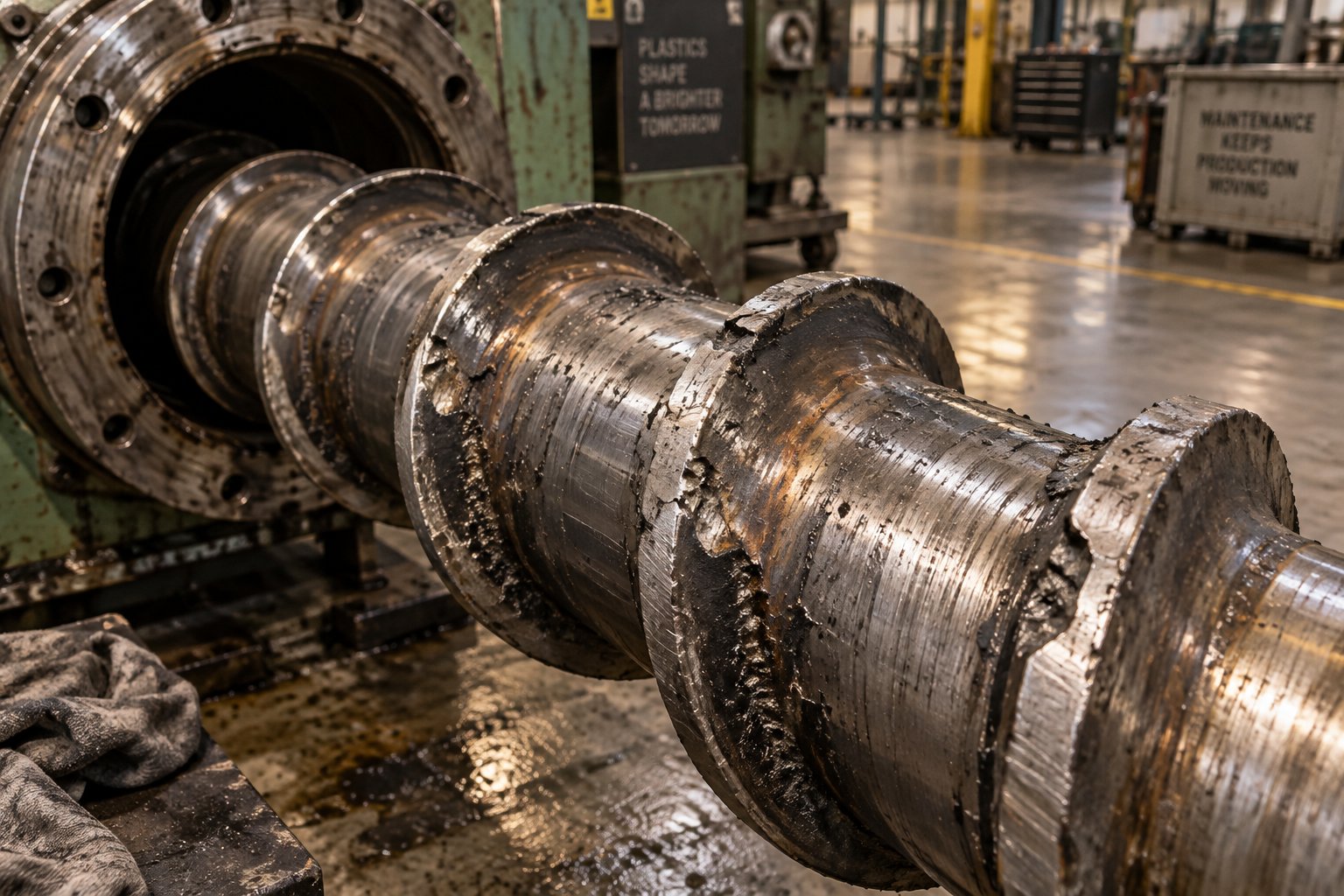
Recognizing Screw Barrel Wear Symptoms Before Production Suffers
It rarely starts with a maintenance report. Instead, an operator on the production floor notices the output doesn't look right — maybe the extrudate surface has gone rough, or shot weights are drifting on the injection molding press. Reject bins fill a little faster. The motor draws more amps than it did last month at the same RPM. Something feels off long before anyone pulls the screw and barrel for inspection.
Screw barrel wear symptoms are the collection of operational, visual, and measurable indicators that tell you clearances between the screw and barrel have exceeded acceptable tolerances. These signs range from subtle — a slow decline in throughput per revolution — to obvious, like unmelted pellets showing up in finished parts. Catching them early is the difference between a planned repair during scheduled downtime and a catastrophic seizure that shuts a line down for days and costs tens of thousands of dollars in lost production, emergency parts, and wasted material.
Why Wear Symptoms Matter More Than Scheduled Maintenance Intervals
You might assume a calendar-based maintenance schedule keeps you safe. Replace the extrusion screw every 18 months, inspect the barrel annually, and move on. The problem? Wear progression is non-linear. A screw and barrel processing unfilled polyethylene may run for years with minimal clearance change, while the same components running glass-filled nylon could reach critical wear thresholds in a fraction of that time. Throughput volume, operating temperatures, and even moisture content in the resin all accelerate or slow the rate of degradation. Symptom-based monitoring — watching what the machine is telling you in real time — consistently outperforms rigid schedules because it responds to actual conditions, not assumptions.
How This Diagnostic Guide Is Organized
This guide follows the same path a real-world diagnosis takes: it starts with the production-floor red flags operators spot first, then moves into component-specific symptoms that separate screw wear from barrel wear, zone-level diagnosis across the feed, transition, and metering sections, quantitative measurement confirmation, differential diagnosis to rule out look-alike problems, and finally, remediation options. Whether you're running extruder screws and barrels on a continuous line or managing a fleet of injection molding presses, this structure gives you a systematic path from "something seems wrong" to a confirmed, data-backed decision.
Most operators detect wear through production anomalies long before maintenance teams measure clearances — making symptom literacy a front-line skill that saves both time and money.
The subtle shifts happening on your production floor right now may already be pointing to clearance problems. The question is whether you're reading those signals — or waiting until the machine makes the decision for you.
Production Floor Red Flags That Signal Worn Screws and Barrels
Imagine you're running the same recipe, the same resin lot, and the same process settings you've used for months — yet the numbers on the HMI panel don't match what they used to. Output is down. Melt temperature is up. Reject rates are creeping higher. Nothing has changed on paper, but the machine is behaving differently. These are the operational symptoms that process technicians and operators encounter first, often weeks or months before anyone opens the barrel for inspection. Recognizing them early is what separates a planned maintenance event from an expensive emergency.
Output and Throughput Decline at Constant RPM
A gradual drop in output rate at the same screw speed is the single most reliable early indicator of wear-induced leakage flow. The concept behind it is straightforward: as clearance between the screw flights and the barrel bore increases, more molten polymer leaks backward over the flights instead of being pushed forward. The screw works just as hard, but delivers less material per revolution.
The key metric to track here is specific rate — output (in lb/hr or kg/hr) divided by screw speed (RPM). When extruder screws and barrels are in good condition, this ratio stays remarkably consistent for a given resin and set of process conditions. A healthy approach is to log specific rate during stable production runs and establish a baseline for each product. Extrusion experts at Plastics Technology identify reduction in specific rate as one of the main signs of wear, noting that operators initially compensate by simply increasing screw speed to maintain throughput — which works for a while but masks the underlying problem.
When should the trend concern you? There is no universal percentage cutoff that applies to every machine and resin combination, but a sustained decline of 5-15% from your established baseline is a strong signal that clearances deserve attention. For a barrel extruder processing critical-duty products like medical tubing, even smaller deviations warrant investigation. For less demanding applications, you may tolerate more drift — but the trend line itself is what matters. A flat or stable specific rate means healthy components. A consistently declining curve means wear is progressing.
Melt Quality Degradation and Visual Defects
While specific rate is the most quantifiable early warning, the defects you can actually see and touch often trigger the first round of questions. Worn clearances degrade melt quality in several overlapping ways, and the resulting defects show up on the extrudate or molded part:
- Unmelted particles or gels: Increased clearance reduces the screw's ability to generate the shearing action needed to fully melt all pellets, especially at higher throughput rates. You'll find hard spots, unmelted specks, or gel-like inclusions in the finished product.
- Streaking and color inconsistency: When the screw can no longer seal tightly against the barrel wall, mixing efficiency drops. Color concentrates or additives don't disperse evenly, producing visible streaks or shade variation across the product.
- Surface roughness on extrudate: A rough, shark-skin-like surface or dull finish on profiles, film, or sheet can indicate poor melt homogeneity from worn extruder screws that are no longer delivering a uniform melt stream to the die.
These visual screw barrel wear indicators tend to worsen gradually, which makes them easy to normalize. An operator who sees the same part every day may not notice a slow drift in surface quality — but comparing current samples against a retained standard from when the screw and barrel were new can reveal surprising differences.
Rising Melt Temperature and Energy Consumption
Here's a detail that catches many operators off guard: worn clearances actually cause the melt temperature to rise, even when barrel zone setpoints haven't changed. The reason is two-fold. First, back-leakage over worn flight tips generates additional shear heating as polymer is forced through the enlarged gap. Second, the increased film thickness between the screw flight and barrel wall reduces the heat-transfer coefficient at the barrel surface, making it harder for barrel cooling to remove excess heat. Research from Dow and TWWomer & Associates demonstrated this clearly — a 100-mm screw running PE at constant rate saw discharge temperatures climb as flight clearance increased, eventually reaching levels that made downstream operations like blown film unstable.
The practical consequences cascade quickly. To compensate for the elevated melt temperature, operators lower the screw speed or adjust barrel temperatures downward, which reduces throughput and extends cycle times. Motor amperage at a given RPM may also increase as the screw fights to maintain pressure against greater internal leakage. The result is higher energy consumption per unit of output — an extruder output decline cause that shows up on utility bills long before anyone suspects hardware wear.
Taken together, these red flags form a checklist every operator and process technician should keep in mind. If you're observing more than one of these simultaneously, the probability of meaningful screw or barrel wear increases significantly:
- Declining specific output rate (kg/hr per RPM) against your baseline
- Increased reject rate or quality complaints from downstream
- Rising discharge melt temperature at constant process settings
- Surging or pulsating flow visible at the die or in product dimensions
- Longer cycle times or reduced line speeds needed to maintain quality
- Increased energy consumption (kWh) per unit of finished product
Any single item on this list could have alternative explanations — a bad heater band, an inconsistent resin lot, or a clogged screen pack. That overlap is exactly why the next critical step is determining whether the symptoms point to the screw, the barrel, or both.
Separating Screw Wear Symptoms from Barrel Wear Symptoms
That checklist of production-floor red flags tells you something is worn — but it doesn't tell you what is worn. And that distinction matters enormously, because the fix for a worn screw and the fix for a worn extruder barrel are completely different paths. One leads to re-screwing or flight rebuilding. The other leads to barrel re-lining or full replacement. Misidentifying the source means spending thousands of dollars and days of downtime solving the wrong problem. Here's how to read the clues that each component leaves behind.
Symptoms That Point to Screw Wear
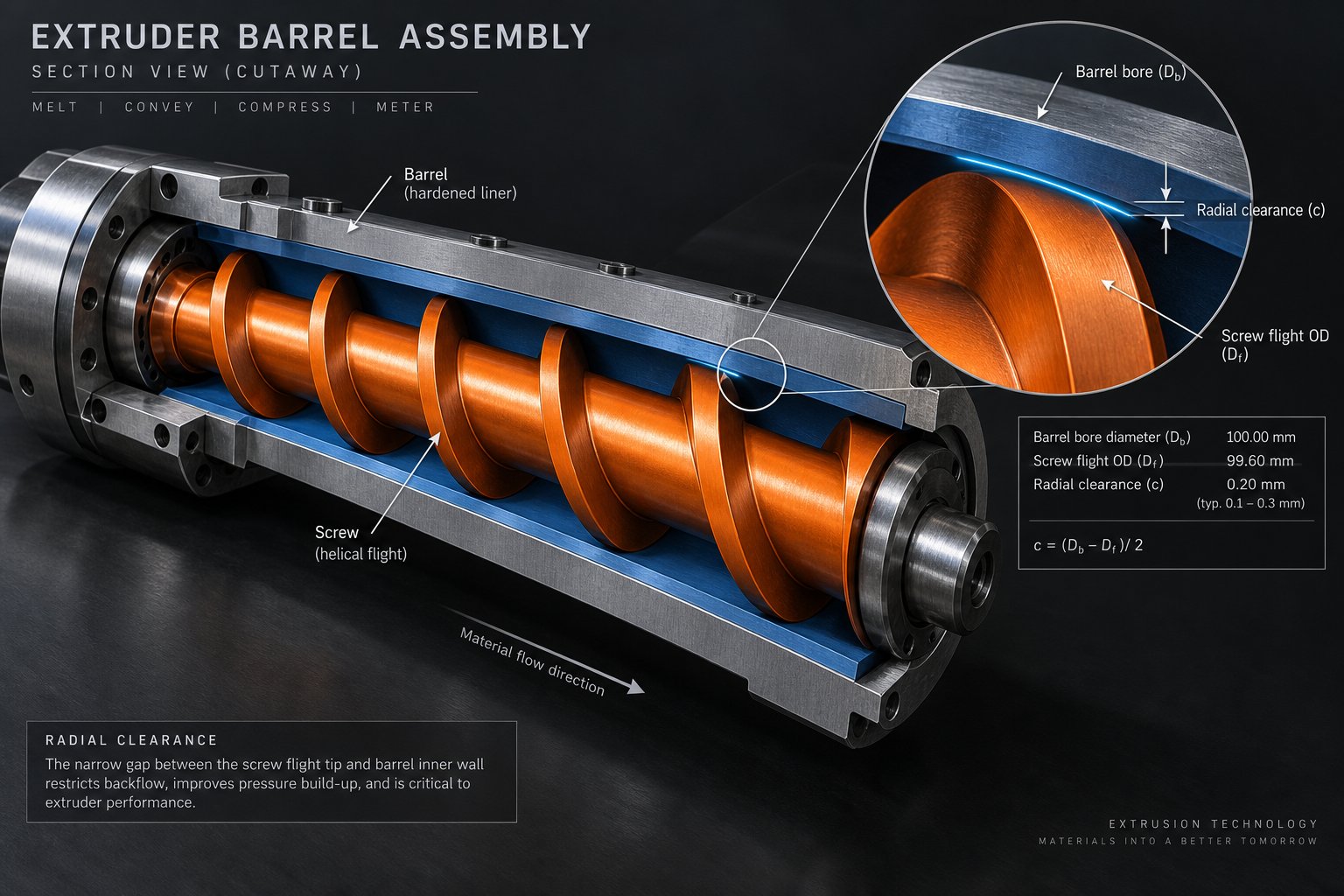
Screw wear overwhelmingly shows up as a reduction in the outer diameter (OD) of the screw flights — the raised ridges that seal against the barrel wall and push material forward. As the flight tips lose material, the radial clearance between screw and barrel widens, and the screw's ability to generate a tight seal disappears. Screw flight wear symptoms follow a recognizable pattern when you pull the component for inspection:
- Flight OD reduction: The most common form. Hard-facing material on the flight tips wears away, reducing the outside diameter. Industry guidelines note that flight hard facing is typically about 0.060 inches thick, and once it's gone, the softer base metal erodes rapidly.
- Flight land erosion: The flat top surface of the flight becomes narrow, sharp, or ragged instead of maintaining its original width. This reduces the sealing area and accelerates further wear.
- Root diameter reduction: In the metering zone especially, erosion of the screw root reduces the channel depth and the screw's pressure-generating capacity.
- Surface scoring or galling: Scratches, grooves, or rough patches on the flight flanks indicate metal-to-metal contact or abrasive particle damage.
The operational signature of screw wear is straightforward: output loss is the dominant symptom. The screw simply cannot seal against the barrel wall well enough to push material forward efficiently. You'll notice declining specific rate first, followed by the melt quality issues described in the previous section. Because the screw rotates continuously against the stationary barrel, wear on the flight tips tends to be relatively uniform along the screw length — though certain zones wear faster depending on the resin being processed.
Symptoms That Point to Barrel Wear
While screws wear on their outer surfaces, extruder barrels wear on their inner bore. The symptom profile has a different character — and catching it early requires different inspection techniques.
- Barrel bore enlargement: The internal diameter of the barrel increases beyond its original specification. This is measured with bore gauges at multiple points along the barrel length, and even a few thousandths of an inch of enlargement significantly increases leakage flow. The result is back-flow that robs the screw of pumping efficiency, much like screw wear — but the root cause is the housing, not the rotating component.
- Bimetallic liner wear-through: Most extruder barrels use a wear-resistant bimetallic liner on the bore surface. When this liner — typically around 0.060 inches thick — wears through, it exposes the softer base steel underneath. Once that happens, bore enlargement accelerates dramatically because the base metal offers far less resistance to abrasion and corrosion.
- Localized bell-mouthing: Rather than wearing uniformly, barrels often develop enlarged zones — particularly at the feed throat opening and in the transition zone where partially melted abrasive solids exert the highest forces. This localized bore enlargement creates pockets of excessive clearance that can cause surging and pressure instability even when the rest of the barrel is within specification.
The operational signature of barrel wear tends to be more localized than screw wear. You might see surging that corresponds to a specific barrel zone, or temperature control anomalies isolated to one section. Because an iron-based bimetallic-lined barrel typically lasts about three times the service life of a screw, barrel wear is less frequent — but when it occurs, it's usually more expensive to remediate.
When Both Components Wear Simultaneously
Here's where things get tricky. In real-world production, screws and barrels rarely wear in isolation. The screw flight OD shrinks while the barrel bore grows — and the combined effect on clearance is not simply additive. It's exponential in its impact on leakage flow.
Think of it this way: if the original radial clearance was 0.004 inches per side and the screw wears 0.003 inches while the barrel bore enlarges by 0.003 inches, the total clearance has jumped to 0.010 inches per side — roughly 2.5 times the original. Leakage flow through that gap increases as a function of the clearance cubed, meaning that a doubling of clearance can produce an eightfold increase in back-leakage. The performance decline that might have been manageable with either component worn alone becomes severe and sudden when both are degraded.
This is why experienced maintenance teams always measure both the screw OD and the barrel bore ID whenever one component is pulled for inspection. Replacing only the screw while leaving a worn barrel in service — or vice versa — delivers disappointing results because the remaining worn component still contributes excessive clearance.
To help you perform an initial assessment before pulling the screw, the following table maps common symptoms to their most likely source:
| Symptom | Likely Screw Wear | Likely Barrel Wear | Both |
|---|---|---|---|
| Gradual, uniform output decline | ✔ | ✔ | |
| Surging localized to one barrel zone | ✔ | ✔ | |
| Unmelted particles or gels in product | ✔ | ✔ | |
| Rising discharge melt temperature | ✔ | ✔ | ✔ |
| Visible scoring or roughness on screw flights | ✔ | ||
| Accelerated wear after recent screw replacement | ✔ | ||
| Sudden severe output loss (not gradual) | ✔ | ||
| Temperature runaway in a specific zone (heater at 0%, cooling at 100%) | ✔ | ✔ | |
| Torque or motor current drop at constant RPM | ✔ | ✔ | |
| Bore measurement shows localized bell-mouthing | ✔ |
One symptom in the table deserves special attention: if you've recently installed a new screw and performance is still poor, that's a strong indicator the barrel bore has enlarged beyond tolerance. The new screw's correct OD dimensions can't compensate for an oversized bore — and the mismatch confirms the barrel itself needs measurement and likely remediation.
Knowing whether you're dealing with screw wear, barrel wear, or both points you toward the right fix. But the location of that wear along the screw's length reveals even more — specifically, what's causing the damage and which processing conditions are driving it.
Wear Symptoms by Screw Zone from Feed to Metering
A plastic extruder screw isn't a uniform piece of steel doing the same job from end to end. It's three machines in one — a solids conveyor, a compression melter, and a pressurized pump — each occupying a distinct zone with its own geometry, pressures, and failure modes. Wear doesn't spread evenly across those zones. It concentrates wherever the combination of pressure, abrasion, and thermal stress is most aggressive. Understanding which zone is wearing — and what that wear looks like — tells you not just how bad the problem is, but why it's happening and what resin or process condition is driving it.
Feed Zone Wear Symptoms
The feed zone is where solid pellets enter the barrel and begin their journey forward. Here, the screw flights act more like a conveyor than a pump — gripping unmelted pellets against the barrel wall and pushing them toward the compression section. Wear in this zone doesn't usually produce the dramatic output losses you'd see from metering zone degradation, but it creates a different set of headaches that are easy to misdiagnose.
The most common sign of feed zone screw wear is inconsistent solids conveying. You'll notice throughput fluctuations, particularly at startup or during transitions between materials. The machine takes longer to stabilize after a speed change, or output varies cyclically even under steady-state conditions. In some cases, you can actually hear the difference — a change in the sound from the feed throat area as pellets slip against worn flights instead of being gripped and driven forward.
Why does this happen? Worn feed zone flights lose the sharp edges and full OD diameter they need to "bite" into the solid bed of pellets. As the flight tips round off or lose height, pellets rotate with the screw instead of being conveyed forward. The result is reduced solids-conveying efficiency — the machine's intake valve, essentially, starts leaking.
On the barrel side, feed zone wear often appears as bell-mouthing at the feed opening — a localized enlargement of the barrel bore right where pellets drop in from the hopper. This is driven by the abrasive impact of hard, cold pellets hitting the barrel wall at high velocity. Feed throat cooling issues can accelerate this pattern, because inadequate cooling allows pellets to begin softening prematurely, creating a sticky layer that increases friction and wear at the entry point. Processing recycled materials with metal contaminants or irregular particle shapes makes this even worse.
Transition and Compression Zone Wear Symptoms
If there's a single zone that earns the title of "wear hotspot," it's the transition section. This is where the screw channel depth decreases, compressing the material from a loose bed of pellets into a dense, partially melted mass. The physics are brutal: high pressure, partially melted abrasive solids grinding against metal surfaces, and mechanical forces that push the screw off-center under asymmetric pressure loads.
Analysis of thousands of rebuilt screws confirms that the transition section and the last few turns of metering consistently show the most severe OD wear. The combination of the highest pressures and temperatures in these areas drives increased friction, making wear rates significantly higher than in the feed zone.
The symptoms you'll observe from transition zone degradation are directly tied to melt quality:
- Unmelted particles and gels: The compression zone is responsible for converting solid pellets into a homogeneous melt. When flight tips wear down and clearance increases, the screw loses its ability to generate the shear and pressure needed to fully melt all material. Unmelted specks pass through to the die or mold.
- Surging output: As the solid bed breaks up inconsistently in a worn transition zone, it causes periodic pressure fluctuations that show up as surging — visible pulsations in the extrudate or shot-to-shot weight variation in injection molding.
- Elevated melt temperature: Back-leakage over worn flight tips generates excessive shear heating. The operator sees discharge temperatures climbing above historical norms even when barrel zone setpoints are unchanged.
Glass-filled and mineral-filled resins hit this zone especially hard. Materials like glass-fiber-reinforced nylon, calcium carbonate-filled polypropylene, and recycled resins carrying contaminants accelerate erosion in the compression section because the partially melted solid bed still contains hard, abrasive particles that haven't yet been wetted by the melt. Glycon Corp. notes that some of the most aggressive fillers can reduce useful screw and barrel life by 50% or more, with the transition zone absorbing the worst of the damage.
Metering Zone Wear Symptoms
The metering zone sits at the discharge end of the screw, and its job is precise: generate consistent pressure and deliver a uniform, fully melted polymer stream to the die or nozzle. Think of it as the pump stage. When this zone wears, the screw's pumping efficiency and pressure-generation capacity drop — and the symptoms are distinct from what you'd see with feed or transition zone problems.
The hallmark of metering zone wear symptoms is output decline paired with pressure instability. You'll see head pressure at the die or nozzle fluctuate more than it should, the machine struggles to push material through restrictive dies or fine-mesh screen packs, and specific rate (output per RPM) drops measurably. Unlike transition zone problems, which tend to manifest as melt quality issues, metering zone wear is primarily a pumping problem — the material is melted, but the screw can't move it forward efficiently.
Root diameter reduction in the metering zone compounds the issue. As the channel floor erodes — particularly on the forwarding side of the flights — the effective channel depth changes, altering the screw's pumping characteristics. Severe root wear can undermine the structural support for welded hard-face inlays on the flight tips, causing brittle hard-facing material to chip away. Once that happens, you get rough edges that contaminate the melt stream and accelerate further degradation in a vicious cycle.
Operators running shear-sensitive resins like PVC or polycarbonate should pay particular attention to metering zone wear. Even modest clearance increases in this zone raise melt temperature through excessive shear, and these polymers degrade rapidly at elevated temperatures — PVC, for example, generates hydrochloric acid when overheated, which triggers corrosive wear that compounds the original abrasive damage.
The table below maps each zone to its primary wear mechanism, the symptoms you'll observe on the production floor, and the resin types most likely to trigger accelerated wear in that section. Print it, laminate it, and keep it near the machine — it's designed to be a quick shop-floor reference when symptoms first appear.
| Screw Zone | Primary Wear Mechanism | Observable Symptoms | Typical Resin Triggers |
|---|---|---|---|
| Feed Zone | Abrasive wear from hard, unmelted pellets; bell-mouthing at feed throat | Inconsistent feeding, throughput fluctuations at startup, audible changes at feed throat, slow stabilization after speed changes | Recycled materials with contaminants, glass-filled resins, resins with irregular pellet geometry |
| Transition / Compression Zone | Combined abrasion from partially melted solids under high pressure; adhesive wear from screw deflection | Unmelted particles and gels, surging output, elevated melt temperature, poor melt homogeneity, color streaking | Glass-fiber-filled nylon, mineral-filled PP, calcium carbonate compounds, flame-retardant formulations |
| Metering Zone | Abrasive and corrosive wear at highest pressures; root erosion on forwarding flight side; hard-face chipping | Declining specific rate, head pressure instability, inability to push through fine screens or restrictive dies, black specks from degraded hang-up material | PVC, polycarbonate, fluoropolymers, high-viscosity PE and PP at elevated throughput rates |
Each zone tells a different part of the story. Feed zone symptoms point to conveying problems. Transition zone symptoms point to melting problems. Metering zone symptoms point to pumping problems. But the type of wear driving those symptoms — abrasive, adhesive, corrosive, or erosive — carries its own distinct fingerprint, and reading that fingerprint correctly determines which metallurgy and surface treatment will actually solve the problem rather than just delay its return.
Four Wear Types and the Distinct Symptoms Each Produces
Knowing where wear is happening along the screw tells you which zone is failing. But knowing what type of wear is attacking the metal tells you something even more valuable: why it's happening, how fast it will progress, and — critically — what material specification will actually hold up when you repair or replace the component. A worn flight tip replaced with the wrong alloy will fail again in a fraction of the original service life. The correct diagnosis of screw barrel wear mechanisms starts with reading the physical evidence the metal leaves behind.
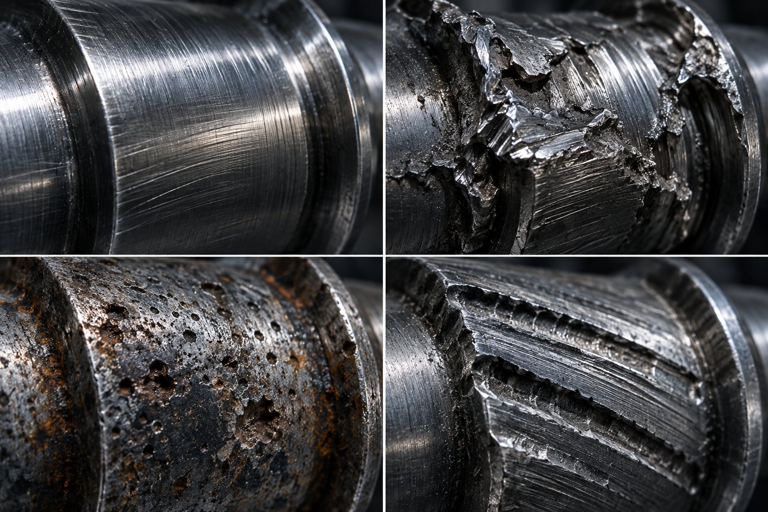
Four distinct mechanisms account for virtually all degradation in plasticating screws and barrels: abrasive wear, adhesive wear, corrosive wear, and erosive wear. Each produces a unique visual signature on removed hardware and a distinct operational fingerprint on the production floor. Here's how to tell them apart.
Abrasive Wear Patterns and Their Symptoms
This is the most common wear type in plastics processing equipment — and the one most operators encounter first. Abrasive wear extruder screw damage occurs when hard particles in the melt stream physically grind material away from the screw flights and barrel bore. Glass fibers, mineral fillers like calcium carbonate and talc, recycled materials carrying metal or sand contaminants, and even high-viscosity unfilled polymers under shear all act as cutting agents that remove metal from softer surfaces.
Glycon Corp.'s Jeff Kuhman identifies abrasive wear as the most prevalent type in plastics machinery, noting that it can be minimal with unfilled, low-viscosity polymers but becomes significant when processing resins with fillers, additives, or regrind contaminants. The underlying principle is simple: hard materials remove material from softer surfaces, which is why flight lands are typically hard-faced with abrasion-resistant alloys.
What makes abrasive wear distinctive — both visually and operationally — is its gradual, predictable progression. You won't wake up to a sudden crisis. Instead, specific rate drifts downward week by week, and the screw flights, when finally pulled for inspection, tell a clear story.
- Visual signature on removed hardware: Smooth, polished wear surfaces on flight tips and barrel bore. Sharp machined edges become rounded and occasionally develop a mirror-like finish. Flight OD reduces uniformly along the screw length, though the transition zone usually shows the heaviest loss. Xtrutech notes that abrasive wear causes sharp machined corners to appear rounded, smooth, and occasionally polished — a telltale sign that distinguishes it from other mechanisms.
- Operational symptom fingerprint: Slow, steady output decline at constant RPM. Rising melt temperature that develops over weeks or months, not hours. Gradually increasing energy consumption per unit of output. Reject rates that creep higher rather than spike suddenly. Compensating adjustments — slightly higher screw speed, small backpressure tweaks — that temporarily mask the trend before the next round of adjustment becomes necessary.
The predictability of abrasive wear is actually an advantage for maintenance planning. Because the decline is linear and consistent, you can chart specific rate trends against screw hours or kilograms processed and forecast when the component will reach the replacement threshold — avoiding both premature changeouts and catastrophic run-to-failure scenarios.
Adhesive and Galling Wear Signatures
Adhesive wear is a fundamentally different animal. Instead of gradual material removal by hard particles, it involves direct metal-to-metal contact between the screw flight land and the barrel bore. When these surfaces touch under extreme pressure, microscopic welding occurs at contact points. As the screw continues to rotate, those micro-welds fracture, tearing material from one surface and transferring it to the other. The result is a rough, damaged surface that accelerates further contact — a self-reinforcing cycle that can escalate quickly.
Evidence of adhesive wear typically appears as a burr or "rolling over" of the trailing edge of the flight land, or as scored or missing hard-facing material on flight tops. The barrel bore at the corresponding location should also be checked for scoring or galling marks. Several conditions trigger this mechanism:
- Screw deflection from solids wedging: When unmelted material plugs the channel in the compression zone, the resulting asymmetric pressure pushes the screw off-center, forcing the flights into direct contact with the barrel wall.
- Poor screw-to-barrel alignment: Misalignment between the drive assembly and barrel causes the screw to ride against one side of the bore, creating a wear stripe rather than uniform contact.
- Incompatible metallurgy: Certain screw hard-facing alloys and barrel liner materials have a tendency to gall when paired together, especially softer alloys run against the hardest barrel-lining materials.
- Running without resin: Xtrutech highlights that screws left to rotate — particularly at high speeds — between production runs lose the molten-resin film that normally lubricates the screw-to-barrel interface, leading directly to adhesive wear.
- Visual signature on removed hardware: Rough, torn, or gouged surfaces on flight tips and barrel bore — the opposite of the polished finish left by abrasive wear. You may see material transfer (a buildup of screw metal on the barrel wall, or barrel liner material embedded in the screw flights). Score marks, deep scratches, and localized galling patches are common. Hard-facing material may be cracked, chipped, or entirely missing from affected flights.
- Operational symptom fingerprint: Sudden rather than gradual performance changes. Torque spikes and motor overloads that appear intermittently. Unusual noises — metallic scraping or vibration — from the barrel during operation. In severe cases, the screw can seize inside the barrel, requiring the entire assembly to be heated and carefully extracted. Production may run fine for days, then experience an abrupt disruption — a pattern that distinguishes adhesive wear from the slow fade of abrasion.
Corrosive and Chemical Wear Indicators
Some resins fight back chemically. Processing PVC, fluoropolymers, acetals (POM), and flame-retardant compounds releases acids and corrosive gases — hydrochloric acid from PVC, hydrofluoric acid from fluoropolymers, and formaldehyde from acetals — that attack metal surfaces at the molecular level. This corrosive barrel wear PVC operators frequently encounter is particularly insidious because it weakens the surface before mechanical wear even begins.
Corrosion is the gradual destruction of materials by chemical attack, where most atoms on the metal surface become oxidized, damaging the entire surface layer. This breakdown actually makes the surface vulnerable to subsequent mechanical wear — a one-two punch that can devastate components much faster than either mechanism alone. Resins in the fluoropolymer family and PVC aggressively attack components with a high iron matrix, making standard nitrided steel barrels inadequate for sustained processing of these materials.
- Visual signature on removed hardware: Pitting, cratering, and roughened bore surfaces — distinctly different from the smooth polish of abrasive wear or the gouges of adhesive wear. The damage often appears as a uniform degradation of the surface finish, with the barrel liner taking on a dull, etched appearance. In severe cases, you'll see visible pitting deep enough to trap polymer, creating hang-up spots that degrade subsequent melt quality. The screw root and flight flanks in the metering zone — where melt temperatures peak — tend to show the worst corrosive damage.
- Operational symptom fingerprint: Contamination of the melt stream with metallic particles, producing dark specks or discoloration in finished parts. A gradual roughening of extrudate surface finish. Rising reject rates that correlate with processing temperature — higher melt temperatures accelerate acid release and corrosion rates. In extreme cases, barrel wall thinning from corrosion can affect temperature control, as the thinner wall changes the thermal path between heater bands and the melt.
Erosive Wear from High-Velocity Melt Flow
Erosive wear is the most localized of the four mechanisms. It occurs wherever molten polymer accelerates through a restricted passage — flight tips, barrier flight clearances, mixing element edges, and the narrow gaps in distributive mixing sections. The high-velocity melt stream carries abrasive particles or simply exerts enough hydrodynamic force to remove material from metal surfaces at the point of flow acceleration.
You'll encounter erosive wear most often in screws with barrier flights or specialized mixing elements, where tight clearances create localized flow velocities significantly higher than those in the main screw channel. Filled resins amplify the effect because glass fibers and mineral particles carried at high velocity act like a sandblasting stream focused on a small area.
- Visual signature on removed hardware: Localized grooves, channels, or washout patterns concentrated at specific geometric features — the leading edge of barrier flights, the tips of mixing pins, or the entry points of mixing slots. Unlike abrasive wear, which tends to produce broad, uniform material loss, erosive wear creates distinct patterns that mirror the flow path. The damage often looks like water erosion on a riverbank: smooth, curved channels carved into the metal surface at predictable locations.
- Operational symptom fingerprint: Symptoms may not appear in overall throughput metrics until the erosion is severe. Early indicators include a decline in mixing quality — color inconsistency or incomplete additive dispersion — because the eroded mixing elements lose their geometric precision. In barrier screws, erosion of the barrier flight clearance allows solid material to pass into the melt channel prematurely, producing gels and unmelted specks similar to what you'd see from general compression-zone wear. Pressure stability may deteriorate before output rate drops measurably.
Correct wear-type identification determines whether standard nitrided steel, bimetallic liners, or specialized wear-resistant coatings are needed for the replacement or repair — choosing the wrong metallurgy means paying for a fix that won't last.
In practice, most screws and barrels show evidence of more than one wear type when removed from service. A glass-filled PVC compound, for example, delivers simultaneous abrasive and corrosive attack — the glass fibers grind while the hydrochloric acid etches. Flame-retardant nylon combines mineral-filler abrasion with chemical corrosion from decomposition byproducts. Reading the physical evidence on the removed hardware — smooth polish versus rough gouges versus chemical pitting versus localized washout — tells you which mechanism dominated. And that diagnosis drives every downstream decision, from alloy selection for hard-facing to the choice between a standard bimetallic barrel liner and a corrosion-resistant nickel-based alloy.
The wear type shapes what you buy. But the question of how bad the wear actually is — and whether it's truly screw barrel degradation or something else mimicking the same symptoms — requires a different kind of evidence. That's where measurement tools and diagnostic KPIs separate educated guesses from confirmed, actionable data, especially when the symptoms differ between extrusion and injection molding platforms.
Injection Molding vs Extrusion Wear Symptom Profiles
Extrusion lines and injection molding machines both rely on screws and barrels to plasticize polymer — but they do it in fundamentally different ways. Extrusion is a continuous process: the screw rotates in one direction, pushing an uninterrupted melt stream through a die. Injection molding is cyclical: the screw rotates to plasticize a shot, then acts as a ram to inject that shot into a mold. These operational differences mean that wear shows up through entirely different symptom sets. Diagnosing injection molding screw wear using an extrusion-centric checklist — or vice versa — leads to missed signals and wasted troubleshooting time.
Extrusion-Specific Wear Symptoms
Because extrusion runs continuously, its wear symptoms tend to present as gradual, trend-based shifts in process KPIs rather than discrete event-level anomalies. The most telling indicator is a declining specific rate — output per RPM — which drops steadily as clearance increases and more polymer leaks backward over worn flights. Predictive maintenance data from continuous extrusion monitoring shows that tracking output at rated RPM against a baseline reveals wear progression weeks before it becomes visible in product quality.
Other symptoms unique to extrusion barrel and screw degradation include:
- Surging at the die: Periodic pressure fluctuations that produce dimensional variation in the extrudate — wall thickness swings in pipe, gauge bands in film, or weight-per-foot inconsistency in profiles. Surging that wasn't present at startup but develops over months of run time strongly suggests worn clearances rather than a process setup issue.
- Increased screen-pack loading frequency: A worn screw delivers a less homogeneous melt with more unmelted particles, gels, and degraded polymer. These contaminants clog screen packs faster, forcing more frequent changeouts. If your screen change interval has shortened by 20% or more without a resin change, suspect the screw.
- Die-land buildup and plate-out: Degraded melt quality from worn components deposits volatile residues and partially degraded polymer on die land surfaces, creating buildup that requires more frequent cleaning and produces streaking on the product surface.
Extrusion screw wear also tends to be more uniform along the screw length than what you'll find in injection molding. The screw rotates continuously in one direction, so every flight sees consistent contact with the barrel wall over time. That said, the transition zone still wears fastest due to the high pressures and abrasive partially melted solids discussed in the zone-by-zone breakdown above.
Injection Molding-Specific Wear Symptoms
Injection molding introduces a completely different symptom vocabulary. The cyclical nature of the process — plasticize, inject, hold, cool, repeat — creates discrete, shot-level data points that reveal wear through variability rather than gradual trends. If you're running a screw barrel injection molding setup and noticing any of the following, wear should be on your differential diagnosis list:
- Shot-to-shot weight inconsistency: When clearances are tight, each plasticating cycle delivers a repeatable volume of melt in front of the screw tip. As clearances open, polymer leaks back over the flights during injection, reducing the effective shot volume unpredictably. You'll see part weights scatter beyond normal process capability — and statistical process control charts start flagging out-of-spec readings more frequently.
- Cushion loss or instability: The cushion — the small pad of melt left in front of the screw at the end of injection — should remain consistent shot to shot. A shrinking or erratic cushion suggests material is leaking backward past worn flights or a degraded check valve during the injection phase.
- Increased plasticating time: A worn screw takes longer to recover (rotate forward to prepare the next shot) because its pumping efficiency has dropped. If recovery time has crept up by 10-15% without any change in shot size, backpressure, or resin, that's a meaningful signal.
- Short shots despite constant settings: Perhaps the most frustrating symptom. The machine runs the same program it always has, yet molds don't fill completely. Santa Fe Machine Works identifies short shots as one of the top defects caused by worn screws, valves, or barrels — noting that equipment wear introduces inconsistencies that cannot be corrected through machine settings alone.
Beyond short shots, common injection molding defects linked to worn components include warping from inconsistent packing pressure, sink marks from insufficient hold pressure delivery, flash from pressure spikes caused by erratic screw behavior, flow lines from uneven melt temperature, and burn marks from material degradation in worn clearance areas. Many of these defects get initially blamed on process parameters when the real culprit is mechanical wear.
The Check Valve Trap: Misdiagnosing Valve Wear as Barrel Wear
Here's where injection molding diagnosis gets tricky — and where many maintenance teams spend money on the wrong repair. The check valve (non-return valve) sits at the screw tip and prevents melt from flowing backward during injection. When it wears, the symptoms look almost identical to screw and barrel clearance wear: cushion loss, shot weight variation, short shots, and increased plasticating time.
A simple diagnostic test can help you tell them apart. With the machine at operating temperature and a full shot plasticized in front of the screw, hold the screw in its forward position under injection pressure without injecting into the mold (an "air shot" against an empty barrel or with the nozzle blocked). Watch the screw position indicator. If the screw creeps forward — meaning material is leaking past the check valve — you've confirmed valve leakage. If the screw position remains stable but you're still experiencing cushion instability during actual molding cycles, the problem is more likely barrel clearance leakage occurring during the dynamic plasticating phase rather than during the static injection hold.
This distinction saves real money. A check valve replacement is a fraction of the cost and downtime of a full screw or barrel change. Skipping this test and jumping straight to a screw and barrel replacement is one of the most common — and most expensive — misdiagnoses in injection molding maintenance.
Cross-Platform Symptoms Shared by Both Processes
Despite their operational differences, extrusion and injection molding share a core set of wear indicators that transcend platform type. Rising melt temperature at constant settings, increasing energy consumption per unit of output, and visual defects in finished products (streaking, surface roughness, discoloration) appear in both processes because they stem from the same underlying physics — enlarged clearance generating excess shear heat and reduced pumping efficiency.
The table below provides a side-by-side comparison so you can quickly identify which diagnostic path applies to your specific equipment:
| Symptom Category | Extrusion-Specific | Injection Molding-Specific | Shared |
|---|---|---|---|
| Output / Throughput | Declining specific rate (kg/hr per RPM); surging at the die | Shot weight inconsistency; short shots; increased plasticating time | Reduced output efficiency requiring operator compensation |
| Pressure Behavior | Melt pressure instability; increased screen-pack loading | Cushion loss or instability; erratic injection pressure profile | Pressure fluctuations beyond historical norms |
| Thermal Indicators | Discharge melt temperature trending upward over weeks | Shot-to-shot melt temperature variation | Rising melt temperature at constant barrel setpoints; increased energy consumption (kWh per unit) |
| Product Quality | Die-land buildup; gauge variation in film or sheet; surface roughness on profiles | Warping; sink marks; flash; flow lines; burn marks | Streaking; color inconsistency; unmelted particles; gels; surface defects |
| Confounding Factors | Screen pack clogging; die wear; breaker plate erosion | Check valve (non-return valve) wear mimicking barrel clearance issues | Heater band failure; thermocouple drift; inconsistent resin lots |
Notice the "Confounding Factors" row at the bottom. Every symptom in this table has at least one non-wear explanation that can mimic it convincingly. That overlap is precisely why visual observation and symptom pattern recognition, while essential starting points, are never enough on their own. Translating a suspected wear problem into a confirmed, actionable diagnosis requires hard numbers — bore measurements, screw OD data, and tracked KPIs that quantify exactly how far components have drifted from their original specifications.
Confirming Wear Through Measurement and Diagnostic KPIs
Symptom patterns and production-floor observations get you to the right neighborhood — but they don't give you an address. You can suspect worn clearances based on declining specific rate, rising melt temperature, and visual defects in your product. You might even narrow the problem to a specific screw zone or wear type. Yet none of those observations tell you the one thing you need before signing a purchase order: exactly how many thousandths of an inch the bore has enlarged, or how much flight OD the screw has lost. That answer comes only from physical measurement — the step that transforms an educated guess into confirmed, actionable data.
Barrel Bore Measurement Methods and Acceptance Criteria
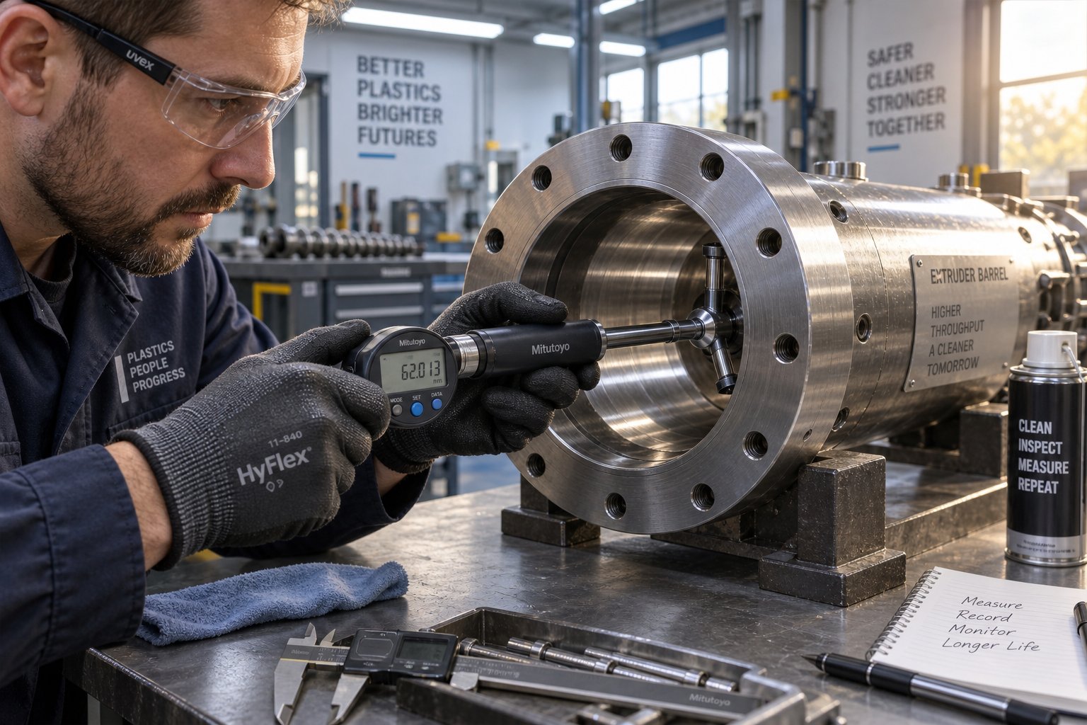
Barrel wear measurement starts with a precision bore gauge — a telescoping instrument inserted into the barrel bore to capture internal diameter readings at multiple points along the barrel's length. The process sounds simple, but getting reliable numbers requires careful preparation and technique.
Before measuring, clean the barrel thoroughly to remove all residual polymer. Even a thin film of plastic clinging to the bore wall will throw off readings and can damage the measuring head of a precision bore gauge. Allow the barrel to cool to ambient temperature — a hot barrel expands, producing artificially large ID readings that don't reflect the true wear state. Set up the bore gauge using micrometers calibrated to the nominal barrel diameter, then insert the gauge from the discharge end.
A critical procedural detail that many technicians overlook: when measuring a barrel still mounted on the machine, concentrate on the stroke area and the transition section — this is the major area of concern for injection barrels. Do not push the gauge past the feed port opening, as the measuring head can drop into the feed port slot and sustain serious damage. Measure in one-inch increments, pulling the gauge slowly toward the discharge end, and record each reading to build a complete wear profile along the barrel length.
What constitutes "too worn"? The widely referenced industry guideline is straightforward: when the radial clearance between screw and barrel exceeds twice the original as-new specification, the barrel generally warrants replacement or re-lining. For context, here are typical as-new diametral clearances (total clearance, not per side) by screw diameter:
| Nominal Screw Diameter | Typical As-New Diametral Clearance | Replacement Threshold (2x As-New) |
|---|---|---|
| 1.0" (25 mm) | 0.002" - 0.003" | 0.004" - 0.006" |
| 1.5" (38 mm) | 0.003" - 0.004" | 0.006" - 0.008" |
| 2.0" (50 mm) | 0.004" - 0.005" | 0.008" - 0.010" |
| 2.5" (63 mm) | 0.005" - 0.006" | 0.010" - 0.012" |
| 3.5" (90 mm) | 0.006" - 0.008" | 0.012" - 0.016" |
| 4.5" (114 mm) | 0.008" - 0.010" | 0.016" - 0.020" |
| 6.0" (150 mm) | 0.010" - 0.012" | 0.020" - 0.024" |
These values serve as general guidelines — the SPI Dimensional Guidelines provide more detailed reference tables for specific machine types and barrel constructions. Keep in mind that clearances on the tighter end of the range apply to precision applications like medical tubing or optical film, while the wider end suits less demanding commodity processing. The key isn't any single number — it's the trend. A barrel bore gauge measurement taken today means little in isolation but becomes powerful when plotted against previous readings to reveal the rate of progression.
Screw OD and Root Diameter Inspection
While the barrel is a relatively simple cylinder to measure, screw wear inspection methods demand more patience and a different set of tools. Before measuring, remove all residual resin from the screw and place it on a clean, flat work surface. Start with a visual examination — look for obvious damage, pitting, cracks, or discoloration that indicates corrosive attack. If you have access to a granite surface plate, roll the screw across it and watch for bowing. A bent screw creates asymmetric barrel contact that accelerates wear on both components, and feeler gauges can quantify any deflection you observe.
For dimensional measurements, use an outside micrometer to capture three critical values at each zone along the screw:
- Flight OD (outer diameter): Place a parallel test bar spanning two adjacent flights and measure across it with the micrometer. This technique, recommended by Adams Engineers, compensates for the helical flight geometry and gives you an accurate OD reading. Compare to the nominal barrel bore size — the difference is your radial clearance.
- Root diameter: Measure the diameter at the bottom of the screw channel in each zone. Root erosion in the metering section reduces pumping capacity, while root wear in the feed zone alters the compression ratio and disrupts solids conveying.
- Flight width (land width): Measure the flat top surface of the flight at multiple points. A flight land that has narrowed significantly from its original dimension has lost sealing area against the barrel wall, increasing leakage flow even if the OD itself hasn't changed dramatically.
The real diagnostic power emerges when you compare measurements across zones. Uniform OD loss along the entire screw length points to general abrasive wear from the resin being processed. Heavy OD loss concentrated in the transition zone, with the feed and metering sections relatively intact, suggests aggressive abrasion from partially melted filled compounds — exactly the pattern described in the zone-by-zone analysis. OD loss isolated to the metering zone, especially with evidence of pitting or surface roughness, indicates corrosive attack at peak melt temperatures. Each pattern tells a story about what caused the damage, guiding your material selection for the replacement component.
The best maintenance programs don't wait for a crisis to pull the screw and measure. Recording measurements at standard intervals allows you to create a wear profile that identifies the expected lifespan of each component. Over time, you build a predictive picture: you know this particular screw running this particular resin will lose approximately X thousandths of flight OD per thousand hours of operation, and you can plan replacement before performance becomes unacceptable.
Tracking Specific Rate and Discharge Temperature as Ongoing KPIs
Physical measurement of bore and screw dimensions requires downtime — you need to cool the barrel, pull the screw, and spend hours with gauges and micrometers. That's essential, but it's a snapshot. Between those snapshots, two process KPIs provide continuous, real-time surveillance of wear progression without ever stopping the machine.
The first is specific rate: output (lb/hr or kg/hr) divided by screw RPM. Calculating it is straightforward — weigh the output over a timed interval during stable production, divide by the screw speed, and record the result. Do this for each product you run regularly, and plot the values over time. A new screw and barrel will establish a consistent baseline. As clearances increase, specific rate declines because more material leaks backward over the flights instead of being conveyed forward. The beauty of this KPI is its sensitivity: specific rate begins dropping well before visual defects appear in the product, giving you weeks or months of lead time to plan a maintenance event.
Imagine two identical extruders running the same HDPE compound. Machine A delivers 42 lb/hr per RPM when its screw and barrel are new. Six months later, that number has drifted to 39 lb/hr per RPM — a 7% decline. The operator compensated by bumping screw speed from 80 to 86 RPM to maintain total output, so daily production numbers looked fine. But the specific rate trend revealed the truth: clearances were opening, and the machine was working harder to deliver the same result. Without that KPI, the wear would have gone undetected until melt quality deteriorated enough to produce visible defects — likely several more months down the road.
The second KPI is discharge melt temperature. As discussed earlier, worn clearances generate excess shear heating from back-leakage over enlarged flight gaps. Tracking melt temperature at the die or nozzle — using an immersion thermocouple or infrared probe, not relying solely on barrel zone thermocouples — provides an independent thermal indicator of clearance condition. A rising melt temperature trend at constant barrel setpoints and screw speed mirrors the specific rate decline and serves as a corroborating data point.
Together, these two KPIs form a powerful early-warning system. Specific rate tells you the screw is losing pumping efficiency. Discharge melt temperature tells you the clearance is generating excess shear heat. When both trends move in the same direction simultaneously — specific rate falling while melt temperature rises — you have a strong, quantitative case that wear has progressed to a point requiring physical inspection and measurement.
Measurement data should always be correlated with symptom observations — neither alone provides a complete diagnosis. A bore reading means little without knowing the production symptoms it's producing, and a symptom list means little without numbers confirming the root cause.
Hard numbers and confirmed clearance data give you the confidence to act — but only if you're certain that the symptoms and measurements are actually pointing to screw and barrel wear rather than a dozen other problems that produce nearly identical signals. That critical step — systematically ruling out the imposters — is where many maintenance teams either save or waste thousands of dollars.
Ruling Out Problems That Mimic Screw and Barrel Degradation
You've tracked specific rate. You've watched melt temperature climb. You've even seen visual defects that match every textbook description of worn clearances. The temptation is strong to order a new screw and barrel, schedule the downtime, and move on. But here's the uncomfortable truth: dozens of non-wear problems produce symptoms that are virtually identical to screw barrel wear symptoms. Pulling a perfectly serviceable screw — only to find it measures within spec — is an expensive lesson in the importance of differential diagnosis. This screw barrel troubleshooting guide walks through the most common imposters and provides a systematic workflow to rule them out before committing to a hardware replacement.
Process Issues That Mimic Screw and Barrel Wear
Several everyday process problems create the exact same production-floor signals as worn components. The difference? They're fixable in minutes or hours, not days — and they cost a fraction of what new hardware runs.
Hopper bridging and inconsistent feeding. When pellets bridge across the hopper throat or feed inconsistently due to moisture, fines, or additive buildup, the screw starves intermittently. The result looks a lot like feed zone wear: fluctuating output, surging, and throughput that doesn't match historical norms at the same RPM. Test for it by observing the feed throat directly during production. Tap the hopper walls. Switch to a different resin lot. If output stabilizes, the problem was never the screw.
Inadequate feed throat cooling. The feed throat needs active cooling to prevent pellets from softening prematurely and sticking to metal surfaces. When cooling water flow drops — due to a scaled heat exchanger, a partially closed valve, or a failed pump — pellets begin to melt too early, forming a sticky plug that chokes solids conveying. The symptoms mimic feed zone wear almost perfectly: reduced throughput, erratic feeding, and a screw that seems to have lost its ability to grip pellets. Check cooling water temperature and flow rate before suspecting the hardware.
Degraded heater bands creating cold spots. A failed or underperforming heater band in the transition zone starves that section of the thermal energy needed to melt polymer. The result? Unmelted particles in the product, elevated melt temperature in downstream zones as the material compensates, and melt quality problems that look identical to compression-zone wear. Uneven barrel heating from faulty heaters can also cause the barrel to expand asymmetrically, creating localized contact between the screw and barrel wall — which then causes real adhesive wear if left uncorrected. Check heater band continuity and amperage draw zone by zone. A heater drawing zero amps is obviously dead, but one drawing 30% less than its rated output is quietly underperforming and may produce subtle symptoms that develop over weeks.
Incorrect screw speed or back-pressure settings. This one sounds too simple to fool experienced operators, but it happens. A process recipe that was altered during a trial run and never reset, a back-pressure value that drifted after a controller calibration, or a speed setpoint accidentally changed by one digit — any of these can shift output, melt temperature, and part quality in ways that parallel wear-induced degradation. Always verify current machine settings against the documented baseline before launching a wear investigation.
Component Wear That Masquerades as Screw Barrel Wear
Sometimes the hardware genuinely is worn — just not the screw or barrel. Several peripheral components produce overlapping symptoms that lead maintenance teams down the wrong path.
Check valve (non-return valve) wear in injection molding. This is the single most common misdiagnosis in injection molding screw wear investigations. As discussed in the platform-specific section, a worn check ring allows melt to leak backward during injection, causing cushion instability, shot weight variation, and short shots — symptoms indistinguishable from barrel clearance leakage during a normal production cycle. Experts at Asaclean note that an improperly functioning non-return valve allows material to slip past, limiting control over consistent cavity packing and making it difficult to maintain part tolerances. The check ring is a wear component with a much shorter service life than the screw and barrel it's mounted on. Always inspect and rule out valve wear first — it's faster, cheaper, and resolves the problem far more often than operators expect.
Breaker plate erosion. The breaker plate sits between the screw tip and the die, supporting the screen pack and helping convert rotational melt flow into linear flow. Over time, the holes in the breaker plate enlarge from abrasive and erosive wear, reducing its ability to hold back-pressure. The operational symptom — lower head pressure and reduced pumping resistance — mimics metering-zone screw wear. Pull the breaker plate and inspect the hole dimensions against the original specification. Eroded holes will appear visibly enlarged or oval-shaped.
Screen pack clogging. A partially clogged screen pack restricts flow and raises head pressure, forcing the operator to increase screw speed to maintain output. The rising energy consumption and apparent loss of efficiency look like general clearance wear. The tell? Symptoms appear relatively suddenly (over hours or a shift, not weeks) and correlate with time since the last screen change. Replace the pack. If specific rate returns to baseline, the screw is fine.
Die wear. Worn die lips or land surfaces create dimensional variation and surface defects on the extrudate that can be mistaken for melt quality issues from screw degradation. Die wear tends to produce localized defects — one side of the profile runs thicker than the other, or a specific section of film shows gauge variation — rather than the uniform quality decline associated with screw and barrel wear. Inspect die surfaces for erosion, particularly at flow restriction points.
A Step-by-Step Extruder Screw Wear Diagnosis Workflow
Avoid the temptation to jump straight to hardware inspection. The following sequence moves from the quickest, cheapest checks to the most time-intensive, ensuring you rule out simple causes before committing to a screw pull. Think of it as a funnel — each step either eliminates a non-wear explanation or builds the case that genuine wear is the problem.
- Verify process settings against baseline. Compare current screw speed, barrel temperatures, back-pressure, and feed rate settings against the documented recipe for the product being run. Confirm that no unauthorized changes have been made. This takes five minutes and eliminates one of the most common false alarms.
- Inspect ancillary equipment. Check the hopper for bridging, verify feed throat cooling water flow and temperature, inspect the screen pack and breaker plate condition, and — for injection molding — perform the check valve leakage test described earlier. Each of these inspections can be completed during normal production or a brief pause.
- Check heater band and thermocouple function. Measure amperage draw on every heater band and compare to rated values. Verify thermocouple readings against a handheld pyrometer or calibration standard. A single failed heater or drifted thermocouple can create symptoms that perfectly mimic zone-specific wear.
- Run specific rate and melt temperature KPI checks. Calculate current specific rate and compare to your established baseline. Measure discharge melt temperature with an independent probe. If specific rate is within 5% of baseline and melt temperature is stable, the screw and barrel are likely still serviceable — look elsewhere for the root cause of your symptoms.
- Perform physical measurement of bore and screw dimensions. Only after steps 1 through 4 have failed to identify a non-wear cause should you schedule the downtime to cool the barrel, pull the screw, and take bore gauge and micrometer measurements. At this point, you've already ruled out the quick fixes and have strong KPI evidence supporting a wear diagnosis — making the investment in downtime justified and the measurement results immediately actionable.
This workflow saves money by preventing unnecessary screw and barrel replacements. A complete set of replacement components for a mid-size extruder can easily run $15,000 to $40,000 or more, plus multiple shifts of lost production during the changeover. Spending an hour running through steps 1-4 before pulling that trigger is one of the highest-return activities a maintenance team can perform.
One final calibration point worth addressing: are screw holes normal wear and tear, or do they signal something more serious? Minor surface pitting, light scoring, and shallow marks on the screw root or flight flanks are common after extended service and typically represent acceptable cosmetic wear that doesn't affect performance. Uniform, shallow surface roughening from abrasive contact with filled resins is expected behavior — not a reason to condemn the screw. What isn't normal: deep pitting that exposes base metal beneath the hard-facing, cracks propagating along flight roots, chunks of hard-facing material missing from flight tips, or localized gouging patterns that suggest metal-to-metal contact. These signs indicate active, progressive damage that will worsen quickly. The distinction matters because over-reacting to cosmetic wear wastes money on premature replacements, while under-reacting to structural damage risks catastrophic failure during production.
The most expensive screw and barrel replacement is the one that didn't need to happen — always exhaust the diagnostic funnel before committing to new hardware.
When the differential diagnosis confirms genuine wear — settings verified, ancillary components cleared, KPIs pointing in the wrong direction, and measurements showing clearances beyond threshold — the question shifts from "is it worn?" to "what do we do about it?" The answer isn't always a full replacement. Depending on the severity and type of wear confirmed through this diagnostic process, resurfacing or rebuilding may restore full performance at a fraction of the cost and downtime.
Choosing the Right Screw Barrel Repair Options After Confirming Wear
Your bore gauge readings are in hand. The differential diagnosis cleared every non-wear suspect. Specific rate has dropped 12% from baseline, discharge melt temperature is running 15 degrees above historical norms, and the screw OD measurements show 0.008 inches of flight loss concentrated in the transition and metering zones. The diagnosis is confirmed: you're dealing with real, measurable screw and barrel degradation. The next decision — repair, resurface, or replace — carries significant cost, downtime, and performance implications. Getting it wrong means either overspending on components that could have been salvaged, or under-investing in a patch job that fails within months.
When to Repair vs Resurface vs Replace
There's no universal answer. The right remediation path depends on several intersecting factors that you need to evaluate together, not in isolation:
- Severity of wear: Moderate flight OD loss with intact root geometry and no structural cracks is a strong candidate for resurfacing. Severe root erosion that has undermined the flight substrate, or barrel bore enlargement that has worn through the bimetallic liner into base steel, typically demands replacement. Experienced screw manufacturers note that if careful consideration of wear monitoring is ignored, screw wear can become so extreme that reliable repair is difficult or impossible.
- Wear type: Abrasive wear that has smoothly reduced flight dimensions is straightforward to rebuild with hard-facing. Adhesive wear that has torn and galled surfaces requires more extensive preparation before resurfacing. Corrosive damage with deep pitting may compromise the base metal's integrity to the point where welding onto it produces an unreliable bond.
- Cost comparison: Rebuilding a worn screw typically costs a fraction of the price of a new replacement — often 40-60% of new-component cost depending on the severity of work required. For high-performance or custom-designed screws, the savings are even more significant because the original design geometry is preserved.
- Production downtime considerations: A rebuild on an existing screw can often be turned around faster than manufacturing a new custom component from scratch. Plants that keep a spare screw in inventory can send the worn unit out for rebuilding while the spare keeps the line running — eliminating downtime from the equation entirely.
The following table maps each remediation option against its relative cost, typical turnaround, and the wear scenarios where it performs best. Use it as a starting framework for conversations with your maintenance team and component suppliers.
| Remediation Option | Relative Cost | Typical Turnaround | Best-Fit Wear Scenarios |
|---|---|---|---|
| Alloy spray welding and wear-resistant surface treatment | 30-50% of new | 1-3 weeks | Moderate flight OD loss from abrasive wear; corrosion-damaged surfaces needing hard, chemical-resistant rebuilding; screws and extrusion barrels where original geometry is sound but surface hardness has degraded |
| Complete re-screwing (new flights welded onto existing core) | 50-70% of new | 2-4 weeks | Severe flight wear with significant root erosion; screws requiring design changes (new mixing elements, altered compression ratio) |
| Barrel re-lining (new bimetallic liner) | 40-60% of new barrel | 3-6 weeks | Bore enlargement beyond tolerance with liner wear-through; localized bell-mouthing that can be bored out and re-lined |
| Full screw replacement | 100% (baseline) | 4-8 weeks (custom); 1-2 weeks (stock) | Screws rebuilt 3+ times previously; catastrophic damage (bent, cracked, or seized); opportunity to upgrade screw design for better performance |
| Full barrel replacement | 100% (baseline) | 4-10 weeks | Severe bore enlargement through full liner thickness; barrel wall thinning from corrosion compromising structural integrity; opportunity to upgrade liner metallurgy |
Notice that alloy spray welding sits at the top of this table — not because it's always the right answer, but because it occupies the cost-effective sweet spot that applies to the largest share of real-world wear scenarios. Most screws pulled for inspection fall into the moderate wear category: flight OD has lost enough material to degrade performance, but the core geometry, root dimensions, and structural integrity remain sound. That's exactly where surface rebuilding delivers the best return on investment.
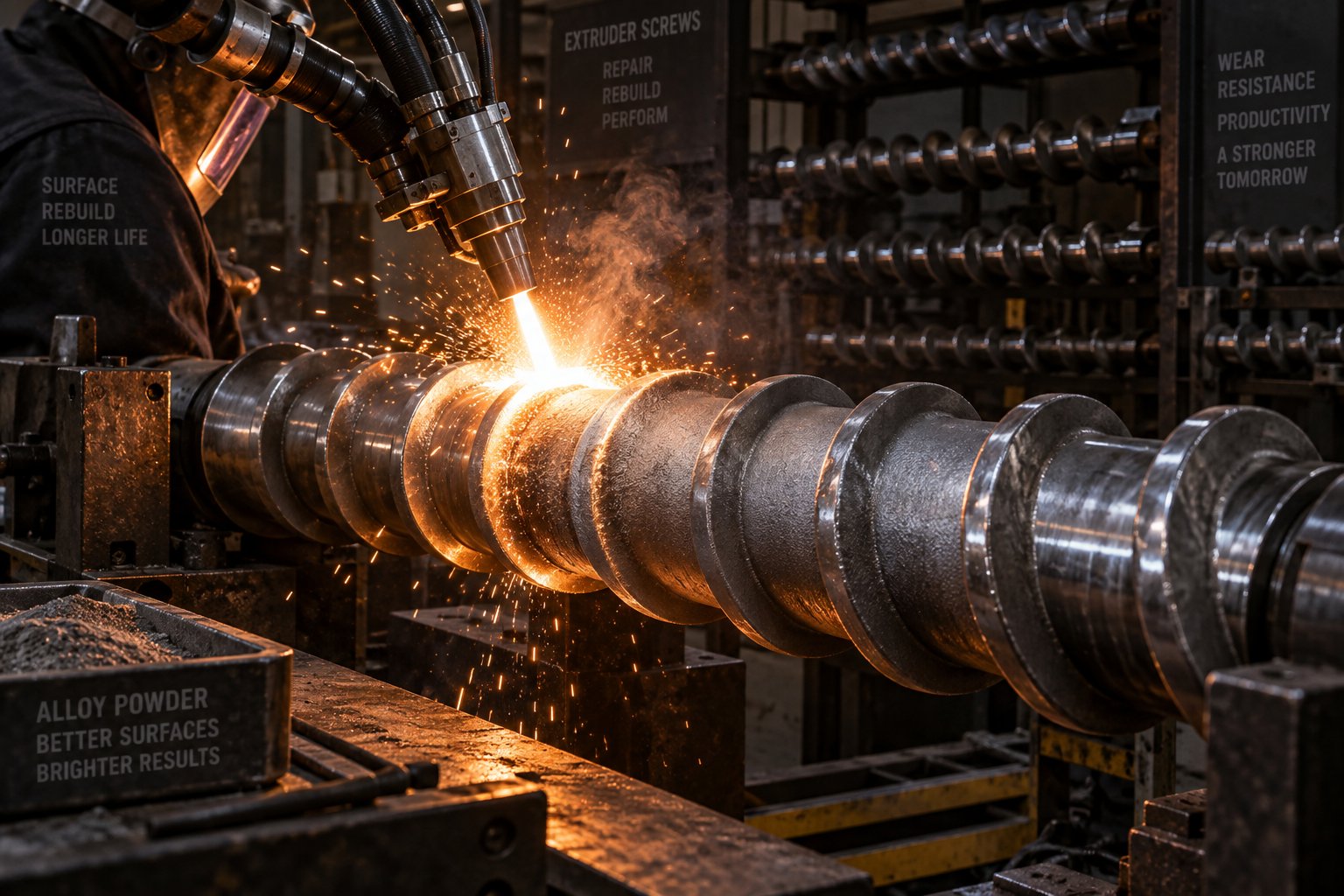
How Alloy Spray Welding Restores Worn Screws and Barrels
The concept behind alloy spray welding is elegant in its simplicity: rather than discarding a screw or barrel because its surface has degraded, you rebuild that surface with a material that's harder and more wear-resistant than the original. The process applies high-hardness alloy powder — typically tungsten carbide or nickel-based formulations — onto worn flight OD surfaces, screw roots, or barrel bores, then fuses the coating to the substrate at high temperature. The result is a metallurgical bond, not just a surface coating, that restores the component to its original dimensions while delivering surface hardness that can reach HRC 58-62 — significantly harder than the HRC 48-52 typical of standard nitrided steel.
What does that hardness improvement translate to in practice? Industry performance data shows that properly applied alloy spray welding coatings extend service life 3 to 5 times beyond ordinary nitrided components. The coating also improves melt flow characteristics by creating a smoother, more consistent contact surface — reducing polymer sticking, carbon buildup, and the degradation-related defects that worn surfaces promote.
The process follows a structured sequence when performed by experienced providers:
- Disassembly and cleaning: Residual polymer is removed through high-temperature annealing, and the screw or barrel is thoroughly cleaned to expose the base metal.
- Dimensional assessment: The wear condition is evaluated to determine whether resurfacing is feasible and cost-effective. Not every component benefits from rebuilding — excessive damage or base-metal compromise may make replacement the better path. A reputable supplier will tell you this honestly rather than proceeding with a rebuild that won't deliver lasting results.
- Surface preparation: Worn flights are ground to a uniform undercut diameter, providing a clean, consistent substrate for the welding process. For barrels, the bore is honed to restore roundness and straightness before any coating is applied.
- Alloy application and fusion: High-hardness alloy powder is sprayed onto the prepared surface using plasma transferred arc (PTA) welding or similar thermal spray methods. The coating fuses with the parent metal, creating a bond that resists delamination under the mechanical and thermal stresses of plasticating operation.
- Final machining: The rebuilt component is ground to original OEM tolerances, restoring flight OD, channel geometry, and surface finish to as-new specifications.
For operators dealing with screw wear, barrel wear, corrosion challenges, or shortened service life on extrusion and injection molding equipment, providers like NANHAIYA offer alloy spray welding and wear-resistant surface treatment services designed to restore components and extend their operational lifespan. Matching the coating alloy to the specific wear mechanism — abrasion-resistant tungsten carbide for glass-filled resins, corrosion-resistant nickel-based alloys for PVC and fluoropolymer processing — is essential to getting lasting results rather than a short-lived patch.
One important caveat: reputable screw manufacturers typically state that a screw can be rebuilt three to four times, though experienced rebuilders have successfully restored screws six to eight times with high-quality welding practices and careful metallurgical management. Each rebuild cycle consumes some base-metal integrity, so tracking rebuild history alongside wear measurements helps you determine when a component has genuinely reached end-of-life versus when another resurfacing cycle is viable.
Preventing Recurrence with Proactive Monitoring
Restoring a worn screw or barrel to like-new condition only pays off if you don't repeat the same cycle of neglect that led to the damage. The weeks immediately after a repair or replacement represent your best opportunity to establish the baseline data that drives everything discussed in this guide.
Here's a practical prevention framework to implement the day a rebuilt or new component goes back into service:
- Establish baseline KPIs immediately. Record specific rate (output per RPM) and discharge melt temperature during the first stable production run with the restored components. These are your reference points for all future trend monitoring. Document them formally — don't rely on memory or informal notes.
- Schedule regular barrel bore measurements. Depending on the abrasiveness of your resin portfolio, quarterly or semi-annual bore checks using the measurement protocol described earlier keep you ahead of the wear curve. Plot the readings over time to identify the rate of progression — it's far easier to predict the next maintenance window from a trend line than from a single snapshot.
- Track specific rate trends continuously. Make specific rate calculation a weekly or even shift-level habit for critical production lines. A 2-3% decline triggers a closer look at process variables. A sustained 5%+ decline initiates the differential diagnosis workflow to determine whether the root cause is wear, process drift, or ancillary equipment degradation.
- Match screw and barrel metallurgy to the resin being processed. This is where many plants fall short. Running a standard nitrided steel screw on glass-filled nylon, or a non-corrosion-resistant barrel on PVC, guarantees accelerated wear regardless of how new the components are. Review the wear-type analysis from your most recent inspection and ensure that the replacement or rebuilt component's alloy and surface treatment match the dominant wear mechanism in your application.
- Maintain a spare screw program. Having a rebuilt or new spare screw on the shelf transforms maintenance from a reactive emergency into a planned swap. Send the worn screw out for alloy spray welding while the spare keeps your line running — zero lost production, and you always have a serviceable backup ready.
Symptom literacy combined with measurement discipline and timely resurfacing or replacement is the most cost-effective strategy for managing screw and barrel wear across the equipment lifecycle — catching problems early, confirming them with data, and choosing the right remediation path every time.
The entire diagnostic journey this guide has walked through — from the first production-floor red flags, through zone-level and wear-type identification, platform-specific symptom profiling, quantitative measurement confirmation, differential diagnosis, and finally remediation — follows a single principle: don't replace until you've confirmed. Confirm the symptoms are real. Confirm they point to wear, not a process issue. Confirm the measurements support the diagnosis. And then confirm that your chosen repair path matches the type and severity of damage the data revealed. That discipline turns screw and barrel maintenance from a reactive cost center into a managed, predictable investment that keeps your production lines running at the performance levels your customers expect.
Frequently Asked Questions About Screw Barrel Wear Symptoms
1. What are the earliest signs of screw and barrel wear in an extruder?
The earliest and most reliable sign is a declining specific rate — output (kg/hr) divided by screw RPM — tracked over time against a baseline. Even a sustained 5-7% drop signals that clearances are widening and polymer is leaking backward over worn flights. Other early indicators include a gradual rise in discharge melt temperature at constant barrel setpoints and subtle melt quality shifts like surface roughness or faint streaking. These operational signals typically appear weeks or months before physical inspection reveals measurable dimensional changes, making daily KPI tracking a frontline detection tool.
2. How do you tell the difference between screw wear and barrel wear?
Screw wear primarily causes uniform, gradual output decline because eroded flight tips can no longer seal against the barrel wall. When inspected, you'll see reduced flight OD and rounded or ragged flight lands. Barrel wear tends to be more localized — bell-mouthing at the feed throat or bore enlargement in the transition zone — and often produces zone-specific surging or temperature control anomalies. A strong clue pointing to barrel wear is poor performance persisting even after installing a brand-new screw. Measuring both bore ID and screw OD together is the only way to confirm which component, or whether both, have exceeded tolerance.
3. Can screw barrel wear symptoms be confused with other machine problems?
Yes, and this misdiagnosis is common and costly. Hopper bridging, failed heater bands, inadequate feed throat cooling, and incorrect process settings all mimic wear symptoms like output loss and melt defects. In injection molding, worn check valves (non-return valves) produce cushion instability and short shots nearly identical to barrel clearance issues. A systematic differential diagnosis — verifying settings, inspecting ancillary equipment, and running KPI checks before pulling the screw — prevents unnecessary hardware replacements that can cost tens of thousands of dollars.
4. How often should screw and barrel measurements be taken?
Measurement frequency depends on resin abrasiveness and production volume. For lines processing glass-filled or mineral-filled compounds, quarterly bore gauge readings and screw OD checks are recommended. Less abrasive unfilled polymers may only require semi-annual inspections. Between physical measurements, tracking specific rate weekly and discharge melt temperature every shift provides continuous surveillance. Recording all data creates a trend line that predicts when components will reach the replacement threshold — typically when radial clearance exceeds twice the original as-new specification.
5. Is it better to repair a worn screw and barrel or replace them entirely?
It depends on wear severity, wear type, and base-metal integrity. Moderate flight OD loss with sound root geometry is an excellent candidate for alloy spray welding, which rebuilds worn surfaces with hard, wear-resistant alloys at 30-50% the cost of new components. Services like NANHAIYA's alloy spray welding (nhyscrews.com) restore screws and barrels to OEM dimensions while improving surface hardness to HRC 58-62 — extending service life 3-5x beyond standard nitrided steel. Full replacement is warranted when root erosion is severe, the bimetallic liner has worn through to base steel, or the component has already been rebuilt multiple times.
Written by
Nanhaiya Technical Team
Zhoushan Nanhaiya Plastic Machinery Co., Ltd.
The Nanhaiya technical team supports screw and barrel manufacturing projects through application review, technical communication, custom manufacturing coordination, and production and quality control.
Discuss Your Application
Related Articles
More insights on screw barrel technology and plastics processing.

What Nobody Tells You About Screw Barrel For Plastic Machine Design
Oct 10, 2026
Learn how screw barrel for plastic machine design affects melt quality, throughput, and wear life. Covers geometry, resin matching, troubleshooting, and sourcing.
Read Article
Single Screw Extruder for Sheet: Stop Guessing, Start Specifying
Oct 9, 2026
Learn how to specify a single screw extruder for sheet production. Covers screw geometry, resin-specific processing, troubleshooting, and maintenance best practices.
Read Article
PE Pipe Extruder Machine: What Datasheets Won't Tell You
Oct 9, 2026
Learn how a PE pipe extruder machine works, key specs explained, material grade selection, maintenance tips, and buyer guidance beyond the datasheet.
Read ArticleLooking for something else?
Search by material, symptom or product and jump straight to the relevant page.
These are navigation suggestions based on keyword matching — not a quotation, not a delivery commitment, and not a substitute for engineering review. Final specification is confirmed by our engineers against your drawings and processed material.
Need help with screw barrel selection?
Share your machine model, processed material and application. Our team can help with pricing and technical support.