

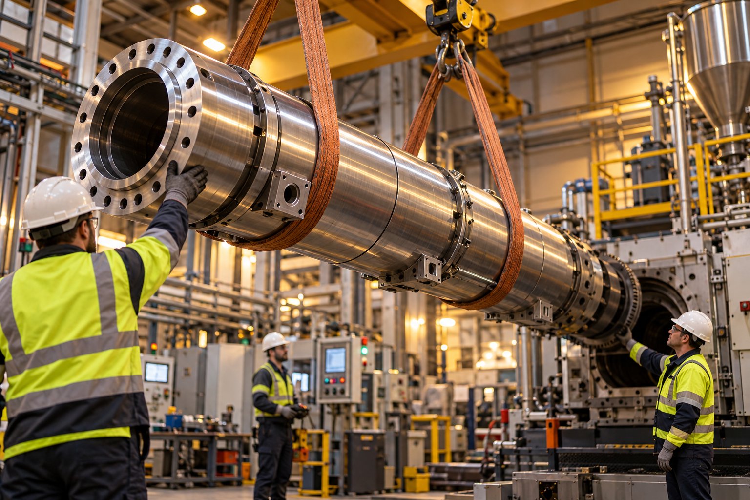
Why Plastic Extruder Barrel Replacement Demands a Strategic Approach
Plastic extruder barrel replacement is the process of removing a worn or damaged extruder barrel and installing a new or relined barrel to restore proper clearances, melt pressure, and product consistency. It spans the full lifecycle from early symptom identification through specification, sourcing, physical installation, and post-startup validation. Getting it right protects throughput, product quality, and your bottom line. Getting it wrong — or waiting too long — compounds costs in ways that rarely show up on a single line item.
What Is Extruder Barrel Replacement and Why It Matters
Every extruder barrel has a finite service life. Abrasive fillers grind away at bore surfaces. Corrosive resins attack alloy linings. Thousands of thermal cycles expand and contract the steel, gradually degrading dimensional integrity. The result is a widening gap between the screw flights and barrel wall — and that gap changes everything about how your screw plastic extruder performs.
Even small increases in flight-to-barrel clearance reduce pumping efficiency, allow melt to leak backward over the flights, and force operators to compensate with higher screw speeds and temperatures. As industry experts have noted, these compensations further accelerate wear, creating a cycle that quietly erodes output, inflates energy costs, and drives up scrap rates. Timely replacement of worn extruder barrels breaks that cycle before it reaches a crisis point.
Who This Resource Is For
Whether you manage a maintenance team, optimize processes as an engineer, or oversee daily plant operations, this guide walks you through every phase of a barrel replacement project — not just the wrench-turning part. Here is the journey you will follow:
- Diagnosis — recognizing the warning signs and measuring bore wear
- Quality impact analysis — understanding exactly how a worn extruder barrel degrades your end product
- Specification — measuring, documenting, and selecting the right material for your resin and process
- Decision-making — choosing between a new barrel, relining, or localized repair
- Execution — following a step-by-step removal and installation procedure
- Validation — confirming performance and establishing a monitoring baseline to extend service life
Scrap rates, dimensional drift, and rising discharge temperatures rarely point to a single dramatic failure. They creep in gradually — and the extruder barrel is often the overlooked culprit hiding behind those trends.
Warning Signs That Your Extruder Screw Barrel Needs Replacement
A worn extrusion barrel rarely announces itself with a sudden, dramatic failure. Instead, it whispers — through a slow decline in output, a creeping rise in energy consumption, and scrap bins that seem to fill a little faster each month. These symptoms overlap with dozens of other process issues, which is exactly why barrel wear goes undetected for so long. By the time it becomes obvious, the damage to your throughput and profitability is already significant.
Knowing what to look for — and how to measure it — separates a proactive replacement from an emergency shutdown.
Process Symptoms That Point to Barrel Wear
Imagine this scenario: your extruder has been running the same resin at the same settings for months, and yet your operators keep nudging the screw speed upward just to hold the target output rate. That subtle adjustment is one of the earliest red flags of screw barrel wear.
As the clearance between the screw flights and the barrel wall increases, melt leaks backward over the flights instead of being pushed forward efficiently. The result is a drop in specific rate — the output (lb/hr or kg/hr) divided by screw speed. To compensate, operators increase RPMs. Higher screw speeds generate more shear heat, raising discharge temperatures. And as Plastics Technology has documented, this chain reaction can eventually force rate reductions of 13% or more once discharge temperatures exceed the process window for applications like blown film.
The tricky part? These changes happen gradually. You will not notice a 1% output decline on any given day, but over weeks and months the cumulative effect shows up in rising energy bills, longer production runs to fill orders, and quality complaints that seem harder to pin down. Watch for these overlapping indicators:
| Symptom Category | Observable Indicator | Likely Cause Related to Barrel Condition |
|---|---|---|
| Output | Declining specific rate; operators increasing screw speed to maintain throughput | Increased flight clearance allows melt backflow (leakage flow), reducing pumping efficiency |
| Energy | Higher motor amperage at the same or lower output; increased heater demand | Worn bore forces higher screw speeds and more mechanical energy input to achieve the same rate |
| Quality | Rising scrap rates; dimensional inconsistency; poor color dispersion; surface defects | Inconsistent melt pressure and reduced mixing efficiency caused by excessive clearance |
| Temperature | Elevated discharge temperature; wider zone-to-zone temperature swings; melt surging | Increased film thickness at barrel wall lowers heat-transfer efficiency; backflow disrupts melt uniformity |
Any one of these indicators could have other explanations — a feed issue, a screw design mismatch, or a control problem. But when two or three appear together on an extruder that previously ran well, the extruder screw barrel clearance deserves immediate investigation.
Measuring Barrel Bore Wear
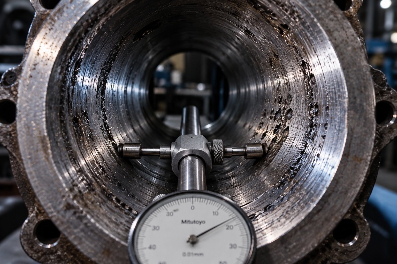
Process symptoms tell you something is wrong. Bore measurements tell you exactly how wrong. You cannot diagnose barrel wear with confidence without physically measuring the inside diameter and comparing it against the nominal specification.
The standard approach uses a dial bore gauge (such as a custom electronic micrometer mounted on a movable sled) or a telescoping gauge paired with an outside micrometer. The barrel must first be thoroughly cleaned — typically with a wire brush and copper or brass gauze — and cooled to room temperature. Measurements are then taken at regular intervals, commonly every one to three inches or in one-L/D increments along the barrel length, and recorded against the original bore dimension.
For context, a new plasticating extruder barrel typically has a bore diameter equal to the nominal size with a tolerance of roughly 0.001 in. oversize. The flight clearance on a new screw is generally the nominal diameter divided by 1000. On a 3.5-in. extruder, for example, that means roughly 0.004 in. of clearance per side when everything is new. Any measurement beyond those factory tolerances represents wear.
Pay special attention to the transition zone — the area where solid polymer melts — because this is where the most wear typically occurs. Abrasive fillers, high solids pressure, and aggressive melting dynamics concentrate forces in this region, often producing a wear pattern that is far worse in the middle of the barrel than at either end.
When Wear Becomes Critical
So how much wear is too much? The answer depends on the demands of your application. Industry guidelines offer several benchmarks for evaluating screw replacement — and because barrel and screw wear are directly linked, the same logic applies to the barrel:
- 4x rule: Many processors consider replacement when the flight clearance reaches four times the original clearance. On that 3.5-in. extruder, this means roughly 0.016 in. per side instead of the original 0.004 in.
- Hard-facing depletion: When the hard facing on screw flights (typically about 0.060 in. thick) is completely worn through, performance drops sharply — and the barrel liner is likely showing comparable degradation.
- Application criticality: High-precision or critical-duty applications, such as medical tubing, may demand replacement after the clearance doubles (2x). Noncritical products like corrugated pipe can tolerate substantially more wear before product quality suffers.
A barrel with an iron-based bimetallic liner will typically outlast three screw service lives, but that does not mean barrel wear should be ignored during screw changes. Every time a screw comes out, the barrel bore should be measured and the readings logged. This practice builds a wear-rate history that lets you predict when replacement will be necessary — rather than discovering it during an unplanned production crisis.
Waiting too long carries real risk. A severely worn extrusion barrel does not just reduce efficiency; it can lead to catastrophic screw-to-barrel contact, metal contamination in your product, or a barrel crack that sidelines the entire line. The economics are straightforward: the cost of a planned replacement is always lower than the cost of emergency downtime combined with reject material and late shipments.
Yet scrap rates and discharge temperatures only reveal that a problem exists. Understanding how barrel wear translates into specific product defects — from dimensional drift to surface imperfections — requires a closer look at what happens to your melt when clearances open up.
How a Worn Barrel Degrades Your Extruded Product Quality
Rising scrap rates and creeping discharge temperatures confirm that something is wrong inside your extruder. But here is the question most processors never ask in enough detail: what exactly is happening to the melt — and the finished product — when that screw and barrel clearance opens up? The answer reaches far beyond a simple drop in throughput. A worn barrel reshapes the physics of melting, mixing, and pressure generation in ways that ripple all the way through to the final product sitting on your customer's dock.
Melt Homogeneity and Mixing Deficiencies
Picture the gap between the extruder screw flight tips and the barrel wall. When everything is new, that clearance is deliberately tight — typically the nominal screw diameter divided by 1000, per side. This narrow gap is what forces polymer forward and generates the shearing action needed for thorough melting and mixing. As the barrel bore wears and that gap widens, an increasing volume of melt leaks backward over the flights instead of advancing toward the die.
This leakage flow does more than reduce output. It fundamentally disrupts the mixing process. In a healthy plasticating unit, polymer is sheared between the flight tip and the barrel wall at precisely controlled intensity. That shear is what disperses colorants evenly, distributes additives throughout the melt, and breaks down any remaining solids into a uniform composition. When the radial clearance doubles or triples, the shear rate in that critical gap drops dramatically. Material passes over the flights without receiving adequate dispersive mixing.
The real-world consequences show up fast. You will notice color streaks or uneven pigment intensity in your extrudate — especially with challenging colorants or masterbatches that demand high shear for proper dispersion. Additive distribution suffers the same way: UV stabilizers, flame retardants, or processing aids that are not uniformly blended into the melt create localized weak spots in the finished product. As extrusion specialists have documented, worn mixing sections and barrier flights lose their ability to produce an isothermal, homogeneous melt — and once that mixing capacity is gone, no amount of downstream adjustment can fully compensate.
For processors running glass-filled or mineral-filled compounds, the problem compounds itself. Abrasive fillers accelerate screw and barrel wear, which in turn reduces the very mixing efficiency needed to distribute those fillers uniformly. The result is a self-reinforcing cycle: poor filler distribution leads to inconsistent mechanical properties in the finished part, while the fillers themselves continue wearing the equipment faster.
Dimensional Variation and Surface Defects
Consistent melt pressure at the die is the foundation of dimensional accuracy in any extruded product — pipe, profile, sheet, or film. A worn barrel undermines that foundation directly. As increased flight clearance allows melt to leak backward, the extruder screws lose their ability to develop stable, uniform pumping pressure. The pressure at the die fluctuates, sometimes subtly, sometimes severely enough to cause visible surging.
Imagine running a pipe extrusion line where the melt pressure at the die head swings by even a few percent. That variation translates into wall thickness inconsistency along the length of the pipe. In blown film, the same pressure instability produces gauge variation — thicker and thinner bands that compromise both performance and appearance. Profile extrusions lose their dimensional precision, leading to parts that no longer fit within tolerance or fail to assemble properly with mating components.
Surface quality takes a parallel hit. When the melt leaving the die is not thermally and compositionally uniform, surface defects emerge. Shark skin — that characteristic rough, matte texture on the extrudate surface — becomes more prevalent when melt temperature and viscosity vary across the flow channel. Melt fracture, a more severe distortion of the extrudate surface, can appear when pressure instability pushes shear stress at the die wall beyond critical thresholds. These are not cosmetic nuisances; in applications like medical tubing or food packaging film, surface defects mean rejected product.
The connection between barrel bore condition and these downstream defects is often overlooked because so many other variables — die condition, cooling rates, haul-off speed — also influence dimensional and surface quality. But when operators have ruled out those factors and dimensional scatter persists, the extruder screw and barrel clearance is almost always the root cause hiding in plain sight.
The Hidden Cost of Running a Worn Barrel
Here is where barrel wear becomes genuinely expensive — not in dramatic equipment failures, but in the quiet, daily compromises operators make to keep product within spec. A worn barrel forces a cascade of process adjustments that each carry their own cost penalty:
Operators raise barrel zone temperatures to compensate for reduced heat-transfer efficiency at the worn barrel wall. They slow line speed to bring discharge temperatures back into range — a move that, as research on a 100-mm extruder demonstrated, can reduce throughput by 13% or more. Quality teams tighten downstream inspection tolerances and increase sampling frequency. Downstream equipment — cooling baths, calibrators, pullers — gets adjusted to accommodate wider variation in the extrudate coming off the die.
Every one of these compensations costs money. Higher barrel temperatures consume more energy. Reduced line speeds mean fewer pounds of product per hour from the same fixed asset. Tighter inspection catches more rejects, but the rejected material still consumed energy and machine time. And the cumulative effect on product properties is not always visible at the extruder — it shows up later, in field failures, customer complaints, or warranty claims.
The key quality metrics affected by a deteriorating barrel include:
- Melt temperature uniformity — wider thermal variation across the melt stream degrades processing consistency
- Dimensional tolerance — pressure instability causes wall thickness, profile dimensions, and gauge to drift outside specification
- Surface finish — poor melt homogeneity and pressure fluctuations promote shark skin, melt fracture, and other surface defects
- Color consistency — reduced dispersive mixing leads to streaks, uneven pigment distribution, and batch-to-batch variation
- Mechanical properties — non-uniform filler distribution and thermal degradation from excessive melt temperatures weaken the finished product
A processor running a single extruder line 24 hours a day can easily accumulate tens of thousands of dollars in hidden costs from a worn barrel before anyone connects the dots between scrap rates, energy bills, and bore measurements. That is why understanding the quality impact is not academic — it is the business case for timely plastic extruder barrel replacement.
Of course, the right replacement strategy depends heavily on the type of extruder you are running. The bore geometry, barrel construction, and wear patterns differ significantly between single-screw and twin-screw configurations — and those differences shape every decision from specification through sourcing.
Replacement Differences Across Single and Twin Screw Extruder Types
A barrel is not just a barrel. The extruder type sitting on your plant floor dictates the bore geometry, construction method, and manufacturing tolerances of the replacement you need to order. Treating all barrel replacements the same way — regardless of whether you are running a single screw extruder, a parallel twin, or a conical twin — is a reliable recipe for procurement delays, fitment problems, and shortened service life on the new component.
Each configuration brings its own set of challenges. Understanding them before you pick up the phone to request a quote saves weeks of back-and-forth and ensures the replacement barrel performs from the first production run.
Single Screw Extruder Barrel Replacement Considerations
The single screw extruder barrel is the most straightforward replacement scenario you will encounter. The bore is a single cylindrical hole — one continuous round cross-section from feed throat to discharge flange. Standard flange bolt patterns connect the barrel to the gearbox housing at one end and to the die adapter at the other. If you have ever replaced a hydraulic cylinder, the dimensional logic is similar: measure the bore, match the length, confirm the flange geometry, and verify the feed opening.
Straightforward does not mean simple, though. The most critical specification to match is the L/D ratio — the barrel's working length divided by its bore diameter. An extruder originally built with a 24:1 L/D barrel processes material very differently from one designed for 30:1 or 36:1. A longer barrel provides more residence time, more melting capacity, and more mixing — but it also changes pressure profiles and shear history. Swapping in a barrel with a different L/D ratio without adjusting the screw design can create feed instability, incomplete melting, or excessive melt temperature. Always match the replacement to the original specification unless you are intentionally redesigning the process with a new screw to match.
Single-screw barrels account for the majority of replacement orders across the industry. Their one-piece monolithic construction, standardized flange dimensions, and round bore make them the easiest to specify, source, and install — which is exactly why a sloppy approach to measurement still leads to problems. The tolerances are forgiving compared to twin-screw configurations, but "forgiving" does not mean "optional."
Parallel and Conical Twin Screw Barrel Differences
Step into twin-screw territory and the complexity multiplies. Every twin screw barrel features a figure-eight bore — two overlapping cylindrical channels fused together to create the intermesh zone where screws interlock. This geometry demands significantly tighter manufacturing tolerances than a round single-screw bore. Typical flight-to-barrel clearances on a new twin screw and barrel system fall in the range of 0.15 mm to 0.30 mm, and even small deviations in that clearance compromise the melt seal that drives positive displacement and self-wiping action.
Parallel co-rotating twin-screw extruders add another layer of complexity: modular barrel construction. Rather than a single monolithic tube, these machines use individual barrel segments — each typically 4 to 5 L/D in length — bolted together end to end. Each segment can serve a different process function: closed conveying, side feeding, venting, or injection. Replacing a worn barrel on a segmented system might mean swapping just one or two segments rather than the entire barrel, but each segment must maintain identical bore diameter and alignment to its neighbors. A bore mismatch of even a fraction of a millimeter at a segment joint creates a step that catches material, generates localized wear, and accelerates degradation of the adjacent segments.
Conical twin-screw configurations introduce yet another variable: a tapered bore. The figure-eight profile gradually shrinks from a larger diameter at the feed end to a smaller diameter at the discharge. This taper builds compression directly into the barrel geometry, making conical designs well suited for gentle processing of heat-sensitive materials like PVC. The trade-off is that conical barrels are inherently monolithic — you cannot add or remove segments to adjust L/D ratio — and the tapered bore requires precision machining along a converging axis. Sourcing a replacement means finding a manufacturer capable of producing that exact taper angle, which narrows the supplier field considerably compared to standard parallel or single-screw barrels.
| Extruder Type | Bore Geometry | Typical Barrel Construction | Key Replacement Challenges |
|---|---|---|---|
| Single Screw | Single cylindrical bore | Monolithic (one-piece) | Matching L/D ratio; verifying feed throat and flange dimensions; confirming heater zone layout |
| Parallel Twin Screw | Constant-diameter figure-eight bore | Segmented (bolted modular sections) | Tight bore tolerances at segment joints; matching segment sequence and port locations; maintaining alignment across multiple segments |
| Conical Twin Screw | Tapered figure-eight bore | Monolithic (one-piece) | Precise taper angle replication; limited supplier availability; no flexibility to adjust L/D ratio; higher manufacturing complexity |
How Screw Geometry Relates to Barrel Wear Patterns
Here is something that catches many maintenance teams off guard: the screw design already installed in your extruder determines where the barrel wears most — and that wear pattern must inform the replacement barrel specification.
L/D ratio sets the stage, but compression ratio and flight depth drive the action. A screw with a high compression ratio forces a large volume of solid polymer into a progressively smaller channel, generating intense pressure in the transition zone. That pressure pushes screw flights hard against the barrel wall, concentrating abrasive wear in a band that often corresponds to roughly the middle third of the barrel length. It is the same region where bore measurements consistently show the worst degradation, as discussed in the diagnostic section above.
Flight depth matters, too. Deep-flighted feed sections move high volumes of unmelted pellets and granules that have not yet softened enough to flow smoothly. Abrasive fillers — glass fiber, calcium carbonate, mineral additives — are at their most aggressive in this zone because they are still in solid form, scraping directly against the bore surface under high bulk pressure. Research on counter-rotating twin-screw extruders has shown that large separating forces develop in the calender gap, physically deflecting the screws toward the barrel wall and concentrating wear at predictable angular positions — typically between 30 and 60 degrees from vertical. In those machines, the barrel does not wear in a uniform ring; it wears in a crescent pattern that conventional bore diameter measurements can miss if taken at only one angular position.
The practical takeaway is this: when specifying a replacement barrel, you are not just ordering a tube with the right dimensions. You are ordering a component whose liner material, bore tolerance, and thermal design must account for the specific screw geometry and wear pattern unique to your process. A replacement barrel paired with a high-compression screw processing glass-filled nylon needs a very different liner grade and hardness profile than one paired with a low-compression barrier screw running unfilled polyethylene — even if the bore diameter and length are identical.
That connection between barrel metallurgy and your specific resin and filler combination is exactly where the next critical decision lies: choosing the right barrel material to survive the demands of your process rather than simply matching a dimension on a drawing.
Choosing the Right Barrel Material for Your Resin and Process
Matching bore dimensions and flange patterns gets a replacement barrel onto your extruder. Matching the material to your resin and filler combination determines how long it stays there. Too many processors default to whatever their original barrel was made of — or worse, choose solely on purchase price — without evaluating whether their production reality has changed since the last barrel was installed. Different resins, higher filler loadings, or increased run hours all shift the equation. Getting the metallurgy right is the difference between a barrel that delivers years of reliable service and one that starts wearing out within months.
Standard Nitrided Steel Barrels
If you are processing clean, unfilled commodity resins like PE, PP, PS, or ABS, a nitrided steel barrel is often all you need. The most common substrate is 38CrMoAlA nitriding steel, a chromium-molybdenum-aluminum alloy specifically formulated to respond well to the gas nitriding process.
During gas nitriding, the barrel is held in a nitrogen-rich atmosphere at elevated temperature for an extended cycle — typically 24 to 72 hours. Nitrogen atoms diffuse into the steel surface and form hard iron-aluminum nitride compounds, creating a wear-resistant case layer without the distortion risks of through-hardening. The result is a surface hardness typically reaching HV 900 to 1100 (roughly Rockwell C 65-70 equivalent at the surface) while the core remains tough and ductile.
The appeal is straightforward: nitrided extrusion barrels are cost-effective, widely available, and perfectly adequate for non-abrasive, non-corrosive applications. The limitation is equally straightforward. That nitrided case layer has a finite effective depth. When processing materials with even moderate filler content — say 10-15% calcium carbonate or talc — the case can wear through relatively quickly under continuous production conditions, exposing the softer base metal underneath and accelerating bore degradation. For processors running glass-fiber-reinforced compounds or corrosive resins like PVC, a nitrided barrel is simply the wrong tool for the job.
Bimetallic Barrel Linings for Demanding Applications
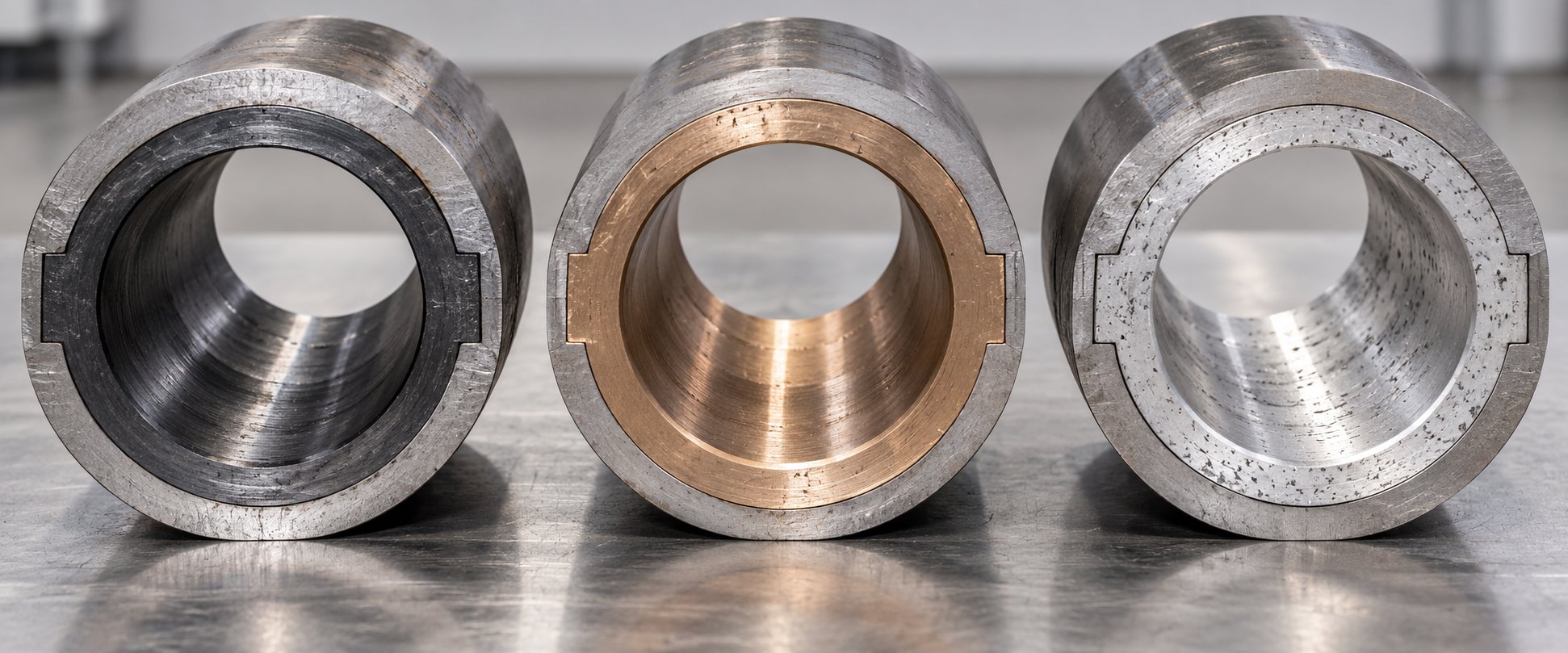
When your process involves abrasive fillers, corrosive polymers, or high-volume continuous operation, bimetallic construction is the industry standard upgrade. A bimetallic barrel pairs a high-strength carbon or alloy steel outer shell with a centrifugally cast alloy liner on the bore surface. During manufacturing, molten alloy is poured into the rotating barrel shell. Centrifugal force distributes the alloy evenly and produces a dense, metallurgically bonded lining — typically 1.5 to 3 mm thick — with minimal porosity and strong adhesion to the base metal.
Here is where material selection gets strategic, because not all bimetallic liners are the same. The two primary categories serve very different purposes:
- Abrasion-resistant linings — Designed for glass-filled, mineral-filled, and recycled compounds containing contaminants. A common formulation uses a nickel-boron-based iron alloy with a martensitic structure, delivering hardness in the range of Rockwell C 58-65 and a service life at least four times that of nitrided barrels. For extreme abrasion, tungsten-carbide-rich alloys push macro hardness to Rc 62-68, with micro hardness of the carbide particles exceeding DPH 4000. These super-wear linings are the go-to choice when extruder screws and barrels face continuous exposure to highly filled engineering plastics.
- Corrosion-resistant linings — Engineered for PVC, fluoropolymers, flame-retardant compounds, and other resins that release hydrochloric or hydrofluoric acids during processing. These liners typically use cobalt-nickel-based alloys with high chromium and boron content, offering over 10 times the service life of nitrided barrels in severely corrosive atmospheres, with hardness around Rc 50-55.
Choosing between abrasion and corrosion resistance — or specifying a liner that balances both — depends entirely on what you are running. A processor extruding glass-filled nylon needs the tungsten-carbide abrasion protection. A PVC pipe producer needs the corrosion-resistant alloy. A custom compounder switching between multiple materials may benefit from a dual-purpose liner that provides moderate protection against both wear mechanisms. The resin dictates the metallurgy — not the other way around.
Advanced and Specialty Barrel Materials
Some applications push even bimetallic linings to their limits. That is where powder metallurgic (PM) tool steels enter the picture. Materials like CPM 10V — a Crucible Industries product containing 9.75% vanadium — use the particle metallurgy process to achieve an extremely high volume of hard vanadium carbides distributed uniformly throughout the steel. The result is abrasion resistance that exceeds conventional tool steels by a wide margin, making CPM 10V a proven choice for injection molding screws and barrels processing continuous glass, mineral, ceramic, and metal-filled plastics.
For even more demanding situations, CPM 15V raises the vanadium carbide content to 14.5%, providing a further step up in wear resistance. And when both corrosion and abrasion must be addressed simultaneously, stainless PM grades like CPM 420V and CPM S90V combine high vanadium carbide content with sufficient free chromium to resist chemical attack — a combination that conventional alloying methods cannot achieve.
The trade-off is cost. PM tool steel barrels carry a significantly higher price tag than bimetallic options. Is that premium justified? It depends on three factors: how abrasive your resin and filler combination is, how many production hours per year the extruder runs, and your total cost of ownership calculation. A barrel that costs twice as much but lasts three times as long while reducing downtime and scrap is not expensive — it is the cheapest option you have. Conversely, specifying CPM 10V for a line running unfilled HDPE is spending money that delivers no return.
| Material Type | Best Suited For | Relative Cost | Expected Service Life vs. Nitrided |
|---|---|---|---|
| Nitrided Steel (38CrMoAlA) | Unfilled commodity resins (PE, PP, PS, ABS); low to moderate production volume | Low | 1x (baseline) |
| Bimetallic — Abrasion Resistant (Nickel-Boron) | Glass-filled, mineral-filled, and recycled compounds with abrasive contaminants | Medium | 4x or more |
| Bimetallic — Super Wear (Tungsten Carbide) | Extreme abrasion: high glass-fiber content, ceramic-filled, or metal-filled resins | Medium-High | 5x or more |
| Bimetallic — Corrosion Resistant (Cobalt-Nickel) | PVC, fluoropolymers, flame-retardant compounds releasing corrosive acids | Medium | 10x in corrosive environments |
| PM Tool Steel (CPM 10V / 15V) | Continuous processing of highly abrasive filled engineering plastics at high volume | High | Significantly exceeds bimetallic in extreme abrasion |
| PM Stainless Steel (CPM 420V / S90V) | Combined severe abrasion and corrosion; multi-material custom processing | High | Exceptional in dual-threat environments |
Selecting the right liner or barrel material is ultimately a conversation between your process data and your production economics. Know your resin. Know your fillers. Know your annual run hours. Those three inputs, more than anything else, point you toward the material that delivers the lowest cost per pound of quality product over the barrel's service life.
Material selection locks in the performance potential of your new barrel — but that potential is only realized if the replacement is specified with exact dimensional accuracy. And getting those dimensions right requires more than pulling up an old purchase order; it means physically measuring the barrel you are replacing and documenting every critical feature that the new one must replicate.
How to Measure and Specify a Replacement Extruder Barrel
You have identified the wear, chosen the right liner material for your resin, and decided it is time to order a replacement. Here is where many procurement efforts stall — or worse, result in a barrel that does not fit. Pulling up the original purchase order or referencing a decades-old OEM drawing sounds like the logical starting point, but it often leads you astray. Barrels get modified over their service life. Feed throats are reworked. Thermocouple wells are relocated. Heater zone layouts are reconfigured. If your barrel extruder has been in service for ten or fifteen years, the machine on your floor may not match the machine that left the factory.
The only reliable path to a correct replacement is measuring the barrel you are removing and documenting every critical feature yourself. Skip this step, and you risk lead-time delays, costly rework, or a barrel that cannot maintain proper temperature control once installed.
Critical Dimensions You Must Measure
Think of barrel specification as building a complete dimensional profile — not just capturing a bore size and a length. Every measurement feeds into the manufacturer's ability to replicate the barrel accurately. Miss one, and you will be fielding phone calls and emails to fill in the gaps, adding days or weeks to your lead time.
Follow this sequence to capture everything a barrel manufacturer needs:
- Bore diameter (nominal and actual) — Record the nominal bore diameter from your equipment records, then measure the actual bore using a dial bore gauge or electronic micrometer on a movable sled. Take readings at one-L/D increments along the full barrel length with the barrel clean and at room temperature. The nominal value tells the manufacturer what you need; the actual measurements tell both of you how far the old barrel has deviated — and confirm that you are not accidentally replicating an already out-of-spec dimension.
- Overall barrel length — Measure the total length from the rearmost face (gearbox-side flange) to the foremost face (die-side flange or adapter seat). Use a long tape measure or a laser distance tool for barrels over six feet. Do not rely on the screw length as a proxy — many screws extend beyond the barrel at the feed end.
- Flange-to-flange length — This is the distance between the sealing faces of the barrel flanges. It determines how the barrel sits in the extruder frame and aligns with both the gearbox and the die adapter. Even a quarter-inch discrepancy can prevent proper bolt-up or cause alignment issues with the plastic extruder screw.
- Feed throat opening dimensions — Measure the length, width, and shape of the feed opening. Feed throats are not all identical — some are round, some are rectangular, and some include offset geometry designed for specific feeding characteristics. Record the position of the opening relative to the rear flange face.
- Flange bolt pattern — Count the bolts, measure the bolt circle diameter, and note the bolt size and thread pitch. Sketch or photograph both the gearbox-end and die-end flanges. Flange patterns can differ from end to end, and aftermarket modifications — such as added dowel pin holes for alignment — must be captured.
- Outside diameter and any mounting features — Record the barrel OD, the location of any support saddle grooves or clamp points, and the position of mounting brackets. These features determine how the barrel is supported in the frame, and a mismatch can cause alignment problems during installation.
A set of clear photographs taken during disassembly — with a scale reference visible — is one of the cheapest insurance policies in this entire process. Photograph both flanges, the feed throat, every port and connection point, and any markings or serial numbers stamped on the barrel surface.
Heater Zone Layout and Thermocouple Positions
A replacement barrel that matches bore diameter and length perfectly can still cause serious problems if the heater zone layout does not align with your control system. Every extruder control panel is wired to a specific number of zones, and each zone expects its heater band and thermocouple at a defined position along the barrel length. A mismatch means your temperature controller is reading one zone while heating another — or leaving a section of barrel with no active temperature regulation at all.
Document the following for each zone:
- Heater band location and width — Measure the axial position (distance from the rear flange) and the width of each heater band. Record whether bands are clamped, bolted, or cast-in-place.
- Thermocouple well location and depth — Mark the exact axial and radial position of every thermocouple well. Best practice for thermocouple placement, as extrusion control specialists recommend, calls for penetration approximately 60-70% of the way through the barrel wall to get a reading closer to actual melt temperature rather than the outer surface. If your existing wells are shallower than this, the replacement barrel offers an opportunity to correct that — but the control system must be adjusted accordingly.
- Cooling channel configuration — Many barrels incorporate air-cooling blowers or drilled cooling passages between zones. Record the location, size, and type of cooling provisions. Some designs use finned barrel sections for air cooling; others route water or oil through drilled channels. The replacement must replicate this layout or your ability to pull heat out of overdriven zones disappears.
Pay particular attention to thermocouple positioning relative to heater bands. Placing a thermocouple directly beneath a heater — rather than between heaters — produces false high readings that trick the controller into underheating the zone. This is a common error on replacement barrels when thermocouple wells are drilled without referencing the actual heater band positions on the machine.
Documenting Feed Barrel and Vent Port Specifications
The extruder feed barrel section is not just a pipe with a hole in the top. It is often the most feature-rich portion of the entire barrel, and failing to capture its unique characteristics is one of the most frequent specification errors.
Many feed sections incorporate independent water-cooling channels designed to keep the feed throat temperature low enough to prevent premature pellet melting and bridging. These channels must be replicated precisely — their diameter, routing, and connection fittings all affect cooling performance. Some extruders use grooved feed barrels — featuring axial or helical grooves machined into a water-cooled separate feed zone — specifically designed to improve intake of slippery, hard resins like HDPE. If your machine has a grooved feed section, the replacement must match the groove geometry, depth, pitch, and length exactly. Grooved and smooth feed zones produce fundamentally different feeding behavior, and substituting one for the other changes the entire process.
For vented barrel designs, the vent port demands equal attention. A vented extruder positions its vent opening at approximately 70% of the barrel's total length, and the screw design ahead of the vent must fully melt and decompress the polymer before the material reaches that point. Record the vent port's axial position, its width and length, its angular orientation on the barrel, and the flange or connection detail used to attach vacuum equipment or stuffing hardware. If your vent port has been modified — enlarged, relocated, or fitted with a custom adapter — document the current configuration, not what the original drawing shows.
Accurate documentation of your existing barrel is the single most important step in ensuring a correct replacement fit. Measure the machine on your floor — not the drawing in your file cabinet.
With every dimension, zone layout, port position, and feed section feature documented, you have the specification package a manufacturer needs to produce a barrel that drops into your extruder without modification. That specification in hand, the next decision becomes strategic rather than technical: should you invest in a brand-new replacement barrel, reline the existing one, or repair localized damage — and which option delivers the best return for your specific situation?
New Barrel vs Repair vs Reline: A Decision Framework
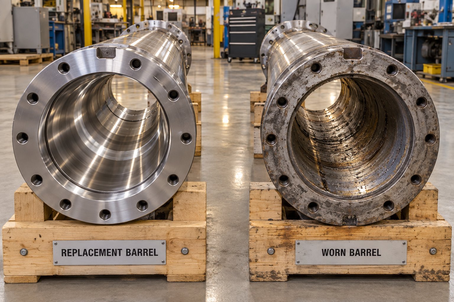
A detailed dimensional specification tells you exactly what barrel to order. It does not tell you whether ordering a brand-new barrel is actually the smartest move. In many situations, relining the existing barrel or repairing localized damage delivers the same performance at a fraction of the cost and lead time. The challenge is knowing which path fits your specific situation — because the wrong call either wastes money on a premature replacement or sinks budget into a repair that fails within months.
When a New Replacement Barrel Is the Right Choice
A new barrel makes clear sense under several conditions. If bore measurements show severe, uniform wear across the full length — particularly when the bimetallic liner has been consumed past the point where relining is structurally viable — restoration simply has nothing left to work with. As industry analysis from BLOOM Engineering notes, the finished bimetallic liner is typically only about 1.5 mm thick, meaning deep or through-liner wear leaves no margin for re-machining.
Replacement is also the right call when the barrel's base metallurgy needs an upgrade. Imagine you purchased a Davis-Standard extruder years ago with a standard nitrided barrel, and your production has since shifted to 30% glass-filled nylon. Relining the old barrel with the same liner chemistry that already failed repeats the problem. A new barrel with a tungsten-carbide bimetallic lining addresses the root cause rather than just the symptom.
Production urgency plays a role, too. If your Davis-Standard extruder is sitting idle and every day of downtime costs thousands in lost revenue, sourcing a new barrel can sometimes beat repair turnaround — especially when you work with factory-direct manufacturers like NANHAIYA, who supply custom and replacement screw barrels for extrusion and injection molding applications. Factory-direct sourcing often reduces both lead time and cost compared to routing orders through equipment OEM channels, giving maintenance teams an alternative when a davis standard extruder for sale through the original builder carries a premium price tag and a longer wait.
Re-Lining and Repair as Cost-Effective Alternatives
Not every worn barrel belongs in the scrap pile. Re-lining — boring out the worn bore and installing a new centrifugally cast bimetallic sleeve — essentially gives the barrel a brand-new working surface at a lower cost than full replacement. The process requires boring the inner wall to approximately 1.0 inch larger than the original bore diameter to seat the new liner, so the barrel must retain sufficient wall thickness to absorb that material removal and still contain operating pressure safely. As NANHAIYA's technical team explains, re-lining can save 25% to 50% compared to new barrel pricing, with injection molding barrels offering the widest savings margin due to their higher replacement cost.
For standard extrusion barrels, the economics are tighter. New extrusion barrels are relatively affordable compared to injection molding barrels, which narrows the repair margin. A full-length reline can approach new-barrel cost once you factor in the machining, liner manufacturing, and heat-shrink installation steps involved.
Localized repair fills a different niche. When damage is confined to a single zone — heavy scoring in the feed section from contaminated regrind, or corrosive pitting in the metering zone from PVC off-gassing — techniques like alloy spray welding or weld overlay can restore just the damaged region. A "short sleeve" repair addresses only the worn section, leaving healthy bore untouched and preserving maximum wall thickness. This targeted approach delivers the fastest turnaround and lowest cost of any restoration method, provided the wear pattern genuinely is localized rather than widespread.
Decision Framework for Replace vs Repair
Gut instinct is a poor guide for a decision that can swing tens of thousands of dollars in either direction. The following framework evaluates the same variables every time, pointing clearly toward the option that fits your barrel's actual condition and your production reality:
| Decision Criteria | Favors New Replacement | Favors Re-Lining | Favors Localized Repair |
|---|---|---|---|
| Extent of Wear | Severe, uniform wear across full length; liner worn through to backing steel | Moderate-to-heavy wear distributed across most of the barrel; liner still has backing integrity | Damage confined to one or two zones with the remainder within tolerance |
| Barrel Age and Repair History | Previously relined or repaired; cumulative material removal limits further restoration | First repair cycle; barrel body is structurally sound with adequate wall thickness | Barrel is relatively young with no prior repairs and isolated damage |
| Material Upgrade Needed | Current liner chemistry is inadequate for the resin being processed (e.g., switching to abrasive filled compounds) | Upgraded liner alloy can be specified during the reline process | Existing liner chemistry is appropriate; only the damaged zone needs restoration |
| Budget Constraints | Full capital budget available; total cost of ownership justifies the investment | Budget is limited but sufficient for a repair that approaches 50-70% of new barrel cost | Minimal budget; repair cost stays well below 50% of replacement price |
| Downtime Tolerance | Spare barrel available or production schedule allows planned shutdown; factory-direct sourcing can compress lead times | Moderate lead time acceptable; reline turnaround is typically shorter than new barrel manufacturing for complex configurations | Minimal downtime available; localized repair offers the fastest turnaround — often days to a few weeks |
| Future Production Plans | Resin portfolio is changing; higher throughput targets or tighter quality specs are planned | Current process and resin mix will remain stable; restoring original capability is sufficient | No process changes anticipated; extending current barrel life is the priority |
Notice the pattern: as wear severity, barrel age, and process demands increase, the decision shifts from repair toward replacement. A barrel with isolated feed-section scoring and years of remaining wall thickness sits firmly in the localized repair column. One with moderate full-length wear on its first repair cycle is a strong reline candidate. And a barrel that has already been relined once, is now processing a more abrasive compound than it was designed for, and shows uniform degradation across every zone belongs in the replacement column — where the investment buys not just a new bore surface but a metallurgical upgrade matched to the actual demands of the process.
The key principle in every case: decide based on measured bore data, documented wear patterns, and honest economics — not on which option a vendor happens to sell. A structured framework makes the decision repeatable and defensible, whether you are presenting it to a plant manager or documenting the rationale in your maintenance records.
Whichever path the data points toward, the physical work of removing the old barrel and installing the new or restored one follows a specific sequence — and the quality of that installation determines whether your investment performs as expected from day one.
Step-by-Step Extruder Barrel Replacement Procedure
A new barrel sitting on the shop floor is just an expensive tube until it is installed correctly. The physical replacement process involves heavy components, high-temperature systems, precise alignment tolerances, and dozens of electrical and fluid connections that must be restored in the right sequence. Rushing through installation — or improvising without a plan — can damage the new barrel before it ever processes a single pellet. Every step below exists because someone, somewhere, learned the hard way what happens when it gets skipped.
Pre-Replacement Preparation and Safety
Before you touch a wrench, the extruder must be fully isolated and the barrel cleared of residual material. This phase sets the foundation for a safe, efficient swap and prevents the kind of surprises that turn a planned two-day shutdown into a week-long ordeal.
Start with a complete lockout/tagout of all energy sources — electrical power to the drive motor and heater circuits, hydraulic or pneumatic systems, and any automated feed equipment. Verify zero-energy state at every isolation point. Then purge the barrel of remaining resin by running the extrusion screw at low RPM with the hopper slide gate closed until output ceases. For thermally sensitive materials, follow with a commercial purge compound to displace degraded polymer clinging to barrel walls and screw channels.
With the barrel purged, allow temperatures to drop to a safe handling range — but do not let the barrel cool completely before removing the screw. A hot barrel has an expanded bore that makes screw extraction far easier than trying to pull a cold screw from a cold bore. Disconnect heater band power leads, thermocouple wires, and cooling lines zone by zone, labeling every connection as you go. Photograph each wiring group, coolant fitting, and sensor location — these images become your reassembly blueprint and eliminate guesswork when reconnecting the new barrel.
Barrel Removal and New Barrel Installation
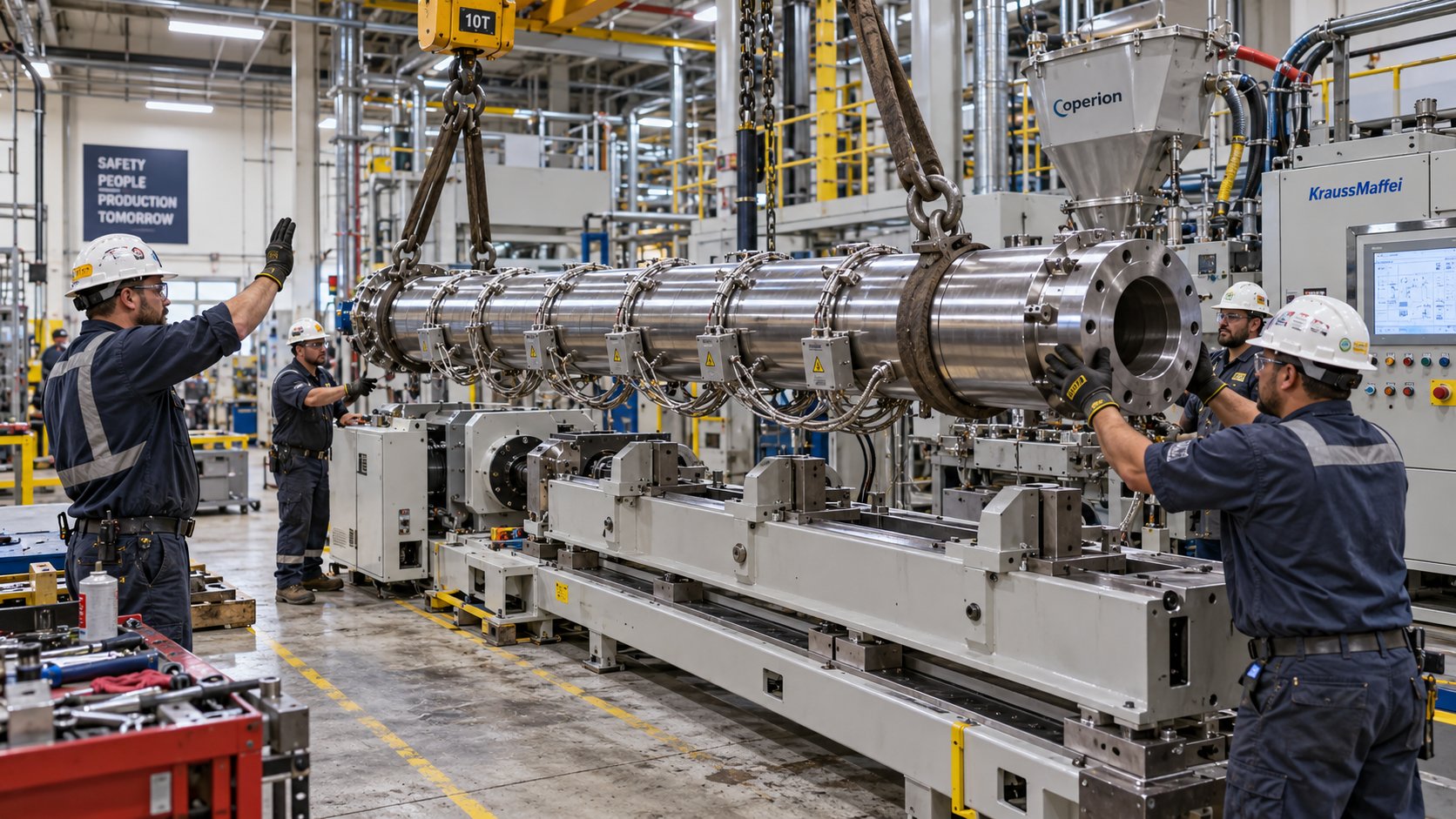
Removing the old barrel and setting the new one in place is the most physically demanding phase. Even modestly sized screw extruders have barrels weighing several hundred pounds, and larger machines can have barrels well over a ton. Rigging must be planned, not improvised.
Use a hydraulic push-jack or threaded pusher to advance the screw out of the barrel once the die head and connecting piping have been removed. As experienced maintenance teams recommend, push the screw out in increments of three to four diameters at a time, cleaning each exposed section before continuing. Never use brute force — a screw that resists extraction may have a burr, an oversized flight, or a drive-spline interference that force alone will worsen into permanent damage.
With the screw extracted, unbolt the barrel flange connections at the gearbox end and the discharge end. Support the barrel's full weight with an overhead crane or chain hoist before removing the final bolts, then carefully withdraw the barrel from the frame and barrel supports.
Positioning the new barrel reverses this sequence — but with one critical addition: alignment verification. The barrel bore must be aligned to the gearbox drive quill centerline, not simply leveled. Davis-Standard's alignment protocol uses an optical or laser alignment scope inserted into the drive quill, rotating it to establish a fixed centerline. The barrel and feed throat are then adjusted via barrel supports until the bore axis matches that reference line precisely. Leveling alone is unreliable because it only measures the vertical plane and tells you nothing about the actual drive quill orientation.
Once aligned, torque flange bolts to the values specified in your equipment manufacturer's documentation, following a star or crisscross pattern to distribute clamping force evenly. Verify barrel straightness by checking for deflection at the discharge end using dial indicators positioned at 90-degree intervals.
Improper barrel alignment is the leading cause of premature wear on newly installed barrels and screws. Always align to the gearbox drive quill centerline — never rely on leveling alone.
Pay close attention to the barrel support system as well. Supports must allow the barrel to expand freely as it heats without introducing lateral forces that bend the bore. Steel expands at approximately 0.000006 in. per inch per degree Fahrenheit — a 4.5-inch, 36:1 barrel operating at 450 °F grows roughly 0.320 inches longer than its cold length. If the supports lock the barrel in place or bind due to corrosion, that thermal growth has nowhere to go except into a bend. Brass-contact joints and sliding saddle designs prevent this binding and maintain the alignment you just verified.
Before installing the extrusion screw into the new barrel, follow the golden rule: insert a cold (room temperature) screw into a cold barrel on the very first fit. At room temperature, the bore is at its smallest diameter. If the screw slides in smoothly, you have confirmed that there are no oversized flights, shaft bends, or drive-spline interferences. As thermal expansion data illustrates, a 2.5-inch barrel at 250 °C expands its bore by roughly 0.006 inches — enough to mask a defective screw that will seize once temperatures equalize. Only after this cold fit-check passes should you proceed with all subsequent installations using a cold screw into a hot barrel.
Reconnecting Heating, Cooling, and Control Systems
With the barrel bolted in place, aligned, and the screw confirmed to fit, the final phase restores the thermal control infrastructure that governs your process. Sloppy reconnection here undermines everything the alignment and specification work accomplished.
Install heater bands on the clean barrel surface with full metal-to-metal contact — no air gaps, no polymer residue trapped underneath. As extrusion maintenance engineers emphasize, tighten clamping bolts in a crisscross pattern to the manufacturer's specified torque. Uneven clamping warps the heater shell, creates internal hot spots, and accelerates element failure. Use new terminal hardware rather than reusing heat-cycled lug nuts whose threads may have work-hardened and lost reliable contact.
Reconnect thermocouple wires to their correct zones using the labeled photographs taken during disassembly. A thermocouple plugged into the wrong zone means the PID controller reads one barrel section while commanding heat to another — a recipe for overheating, cold spots, or both. Verify that each thermocouple is seated at the proper depth in its well: spring-loaded fittings should compress by the specified amount so the sensor tip contacts the well bottom rather than floating in an air gap.
Reattach all cooling lines — water, oil, or air — and pressure-test connections for leaks before energizing anything. A coolant leak onto a hot barrel creates steam hazards and can damage heater band insulation.
The complete procedure, consolidated into a sequential checklist, ensures nothing gets missed under the time pressure of a shutdown:
- Lock out and tag out all energy sources — electrical, hydraulic, pneumatic, and automated feed systems.
- Purge the barrel by running the screw at low RPM with the hopper closed until output stops; follow with purge compound if required by the resin.
- Disconnect heater bands, thermocouples, and cooling lines zone by zone, labeling and photographing every connection.
- Remove the die head and discharge piping while the barrel is still warm.
- Extract the screw using a hydraulic push-jack, advancing in three-to-four-diameter increments and cleaning each exposed section with brass tools and copper gauze.
- Support the barrel weight with an overhead crane or hoist, unbolt flanges, and withdraw the old barrel from the frame.
- Inspect and clean the gearbox drive quill, feed throat mating surface, and barrel support saddles before positioning the new barrel.
- Position the new barrel onto supports and loosely attach flange bolts.
- Align the barrel bore to the drive quill centerline using an optical or laser alignment scope; adjust barrel supports until alignment is confirmed.
- Torque flange bolts to manufacturer-specified values in a star pattern; verify straightness with dial indicators at the discharge flange.
- Perform a cold screw fit-check — insert the room-temperature injection screw or extrusion screw into the room-temperature barrel to confirm smooth, unobstructed passage.
- Install heater bands on clean barrel surfaces, tightening clamps in a crisscross pattern to specified torque with new terminal hardware.
- Reconnect thermocouples to the correct zones, verifying seating depth and spring compression at each well.
- Reattach cooling lines and pressure-test all connections for leaks.
- Verify all wiring and connections against disassembly photographs before restoring power.
- Energize heater circuits and confirm that each zone reaches setpoint independently with stable PID response before introducing material.
Skipping any single step — particularly the alignment verification and cold fit-check — creates problems that may not surface for weeks or months but will inevitably manifest as accelerated wear, uneven temperature profiles, or premature screw failure. A methodical installation protects the investment you made in specifying and sourcing the right barrel.
The barrel is bolted in, wired up, and aligned. The temptation is to start running production immediately. Resist it. A new barrel demands a controlled break-in period and a structured validation sequence to confirm that everything performs as expected — and to establish the baseline measurements that will guide your maintenance decisions for years to come.
Post-Installation Validation and Extending Your New Barrel Life
A freshly installed barrel and a perfectly aligned bore do not guarantee results. What happens during the first few hours of operation — and the maintenance habits you build in the months that follow — determines whether that new barrel delivers its full service life or starts degrading far sooner than it should. This final phase is where disciplined teams separate themselves from reactive ones.
Break-In Protocol and Initial Run Validation
You would not take a rebuilt engine straight to redline. The same logic applies here. A new barrel surface — whether bimetallic liner, nitrided bore, or alloy spray coating — benefits from a controlled initial loading sequence that allows the coating to stabilize thermally and establish a proper melt film before full production demands hit.
Follow this break-in sequence:
- Heat soak without material — Bring the barrel up to operating temperature gradually, following the OEM-recommended ramp rate. As Davis-Standard advises, the polymer must be completely molten before any material is introduced, and larger extrusion systems require longer soak times to reach uniform temperature throughout the barrel wall. This soak lets the coating and substrate expand together, relieving residual stress before mechanical load is applied.
- Slow-speed startup with unfilled resin — Introduce a clean, unfilled base resin at low screw RPM. The goal is to develop a stable melt film across the entire bore before subjecting the surface to abrasive fillers. Maintain low speed for 15 to 30 minutes while monitoring motor amperage and melt temperature for stability.
- Gradual ramp to production speed — Increase screw speed in 20-25% increments, holding at each level for several minutes. If your production resin is filled or reinforced, transition from the unfilled break-in material to the production compound during this ramp — not before. Watch melt pressure and motor load closely. Any sudden spike suggests a dimensional issue or alignment problem that needs investigation before continuing.
- First-run quality verification — During the initial production shift, collect extrudate samples at regular intervals and measure dimensional consistency, surface finish, and color uniformity. Compare these results against pre-replacement benchmarks. Record melt pressure, motor amperage, and discharge temperature as your new baseline data set.
This entire sequence typically takes one to two hours — a small investment compared to the cost of damaging a freshly lined bore by jumping straight to full-rate production with glass-filled nylon at maximum RPM.
Ongoing Monitoring to Maximize Barrel Service Life
The baseline data captured during your first production run is not just a quality check — it is the reference point for every maintenance decision you will make on this barrel going forward. Without it, you are back to guessing when the next intervention is needed.
Establish a bore measurement schedule tied to meaningful operational milestones. Kevin Slusarz of US Extruders recommends pulling the screw and measuring both screw and barrel at least twice a year. An alternative for lines where screw pulls are impractical: run a standard material at three different RPMs every six months and compare output against historical results. When output drops, wear is progressing, and you have a data point to plot on your trend line.
Between scheduled measurements, melt pressure trends serve as a reliable proxy for wear. A gradually declining head pressure at constant screw speed — or a need to increase RPM just to hold the same pressure — signals that flight-to-barrel clearance is opening. Logging these incremental adjustments, as barrel wear specialists note, creates reference points where production efficiency correlates directly to component condition, letting you establish a "point of diminishing returns" that triggers formal evaluation.
Proper purging practices between material changes also extend barrel life significantly. Abrasive resin residue left in the bore during changeovers continues grinding the surface until every last filler particle is flushed. Always purge filled or corrosive compounds thoroughly before shutdowns — carbon buildup, black specks, and corrosive degradation all accumulate faster during idle periods when stagnant polymer sits against hot barrel walls.
Building a Barrel Replacement Planning Timeline
The processors who spend the least on plastic extruder barrel replacement over time are not the ones who find the cheapest barrels — they are the ones who plan replacements as phased projects rather than reacting to emergencies. That planning mindset transforms barrel maintenance from a crisis expense into a predictable, budgeted activity.
Structure your next replacement as a project with defined phases:
- Assessment — Establish a wear-rate trend from periodic bore measurements; project when clearance will cross your action threshold
- Specification — Measure and document the existing barrel completely while it is still in service; select the liner material matched to your resin and filler demands
- Sourcing — Identify suppliers and request quotes well before the barrel reaches end-of-life. Working with specialized manufacturers like NANHAIYA, who provide factory-direct custom and replacement screw barrels for both extrusion and injection molding applications, can streamline the specification-to-delivery process — particularly for maintenance teams managing multiple lines or equipment builders sourcing injection molding screws and extrusion components across different machine platforms
- Scheduling — Coordinate the swap with a planned shutdown window; order a spare barrel in advance so the used twin screw extruder or single-screw line can resume production immediately while the worn barrel goes out for evaluation or repair
- Execution — Follow the step-by-step installation and alignment procedure documented in your maintenance records
- Validation — Complete the break-in protocol, capture baseline data, and enter the new barrel into your wear-tracking schedule
This phased approach delivers a compounding benefit. Each cycle generates better data, which produces more accurate wear-rate projections, which enables earlier sourcing decisions, which reduces emergency premium pricing and unplanned downtime. As Graham Engineering's Justin Kilgore puts it, routine barrel and screw inspections allow for planned, fast replacement — whereas neglect leads to unexpected downtime that could last months while awaiting new parts.
Your scrap rate has been telling a story all along. Rising rejects, creeping discharge temperatures, and operators quietly bumping screw speeds are not random noise — they are measurable signals of barrel bore degradation. The processors who read those signals early, measure the damage precisely, select the right material, and install the replacement methodically end up spending less, producing more, and running tighter tolerances than those who wait for a crisis. Barrel replacement is not an interruption to production. Done strategically, it is the foundation that makes consistent production possible.
Frequently Asked Questions About Plastic Extruder Barrel Replacement
1. How do I know when my extruder barrel needs replacement?
Several overlapping symptoms indicate barrel wear: declining output at the same screw speed, rising motor amperage and energy consumption, increasing scrap rates, dimensional inconsistency in extruded products, and elevated discharge temperatures. To confirm, measure the bore diameter at one-L/D increments using a dial bore gauge and compare against the nominal specification. Many processors follow the 4x rule — replacement is warranted when flight-to-barrel clearance reaches four times the original clearance. High-precision applications like medical tubing may trigger replacement at just 2x the original clearance. Logging bore measurements during every screw pull builds a wear-rate trend that helps predict replacement timing before an emergency arises.
2. What is the difference between a nitrided barrel and a bimetallic barrel?
A nitrided barrel is made from alloy steel (typically 38CrMoAlA) that undergoes gas nitriding to create a hard surface case reaching HV 900-1100. It is cost-effective and well suited for unfilled commodity resins like PE, PP, and ABS. A bimetallic barrel pairs a carbon steel outer shell with a centrifugally cast alloy liner — usually 1.5 to 3 mm thick — bonded to the bore surface. Bimetallic liners come in abrasion-resistant grades (nickel-boron or tungsten-carbide alloys for glass-filled and mineral-filled compounds) and corrosion-resistant grades (cobalt-nickel alloys for PVC and fluoropolymers). Bimetallic barrels can last 4 to 10 times longer than nitrided barrels depending on the liner chemistry and the resin being processed.
3. Should I replace my extruder barrel or reline it?
The decision depends on the extent of wear, barrel age, material upgrade needs, and budget. Relining — boring out the worn bore and applying a new bimetallic liner — can save 25% to 50% compared to a new barrel and works well when wear is moderate, the barrel body retains adequate wall thickness, and no metallurgical upgrade is required. A new barrel is the better choice when wear is severe or uniform across the full length, when the liner has been consumed past viable reline thickness (typically about 1.5 mm), or when your resin has changed to something more abrasive or corrosive than the original liner was designed to handle. Localized repair is ideal for isolated damage like feed-section scoring or zone-specific corrosion, offering the fastest turnaround and lowest cost.
4. How do I properly measure and specify a replacement extruder barrel?
Always measure the barrel currently on your machine rather than relying solely on old drawings, since modifications are common over a barrel's service life. Capture bore diameter (nominal and actual at one-L/D increments), overall length, flange-to-flange length, feed throat opening dimensions and shape, flange bolt patterns at both ends, and outside diameter with mounting features. Document heater band positions and widths, thermocouple well locations and depths, and cooling channel configurations for each zone. For vented barrels, record vent port axial position, dimensions, and angular orientation. Photograph everything with a scale reference during disassembly. Factory-direct manufacturers like NANHAIYA (nhyscrews.com/products) can work from this documentation to produce custom replacement screw barrels for extrusion and injection molding applications.
5. What is the correct procedure for installing a new extruder barrel?
Start with full lockout/tagout and purge all residual resin from the old barrel. Disconnect heaters, thermocouples, and cooling lines zone by zone, labeling and photographing every connection. Extract the screw using a hydraulic push-jack in three-to-four-diameter increments. Support the barrel with a crane, unbolt flanges, and remove it. Position the new barrel and align its bore to the gearbox drive quill centerline using an optical or laser alignment scope — never rely on leveling alone, as misalignment is the leading cause of premature wear on new barrels. Torque flange bolts in a star pattern, perform a cold screw fit-check at room temperature, then reinstall heater bands with full metal-to-metal contact. Follow with a controlled break-in: heat soak, low-speed startup with unfilled resin, and gradual ramp to production speed before introducing filled materials.
Written by
Nanhaiya Technical Team
Zhoushan Nanhaiya Plastic Machinery Co., Ltd.
The Nanhaiya technical team supports screw and barrel manufacturing projects through application review, technical communication, custom manufacturing coordination, and production and quality control.
Discuss Your Application
Related Articles
More insights on screw barrel technology and plastics processing.
Your Extruder Feeding Instability Isn't Random — Here's Why
Oct 22, 2026
Extruder feeding instability causes surging output and scrap. Learn the 6 root causes, polymer-specific fixes, wear diagnostics, and preventive protocols.
Read Article
Parallel Twin Screw Extruder for Compounding Demystified: Lab to Line
Oct 21, 2026
Learn how a parallel twin screw extruder for compounding works—from screw element design and zone configuration to lab-to-production scale-up and process optimization.
Read Article
Twin Screw Extruder for PVC: The Setup Mistake Draining Profit
Oct 21, 2026
Learn how to match twin screw extruder configurations to PVC applications. Covers conical vs parallel, counter-rotating vs co-rotating, wear management, and troubleshooting.
Read ArticleLooking for something else?
Search by material, symptom or product and jump straight to the relevant page.
These are navigation suggestions based on keyword matching — not a quotation, not a delivery commitment, and not a substitute for engineering review. Final specification is confirmed by our engineers against your drawings and processed material.
Need help with screw barrel selection?
Share your machine model, processed material and application. Our team can help with pricing and technical support.