

What Is a Twin Screw Barrel and Why It Matters
A twin screw barrel is the precision-bored steel housing that encases two intermeshing screws inside a plastics extrusion system. It serves simultaneously as a pressure vessel, a thermal interface, and a wear surface — three roles that directly shape product quality and process stability every second the extruder runs.
Most articles treat this component as a footnote buried inside broader twin screw extruder overviews. That undersells its importance by a wide margin. The barrel is not simply "the tube the screws go in." It is the stationary half of a tightly engineered system, and its condition dictates whether your line produces consistent output or fights you with defects, downtime, and wasted energy.
What a Twin Screw Barrel Actually Does in Extrusion
Imagine squeezing toothpaste through a tube — except the "toothpaste" is molten polymer at hundreds of degrees, and the tube must manage three jobs at once. A twin screw barrel handles all of them:
- Pressure containment — It confines the polymer melt under pressures that can exceed several hundred bar, preventing leakage and maintaining the melt seal that drives forward flow.
- Thermal energy transfer — Heat moves both into and out of the material through the barrel wall. During startup and feed zones, the barrel delivers thermal energy. In high-shear mixing zones, it pulls excess heat away. Research from Paul Murphy Plastics underscores that the interplay between shear heating and barrel-conducted heat is critical for achieving desired melt properties.
- Stationary working surface — The screws perform conveying, mixing, and pumping against the barrel's inner bore. Without that fixed surface providing frictional resistance and geometric control, twin screw extrusion simply could not generate the shear forces needed for proper melting and dispersion.
Why the Barrel Deserves Dedicated Attention
Flip through most twin screw resources and you'll find page after page about screw element selection — kneading blocks, mixing elements, conveying pitches. The barrel? A passing mention at best. Yet barrel condition, bore geometry, and segment configuration are equally critical to output quality, energy efficiency, and uptime.
Consider a real-world scenario: two identical twin screw extruder lines running the same formulation with the same screw design. One consistently hits target throughput; the other struggles with surging output and temperature swings. The difference? Bore wear in the underperforming barrel had widened screw-barrel clearance just enough to break the melt seal. The screws were fine — the barrel was the problem.
The barrel is not a passive shell. It is an active process component whose geometry, surface condition, and thermal performance directly govern every quality metric your extruder produces.
That perspective reframes how engineers and processors should think about this component — and it sets the stage for a closer look at the unique bore geometry that makes every twin screw barrel fundamentally different from its single screw counterpart.
The Figure-Eight Bore Geometry That Defines Twin Screw Barrels
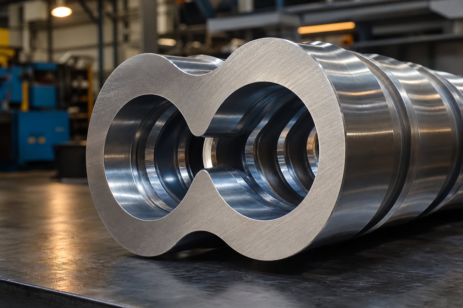
Cut a twin screw barrel in half at any point along its length and you won't find a round hole. You'll find a figure-eight — two overlapping circular bores fused together to create a cross-section unlike anything in single screw extrusion. This geometry is so fundamental to how the twin screw and barrel system works that it's surprising almost nobody takes the time to explain it. Let's fix that.
How the Figure-Eight Bore Differs From Single Screw Cylinders
A single screw extruder barrel is straightforward: one cylindrical bore, one screw rotating inside it. The cross-section is a circle. Simple.
A twin screw barrel? Picture two circles pushed together until they overlap in the center. That overlapping region — where material passes from one screw channel to the other — is called the intermesh zone, and it changes everything about how extrusion barrels function.
Why can't you just drill two separate round holes side by side? Because the screws intermesh. Their flights interlock like gears, and that interlocking action demands a shared space where the two bores merge. The figure-eight profile provides exactly that: two distinct cylindrical channels connected by a precisely shaped opening where the screws overlap.
This intermesh zone is where much of the processing magic happens. In co-rotating systems, material is handed off from one screw to the other in this region, creating the self-wiping action that prevents stagnant buildup. In counter-rotating configurations, the nip area between the screws generates intense calendering forces. Either way, the geometry of the barrel bore at the intermesh region directly controls how material flows, mixes, and builds pressure.
Think of it this way: in a single screw extruder, the material can ride along with the screw and resist forward movement. In a twin screw system, the figure-eight bore forces material into a path it can't escape — polymer gets pushed from one screw channel into the other, creating positive displacement that keeps everything moving forward regardless of viscosity changes. As industry practitioners note, this figure-eight flow path increases residence time for better plasticization while preventing material from simply rotating with the screw.
Bore Tolerances and Their Impact on Process Quality
Here's where theory meets the shop floor. The clearance between each screw flight tip and the barrel's inner bore wall is measured in fractions of a millimeter — and that tiny gap governs everything from melt seal integrity to output consistency.
When an extruder screw and barrel are new, this clearance is tightly controlled. Typical values fall in the range of 0.15 mm to 0.30 mm depending on machine size, according to precision machining specialists. That narrow gap does three critical things:
- It maintains the melt seal between processing zones, preventing molten polymer from leaking backward past the screw flights.
- It ensures consistent pressure generation, which drives stable throughput and uniform die filling.
- It controls the shear rate at the barrel wall, directly influencing melt temperature and mixing intensity.
As the bore wears — and it will, especially in high-pressure zones or areas handling abrasive glass-fiber compounds — that clearance grows. Even a seemingly small increase from 0.20 mm to 0.50 mm can break the melt seal, causing material to slip backward. You'll notice the symptoms quickly: reduced output rate, wider temperature variation across the melt, inconsistent pellet size, and surface defects in finished products.
The table below illustrates how bore condition relates to process performance and what action to consider at each stage:
| Bore Condition | Typical Clearance Range | Expected Performance Impact | Recommended Action |
|---|---|---|---|
| New / Within Specification | 0.15 – 0.30 mm | Full melt seal integrity; stable throughput and melt temperature; optimal energy efficiency | Continue monitoring on quarterly schedule |
| Early Wear | 0.30 – 0.50 mm | Slight reduction in conveying efficiency; minor melt temperature fluctuations begin to appear | Increase measurement frequency; plan replacement timeline |
| Moderate Wear | 0.50 – 0.80 mm | Noticeable output drop; inconsistent product quality; higher specific energy consumption | Schedule re-lining or segment replacement at next planned shutdown |
| Severe Wear / Out of Tolerance | > 0.80 mm | Melt seal failure; significant material leakage; product defects become unacceptable | Immediate replacement required to avoid screw damage and safety risk |
Wear doesn't happen evenly, either. It concentrates wherever the process is harshest — at feed port openings where abrasive fillers first contact the bore, in kneading block regions where shear forces peak, and at the intermesh zone itself. If the clearance becomes uneven due to poor original machining or localized wear, you get asymmetric melt flow, hotspots, and accelerated degradation of screw elements rubbing against barrel walls.
The bottom line? That figure-eight bore isn't just a shape — it's a precision-machined surface whose tolerances directly determine whether your extrusion barrels deliver stable, high-quality output or slowly bleed performance with every production hour. Maintaining bore geometry within specification is one of the highest-return maintenance investments a compounder can make.
Bore geometry and tolerances tell you how the barrel is built. But the story shifts when you consider that not all twin screw barrels share the same configuration — some run parallel, others taper conically, and the direction the screws rotate introduces an entirely different set of process dynamics.
Parallel vs Conical and Co-Rotating vs Counter-Rotating Configurations
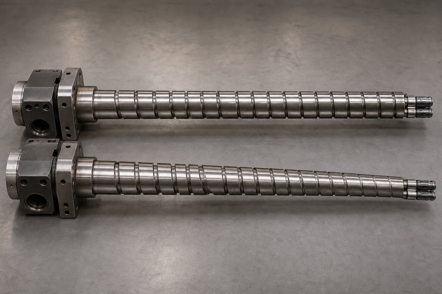
Every twin screw barrel shares that distinctive figure-eight bore — but the shape of that bore along the barrel's length, and the way pressure distributes across it, varies dramatically depending on configuration. Two screws can sit side by side at a constant diameter or taper from wide to narrow. They can spin in the same direction or oppose each other. Each combination reshapes the barrel's internal geometry, its wear profile, and the processing behavior it delivers.
Most resources lump these differences under "extruder types" and talk exclusively about the screws. The barrel itself — the stationary half of the equation — gets overlooked. Yet it's the barrel bore that must be precision-machined to match each configuration, and it's the barrel that absorbs the consequences when pressure, heat, and abrasion hit differently in each design.
Parallel vs Conical Barrel Geometry
A parallel twin screw extruder barrel maintains a constant bore diameter from the feed throat all the way to the discharge end. The two figure-eight channels run at a fixed center-to-center distance throughout the full length. This uniformity is what makes modular barrel segmentation possible — you can bolt together individual segments in different sequences because every segment shares the same bore dimensions.
A conical twin screw extruder barrel, by contrast, tapers. The bore diameter is largest at the feed end and progressively narrows toward the die. Imagine looking down the barrel from the feed side: the figure-eight profile gradually shrinks as it moves away from you. The two screw axes aren't parallel — they converge at an angle, which means the center distance between them also decreases along the barrel's length.
Why does this matter at the barrel level? The tapering bore creates a natural compression ratio built directly into the barrel geometry. As material travels from the wide feed zone toward the narrower discharge, it's physically squeezed into a smaller volume — generating pressure without requiring aggressive screw element designs or high screw speeds. This makes conical barrels especially well-suited for processing heat-sensitive materials like PVC, where gentle plasticization and high conveying force at low rotational speeds are critical to avoiding thermal degradation.
Conical barrels also show up frequently in recycling applications. Contaminated or inconsistent feedstock benefits from the gradual compression and lower shear environment that the tapered bore provides. The trade-off? A conical barrel is a one-piece design — you can't reconfigure segments or adjust the L/D ratio the way you can with a parallel system. Once the bore geometry is machined, it's fixed for that application.
Parallel barrels, on the other hand, offer flexibility that conical designs simply can't match. The L/D ratio can be increased or decreased by adding or removing barrel segments, and the screw profile can be completely rearranged to suit different formulations — all within the same barrel bore diameter. That adaptability is why parallel configurations dominate compounding, masterbatch production, engineering plastics, and reactive extrusion.
Co-Rotating and Counter-Rotating Barrel Bore Differences
Screw rotation direction might seem like a screw-only concern, but it fundamentally changes what happens inside the barrel bore — particularly at the intermesh zone discussed in the previous section.
In a co-rotating twin screw extruder, both screws turn the same way. Material follows an "infinity" or figure-eight flow path, transferring continuously from one screw channel to the other as it moves through the intermesh region. This creates a self-wiping action — each screw effectively cleans the other's surface and the adjacent barrel wall, preventing stagnant material from accumulating. From the barrel's perspective, this means wear distributes relatively evenly across the bore surface. Dead spots are minimized, so there's less risk of degraded material baking onto the barrel wall.
In a counter-rotating double screw extruder, the screws turn in opposite directions. Instead of that flowing figure-eight transfer, material gets trapped in roughly closed "C-shaped" chambers between the screw flights and the barrel bore. The nip region — where the two screws come closest together — generates intense calendering pressure as material gets squeezed between opposing flight faces. This is excellent for building pressure and achieving thorough compaction, but it concentrates mechanical stress on a narrow band of the barrel bore right at the intermesh zone.
The practical result? Counter-rotating barrel bores tend to wear preferentially at the nip region and in areas where the radial gap between screw outer diameter and the opposing screw root is tightest. Co-rotating barrels distribute wear more uniformly, but high-shear kneading block zones still represent localized wear hot spots.
The table below compares how these configurations shape the barrel's geometry, pressure behavior, wear patterns, and typical use cases:
| Configuration | Bore Geometry | Typical Pressure Profile | Primary Wear Zones | Common Applications |
|---|---|---|---|---|
| Parallel Co-Rotating | Constant-diameter figure-eight bore; fixed center distance along full length | Moderate, broadly distributed pressure; pressure builds primarily at restrictive screw elements (kneading blocks, reverse elements) | Kneading block regions; feed port openings where abrasive fillers enter; intermesh zone (evenly distributed due to self-wiping) | Polymer compounding, masterbatch, engineering plastics, reactive extrusion, devolatilization |
| Parallel Counter-Rotating | Constant-diameter figure-eight bore; fixed center distance; tighter intermesh clearances than co-rotating | High localized pressure at the nip region between opposing screw flights; strong positive displacement | Nip region of the intermesh zone; areas of highest calendering force; barrel bore adjacent to screw flight tips | PVC compounding, pipe and profile extrusion, highly filled compounds, calender feeding |
| Conical Counter-Rotating | Tapered figure-eight bore; decreasing diameter and center distance from feed to discharge | Gradually increasing pressure from feed to discharge due to natural bore compression; high discharge pressure at low screw speeds | Discharge (small-diameter) end where pressure peaks; feed zone where large-diameter flights contact the bore under bulk material loading | PVC pipe, PVC profiles, WPC (wood-plastic composites), recycling of heat-sensitive materials |
Notice how each configuration demands a barrel bore engineered to match its specific pressure and wear characteristics. A co-rotating and counter-rotating twin screw extruder may share the same general concept — two screws inside a figure-eight housing — but the barrel's internal geometry, tolerance requirements, and expected service life differ significantly between them.
Choosing the right configuration is a process-level decision with direct barrel-level consequences. A parallel co-rotating barrel gives you modularity and even wear distribution. A conical counter-rotating barrel gives you built-in compression and gentle processing — but locks you into a fixed geometry. Understanding these barrel-level distinctions ensures you're not just selecting a screw type; you're selecting the barrel architecture that will define your extruder's flexibility, maintenance schedule, and long-term performance.
Configuration determines the barrel's overall shape — but the real versatility of modern twin screw systems comes from what happens within that shape: individual barrel segments, each designed for a specific process function, bolted together in sequences that can be rearranged to match virtually any formulation.
Modular Barrel Segments and Zone Configuration
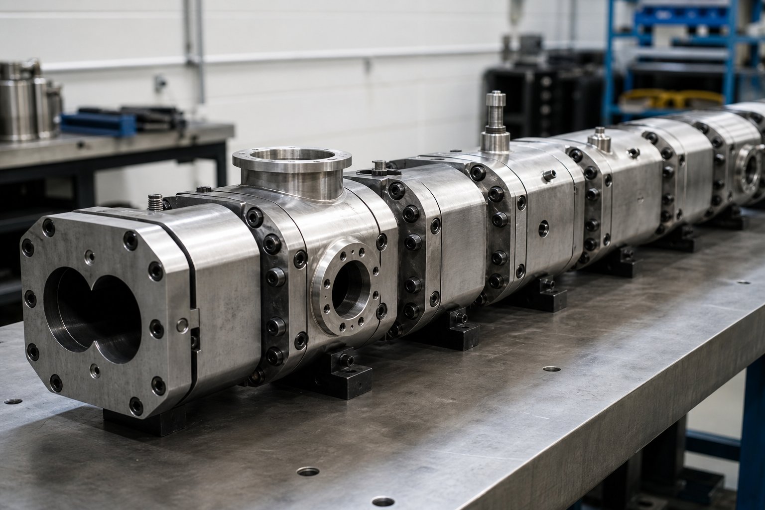
Picture a twin screw barrel as a single, monolithic steel tube and you've already made your first mistake. Modern parallel twin screw barrels are not one continuous piece. They're assembled from individual barrel segments — precision-machined blocks bolted together end to end in a deliberate sequence. Each block can serve a completely different process function, and rearranging them transforms the same extruder system into a fundamentally different processing line.
This modular concept is arguably the single biggest reason the twin screw compounding extruder dominates polymer compounding, masterbatch production, and reactive extrusion. Yet most resources skip right past it. Let's break it down.
How Segmented Barrels Enable Flexible Process Design
Each barrel segment is typically 4 to 5 L/D in length — meaning a segment on a 40 mm machine would be roughly 160 to 200 mm long. String eight to ten segments together, and you have a process section of 32/1 to 50/1 L/D. Need a longer residence time or additional unit operations? Add more segments. Need a shorter, simpler process? Remove a few.
What makes this powerful is that every segment in the lineup can perform a distinct role. There are four primary segment types you'll encounter:
- Closed barrel segments — Fully enclosed figure-eight bores with no external openings. These handle conveying under pressure, melting, and intensive mixing where the polymer melt must remain sealed inside the bore.
- Feed port segments — Open at the top with a machined port that allows raw materials to enter the screw channels. The main feed port sits at the first barrel position, but additional feed ports can be placed downstream for staged material addition.
- Side-stuffer segments — Feature a secondary figure-eight opening on the side of the barrel body, designed to connect a side stuffer — a small co-rotating twin screw auger that pushes fillers, fibers, or additives directly into the melt stream at a downstream location. This avoids exposing sensitive additives to the high-shear melting zone.
- Vent port segments — Open sections that allow trapped air, moisture, or volatiles to escape. These can operate at atmospheric pressure or connect to vacuum pumps for active volatile extraction.
Every one of these segments has its own independent heating and cooling zones. That means temperature control isn't just a barrel-level setting — it's a segment-level setting, giving processors zone-by-zone thermal management across the entire process length.
Matching Barrel Segments to Screw Element Zones
Here's where the real engineering happens. You can't just bolt barrel segments together in any order and expect good results. Each barrel port must align precisely with the right screw element zone underneath it — get this relationship wrong, and you'll fight material backup, vent flooding, or incomplete mixing for as long as the line runs.
The rules are straightforward but non-negotiable:
- Feed port segments must sit above conveying (forwarding) screw elements. These high-pitch flights create a starved, low-pressure zone that pulls material in rather than pushing it back out the port.
- Vent port segments require low-pressure melt seal zones beneath them. Upstream of the vent, restrictive elements like reverse kneading blocks or reverse-pitch flights build a melt seal that prevents polymer from traveling backward. Downstream, forwarding elements pull the melt away. The vent itself sits in the pressure valley between these two zones.
- Side-stuffer segments need specific screw configurations to prevent material backup into the stuffer. Typically, conveying elements beneath the side-feed port create enough drag flow to pull additives into the melt stream without allowing molten polymer to push up into the stuffer barrel.
Sounds complex? It's actually quite logical once you see a typical layout. Here's a representative barrel segment sequence for a standard compounding extruder line producing filled or reinforced pellets:
- Segment 1: Main feed barrel — Open top port receiving polymer pellets and powdered additives from loss-in-weight feeders.
- Segments 2-3: Closed conveying and melting barrels — Sealed segments where forwarding elements and kneading blocks melt the polymer base and begin initial mixing.
- Segment 4: Side-feed barrel — Secondary opening for a side stuffer introducing glass fibers, mineral fillers, or other downstream additives that would degrade or cause excessive wear if fed through the main melting zone.
- Segments 5-6: Closed mixing barrels — Sealed segments housing distributive and dispersive mixing elements that incorporate the side-fed additives thoroughly into the melt.
- Segment 7: Vacuum vent barrel — Open port connected to a vacuum pump, positioned above a low-pressure melt seal zone to extract moisture, entrapped air, and volatile contaminants.
- Segment 8: Closed metering and discharge barrel — Final sealed segment where forwarding elements build pressure to push the melt through the die plate, strand die, or into a screw extruder granulator for pelletizing.
This eight-segment layout is a starting point, not a fixed rule. That's the beauty of modular design — the same compounding extruder hardware can be reconfigured to process entirely different formulations simply by rearranging barrel segments and swapping screw elements. Need to add a second side-stuffer for a formulation with two different fillers? Insert another side-feed barrel segment and extend the process length. Processing a hygroscopic resin that requires extra devolatilization? Add an atmospheric vent barrel upstream and a second vacuum vent downstream. Running a simple color concentrate that needs no fillers and minimal venting? Remove the side-feed and vent segments to shorten the barrel, reduce residence time, and cut energy costs.
This reconfigurability is especially valuable in contract compounding and product development environments, where a single extruder system may handle dozens of different recipes across a production schedule. Rather than dedicating separate machines to each product family, processors invest in a comprehensive set of barrel segments and screw elements that can be assembled into whatever process configuration the next job demands. In downstream pelletizing operations — whether using strand cutting, underwater pelletizing, or a screw extruder granulator — the barrel configuration upstream directly determines melt quality, consistency, and throughput stability at the die face.
Reconfiguring segments changes what happens inside the barrel. But the barrel's ability to survive what happens inside — the abrasive fillers scraping the bore, the corrosive polymers attacking the surface — depends entirely on what the barrel is made of, a subject that connects barrel metallurgy and liner technology directly to processing economics.
Barrel Metallurgy and Wear-Resistant Liner Selection
A perfectly configured barrel layout means nothing if the bore surface can't survive what your formulation throws at it. Glass fibers grind like sandpaper. PVC releases hydrochloric acid. Recycled feedstock introduces mystery contaminants that attack the bore in unpredictable ways. The metallurgy of your twin screw barrel — specifically, what the bore surface is made of — determines whether the barrel lasts years or months. And that difference has a direct, measurable impact on your bottom line.
Base Barrel Materials and Bimetallic Liners
Every barrel starts with a structural body. This outer shell is typically manufactured from nitrided tool steel such as 38CrMoAlA or high-strength alloy steel like SKD61 (H13). The body provides mechanical strength — it's the pressure vessel that holds everything together under the forces generated during extrusion. But strength alone doesn't protect the bore surface from the abrasive, corrosive, and thermally aggressive materials flowing through it.
That's where bore surface treatments and liners come in. There are three broad categories, each matched to a different level of processing severity:
- Nitrided steel — The base barrel material itself undergoes gas nitriding, which hardens the bore surface to approximately 900-1000 HV (Vickers hardness). This treatment penetrates only about 0.5 mm deep. It's cost-effective and perfectly adequate for general-purpose extrusion of unfilled polymers like PE, PP, and PS — the workhorse resins that don't carry abrasive fillers or corrosive byproducts. Any screw plastic extruder processing virgin commodity resins can run reliably on nitrided barrels for extended periods.
- Bimetallic liners — A wear-resistant alloy is centrifugally cast onto the inner bore surface, creating a liner that's 1.8 to 3 mm thick — several times deeper than nitriding penetrates. Iron-based alloys like Colmonoy 56 handle moderate abrasion from calcium carbonate or talc-filled compounds. Nickel-based alloys resist chemical attack from corrosive polymers. For the most punishing applications — glass-fiber-reinforced engineering plastics, mineral-filled compounds — tungsten carbide particles suspended in a nickel-cobalt-chromium matrix deliver the highest abrasion resistance available.
- Specialty ceramic or carbide liners — Reserved for extreme cases where standard bimetallic liners still wear too quickly. These are less common but increasingly relevant as filler loadings rise and recycled content introduces harder contaminants.
The centrifugal casting process that produces bimetallic liners is itself a quality variable. As Nordson's engineering team explains, the composition, uniform thickness, and porosity of the inlay are critical determinants of barrel life — and the ideal inlay thickness sits at approximately 1.6 mm (0.063 in.), beyond which returns diminish. Induction furnaces produce more consistent results than traditional gas-fired methods, particularly for larger barrels used in high-throughput polymer extruder installations.
Selecting Barrel Materials for Specific Applications
Choosing a liner isn't about picking the "best" material in absolute terms. It's about matching the liner to your specific processing challenge. A tungsten carbide liner on a line running unfilled polyethylene is overkill that wastes money. A nitrided barrel on a line compounding 40% glass-fiber-reinforced nylon is a guaranteed failure within months.
The following table maps liner types to the applications where they deliver the best return:
| Liner Material | Typical Hardness | Best Suited Applications | Relative Cost Tier |
|---|---|---|---|
| Nitrided Steel (38CrMoAlA) | 900-1000 HV (surface) | General-purpose extrusion of unfilled PP, PE, PS; low-abrasion compounding; economical extruder for polymer development runs | $ (Low) |
| Iron-Based Bimetallic (e.g., Colmonoy 56/83) | 55-62 HRC | Moderately abrasive compounds with CaCO3, talc, or low-percentage mineral fillers; recycled plastics with moderate contamination | $$ (Medium) |
| Nickel-Based Bimetallic (Ni-Cr-B alloys) | 50-58 HRC | Corrosive polymers including PVC, CPVC, fluoropolymers; flame-retardant compounds releasing acidic byproducts; polyester extruder lines processing PET or PBT with hydrolysis risk | $$$ (Medium-High) |
| Tungsten Carbide in Ni-Co-Cr Matrix | 60-68 HRC | Highly abrasive glass-fiber-filled PA, PC, PPS; high mineral filler loadings (40%+); recycled materials with unknown hard contaminants | $$$$ (High) |
Notice the pattern: as processing severity increases — more abrasive fillers, more corrosive chemistries, more contaminated feedstock — the liner hardness climbs and so does the cost. That upfront cost, however, tells only half the story.
Consider the total cost of ownership. A nitrided barrel for a glass-fiber compounding line might cost a third of a tungsten carbide-lined alternative. Sounds like a bargain — until it wears out in 12 to 18 months and forces an unplanned shutdown for replacement. The bimetallic alternative, running the same application, typically lasts three to five years. Factor in lost production during changeover, expedited shipping for emergency replacements, and the gradual quality degradation that occurs as bore wear creeps beyond tolerance — and the "cheap" barrel often costs 50 to 70% more over its lifetime than the premium option.
This calculation shifts further when you run a polyester extruder or any line processing hygroscopic engineering resins at elevated temperatures. Corrosion and abrasion work together in these environments, accelerating wear rates beyond what either mechanism would produce alone. A nickel-based bimetallic liner handles the chemical attack while embedded carbides resist mechanical wear — a combination that straight nitriding simply cannot match.
The takeaway for procurement teams is straightforward: specify the liner for the application, not the purchase order. A barrel that survives the process environment year after year protects not just the bore surface — it protects throughput, product quality, and the maintenance budget that funds everything else on the plant floor.
Metallurgy keeps the bore intact against mechanical and chemical attack. But there's another threat to product quality that no liner can solve — trapped moisture, residual monomers, and entrapped gases that must be physically extracted from the melt before it reaches the die. That's the job of the barrel's venting system, and its design is far more nuanced than simply cutting a hole in the top of a segment.
Barrel Venting Systems for Volatile Removal and Process Control
A flawless bore surface and a perfectly sequenced barrel layout still can't save your product if moisture, trapped air, or residual volatiles ride along inside the melt all the way to the die. Bubbles, voids, splay marks, degraded molecular weight — these defects don't come from worn screws or misaligned segments. They come from gases that never had a way out. The barrel's venting system provides that escape route, and how it's designed, positioned, and managed separates a clean, dense pellet from one riddled with quality problems.
Many twin screw extruders ship with vent ports already machined into specific barrel segments. Yet surprisingly few operators fully understand why those ports sit where they do, what determines whether atmospheric or vacuum venting is appropriate, or what to do when melt starts creeping up through the opening instead of staying in the screw channels where it belongs.
Atmospheric Venting vs Vacuum Venting
There are two fundamental approaches to removing volatiles from the barrel, and most compounding lines use both — sometimes on the same machine.
Atmospheric vents are the simpler of the two. These are open ports in the barrel segment that allow trapped air and light volatiles to escape under ambient pressure. No pumps, no plumbing — gases simply vent to the atmosphere through the barrel opening. You'll typically find atmospheric vents near side-feeder locations, where large volumes of air enter the barrel along with powdered fillers like talc, calcium carbonate, or mineral additives. The lower the bulk density of the filler, the more air gets dragged into the screw channels, and the more vent area is needed to let it back out.
Atmospheric venting works well for entrained air and lightly volatile components, but it has limits. It can't extract moisture that's chemically bound within polymer chains, and it can't pull out residual monomers or solvents that require a pressure differential to release from the melt.
Vacuum vents solve that problem. Connected to vacuum pumps, these ports actively pull gases out of the melt by reducing the pressure above the exposed polymer surface — typically operating at 20 to 27 in. Hg (approximately 100-300 mbar). This additional driving force dramatically improves mass transfer, pulling moisture, entrapped gases, and residual monomers out of the melt far more effectively than atmospheric venting alone.
When does vacuum venting become essential rather than optional? Consider these scenarios:
- Hygroscopic polymers — Nylon (PA6, PA66), polycarbonate, PET, and PBT absorb atmospheric moisture that causes hydrolysis during processing. Vacuum venting removes this moisture directly from the melt, protecting molecular weight and mechanical properties.
- Recycled materials — Post-consumer and post-industrial recyclate often carries residual moisture, contaminants, and volatile degradation byproducts that atmospheric venting alone cannot adequately remove.
- Devolatilization applications — Processes that require extraction of solvents, residual monomers, or reaction byproducts depend on vacuum to create the partial pressure differential needed for efficient volatile removal.
Many screw extruder configurations use multiple vacuum vents in series — each preceded by its own melt seal zone — to achieve progressively lower residual volatile levels. Some lines even inject water or other stripping agents upstream of the vacuum vent, reducing the partial pressure of the target volatile species and further improving extraction efficiency.
Vent Port Design and Vent Stuffer Integration
Cutting a hole in a barrel segment sounds simple. In practice, vent port engineering is one of the most detail-sensitive aspects of twin screw barrel design — because the port must let gases out without letting melt escape.
Vent ports are machined into specific barrel segments, and their position relative to the screw element zones beneath them is absolutely critical. The operating principle is straightforward: the screw channel under the vent opening must be only partially filled with material. A melt seal — a fully filled section of screw created by restrictive elements like reverse kneading blocks — must exist upstream of the vent to prevent polymer from traveling backward toward the opening. Downstream, forwarding elements pull melt away from the vent zone, keeping the pressure low and the screw channels partially empty right where the port sits.
Get this alignment wrong, and you'll face every compounder's headache: vent flooding.
Vent flooding occurs when molten polymer rises up through the vent opening instead of staying in the screw channels. It blocks the port, prevents gas removal, contaminates the product with degraded material, and — in severe cases — forces a line shutdown for manual cleanup. According to processing experts at ENTEK, vent flow is one of the most common operational challenges on extruder twin screw compounding lines, and it stems from several root causes:
- Excessive downstream pressure from screen pack fouling or frozen die holes pushes the backup length of filled screw upstream until it reaches the vent opening.
- Worn screw elements or barrel bores reduce pumping efficiency, increasing the fill level in the vent zone.
- Insufficient melt seal pressure upstream allows vacuum to pull melt out of the screw channels.
- Viscosity changes from formulation adjustments or feed instability alter the fill level unpredictably.
For standard atmospheric vents, careful screw design and port positioning are usually sufficient to prevent flooding. Vacuum vents, however, face an additional challenge: the vacuum itself can actively suck melt up through the port. Some specialty materials — particularly those that foam or expand when exposed to vacuum at processing temperatures — will climb out of the screw channels under virtually any operating condition when using a conventional open vent port.
The solution? Vent stuffers. These are small twin screw augers mounted directly into the vent opening — either on top of or on the side of the barrel segment. The counter-rotating screws of the vent stuffer act as a mechanical barrier, physically pushing expanding melt back into the main extruder's screw channels while still allowing volatile gases to travel axially through the stuffer's screw flights and escape to the vacuum system. Imagine a revolving door that lets air through but blocks anything solid — that's essentially what a vent stuffer does for twin screw extruders.
Beyond stuffers, a range of specialty vent port designs have evolved to handle specific challenges. Heated side vents prevent polymer from accumulating and degrading within the port — eliminating the black specks that plague sensitive applications. Elongated vent barrels provide greater open area for high-volume degassing. Each design targets a particular failure mode that standard top-mounted ports can't fully address.
Whether you're running atmospheric or vacuum venting, the following design considerations determine whether your vent system performs reliably or becomes a constant source of production headaches:
- Port geometry and size — Larger openings reduce exit velocity of escaping gases, minimizing the tendency to entrain fines or powder. Applications with high-volume air removal from low-bulk-density fillers may require multiple atmospheric vent ports.
- Positioning relative to melt seal elements — The vent must sit in a verified low-pressure zone between an upstream melt seal and downstream forwarding elements. Misalignment by even one barrel segment can cause chronic flooding.
- Vent stuffer requirements — Any vacuum vent processing materials prone to foaming, expansion, or high-viscosity swell under reduced pressure should be equipped with a mechanical vent stuffer.
- Vacuum level targets — Standard compounding operations typically run at 20-27 in. Hg. Higher vacuum improves volatile removal but increases the risk of pulling melt through an inadequate seal. Matching vacuum level to melt seal capability is essential.
- Condensation management for volatiles — Extracted vapors condense in vacuum lines and pumps. Without proper knock-out pots, cold traps, or heated vacuum piping, condensate builds up, reduces vacuum efficiency, and can back-flow into the barrel.
Effective venting is ultimately a system-level challenge — it depends on screw design, barrel port placement, vacuum hardware, and process parameters all working in coordination. A well-designed vent system on twin screw extruders doesn't just remove volatiles; it protects downstream product quality at every stage from pelletizing through final part production.
Venting controls what leaves the barrel. But what about the energy flowing into and out of it? The barrel's heating and cooling systems govern melt temperature with zone-by-zone precision — and when that thermal management falls short, the defects that result look nothing like venting problems but can be equally devastating.
Barrel Heating and Cooling Systems for Temperature Precision
Every barrel segment on a twin screw extruder machine is simultaneously a heater and a heat sink. During startup, the barrel must push thermal energy inward to soften polymer. Minutes later, at steady state, those same segments may need to pull excess heat out to prevent degradation. This constant tug-of-war between adding and removing energy — happening independently across every zone — is what keeps melt temperature locked to setpoint and product quality consistent from the first pellet to the last.
Yet most extruder documentation glosses over barrel thermal systems entirely, treating them as accessories rather than core process components. That's a mistake. A barrel with the right bore geometry, the right liner, and perfectly positioned vent ports will still produce scrap if its heating and cooling can't hold temperature where the process demands it.
Barrel Heating Technologies and Zone Control
How does heat actually get into the barrel wall? Three technologies dominate, each with a distinct performance profile:
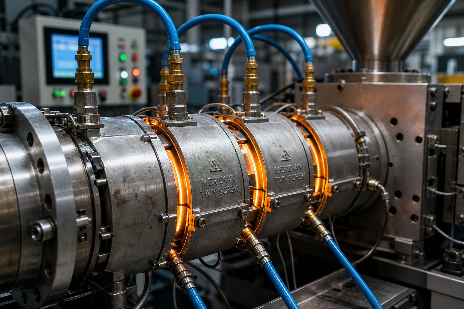
- Cast-aluminum or cast-bronze heaters — These band-style heaters are clamped directly around the outside of each barrel segment. They provide broad, even heat distribution across the segment surface and are the most common heating method on production twin-screw extruder machine platforms. Their thermal mass means they respond relatively slowly to setpoint changes, but they deliver stable, uniform heating once at temperature.
- Cartridge heaters — Cylindrical resistance elements inserted into drilled holes machined directly into the barrel body. Because the heating element sits inside the barrel wall rather than on its surface, thermal coupling is excellent — heat transfers efficiently into the bore with minimal surface losses. Cartridge heaters are common on smaller double screw extruder machine configurations and on barrel segments where space constraints prevent external band heaters.
- Induction heating — Electromagnetic coils induce eddy currents directly within the barrel steel, generating heat from the inside of the wall outward. Response time is dramatically faster than resistance heaters — the barrel can reach setpoint in a fraction of the time. Induction systems also reduce radiated heat into the plant environment, improving operator comfort and reducing facility cooling loads. The trade-off is higher upfront cost and more complex controls.
Regardless of which technology is used, the key architectural principle is the same: each barrel segment operates as an independent heating zone with its own temperature setpoint, thermocouple, and PID controller. A typical compounding line might have eight to twelve individually controlled zones along the barrel length, each dialed to a different temperature to match the processing requirements of the screw elements inside that segment.
Why does this zone-by-zone independence matter so much? Because the thermal demand shifts dramatically along the barrel. Feed zones need moderate heat to begin softening pellets without creating a molten plug that blocks incoming material. Melting zones may need higher temperatures — or none at all, if shear heat from kneading blocks is already generating more than enough energy. Metering zones near the die require tight temperature control to deliver a uniform melt for consistent die flow. A single barrel-wide temperature setting could never accommodate these competing demands.
Heat-up uniformity is another factor that separates reliable production from frustrating startups. If one side of a barrel segment heats faster than the other — due to poor heater contact, an air gap between the heater band and the barrel surface, or a failed heating element — the bore expands unevenly. That asymmetric expansion can tighten clearance on one side while opening it on the other, creating conditions for metal-to-metal contact between screw flights and the barrel wall before the machine even reaches operating temperature.
Liquid Cooling Channels and Thermal Management
Heating gets all the attention, but on a well-tuned twin screw extruder machine running at steady state, the heaters are barely working. The real thermal challenge is removing heat — specifically, the shear heat generated by viscous dissipation as screws force polymer through tight clearances and kneading elements.
Each barrel segment contains internal cooling channels — passages drilled or cast into the barrel body through which water or thermal oil circulates. When a zone's thermocouple detects temperature rising above setpoint, the controller opens a solenoid valve or modulates a proportional valve to increase coolant flow through that segment's channels. The coolant absorbs excess thermal energy from the barrel wall and carries it away to a heat exchanger or cooling tower.
This interplay between heating and cooling creates a dynamic thermal balancing act. During startup, heaters run at full power while cooling valves stay closed — the barrel needs every watt to reach processing temperature. As the screws begin turning and polymer fills the channels, shear heat kicks in. In high-intensity mixing zones, shear-generated energy can exceed what the heaters contribute, pushing zone temperatures above setpoint. The heaters back off, cooling valves open, and the barrel shifts from net heat supplier to net heat remover — sometimes within the same production run.
The choice of cooling medium matters more than many operators realize. Water removes heat aggressively, which is an advantage in high-shear zones but carries a risk: over-response can strip away so much energy that the drive motors essentially work against the cooling system, wasting electricity generating shear heat that the coolant immediately removes. Oil circulates at lower heat transfer rates, providing gentler, more controllable cooling — particularly valuable for heat-sensitive materials like PVC where temperature overshoot triggers degradation.
Several factors determine how effectively a barrel segment manages thermal energy. If any one of them is poorly designed or degraded, temperature control suffers:
- Heater watt density — The power output per unit area of the heating element. Too low, and the zone can't reach setpoint during startup or recover from process upsets. Too high, and localized hot spots develop on the barrel surface.
- Cooling channel diameter and flow rate — Undersized channels restrict coolant flow, limiting heat removal capacity. Scaled or corroded channels — a common problem in plants with poor water treatment — reduce effective diameter over time, gradually degrading cooling performance.
- Barrel wall thickness between bore and cooling channel — This dimension controls how quickly thermal energy transfers from the polymer-contacting bore surface to the coolant. A thicker wall adds thermal resistance, slowing response time. A thinner wall improves response but reduces mechanical strength.
- Thermal coupling between heater and barrel surface — Any air gap between a band heater and the barrel segment acts as insulation, reducing heat transfer efficiency and creating uneven temperature distribution around the bore circumference. Proper heater fit and consistent clamping torque are essential.
When thermal management fails — whether from a burned-out heater, a scaled cooling channel, or a controller tuned too loosely — the consequences show up in the product, not on the control panel. Overheating in a mixing zone causes thermal degradation: discoloration, reduced molecular weight, brittleness, and in severe cases, charred particles contaminating the melt stream. Undercooling in the metering zone allows melt temperature to drift upward, producing die drool, inconsistent strand diameter, and poor pellet geometry.
The opposite failure — insufficient heating in the melting zone — leaves unmelted particles, or "unmelt," embedded in the extrudate. These show up as gels, hard spots, or surface roughness in finished parts. Either direction of thermal error degrades quality, and both are preventable with properly designed and maintained barrel heating and cooling systems.
Thermal precision keeps the process running within specification today. But the barrel itself doesn't stay in specification forever — wear accumulates zone by zone, hour by hour, and knowing exactly when to measure, when to re-line, and when to replace is the difference between planned maintenance and emergency downtime.
Barrel Wear Inspection and Maintenance Lifecycle
Thermal systems keep the process stable hour by hour. But barrel wear operates on a different timescale — it accumulates gradually, invisibly, millimeter by millimeter, until one day throughput drops, pellet quality drifts, and operators start chasing phantom problems with screw speed adjustments that only accelerate the underlying damage. The difference between a plant that replaces barrels on its own schedule and one that scrambles through emergency shutdowns comes down to one thing: structured wear inspection.
Barrel maintenance is the most neglected discipline in screw extrusion operations. Processors meticulously track screw element condition, gearbox oil quality, and die performance — yet the barrel bore that surrounds everything often goes unmeasured until symptoms become impossible to ignore. By that point, the damage has already cost weeks of degraded output and compromised product quality.
Bore Diameter Measurement and Wear Assessment
How do you know when a barrel is wearing out? You measure it. Not with assumptions, not by watching output trends, and not by waiting for customer complaints — you physically measure the bore diameter at regular intervals along the barrel's length and compare those numbers against the original specification.
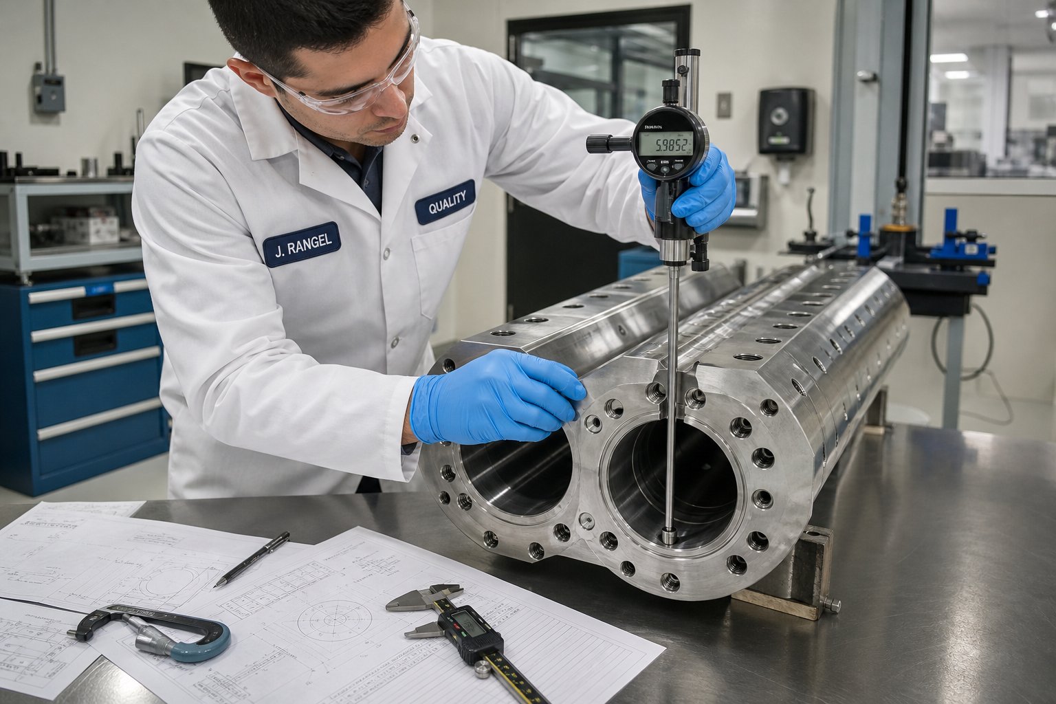
The standard tool for this job is an internal bore gauge — a precision instrument inserted through the barrel bore that reads the diameter at specific axial positions. For smaller twin-screw extruder models with screw diameters up to 170 mm, Coperion's diagnostic approach uses a bore measurement device combined with a high-resolution video camera mounted on a specially constructed slide. As the camera moves through the process section, it captures HD-quality images of the entire bore surface — revealing scoring, pitting, erosion patterns, and surface damage that dimensional measurement alone might miss.
For larger machines — sizes ranging from 240 mm through 420 mm screw diameter — the analysis goes further. Laser-supported surface measurement precisely maps either the entire internal bore or selected high-risk areas, and dedicated software processes the results into three-dimensional graphics showing the actual wear state. Combined with video documentation, this provides a comprehensive optical analysis that enables early identification of surface damage before it reaches critical levels.
Here's the critical insight most operators miss: wear is not uniform along the barrel length. It concentrates in predictable — but often overlooked — locations:
- High-pressure zones — Wherever restrictive screw elements like reverse kneading blocks or throttle elements build pressure, the melt pushes harder against the barrel wall. Higher contact force means faster material removal from the bore surface.
- Extruder feed barrel openings — The point where abrasive fillers like glass fiber, mineral powders, or recycled flake first contact the bore surface. Material entering through feed ports and side stuffers hasn't yet been wetted and encapsulated by the melt — dry, angular particles scrape directly against bare metal. This makes feed zones and side-stuffer entry points among the fastest-wearing locations on any compounding line.
- Kneading block regions — High shear intensity and elevated local pressures in these mixing zones accelerate bore erosion, particularly when processing abrasive formulations at high screw speeds.
- The intermesh zone — Where the two bores overlap, complex flow patterns and material transfer between twin screws create localized stress on the barrel surface that differs from the rest of the bore circumference.
Because wear concentrates unevenly, a single measurement at mid-barrel tells you almost nothing useful. Effective bore assessment requires measurements at multiple axial positions — ideally at every barrel segment — and at multiple angular positions around the bore circumference. You're looking for both overall diameter growth (indicating general abrasive wear) and localized enlargement (indicating process-specific erosion patterns).
As explored in the bore tolerance section earlier in this article, clearance growth beyond specification degrades process performance progressively. The self-reinforcing degradation cycle is particularly insidious: increased clearance reduces pumping efficiency, which prompts operators to increase screw speed, which accelerates wear further. Catching this cycle early — before operators start compensating — is precisely why scheduled bore measurement matters.
Re-Lining vs Full Replacement Decision Framework
So the measurement data comes back and confirms what you suspected: bore wear exceeds tolerance in one or more zones. What now? You have two options — re-line the barrel or replace it entirely. The right choice depends on the type and severity of damage, not just the cost difference on a purchase order.
Re-lining — sometimes called re-boring and re-sleeving — involves machining out the worn inner wall and installing a new bimetallic liner. The process starts with boring the existing barrel to approximately one inch larger than the original bore diameter, cutting through the worn inlay and into the backing steel. A new bimetallic sleeve — typically about 0.5 inches in wall thickness — is precision-machined to an outer diameter tolerance of 0.001 inches, then secured inside the barrel through a heat-shrink interference fit. Final machining and polishing restore the bore to specification.
When done properly, re-lining can extend barrel service life at a significant cost savings. Industry estimates put the savings at 25% to 50% compared with purchasing a new barrel — though those economics depend heavily on barrel size, complexity, and the scope of repair needed.
But re-lining has real limitations. Straightness must be maintained to approximately 0.005 inches total indicator runout during the boring process, which requires specialized rigid boring machines. Even under the best conditions, a repaired barrel never quite achieves the degree of straightness, concentricity, strength, or heat transfer available with a new one. Poorly executed repairs introduce additional risks: air pockets between the liner and the outer barrel body cause heat transfer problems, while seams where a short sleeve meets the existing inlay create hang-up points where polymer degrades.
The following table outlines typical wear conditions, their observable symptoms, and the recommended path forward:
| Wear Condition | Symptoms Observed | Recommended Action | Approximate Cost Impact |
|---|---|---|---|
| Uniform bore wear within re-lineable range (diameter growth < 1.0 mm beyond spec) | Gradual output reduction; slight increase in specific energy consumption; minor melt temperature fluctuations | Re-bore and re-line with new bimetallic sleeve | 25-50% of new barrel cost; minimal downtime if spare barrel is available for swap |
| Localized wear at feed port or side-stuffer zone only | Material leakage at the affected segment; reduced conveying efficiency in feed zone; visible scoring at extruder feed barrel opening | Replace the affected barrel segment only (modular systems); short-sleeve re-line if monolithic barrel | 10-30% of full barrel replacement; fast turnaround if segment is stocked |
| Bore cracking or surface fractures | Unexpected pressure fluctuations; polymer leakage between barrel segments; visible cracks during bore inspection | Full replacement — cracks propagate under operating pressure and cannot be reliably repaired | 100% new barrel cost plus potential emergency expediting fees |
| Warped barrel alignment (measured straightness exceeds 0.005 in. TIR) | Accelerated screw element wear on one side; uneven wear pattern visible in bore measurement; intermittent metal-to-metal contact noise | Full replacement — re-lining cannot correct alignment distortion in the barrel body | 100% new barrel cost; delayed replacement risks screw damage adding 30-50% more to total repair bill |
| Worn-through liner exposing backing steel | Rapid diameter growth rate; ferrous contamination in extrudate (detectable by magnets or metal detectors); sharp increase in motor amperage | Full replacement — backing steel wears orders of magnitude faster than liner material, and re-lining over compromised backing steel risks liner separation | 100% new barrel cost; continued operation risks catastrophic bore failure |
Notice that three of the five conditions in the table require full replacement rather than repair. This is consistent with field experience: most barrels are replaced rather than repaired, particularly as the cost of new bimetallic barrels has decreased with modern manufacturing methods while performance demands have increased. The decision ultimately rests on whether the barrel body itself is structurally sound and geometrically straight — if those two conditions are met, re-lining can deliver genuine value. If either is compromised, repair is a gamble.
Preventive Maintenance Schedules
Reactive maintenance — waiting until something fails and then fixing it — is always more expensive than preventing the failure in the first place. This is doubly true for barrel wear, because the degradation is gradual and cumulative. By the time symptoms are obvious to an operator, weeks or months of suboptimal production have already passed.
A structured preventive maintenance schedule catches developing problems early, builds the trend data needed for replacement planning, and keeps barrel condition documented for quality audits. Industry maintenance frameworks emphasize that systematic measurement and observation reveal developing issues before catastrophic failure — and that without structured checklists, critical tasks fall to memory and individual judgment, creating inconsistency across shifts and sites.
The following schedule represents a practical starting point for twin screw barrel maintenance on production compounding lines. Adapt the frequencies to your specific operating intensity, material abrasiveness, and risk tolerance:
- Daily: Visual inspection of barrel segment joints — Check every segment-to-segment connection for signs of polymer leakage, discoloration, or heat damage. Look for material weeping at bolt flanges, which indicates seal degradation or segment misalignment. Verify that all heater bands are seated properly and that no cooling hoses show leaks or kinks. This takes minutes but catches problems that become shutdowns within days if ignored.
- Weekly: Temperature zone verification — Confirm that every barrel zone reaches and holds its setpoint within normal tolerances during stable operation. Record the actual vs. setpoint temperature for each zone. A zone that consistently runs above setpoint despite active cooling may indicate increased shear from tightening clearance — or a failing cooling channel. A zone that can't reach setpoint may have a burned-out heater or an air gap between the heater and the barrel surface.
- Monthly: Motor amperage trend review — Track drive motor amperage under standard operating conditions. Rising amperage at constant throughput and screw speed can indicate increasing barrel-screw friction from misalignment, thermal distortion, or material buildup. Falling amperage at constant speed may indicate loss of pumping efficiency from bore wear — the screws are doing less work because material is slipping backward through widened clearances.
- Quarterly: Bore diameter measurement at critical zones — Pull the twin screws, clean and cool the barrel, and measure bore diameter at the highest-wear locations identified from previous inspections — typically at feed openings, kneading block zones, and the intermesh region. Compare measurements to baseline values and previous quarters. Plot the trend. If wear rate is accelerating, investigate root causes (filler loading changes, screw speed increases, liner quality) and adjust your replacement timeline accordingly.
- Annually: Full-length bore inspection with documentation and trend tracking — Perform a comprehensive bore measurement at every barrel segment, supplemented by visual inspection using a borescope or video camera system. Document the condition with photographs and measurement data. Compare results against the full historical record for that barrel. This annual dataset becomes the foundation for predicting when each segment will reach its wear limit, enabling planned replacement during scheduled downtime rather than emergency response.
One practical tip that experienced maintenance teams swear by: keep a dedicated barrel logbook — physical or digital — for each machine. Record every bore measurement, every segment swap, every liner replacement, and every formulation change that ran through that barrel. Over time, this log reveals patterns invisible in day-to-day operations. You'll discover that certain formulations wear specific segments three times faster than others, or that a particular liner grade consistently outperforms alternatives in your process environment. That kind of data-driven insight transforms barrel maintenance from a reactive cost center into a predictable, optimized line item in the maintenance budget.
Barrel wear is not a failure — it's an expected outcome of processing abrasive, corrosive, and high-pressure materials. The failure is not measuring it, not trending it, and not planning for it.
Knowing when and how to maintain your barrel keeps existing equipment running at peak performance. But eventually, every barrel reaches end of life — and at that point, the specifications you write for its replacement determine whether the next barrel delivers years of reliable service or repeats the same wear problems on an accelerated timeline.
How to Specify and Source the Right Twin Screw Barrel
A barrel logbook tells you when to replace. But the replacement order itself — the document that lands on a manufacturer's desk — determines whether the next barrel delivers the same performance as the original, improves on it, or quietly introduces problems that take months to diagnose. An incomplete or imprecise specification is the most common root cause of barrel procurement failures, and it's entirely preventable.
Engineers and procurement professionals ordering twin screw barrels face a challenge that doesn't exist with most industrial spare parts: these are custom-manufactured, application-specific components whose critical dimensions, metallurgy, and port configurations must match both the machine and the process. Get one parameter wrong — a liner grade that doesn't resist your filler's abrasiveness, a vent port positioned one segment off from where the screw's melt seal sits — and you've purchased an expensive lesson in specification discipline.
The checklist below eliminates that risk. It covers every parameter a twin-screw extruder manufacturer or aftermarket barrel supplier needs to quote and build a barrel that drops into your machine and performs from the first run.
Essential Specifications for Twin Screw Barrel Orders
Whether you're replacing a worn barrel on an existing line, upgrading liner materials for a more abrasive formulation, or specifying barrels for a new twin screw extruder for sale in your facility, the same core specifications apply. Miss any of these, and you'll face delays, engineering back-and-forth, or — worse — a barrel that arrives and doesn't fit.
- Bore diameter and tolerance class — Specify the nominal bore diameter for each screw channel and the acceptable tolerance band (e.g., +0.00/-0.02 mm for new barrels). This is the single most critical dimension. If you're replacing a worn barrel and have measurement data from your bore inspection program, include the original specification, not the worn dimension.
- L/D ratio and number of segments — State the total process length as an L/D ratio (e.g., 40:1, 48:1) and the number of individual barrel segments. For modular parallel systems, include the length of each segment (typically 4D or 5D). If you're changing the L/D from the original configuration, note which segments are being added or removed.
- Barrel material and liner grade — Specify both the base barrel body material (e.g., 38CrMoAlA, 42CrMo, 1.8550) and the bore liner type (nitrided, iron-based bimetallic, nickel-based bimetallic, tungsten carbide composite). Include the target hardness range and minimum liner thickness. If you're unsure which liner grade suits your application, a competent supplier will recommend one based on the materials you process — but you need to tell them what those materials are.
- Port requirements — feed, vent, and side-stuffer positions — Identify exactly which barrel segments require open ports and what type: main feed port (segment position, opening dimensions), atmospheric vent ports, vacuum vent ports, side-stuffer ports (including stuffer mounting flange dimensions and orientation — left, right, or top). Include the angular position of each port relative to the barrel's alignment reference.
- Heating zone count and heater type compatibility — Specify the number of independent heating zones across the barrel length and the type of heating elements the barrel must accommodate: band heaters (note the barrel's outer diameter for proper heater sizing), cartridge heaters (note hole diameter, depth, and pattern), or induction coils. Include the electrical specifications — voltage, wattage per zone — if matching existing controls.
- Cooling channel specifications — State the cooling medium (water or oil), the channel diameter, the inlet/outlet port sizes and thread types, and any pressure or flow rate requirements. If your plant uses a specific connector standard (e.g., quick-disconnect fittings of a particular size), include that detail to avoid adapter headaches at installation.
- Alignment and concentricity requirements — Specify the maximum allowable bore straightness deviation (total indicator runout) across the full assembled barrel length, and the concentricity tolerance between the two figure-eight bore channels. Typical production-grade barrels hold 0.02-0.05 mm TIR; high-precision applications may demand tighter values.
- OEM compatibility dimensions — If the barrel must fit an existing machine frame, include the mounting bolt pattern, segment flange dimensions, dowel pin locations, and any machine-specific locating features. Reference the extruder OEM and model number. Barrels built to fit a Leistritz extruder, for example, use different flange geometry and alignment features than those designed for a Coperion extruder platform or a JSW machine. Providing a drawing or sample of the original barrel — even a worn one — eliminates dimensional ambiguity entirely.
Two additional pieces of information dramatically improve quote accuracy and turnaround time: the materials you process (polymer type, filler type and loading percentage, any corrosive additives) and the operating conditions (typical melt temperature range, screw speed range, throughput target). These don't appear on a dimensional drawing, but they're exactly what a knowledgeable barrel manufacturer uses to validate your liner selection and flag potential specification mismatches before production begins.
Sourcing Twin Screw Barrels From Specialized Manufacturers
Imagine ordering a precision hydraulic cylinder from a company that primarily makes structural steel beams. They might get the outer dimensions right, but bore finish, seal surface quality, and metallurgical consistency? Those require specialized knowledge and equipment that generalist fabricators simply don't possess.
The same principle applies to twin screw barrels. The bore geometry — that figure-eight profile discussed earlier — demands deep-hole boring equipment configured specifically for overlapping cylindrical channels. The bimetallic liner casting process requires precise control of centrifugal force, alloy temperature, and cooling rate to achieve uniform thickness and bond integrity. And the final bore finish must meet surface roughness specifications that affect both wear characteristics and polymer flow behavior.
Specialized barrel manufacturers offer several advantages over OEM replacement channels and general machining shops:
- Application-specific liner recommendations — Rather than offering a single standard liner, dedicated manufacturers maintain expertise across the full spectrum of bimetallic alloys and can match liner composition to your specific processing challenge. Running 30% glass-fiber-reinforced PA66? They'll specify tungsten carbide. Processing flame-retardant ABS with brominated additives? Nickel-based corrosion-resistant alloys become the right call.
- Tighter bore tolerances — Manufacturers whose core business is barrel production invest in boring and honing equipment optimized for this specific geometry. That translates to tighter as-new clearances, longer service life before wear reaches tolerance limits, and more consistent performance across the barrel length.
- Faster turnaround than OEM replacements — OEM lead times for barrel replacements can stretch to months, particularly for less common machine sizes. Specialized aftermarket manufacturers — many of whom supply barrels compatible with Coperion extruder platforms, Leistritz extruder models, KraussMaffei, and JSW machines — often deliver in a fraction of that timeline because barrel production is their primary workflow, not an ancillary service.
- Cost efficiency without quality compromise — The twin screw extruder price for a complete barrel set from the original equipment manufacturer often reflects brand premium and distribution margins. Aftermarket specialists compete on value — delivering equivalent or superior metallurgy and machining precision at a lower total acquisition cost.
For compounding plants, pelletizing lines, masterbatch producers, and recycling operations where barrel durability directly governs uptime and product consistency, sourcing from a manufacturer with deep application expertise is particularly important. NANHAIYA's parallel twin screw barrel solution exemplifies this approach — barrels developed specifically for high-wear processing environments that demand stable mixing, reliable conveying, and wear-resistant construction matched to the application rather than generic off-the-shelf builds. For operations running abrasive filled compounds or recycled feedstock that punishes standard liners, this kind of application-matched sourcing often delivers the lowest total cost of ownership over the barrel's full service life.
Regardless of which supplier you choose — OEM, aftermarket specialist, or regional manufacturer — the vetting process should confirm three things before you place an order. First, verify metallurgical capability: can the factory document the liner alloy composition, hardness testing, and bond integrity of the bimetallic layer? Second, confirm dimensional inspection: does the manufacturer measure and certify bore diameter, straightness, and concentricity on every barrel segment before shipment? Third, check application knowledge: can the technical team discuss your process conditions and confirm that the specified liner grade, port configuration, and thermal design match your actual operating environment?
A factory that can answer all three with documentation — not just promises — is a factory that builds barrels engineered to perform, not just barrels machined to fit.
Matching barrel specifications precisely to your process requirements — material grade, bore tolerance, port configuration, and thermal design — is the single most impactful decision for long-term extruder performance and uptime.
That principle runs through every section of this article, from figure-eight bore geometry to modular segmentation, from liner metallurgy to vent system design. The barrel is not a commodity. It is the engineered foundation on which every other component — screws, heaters, vacuum systems, and downstream equipment — depends. Specify it with the same rigor you apply to the screws inside it, source it from manufacturers who understand what they're building and why, and maintain it with the discipline of scheduled measurement and documented trends. Do those three things, and the barrel becomes what it was designed to be: the most reliable, longest-lasting, and highest-value component in your extrusion system.
Frequently Asked Questions About Twin Screw Barrels
1. What is the figure-eight bore in a twin screw barrel and why does it matter?
The figure-eight bore is the distinctive cross-sectional shape formed by two overlapping cylindrical channels machined into every twin screw barrel. This geometry creates an intermesh zone where material transfers between the two screws, enabling positive displacement and self-wiping action that single screw cylinders cannot achieve. The precision of this bore shape directly controls melt seal integrity, pressure generation, and mixing efficiency. Even minor deviations from specification — as little as 0.3 mm of additional clearance from wear — can degrade throughput stability and product quality.
2. How often should twin screw barrel bore diameter be measured?
A practical maintenance schedule includes quarterly bore diameter measurements at high-wear zones such as feed port openings, kneading block regions, and the intermesh area. A full-length bore inspection with documentation should occur at least annually. Daily visual checks of barrel segment joints for leaks and weekly temperature zone verification help catch early warning signs between formal measurements. Tracking these readings over time reveals wear rate trends that allow you to plan replacements during scheduled downtime rather than responding to emergency failures.
3. What is the difference between nitrided and bimetallic twin screw barrel liners?
Nitrided barrels have a surface-hardened bore created through gas nitriding, reaching about 900-1000 HV but penetrating only roughly 0.5 mm deep. They suit general-purpose extrusion of unfilled polymers like PE and PP. Bimetallic liners, by contrast, are centrifugally cast alloy layers 1.8 to 3 mm thick bonded to the bore surface. Iron-based bimetallic liners handle moderately abrasive fillers like talc, while tungsten carbide composite liners withstand highly abrasive glass-fiber-reinforced compounds. Bimetallic barrels cost more upfront but often deliver lower total cost of ownership because they last three to five times longer in demanding applications. Manufacturers like NANHAIYA offer application-matched barrel solutions with wear-resistant liners tailored to specific processing environments.
4. When should a twin screw barrel be re-lined versus fully replaced?
Re-lining is viable when bore wear is uniform and the barrel body remains structurally sound and geometrically straight — typically saving 25% to 50% compared with a new barrel. However, full replacement is necessary when bore cracking, warped alignment exceeding 0.005 inches TIR, or worn-through liners exposing backing steel are detected. These conditions cannot be reliably repaired because cracks propagate under operating pressure, alignment distortion persists through re-lining, and backing steel wears orders of magnitude faster than liner material. Bore measurement data and visual inspection together determine which path delivers the best return.
5. What causes vent flooding on a twin screw extruder and how is it prevented?
Vent flooding occurs when molten polymer rises through the barrel vent port instead of remaining in the screw channels. Common causes include excessive downstream pressure from screen pack fouling, worn screw elements reducing pumping efficiency, insufficient upstream melt seal pressure, and viscosity changes from feed instability. Prevention starts with correct vent port positioning relative to melt seal screw elements and adequate pressure management. For vacuum vents processing materials prone to foaming, mechanical vent stuffers — small twin screw augers mounted in the vent opening — physically push expanding melt back into the main barrel while allowing gases to escape to the vacuum system.
Written by
Nanhaiya Technical Team
Zhoushan Nanhaiya Plastic Machinery Co., Ltd.
The Nanhaiya technical team supports screw and barrel manufacturing projects through application review, technical communication, custom manufacturing coordination, and production and quality control.
Discuss Your Application
Related Articles
More insights on screw barrel technology and plastics processing.

What Nobody Tells You About Screw Barrel For Plastic Machine Design
Oct 10, 2026
Learn how screw barrel for plastic machine design affects melt quality, throughput, and wear life. Covers geometry, resin matching, troubleshooting, and sourcing.
Read Article
Single Screw Extruder for Sheet: Stop Guessing, Start Specifying
Oct 9, 2026
Learn how to specify a single screw extruder for sheet production. Covers screw geometry, resin-specific processing, troubleshooting, and maintenance best practices.
Read Article
PE Pipe Extruder Machine: What Datasheets Won't Tell You
Oct 9, 2026
Learn how a PE pipe extruder machine works, key specs explained, material grade selection, maintenance tips, and buyer guidance beyond the datasheet.
Read ArticleLooking for something else?
Search by material, symptom or product and jump straight to the relevant page.
These are navigation suggestions based on keyword matching — not a quotation, not a delivery commitment, and not a substitute for engineering review. Final specification is confirmed by our engineers against your drawings and processed material.
Need help with screw barrel selection?
Share your machine model, processed material and application. Our team can help with pricing and technical support.