

What a Barrel Extruder Is and Why It Matters
Imagine a component that simultaneously acts as a pressure vessel, a heat exchanger, and a containment chamber — all while enduring temperatures above 300 °C and internal pressures that can reach 400 bar. That component is the barrel extruder, and every plastics processing line depends on it.
Defining the Barrel Extruder and Its Core Functions
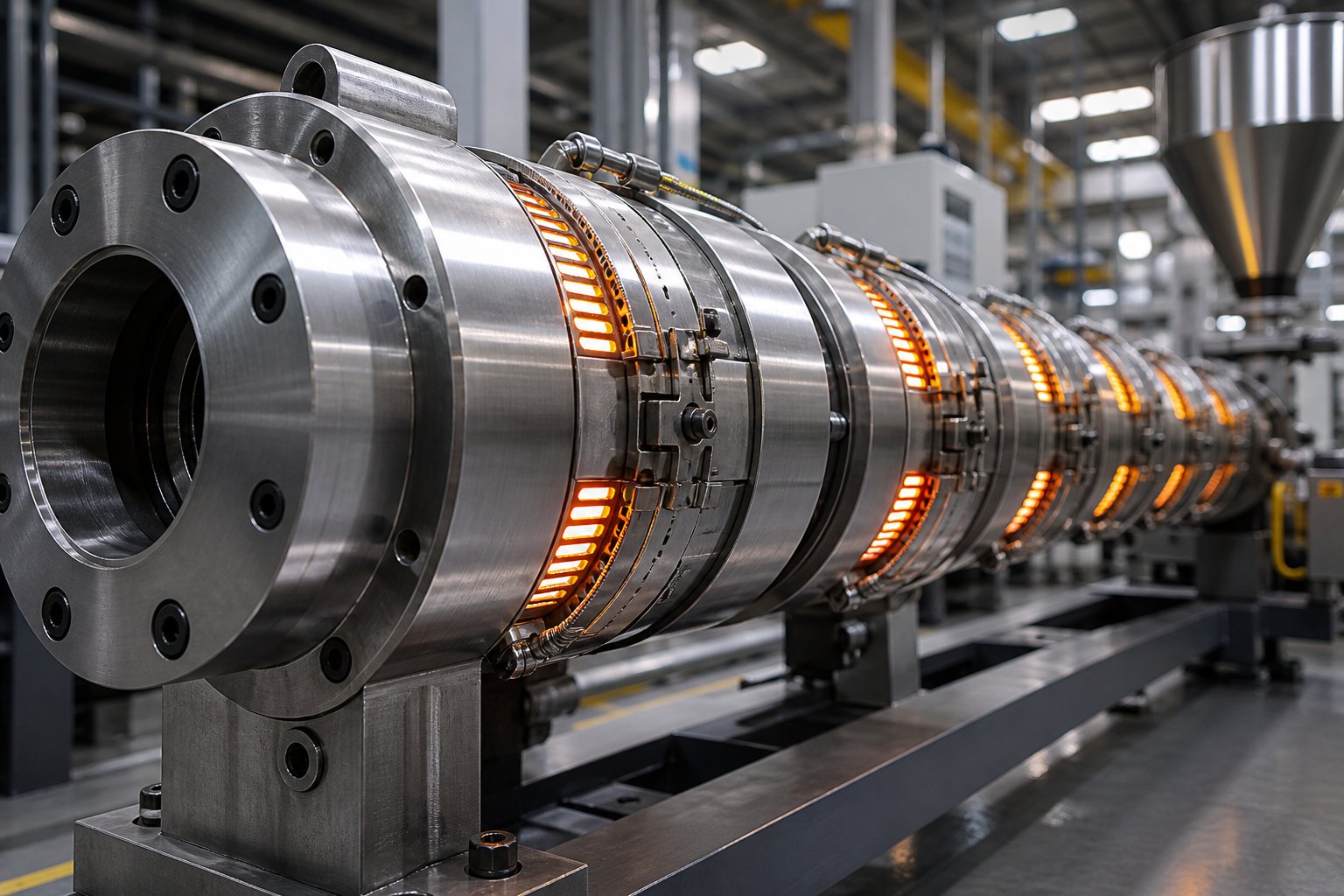
A barrel extruder is the cylindrical steel housing inside an extrusion machine through which a rotating screw conveys, compresses, melts, and pressurizes polymer material — transforming solid pellets into a homogeneous melt ready for shaping through a die.
So, how does an extruder barrel work in practice? Plastic pellets enter the barrel through a hopper and feed throat at one end. As the screw rotates, it drags those pellets forward into progressively tighter channel depths. Friction between the solid material and the barrel wall generates heat, and external heater bands add thermal energy zone by zone. The barrel provides the enclosed, pressure-rated environment that makes all of this possible.
The extruder barrel core components serve three simultaneous roles:
- Containment and pressure vessel — The barrel encloses the screw channel, maintaining the internal pressure needed to push viscous molten polymer through filtration systems, adapters, and the die. Pressures in the compression zone alone can easily exceed 400 bar (~6,000 psi).
- Heat transfer surface — Divided into independently controlled thermal zones, the barrel wall conducts heat into (or away from) the polymer at each stage of the process. This careful thermal management governs melt quality, viscosity, and throughput stability.
- Wear-resistant bore — The inner surface must resist abrasion from filled compounds, corrosion from reactive polymers, and metal-to-metal contact with the screw flights — often for thousands of operating hours between service intervals.
Together with the screw, the barrel forms what industry professionals often call the "operational heart" of the extruder. Every other machine component — the motor, gearbox, die, and downstream equipment — exists to support what happens inside this cylindrical housing.
Why Barrel Design Decisions Shape Every Downstream Outcome
Here is something many engineers underestimate: the barrel is not a generic cylinder you simply bolt onto a frame. Its performance hinges on four key design variables that interact with each other — and with the screw — in ways that directly affect melt temperature, output rate, product consistency, and maintenance costs.
- Geometry — Bore diameter, length-to-diameter (L/D) ratio, and bore profile (smooth vs. grooved feed section) determine residence time, conveying behavior, and throughput capacity.
- Metallurgy — The choice between nitrided steel, bimetallic liners, or nickel-alloy coatings dictates how long the barrel survives against abrasive fillers or corrosive polymers.
- Thermal zoning — The number, placement, and type of heating and cooling zones control how the polymer transitions from solid pellet to uniform melt.
- Feed-section configuration — Whether the feed zone uses a smooth bore or machined grooves changes the conveying mechanism entirely, influencing output stability and screw design requirements.
Get any one of these variables wrong and the consequences ripple downstream: inconsistent melt viscosity, premature wear, energy waste, or throughput that never reaches its target. Get them right, and the barrel becomes an enabler of efficiency rather than a source of recurring problems.
The sections ahead break each of these variables into actionable detail — starting with the structural differences between single-screw and twin-screw barrel configurations, then moving through L/D ratio selection, feed zone design, wear mechanisms, thermal management, material compatibility, maintenance protocols, and a step-by-step selection framework. Whether you are specifying a new line, troubleshooting an existing one, or evaluating replacement barrels, the goal is the same: make barrel decisions based on engineering logic, not habit.
Single-Screw vs Twin-Screw Barrel Differences Explained
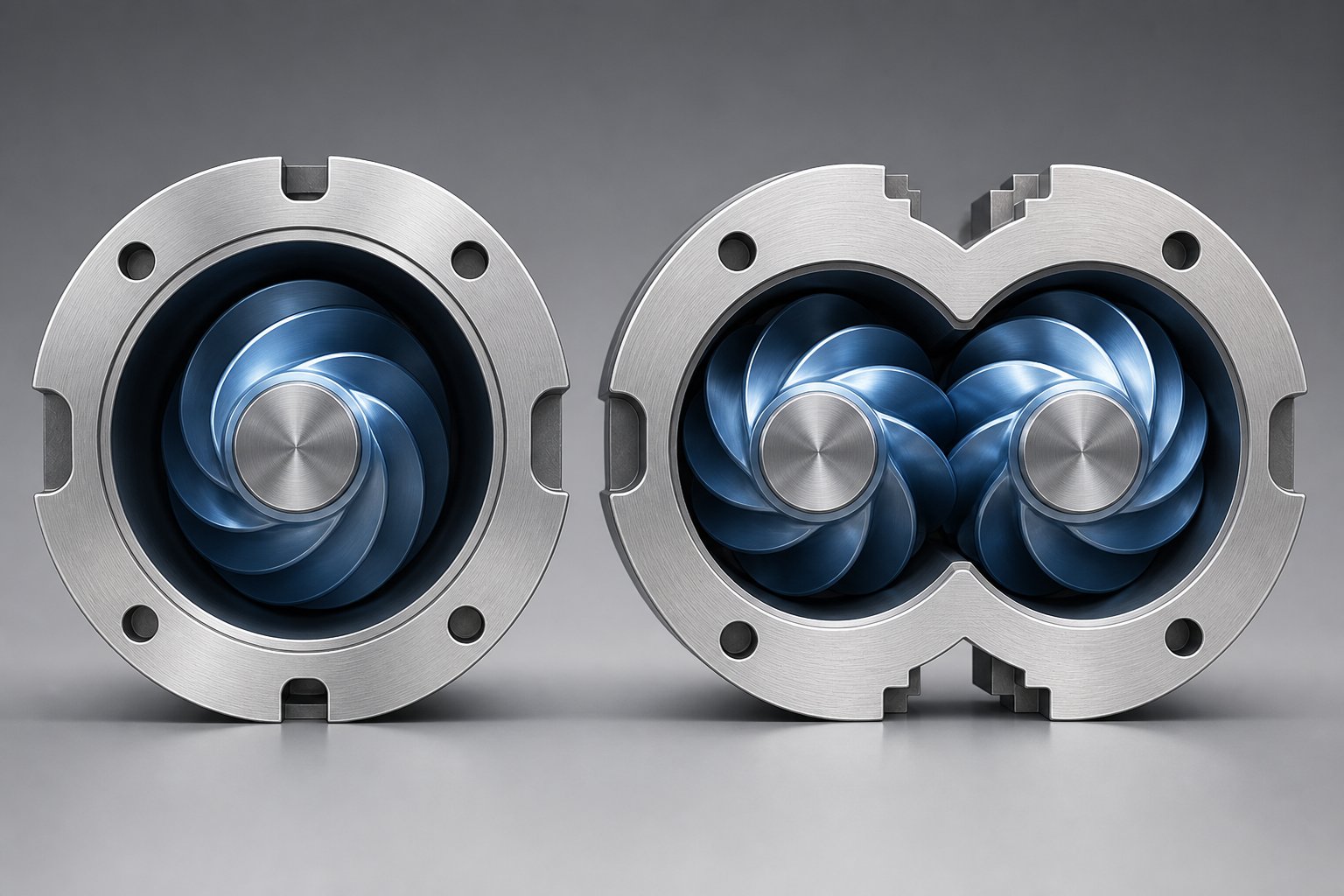
Cut a single-screw barrel in half and you will see a perfectly round bore — one smooth cylinder machined to tight tolerances. Cut a twin-screw barrel the same way and the cross-section reveals something entirely different: a figure-eight profile where two overlapping bores intersect. That geometric distinction is not cosmetic. It fundamentally changes how polymer moves through the machine, how intensely it gets mixed, and how the barrel itself wears over time.
Structural and Geometric Differences Between Single and Twin-Screw Barrels
A single-screw extruder barrel houses one rotating screw inside a cylindrical bore. Material advances because solid pellets grip the barrel wall harder than they grip the screw root — a mechanism called frictional drag flow. The screw channel acts like a conveyor: deep flights in the feed zone accept solid pellets, a compression zone squeezes and melts them, and a shallow metering zone pumps uniform melt toward the die. The bore itself is straightforward to machine, typically held to a surface roughness around Ra 0.4 µm with straightness tolerances near 0.015 mm across the full working length.
Twin-screw barrels operate on a completely different principle. The figure-eight bore geometry allows two intermeshing screws to transfer material between each other repeatedly. Instead of relying on friction, the screws physically push polymer forward through positive displacement — meaning even low-friction feedstocks like fine powders, flakes, and irregular regrind convey reliably. This is why twin-screw configurations dominate applications where the feedstock is not a uniform pellet.
Bore tolerances and flight clearances tell a revealing story about wear behavior in each configuration. In a single-screw barrel, the critical clearance sits between the screw flight outer diameter and the bore wall — typically a few tenths of a millimeter on new equipment. Wear tends to be radial and relatively uniform along the bore, concentrated in the compression zone where pressure peaks. Twin-screw barrels face a more complex picture. Wear concentrates at the intersection of the two bores — the so-called "apex" region — and along the kneading block zones where shear forces are highest. Because twin-screw systems involve two rotating elements in close proximity, even slight bore wear can alter the intermeshing clearance and degrade mixing performance faster than equivalent wear in a single-screw setup.
Construction philosophy diverges as well. Most single-screw barrels are manufactured as one-piece units — a single length of steel, bored, honed, and heat-treated as one component. This approach offers excellent rigidity and alignment, though it means the entire barrel must be replaced when one section wears beyond tolerance. Twin-screw barrels, particularly parallel co-rotating designs used in compounding, typically use modular segmented construction. Individual barrel sections bolt together along the machine length, and each section can be independently replaced, reconfigured, or upgraded with different liner alloys. That modularity adds cost and introduces potential alignment challenges at the joints, but it delivers flexibility that a monolithic barrel cannot match.
Choosing Between Configurations Based on Process Requirements
When should you reach for each type? The decision hinges on two questions: what form does your feedstock arrive in, and what does the melt need to become before it reaches the die?
Single-screw barrels earn their place when the polymer arrives as pre-compounded, uniform pellets and the process demands clean melting at steady pressure — think HDPE pipe, LDPE blown film, ABS sheet, or cable sheathing. You are not asking the machine to mix, disperse, or devolatilize. You are asking it to melt and pump. A single-screw barrel does that reliably, at lower capital cost, with simpler maintenance and easier operator training.
Twin-screw barrels become necessary when the melt must be transformed, not merely melted. Compounding masterbatch with fine pigment dispersions, reinforcing nylon with glass fiber, performing reactive extrusion, removing volatiles under vacuum, or processing rigid PVC from dry powder blend — these tasks demand the intensive mixing, precise residence-time control, and positive displacement conveying that only an intermeshing twin-screw barrel provides. The tradeoff is real: twin-screw barrels carry a 3-5x cost premium over comparable single-screw units and require deeper process knowledge to operate effectively.
| Feature | Single-Screw Barrel | Twin-Screw Barrel |
|---|---|---|
| Bore Geometry | Single round cylindrical bore | Figure-eight (two intersecting bores) |
| Conveying Mechanism | Frictional drag flow — pellets must grip the barrel wall | Positive displacement — screws mechanically push material forward |
| Mixing Intensity | Limited; mixing elements (e.g., Maddock) help but reduce output | Excellent dispersive and distributive mixing via kneading blocks |
| Feedstock Flexibility | Best with uniform pellets; struggles with powders and flakes | Handles pellets, powders, flakes, fibers, and irregular regrind |
| Typical Applications | Pipe, film, sheet, cable sheathing, blow molding | Compounding, masterbatch, glass-fiber reinforcement, reactive extrusion, PVC, devolatilization |
| Barrel Wear Pattern | Radial wear, fairly uniform; concentrated in compression zone | Wear at bore apex and kneading zones; clearance-sensitive |
| Construction Style | One-piece (monolithic) — simple, rigid, full replacement when worn | Modular/segmented — individual sections replaceable and reconfigurable |
| Relative Barrel Cost | 1x (baseline) | 2-5x depending on configuration (conical vs. parallel) |
| Maintenance Complexity | Low — pull screw, measure, reinstall | Higher — modular elements, multiple wear points, alignment checks |
A pattern worth noting: the most expensive mistake in barrel selection is not choosing between single and twin-screw — it is paying for mixing capability you never use, or starving a compounding process with a barrel architecture that cannot deliver it. Either way, the costs show up in rejects, downtime, and premature replacements long before anyone traces them back to the barrel specification.
Barrel geometry sets the boundaries of what is processable. But within those boundaries, another specification — the length-to-diameter ratio — determines how much processing work the barrel can actually accomplish along its length.
L/D Ratio and Feed Zone Configuration Explained
A barrel's bore diameter tells you what size material stream it handles. Its length tells you how much processing work it can perform. The ratio between those two dimensions — length divided by diameter, or L/D — is one of the most consequential numbers on any barrel extruder specification sheet. Yet it is also one of the most frequently copied from a previous purchase order without re-evaluation.
What L/D Ratio Means for Processing Capability
The extruder barrel length to diameter ratio, expressed as a simple number like 24:1 or 36:1, represents how many bore diameters fit along the barrel's working length. A 90 mm barrel with a 36:1 ratio, for example, measures 3,240 mm from the feed opening to the discharge flange. That length is not arbitrary — it dictates how many functional zones (feeding, compression, metering, venting, mixing) the screw designer can fit inside the barrel, and how much time the polymer spends exposed to heat and shear.
In the early 1960s, a 20:1 L/D was typical and 24:1 was considered long. Today, 30:1 to 36:1 has become the industry standard, with some machines exceeding 40:1 for specialized tasks like double venting or high-speed compounding. The shift happened because processors demanded higher output rates and better melt homogeneity — and both require more barrel length to achieve.
Here is how L/D ratio affects melt quality and throughput in practice: since the feed section stays approximately the same length regardless of overall L/D, every additional unit of length goes toward melting, mixing, and pressure development. Deeper screw channels can push more material per revolution, but they also need more barrel length to complete the melting process and build discharge pressure. That tradeoff explains why simply "going longer" is not always better.
A barrel that is too long for the application creates problems that are easy to miss until they show up in the product. As extrusion specialist Jim Frankland notes, an excessively long screw can actually limit output by generating melt temperatures high enough to cause polymer breakdown, color shift, additive degradation, and plate-out. Conversely, a barrel that is too short starves the melt of residence time — producing undermixed output, unmelted gels, and pressure instability at the die.
The following list matches common L/D ratios to their typical application categories:
- 24:1 — General-purpose single-screw extrusion of easy-melting polymers (LDPE, LLDPE blown film, simple profile extrusion). Sufficient for low-head-pressure processes with pre-compounded pellets.
- 28:1 to 30:1 — The minimum practical ratio for two-stage vented screws, which consume 4-6 diameters in the vent zone alone. Also the best L/D ratio for polyolefin extrusion lines requiring moderate output rates and good melt consistency.
- 32:1 to 36:1 — The current workhorse range for engineering plastics (nylon, PC, PBT), moderately filled compounds, and processes demanding tight melt-temperature control. Twin-screw compounding lines for glass-fiber reinforcement and filler masterbatch commonly land here.
- 36:1 to 40:1+ — Reserved for high-output compounding, reactive extrusion, devolatilization of moisture-sensitive resins, and heavily filled systems that demand extended residence time for thorough wetting and dispersion.
Selecting the wrong L/D ratio is not a minor inconvenience — it is a structural limitation baked into the machine. You cannot screw-design your way out of a barrel that is fundamentally too short or too long for the polymer and process at hand.
Feed Zone Design and Its Impact on Solids Conveying
Every pellet's journey through the barrel begins at the feed zone, and what happens in those first few diameters of barrel length sets the ceiling for everything downstream. If solids conveying falters here, no amount of thermal tuning or screw optimization further along the barrel can recover the lost output.
The extruder feed zone geometry and solids conveying efficiency are tightly linked. Pellets or powder drop from the hopper through a feed throat — an opening machined into the barrel's upstream end — and land in the deep screw channels of the feed section. The screw drags them forward, but only if the friction coefficient between the pellets and the barrel wall exceeds the friction between the pellets and the screw root. That friction differential is the engine of solids conveying in single-screw systems.
Feed throat cooling plays a critical role in maintaining this friction balance. As Graham Engineering details, the feed section typically includes a cast housing with internal cooling passages that keep the throat temperature in the 32-49 °C (90-120 °F) range. This thermal barrier prevents heat from migrating backward from the hot barrel zones into the feed area. Without adequate cooling, pellets begin to soften and stick to the throat walls — a condition called bridging — which restricts or completely blocks material flow. Low-melting-point polymers like EVA and certain polyolefins are especially vulnerable.
Feed-section geometry also matters. Channel depth in the feed zone determines the volume of solid material the screw can accept per revolution — essentially the machine's intake capacity. A deeper feed channel grabs more material but demands a longer compression zone to melt it completely. The feed zone's axial length, typically 4 to 8 diameters, must be long enough for the solid plug to develop sufficient pressure against the barrel wall before it transitions into the compression zone.
Getting feed zone design right is a balancing act between intake volume, cooling capacity, and friction management. Misjudge any of these, and the result is the same: output instability that no downstream adjustment can fully compensate. That balancing act becomes even more interesting when comparing the two fundamental approaches to feed-section engineering — smooth bore and grooved feed designs — each of which changes the conveying physics entirely.
Smooth Bore vs Grooved Feed Barrel Designs
The previous section ended with a critical question: how do you get solid pellets to move forward reliably in the first few diameters of the barrel? The answer depends entirely on whether the feed section uses a smooth bore or machined grooves — and that choice reshapes the conveying physics, screw design requirements, and performance envelope of the entire barrel extruder.
How Smooth Bore Barrels Convey Polymer Through Friction
In a smooth bore barrel, solids conveying runs on one principle: frictional drag. Pellets entering the feed zone must grip the barrel wall harder than they grip the screw root. When that friction differential exists, the barrel's stationary surface anchors the solid plug while the rotating screw pushes it forward — much like a nut advancing along a rotating bolt. The mechanism works, but it is inherently sensitive to variables that shift friction coefficients.
Temperature is the biggest wildcard. If the feed zone runs too warm, pellet surfaces begin to soften and smear against the barrel wall, reducing the barrel-side friction that drives conveying. Resin type matters just as much — slippery polymers with external lubricant packages or high levels of slip additive can starve a smooth bore machine of forward force. And because the metering zone at the discharge end governs pressure buildup, smooth bore systems show a pronounced counter-pressure dependence: as die resistance increases, throughput drops. Researchers at the University of Stuttgart confirmed this directly, finding that smooth barrel mass throughput results from isolated solids conveying experiments were not transferable to full extrusion setups because the counter-pressure effect was so significant.
That sensitivity is not always a disadvantage. Smooth bore barrels excel at versatility. Because conveying force can be tuned through temperature adjustments and screw geometry changes, a smooth-feed extruder handles a wider range of polymers — including high-melt-temperature materials like nylon, PET, and polycarbonate — without requiring hardware changes. When production schedules call for frequent resin switches, smooth bore setups demand less mechanical reconfiguration.
Grooved Feed Barrel Mechanics and Screw Design Implications
Grooved feed barrels take an entirely different approach to solids conveying. Instead of depending on friction alone, machined grooves — typically eight to eighteen of them evenly distributed around the bore — physically interlock with the solid pellets in the feed zone. Pellets wedge into the grooves and cannot rotate with the screw. This mechanical locking creates a positive-displacement effect in the feed section, generating high conveying pressure regardless of the polymer's surface friction characteristics.
The grooves are typically 0.15-0.3 inches wide, starting at a depth of 0.12-0.37 inches near the feed opening and tapering to zero over three to four bore diameters downstream. Intensive water cooling surrounds the grooved section to prevent resin from melting inside the grooves — a critical detail, because molten polymer filling the grooves eliminates the mechanical locking effect entirely. The grooves run parallel to the screw axis in most modern designs, though helical groove configurations also exist and research shows the throughput difference between axial and helical grooves diminishes at higher screw speeds.
Here is where things get interesting for screw designers. Because the grooved feed zone generates so much conveying force, it — not the metering section — controls throughput. This flips the conventional design hierarchy of a smooth bore system on its head. Grooved barrel screw design requirements demand shallower, more uniform feed channels. On a 3.5-inch screw, feed channel depth with a grooved barrel runs 0.25-0.4 inches — roughly half the 0.6-0.7 inch depth typical with smooth bore designs. Those shallow channels keep the solid bed height short, maintain high forward force in the grooves, and build enough pressure to achieve adequate compression entering the heated barrel sections.
The grooved feed barrel advantages for polyolefins are substantial and well documented. In case studies comparing a 3.5-inch (90 mm) grooved feed extruder against a 4.5-inch (114 mm) smooth bore machine processing high-viscosity HDPE at 1,100 lb/hr, Davis-Standard found the grooved feed configuration achieved lower melt temperatures and reduced power consumption, translating to energy savings of 268,000 to 388,000 kWh per year — or $26,800 to $38,800 in annual operating cost reductions. The smaller-diameter grooved feed machine matched the output of a larger smooth bore unit while consuming less energy. That is how a grooved feed zone increases extruder output: by decoupling conveying efficiency from friction, allowing higher throughput per revolution at lower screw speeds and lower melt temperatures.
The tradeoff? Pressures at the end of the grooved section can reach 15,000-20,000 psi, with equipment typically rated to handle up to 30,000 psi as a safety margin. This means grooved feed extruders demand significantly more robust thrust bearings and larger gearboxes than smooth bore machines of similar diameter. Startup torque is also higher, requiring drive systems sized for worst-case conditions rather than steady-state operation.
| Feature | Smooth Bore Barrel | Grooved Feed Barrel |
|---|---|---|
| Conveying Mechanism | Frictional drag between pellets and barrel wall | Mechanical interlocking of pellets in machined grooves |
| Output Stability | Sensitive to die back-pressure; output drops as die resistance increases | Largely independent of die pressure — feed zone controls throughput |
| Temperature Sensitivity | High — overheated feed zone reduces friction and starves conveying | Requires intensive cooling to prevent melting in grooves, but conveying force is friction-independent |
| Screw Design Requirements | Conventional decreasing-depth compression screw; metering zone governs output | Shallow, more uniform feed channels (roughly half the depth of smooth bore screws); feed zone governs output |
| Ideal Polymer Types | Broad range — nylon, PET, PC, fluoropolymers, frequent resin changes | Polyolefins (HDPE, LLDPE, PP); high-viscosity PE for pipe, blown film, blow molding |
| Thrust-Bearing Demands | Standard — feed zone pressures typically under 5,000 psi | Heavy-duty — feed zone pressures can reach 15,000-20,000 psi; equipment rated to 30,000 psi |
| Output per RPM | Baseline | 20-40% higher than equivalent-diameter smooth bore machine |
| Regrind Tolerance | Good — deep feed channels accommodate variable particle size | Limited — particle size affects groove performance; requires controlled feed |
One practical detail that often gets overlooked: grooved feed extruders perform best with dedicated, single-resin operations running pre-colored polyolefins at high output rates. Processors who need to switch between polymers frequently, handle variable regrind percentages, or run high-melt-temperature engineering resins will generally find smooth bore barrels more forgiving and cost-effective. It is not that one design is universally superior — it is that each solves a different set of constraints.
Regardless of whether the feed section uses grooves or a smooth bore, every barrel faces a common enemy over time: wear. And the type of material flowing through the bore, combined with the pressures and temperatures involved, determines exactly how that barrel will deteriorate — and how quickly.
Barrel Wear Mechanisms and How to Prevent Them
A barrel does not fail all at once. It degrades — slowly, invisibly, millimeter by millimeter — until the day output drops, melt quality shifts, or a bore measurement reveals dimensions well beyond tolerance. By then, thousands of dollars in scrap, energy waste, and unplanned downtime have already accumulated. The root cause almost always traces back to one of three wear mechanisms operating inside the bore. Knowing which one is attacking your barrel changes everything: the liner you specify, the maintenance interval you set, and the budget you plan for replacements.
Abrasive, Corrosive, and Adhesive Wear Mechanisms
Think of the inside of a working barrel as a battlefield with three different kinds of attackers. Each leaves a distinct signature on the bore surface, each responds to different countermeasures, and each demands a different metallurgical defense. Misidentifying the dominant mechanism is one of the most expensive diagnostic errors in plastics processing — because it leads directly to specifying the wrong barrel liner.
Abrasive wear is the most common form of barrel degradation, and it behaves exactly the way sandpaper behaves against a wooden surface. Every rotation of the screw pushes filler particles — glass fibers, calcium carbonate, talc, titanium dioxide, wollastonite, or contaminants in recycled feedstock — against the bore wall under pressure. These hard particles act as cutting tools, gradually removing metal from the barrel's inner surface. The damage concentrates in the transition and metering zones where melt pressure forces particles hardest against the wall. Processing compounds with glass-fiber loadings above 30% accelerates this wear dramatically, sometimes reducing barrel life from years to months.
Corrosive wear operates through chemistry rather than mechanics. When certain polymers degrade at processing temperatures, they release acidic byproducts that chemically attack metal surfaces. PVC is the most notorious offender — thermal decomposition generates hydrochloric acid (HCl) that eats into unprotected steel. Fluoropolymers like PVDF and PTFE release hydrofluoric acid (HF), which is even more aggressive. Halogenated flame-retardant additives and certain engineering resins with moisture-sensitive chemistries compound the problem. Unlike abrasion, corrosive wear does not require high filler loads or extreme pressures. It simply requires time, temperature, and the wrong barrel metallurgy.
Adhesive wear is the least understood of the three, yet it produces the most dramatic damage. It occurs when the screw flight tips physically contact the barrel wall without a lubricating polymer film between them. At those contact points, microscopic welds form under pressure and then tear apart as the screw rotates — transferring metal from one surface to the other. This galling effect happens most often during cold starts before a full melt film develops, during dry running when the feed starves, or when worn bearings or gearbox issues allow the screw to deflect and contact the bore. The result is rapid, localized destruction that can render a barrel unusable in a fraction of the time abrasive or corrosive wear would take.
Here is the critical complication: these mechanisms rarely act alone. A barrel processing glass-filled PVC faces abrasion from the filler particles and corrosion from HCl off-gassing simultaneously. The corrosion roughens the bore surface, creating anchor points where abrasive particles dig in more aggressively — a synergistic combination that accelerates damage far beyond what either mechanism would cause independently.
Visual Indicators and Measurement-Based Wear Detection
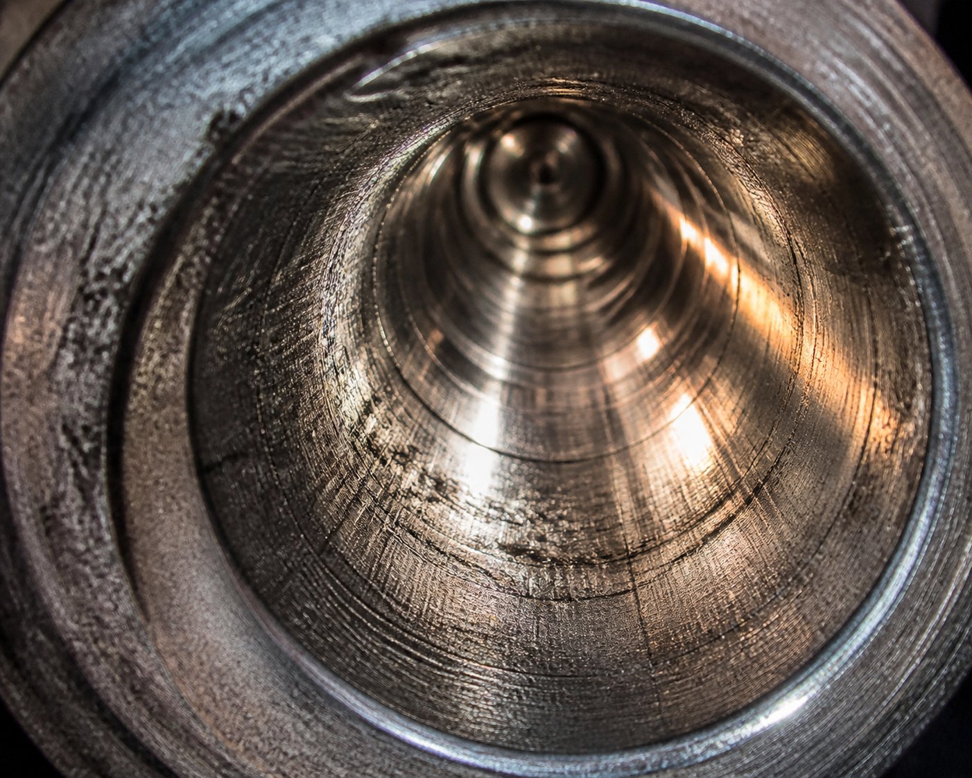
Knowing how to detect barrel bore wear in extrusion starts with understanding what each wear type looks like — both visually and dimensionally. Pull the screw, purge the barrel thoroughly, and examine the bore under strong lighting or with a bore scope. What you see tells you what is happening inside your process.
- Abrasive wear indicators: The bore diameter increases gradually and uniformly, particularly through the compression and metering zones. The surface appears smooth, sometimes almost polished, with original machining marks worn away. Bore gauge measurements reveal consistent enlargement without localized pitting or roughness. A general industry guideline flags total diametrical clearance beyond 0.8-1.0% of the nominal diameter as significant wear.
- Corrosive wear indicators: Instead of smooth enlargement, you will find pitting, dimpled surfaces, and a rough, chemically etched texture — as if the metal has been eaten from the inside rather than scraped away. This damage typically concentrates in the metering zone and die adapter area where melt temperatures peak. Discoloration of the bore surface, sometimes with a greenish or darkened appearance, often accompanies the pitting.
- Adhesive wear indicators: Look for scoring lines running along the barrel's axial length, smeared metal deposits, and galled patches on the bore wall. These marks frequently appear in the feed zone — before a full melt film develops — or wherever the screw has deflected and contacted the bore directly. The damage pattern is localized and irregular, distinctly different from the uniform enlargement of abrasive wear or the chemical pitting of corrosive wear.
Dimensional measurement adds objectivity to the visual assessment. Using a telescoping bore gauge paired with an outside micrometer — or a dedicated dial bore gauge — take readings at intervals of 4 to 6 inches along the barrel's entire length, at two perpendicular orientations per location. This creates a wear profile that reveals not just how much the bore has enlarged, but where the degradation concentrates. Uniform enlargement with a polished surface points to abrasion. Localized pitting without significant diameter change points to corrosion. Scoring concentrated near the feed zone or at discrete points along the length points to adhesive contact.
Tracking these measurements over multiple inspection cycles is where the real value emerges. A single data point tells you the current state. A trend line tells you how fast the barrel is deteriorating and when it will reach its tolerance limit — giving you the ability to schedule replacements during planned downtime rather than reacting to production failures.
Prevention Strategies That Extend Barrel Life
Understanding the dominant wear mechanism does more than satisfy engineering curiosity — it determines the correct barrel metallurgy and liner specification. Apply the wrong prevention strategy and you waste money on protection that does not address the actual threat.
- Preventing abrasive wear: A bimetallic barrel liner for abrasive wear resistance is the most effective defense. Iron-boron alloy liners (58-65 HRC) handle moderate filler loads under 30%. For heavily glass-fiber-reinforced compounds, tungsten carbide composite liners — with embedded carbide particles exceeding 70 HRC — provide several times the service life of standard liners. Equally important: maintain proper screw-to-barrel clearance and inspect at intervals driven by your actual wear rate data, not arbitrary calendar schedules.
- Preventing corrosive wear in PVC extruder barrels and similar applications: Nickel-based alloy linings (Ni-Cr or Ni-Mo compositions) form a passive oxide layer that resists acid penetration from HCl and HF off-gassing. Hardness matters far less here than chemical resistance — a nickel-based liner at 45-60 HRC outperforms a harder iron-based liner that corrodes in months. Operational discipline is equally critical: never leave corrosive resin sitting idle in a hot barrel, purge properly before every shutdown, and avoid temperature excursions that accelerate polymer degradation.
- Preventing adhesive wear: This is fundamentally a mechanical and operational problem, not a materials problem. Verify proper warm-up soak times before introducing feed material — cold starts without adequate barrel temperature are a primary trigger. Eliminate dry running by monitoring feed consistency. Inspect screw alignment, bearing condition, and gearbox health regularly. On the metallurgical side, ensure the barrel liner is at least 5-8 HRC points harder than the screw flight surface, and pair alloys from different families to prevent galling.
For barrels facing combined abrasive and corrosive attack — the reality in many PVC compounding and filled engineering plastics operations — hybrid liners with tungsten carbide particles dispersed in a nickel-based matrix address both mechanisms simultaneously. These dual-purpose liners cost more than single-function alternatives, but they eliminate the forced compromise of choosing protection against only one wear mode.
One final point that experienced maintenance engineers emphasize: barrel metallurgy is necessary but not sufficient. Even the best liner degrades faster than it should if operating parameters drift — temperatures running too high degrade polymer and release more corrosive byproducts, temperatures running too cold increase melt viscosity and mechanical stress, and contaminated feedstock introduces abrasive particles that no liner specification anticipated. Barrel wear prevention is a system-level discipline, not a purchase order.
That system-level thinking extends directly into how the barrel manages heat across its working length. The same thermal zones that control melting and melt quality also influence wear rates, degradation chemistry, and the boundary conditions that either protect or destroy the bore surface.
Thermal Management Across Barrel Heating and Cooling Zones
Every barrel extruder is, at its core, a precisely controlled thermal machine. The wear mechanisms covered earlier are accelerated or restrained by temperature — corrosive byproducts release faster in overheated zones, adhesive contact worsens during cold starts, and melt viscosity swings with every degree of temperature drift. That reality makes thermal management far more than a convenience feature. It is the primary lever operators have for controlling melt quality, output consistency, and product integrity.
Barrel thermal control is the single most influential process variable for melt quality — every zone temperature decision directly affects viscosity, homogeneity, degradation risk, and dimensional stability of the finished product.
How Barrel Zones Control the Melting Process
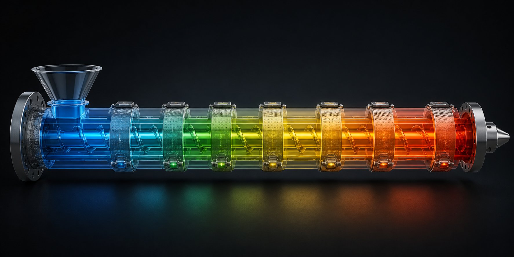
Picture a barrel divided into four to ten independently regulated thermal segments, each with its own heater, temperature sensor, and — in many cases — its own cooling circuit. This extruder barrel heating and cooling zone setup creates a temperature profile that shepherds the polymer through its transformation: from rigid pellet, to partially melted solid bed, to fully homogeneous melt ready for the die.
The feed zone operates differently from every zone downstream. Rather than adding heat, it typically requires active cooling. Typical feed zone temperatures for standard thermoplastics range from 20 °C to 60 °C — well below the polymer's softening point. Why so cold? If pellets begin to melt before they are compressed and conveyed forward, they smear against the barrel wall and bridge across the feed throat, blocking material flow entirely. Grooved feed barrels are especially vulnerable to this, which is why their grooved sections use dedicated water-cooling jackets operating at aggressive flow rates. In some cases, processors deliberately raise feed zone temperatures to 60-95 °C to reduce screw drive torque or increase throughput — but this demands careful monitoring to avoid bridging.
The transition (compression) zones introduce progressively higher temperatures. The goal here is to initiate melting through a combination of frictional (dissipative) heat generated by the screw and conducted heat from the barrel wall. A common rule of thumb sets the first heated zone slightly above the polymer's crystalline melting temperature — high enough to ensure melting begins, but not so high that the motor cannot contribute its share of dissipative energy. Setting this zone too hot actually wastes motor power, because a softer solid bed slips more easily and generates less internal friction.
The metering zone and die zone maintain the final melt temperature — typically matching the resin manufacturer's recommended processing temperature. For semi-crystalline materials, this usually falls 50-75 °C above the melting point. For amorphous resins, roughly 100 °C above the glass transition temperature serves as a practical starting point. An important nuance that experienced operators know well: the set-point temperature displayed on the controller rarely equals the actual melt temperature. The real melt is usually hotter than the barrel wall reading, because the thermocouple sits in the steel — not in the flowing polymer. This gap means that an intentional negative correction to set-points is sometimes necessary to prevent overheating.
Three common barrel temperature profile shapes emerge in practice:
- Rising profile — Temperature increases steadily from the first heated zone to the die. This is the most universally applicable starting point for initial setup.
- Flat profile — A constant temperature across all heated zones, often used with polymers that are sensitive to long thermal gradients or that require uniform shear conditions.
- Humped (peaked) profile — Temperature rises to a peak in the mid-barrel zones, then drops toward the die. This approach can improve melt homogeneity in certain cases by allowing the polymer to relax before final shaping.
Selecting the right profile shape depends on the resin, the screw design, the extruder's wear state, and even ambient shop conditions. A barrel temperature profile effect on melt quality is profound: too-hot mid-zones cause degradation, black specks, and mechanical property loss; too-cold zones leave unmelted gels and produce pressure surges at the die.
Heater Band Selection and Cooling System Design
The hardware that creates and maintains those temperature profiles matters just as much as the set-points themselves. When comparing ceramic vs mica heater bands for extruder barrels, the choice hinges on operating temperature, thermal response, energy efficiency, and physical space constraints.
Mica band heaters are the industry workhorse for general-purpose extrusion. They use NiCr resistance wire wound around a phlogopite mica insulating core, enclosed in a thin stainless steel sheath. Their advantages are compelling: ultra-thin profiles (3-5 mm), minimum inner diameters as small as 25 mm, extremely fast thermal response due to low thermal mass, and significantly lower purchase cost. For processing commodity polymers like ABS, PP, and PE where barrel temperatures stay safely below 300 °C, mica heaters deliver reliable performance. Their limitation is a hard physical ceiling: above 340 °C, the organic binders in the mica sheets begin to carbonize, destroying the dielectric barrier and causing the heater to arc to the barrel. Mica heaters also radiate heat in both directions — inward toward the polymer and outward into the shop — because they lack built-in insulation.
Ceramic band heaters step in where mica cannot. Interlocking steatite ceramic tiles replace the mica insulator, and a 12 mm thick ceramic fiber blanket insulates the outer shell. This construction enables safe operation up to 600 °C at watt densities up to 6 W/cm² — double the thermal capacity of mica. The built-in insulation forces heat inward toward the barrel bore, reducing ambient heat loss and lowering power consumption by 25% to 30% compared to uninsulated mica elements. For processing high-temperature engineering resins like PEEK, nylon, and fluoropolymers — or for 24/7 continuous production lines where energy costs accumulate relentlessly — ceramic is the only viable specification. The tradeoffs are bulk (roughly 12 mm thickness, minimum 60 mm inner diameter) and higher upfront cost, though real-world factory audits show a break-even point within six months under high-load continuous operation.
Cast aluminum heaters occupy a third niche. Molten aluminum is cast directly around the resistance element and machined to fit the barrel's exact outer diameter. This approach delivers exceptional thermal uniformity and eliminates air gaps — but at higher cost and with limited ability to be transferred between barrels of different dimensions. Cast aluminum heaters are most common on large-diameter barrels and extrusion lines where zone-to-zone temperature uniformity is critical for the final product.
On the cooling side, three systems handle heat removal when barrel temperatures need to come down — either to prevent overheating from shear-generated heat or to maintain tight temperature control in sensitive zones:
- Air-cooled fins and blowers — The simplest and most common approach. Fans or blowers direct ambient air over finned barrel surfaces or heater band gaps. Response is relatively slow, and cooling capacity is limited by shop air temperature — a real concern in summer months or tropical climates.
- Water-cooled channels — Drilled or cast passages within the barrel wall circulate coolant for rapid, high-capacity heat removal. Essential in the feed zone of grooved barrels and in high-speed extrusion where viscous dissipation generates more heat than the polymer can absorb. Water cooling offers precise, fast response but introduces maintenance concerns: scale buildup, corrosion in the cooling passages, and the risk of water leaks near electrical connections.
- Combination systems — Many modern barrel extruders use water cooling in the feed section and air cooling across the remaining heated zones. This hybrid approach balances the aggressive cooling needed to prevent bridging with the gentler, lower-maintenance cooling sufficient for mid-barrel temperature trimming.
Active cooling becomes especially important with shear-sensitive materials like PVC, PVDF, and certain TPEs, where even modest temperature overshoots trigger degradation. It is equally critical in high-speed processing, where the screw's mechanical energy input can exceed the barrel's ability to shed heat passively. In these scenarios, relying on heater bands alone — simply turning them off and waiting for the barrel to cool — is far too slow to prevent temperature excursions.
Vented Barrel Configurations for Degassing and Volatile Removal
Not every barrel runs as a sealed cylinder from feed to die. A vented extruder barrel for moisture-sensitive polymers incorporates one or more open ports along its length, allowing trapped air, surface moisture, volatile monomers, and degradation byproducts to escape the melt stream before the polymer reaches the die.
When is venting necessary? Any time the polymer carries volatiles that would otherwise manifest as bubbles, splay marks, or voids in the finished product. Nylon (PA6, PA66) absorbs atmospheric moisture rapidly and requires either pre-drying or vacuum-assisted barrel venting to remove moisture and monomer residues during processing. Polycarbonate, PET, and other hygroscopic resins face similar challenges. Recycled feedstock — which often carries surface contamination, printing inks, and residual moisture — benefits enormously from vented barrel configurations that would be unnecessary with virgin material.
Vent port positioning directly affects degassing efficiency. The vent is typically located in a decompression zone where the screw channel deepens abruptly, dropping melt pressure to near zero. This pressure relief allows volatiles to flash out of the melt and escape through the vent port, which may operate at atmospheric pressure (atmospheric venting) or under vacuum (vacuum venting) for more aggressive volatile removal. On a two-stage vented screw, the vent port usually sits 60-70% of the way along the barrel length — after the first-stage metering section completes initial melting and before the second-stage compression zone rebuilds pressure for die delivery.
Vacuum-assisted venting, using liquid ring vacuum pumps or similar systems, pulls volatiles out of the melt more aggressively than atmospheric venting alone. This is standard practice for PET recycling, nylon compounding, and any process where residual volatile levels must meet strict specifications. The vacuum level, vent port geometry, and screw channel depth in the decompression zone must all be coordinated — too much vacuum without adequate decompression can pull molten polymer up through the vent (a condition called "vent flow"), creating a mess and interrupting production.
Vented barrels add cost, complexity, and barrel length — a two-stage vented screw typically requires a minimum L/D of 28:1 to 30:1, consuming 4-6 diameters for the decompression and vent zone alone. But for moisture-sensitive polymers and volatile-laden feedstocks, the alternative — pre-drying systems, product defects, or post-extrusion quality losses — is almost always more expensive than the vented barrel itself.
Thermal management and venting address how energy and volatiles move through the barrel. The next critical question is what the barrel itself is made of — because the metallurgy of the bore surface determines whether the thermal zones, pressures, and polymer chemistries described here gradually destroy the barrel or coexist with it for years.
Barrel Material Selection and Polymer Compatibility
Thermal zones keep the melt on target. Vent ports pull volatiles out of the stream. But the bore surface itself — the metal that actually contacts the polymer melt under pressure, hour after hour — determines whether that carefully tuned barrel lasts five years or five months. Choosing the wrong barrel material for your polymer is like putting summer tires on an ice road: everything looks fine at the start, and the failure cost is enormous.
Common Barrel Materials and Their Protective Properties
Barrel construction follows a layered logic. The outer shell provides structural strength — the ability to contain internal pressures that routinely exceed 300 bar without deformation. The inner bore surface, however, carries a completely different burden: resisting chemical attack, abrasive erosion, and metal-to-metal contact while maintaining the dimensional precision that keeps screw-to-barrel clearance within specification. These two demands rarely call for the same alloy, which is why modern barrels separate the structural role from the protective role through liners, coatings, and surface treatments.
Nitrided steel (38CrMoAlA or equivalent) represents the baseline specification for general-purpose processing. Gas nitriding diffuses nitrogen into the steel surface at controlled temperatures, forming a hard nitride case layer — typically 0.3-0.7 mm deep — over a tough, ductile core. The result is a barrel bore with surface hardness in the 65-72 HRA range, adequate wear resistance for unfilled commodity resins, and a purchase price that makes it the most economical option in the market. If you are running clean PE, PP, PS, or ABS without mineral fillers or glass reinforcement, a nitrided steel barrel delivers a solid balance of performance and cost. Its limitation becomes apparent the moment abrasive or corrosive materials enter the picture — the nitride layer is thin, and once it wears through, the softer substrate underneath erodes rapidly.
Bimetallic linings (iron-boron alloys) address that limitation through centrifugal casting. During manufacturing, the barrel is spun at high speed while molten liner alloy is poured inside, forcing the wear-resistant material outward against the bore wall under centrifugal force. The result is a metallurgical bond between a structural outer shell and a hard inner liner — typically 1.5-3.0 mm thick — with hardness values reaching 58-65 HRC. Iron-boron-based liners embed hard boride particles in a tough matrix, creating a surface that resists abrasive erosion far more effectively than nitriding alone. This is the standard specification for processing glass-fiber-reinforced compounds, mineral-filled masterbatch, and recycled streams carrying contaminants. A bimetallic barrel liner for abrasive wear resistance can deliver three to five times the service life of a nitrided bore under identical processing conditions.
Nickel-based alloy linings shift the defense from mechanical hardness to chemical resistance. Alloys in the Hastelloy family — nickel-chromium-molybdenum compositions — form a passive oxide layer that resists penetration by hydrochloric acid from PVC processing and hydrofluoric acid from fluoropolymer degradation. Surface hardness runs lower (45-60 HRC) compared to iron-boron liners, but that matters little when the primary threat is corrosive rather than abrasive. Extruder barrel liner compatibility with PVC processing depends almost entirely on selecting a nickel-based or nickel-chromium liner — standard nitrided steel corrodes visibly within weeks under aggressive PVC conditions, and even iron-boron bimetallic liners, despite their hardness, can succumb to acid attack because of their high iron matrix content.
Tungsten-carbide-based linings sit at the top of the performance (and price) ladder. By dispersing tungsten carbide particles within a nickel or cobalt binder matrix, these liners achieve hardness values exceeding 1,100-1,400 HV — dramatically outperforming every other option in pure abrasion resistance. They are specified for the most punishing applications: high-percentage glass-fiber compounds (40%+), ceramic-loaded masterbatches, and processing environments where both abrasive and corrosive wear attack simultaneously. The cost premium is significant — often two to four times a standard bimetallic liner — but in applications where a conventional liner lasts six months, a tungsten-carbide bore can run for several years before requiring replacement.
Matching Barrel Metallurgy to Polymer and Filler Type
Knowing what each liner does in isolation is only half the picture. The real decision comes when you match a specific polymer-and-filler combination to the barrel material that will deliver the lowest total cost of ownership for that exact application. The following table provides a practical compatibility framework, mapping common processing scenarios to their recommended barrel specifications.
| Polymer / Filler Category | Recommended Barrel Material / Liner | Expected Dominant Wear Mode | Relative Cost Tier |
|---|---|---|---|
| Unfilled commodity resins (LDPE, HDPE, PP, PS, ABS) | Nitrided steel (38CrMoAlA) | Mild abrasive wear from pellet friction; slow, uniform bore enlargement | $ (Baseline) |
| Glass-fiber-reinforced engineering plastics (PA6-GF30, PA66-GF50, PBT-GF) | Bimetallic iron-boron alloy liner or tungsten-carbide composite liner | Severe abrasive wear — glass fibers erode bore at 5-10x the rate of unfilled resin | $$$ - $$$$ |
| Mineral-filled compounds (CaCO3, talc, BaSO4 in PP or PE) | Bimetallic iron-boron alloy liner | Moderate abrasive wear; less aggressive than glass fiber but accelerated vs. unfilled | $$ |
| Rigid and flexible PVC | Nickel-based alloy liner (Ni-Cr or Ni-Mo composition) | Corrosive wear from HCl release during thermal degradation | $$$ |
| Fluoropolymers (PVDF, FEP, PTFE) | Nickel-based alloy liner (Hastelloy-type) or specialized high-nickel bimetallic | Corrosive wear from HF acid; extremely aggressive chemical attack | $$$$ |
| Recycled-stream materials with contaminants (post-consumer regrind, mixed-stream reclaim) | Bimetallic iron-boron liner; tungsten-carbide composite for heavily contaminated streams | Combined abrasive wear (metal fragments, grit, mineral contaminants) and mild corrosive wear (degraded additives, inks) | $$ - $$$ |
Notice a pattern? The best barrel material for glass fiber reinforced plastics is never the cheapest option on the purchase order. And that is exactly where the most expensive procurement mistakes happen. A plant running 30% glass-filled nylon through a nitrided steel barrel — because it saved $4,000 on the initial purchase — can burn through that barrel in as little as 4,000 operating hours. The bimetallic alternative, costing perhaps four times more upfront, can last 15,000-20,000 hours under the same conditions. Factor in the downtime for each barrel change, the labor cost of a screw pull and reinstallation, the scrap produced during restart, and the throughput lost during unplanned shutdowns — and the "cheap" barrel becomes the most expensive decision on the production floor.
This cost dynamic plays out even more starkly when comparing nitrided steel vs nickel alloy extruder barrel specifications for PVC processing. A nitrided bore costs less, installs identically, and looks the same on paper. But hydrochloric acid released during PVC degradation penetrates the thin nitride layer, attacks the iron-rich substrate, and produces surface pitting that accelerates mechanical wear. Within months, screw-to-barrel clearance opens, output drops, and operators begin compensating with higher RPM and temperature adjustments — the same creeping inefficiency spiral that industry experts identify as the "point of diminishing returns." The nickel-alloy liner resists that chemical attack entirely, maintaining bore integrity and process stability for years rather than months.
A final consideration that experienced engineers keep front of mind: barrel metallurgy is not a standalone decision. It must be compatible with the screw's surface treatment. Running a tungsten-carbide-lined barrel against a soft nitrided screw creates a hardness mismatch that accelerates screw flight wear. Conversely, an ultra-hard screw flight paired with a softer barrel liner concentrates wear on the more expensive component. The ideal pairing places the harder surface on the replaceable component — typically the screw flight tips — while the barrel liner provides just enough hardness to resist the polymer environment without becoming the abrasive aggressor against the screw.
Selecting the right metallurgy protects the barrel from the polymer. But even perfectly matched materials degrade over time — and catching that degradation early, through disciplined measurement and inspection, is what separates planned maintenance from emergency shutdowns.
Maintenance Schedules and Barrel Wear Monitoring
Metallurgy protects. Operating parameters preserve. But neither eliminates wear entirely. Every barrel extruder is a consumable component on a slow countdown — and the plants that track that countdown methodically spend far less on replacements, scrap, and emergency downtime than those that wait for symptoms to become crises. Yet surprisingly few processors maintain a formal extruder barrel bore measurement and inspection schedule. The result? Barrels run well past their useful life, quietly bleeding output and quality until a catastrophic failure forces action at the worst possible moment.
A structured maintenance framework changes that equation entirely. It replaces guesswork with data, reactive scrambles with planned shutdowns, and budget surprises with predictable cost curves.
Scheduled Inspection Protocols and Bore Measurement Methods
Imagine two identical extruders running the same glass-filled nylon compound on the same production schedule. Plant A measures barrel bore dimensions every 2,000 operating hours and logs the data in a tracking spreadsheet. Plant B waits until operators notice output dropping or melt quality shifting — then pulls the screw for the first time in 18 months. Plant A catches a wear trend at 0.15 mm of diametrical growth and schedules a replacement during its next planned shutdown. Plant B discovers 0.40 mm of enlargement during an emergency teardown triggered by a customer quality complaint. Same barrel, same polymer — completely different maintenance cost outcomes.
The following step-by-step barrel inspection procedure provides a practical framework that maintenance teams can adopt immediately:
- Schedule the inspection based on operating hours, not calendar time. For unfilled commodity resins, inspect every 4,000-5,000 hours. For glass-fiber-reinforced or mineral-filled compounds, shorten that interval to 1,500-2,500 hours. Corrosive polymers like PVC and fluoropolymers warrant inspection every 1,000-2,000 hours during the first year, then adjust intervals based on observed wear rates.
- Pull the screw and purge the barrel thoroughly. Remove all residual polymer from the bore using brass scrapers or copper gauze — never steel wire brushes, which damage the bore surface and create false wear indications. Dry ice blasting or chemical purge compounds help remove stubborn buildup without scratching.
- Measure the bore diameter at regular intervals along the full barrel length. Take readings every 4 to 6 inches (100-150 mm), using two perpendicular orientations at each location to detect ovality. A telescoping gauge paired with an outside micrometer is the traditional method — the gauge's spring-loaded plungers expand to contact the bore walls, the reading is locked, and the captured dimension is transferred to a micrometer for numerical measurement. For higher repeatability, dedicated air gauges (pneumatic bore gauges) offer resolution down to 0.002 mm and eliminate the operator-dependent "feel" factor inherent in telescoping gauges.
- Record all measurements against their axial position and compare to the nominal bore diameter. Create a wear profile — a simple chart plotting diametrical growth versus barrel position. This profile reveals not only total wear but where the bore is enlarging fastest, which in turn confirms the dominant wear mechanism (compression zone concentration suggests abrasion; metering zone pitting suggests corrosion).
- Inspect the liner condition visually. Use a bore scope or strong directional light to examine the bore surface for scoring, pitting, delamination of bimetallic linings, or discoloration indicating chemical attack. Any visible liner separation from the substrate is grounds for immediate replacement regardless of dimensional measurements.
- Verify heater band continuity and thermocouple calibration. Measure resistance across each heater band to confirm all elements are functional — a single dead band creates a cold spot that alters the melt profile and can cause localized degradation. Remove thermocouples, inspect for tip corrosion or mineral buildup, and verify readings against a reference thermometer. A thermocouple reading 10-15 °C low can push actual melt temperatures into a degradation window without triggering an alarm.
- Check cooling channel flow rates. Reduced coolant flow through feed-zone water jackets — caused by mineral scale, corrosion deposits, or kinked hoses — compromises feed-zone temperature control. Measure inlet-to-outlet flow and compare against the machine's commissioning baseline. Flush channels with descaling solution if flow has dropped more than 20%.
- Log all data with timestamps and operating-hour readings. A single inspection snapshot has limited value. A series of snapshots over time creates a wear-rate trend line that predicts when the barrel will reach its replacement threshold — transforming maintenance from reactive to proactive.
The measurement tools themselves matter more than many teams realize. Telescoping gauges are affordable and versatile, but they rely heavily on operator technique — the "rocking" motion required to find the true bore diameter demands practice and a calibrated sense of touch. As metrology specialists note, the correct feel is a light, consistent drag at the narrowest point of the arc, not a jam or a free pass. For critical measurements, air gauges remove that subjectivity entirely, delivering digital readings that any technician can reproduce within 0.005 mm.
When to Repair, Reline, or Replace a Worn Barrel
So when is a barrel actually "worn out"? The answer depends on screw to barrel clearance tolerance limits — and those limits tie directly to processing performance rather than to an arbitrary dimensional threshold.
On a new barrel extruder, the radial clearance between the screw flight OD and the bore wall is typically 0.10-0.20 mm per side (0.20-0.40 mm diametrically), depending on bore diameter. As wear progresses, that gap widens. Molten polymer leaks backward over the screw flights — a phenomenon called "leakage flow" — reducing forward pumping efficiency. The practical effects cascade: output per RPM drops, melt temperature rises as operators increase screw speed to compensate, specific energy consumption climbs, and product consistency deteriorates. Davis-Standard's published wear guidelines provide a useful three-tier framework for evaluating when to replace a worn extruder barrel:
- Low wear — Diametrical clearance increase is minor. You may notice a slight decrease in output at a given RPM, but melt quality remains acceptable. Continue monitoring at regular intervals.
- Medium wear — Clearance has grown enough to noticeably affect output consistency. The barrel should be monitored closely, and plans should be made to rebuild or replace during the next scheduled shutdown.
- High wear — Clearance exceeds the threshold where leakage flow significantly compromises output, melt homogeneity, and pressure stability. The barrel should be rebuilt or replaced immediately to avoid product quality failures and escalating energy costs.
A general industry guideline places the "high wear" replacement threshold at roughly 0.8-1.0% of the nominal bore diameter in total diametrical clearance increase. For a 90 mm barrel, that translates to approximately 0.7-0.9 mm of total bore growth — a dimension that sounds small but represents a massive increase in leakage flow cross-section.
Three paths exist once a barrel reaches its threshold: repair (honing and re-nitriding — only viable for barrels with minor, uniform wear and no liner damage), relining (boring out the worn liner and centrifugally casting a new one — cost-effective when the outer shell remains structurally sound), or full replacement (the only option when the shell has been compromised, or when upgrading metallurgy for a new polymer application).
The extruder barrel maintenance cost vs replacement calculation almost always favors proactive monitoring. Reactive service — waiting for failure before acting — is consistently more expensive than planned maintenance because unplanned downtime disrupts production schedules, triggers emergency procurement at premium pricing, and forces technicians to work without preparation or proper parts. Proactive tracking flips this dynamic: wear-rate trend data tells you months in advance when a barrel will need attention, giving procurement teams time to source replacements competitively and production planners time to schedule the changeover during a natural break in the run schedule.
When sourcing replacement barrels, whether OEM or aftermarket, evaluate candidates against four criteria: metallurgical certification confirming liner composition and hardness, dimensional accuracy verified against your machine's bore and flange specifications, surface finish documentation (Ra values), and compatibility with your existing screw geometry. Aftermarket suppliers have closed the quality gap considerably — manufacturers like NANHAIYA maintain product catalogs spanning extrusion and injection molding barrel configurations, serving processors and maintenance teams seeking compatible screw and barrel replacements without OEM lead times or pricing. The key is verifying that any replacement barrel — regardless of source — meets the same metallurgical and dimensional standards as the original component. Request material test certificates, bore measurement reports, and hardness verification before accepting delivery.
Disciplined barrel maintenance is ultimately an economic strategy disguised as an engineering task. Every bore measurement logged, every wear trend plotted, and every replacement threshold established in advance converts unpredictable emergency spending into a manageable, forecastable line item. The barrel does not care whether you plan for its replacement or scramble to react — it wears at the same rate either way. The difference lands entirely on your maintenance budget and your production uptime.
Tracking wear and knowing when to act, however, addresses only the barrel you already have. The more consequential decision — the one that determines how fast that wear accrues and how long the barrel serves — is the specification process that happens before the barrel is ever installed.
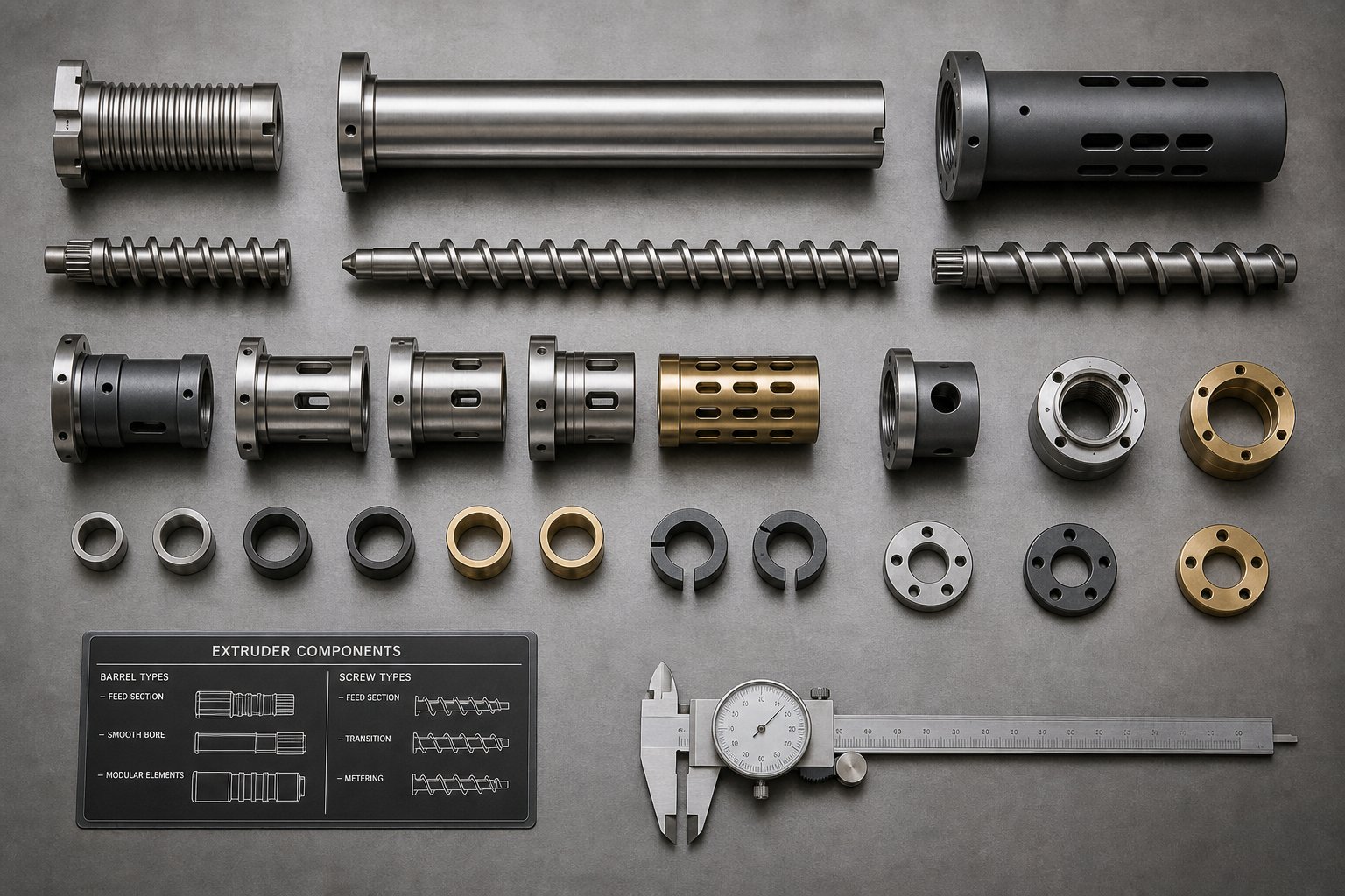
How to Select the Right Barrel Extruder Configuration
Every section of this article has examined a single barrel variable in isolation — bore geometry, L/D ratio, feed-section design, wear mechanisms, thermal zoning, metallurgy, and maintenance strategy. In practice, these variables never exist in isolation. They interact, constrain, and amplify each other in ways that make barrel specification a system-level engineering decision, not a component-level purchase. Selecting the right extruder barrel configuration requires walking through those variables in a deliberate sequence — one where each choice narrows the options for the next — until the full specification emerges from the process requirements rather than from habit, catalog browsing, or whatever the last barrel happened to be.
A Step-by-Step Barrel Extruder Selection Framework
Think of barrel selection as a funnel. You start with broad constraints defined by your polymer and process, and each decision filters the remaining options until only the correct configuration survives. Skipping a step — or reversing the sequence — leads to specifications that look reasonable on paper but underperform in production. Here is the decision sequence that experienced engineers follow:
- Define the polymer system and filler content. This is always the starting point because it determines barrel metallurgy — the single most expensive variable to change after installation. Unfilled commodity resins (PE, PP, PS) permit nitrided steel. Glass-fiber loadings above 15% demand bimetallic iron-boron or tungsten-carbide liners. Corrosive polymers like PVC and fluoropolymers require nickel-alloy liners regardless of filler content. Recycled streams with unknown contaminant profiles should be specified one metallurgical tier above the virgin-material equivalent. Getting this decision wrong means either premature barrel failure (if under-specified) or unnecessary capital expenditure (if over-specified).
- Establish production volume and throughput targets. Your required output rate in kg/hr dictates bore diameter. Larger diameters process more material per screw revolution, but they also increase barrel cost, require larger drive systems, and demand more floor space. Match diameter to throughput, not to aspiration — an oversized barrel running at low screw speeds wastes energy and produces excessive residence time that can degrade heat-sensitive polymers.
- Select the L/D ratio based on processing complexity. Simple melting and pumping of pre-compounded pellets works at 24:1 to 28:1. Vented configurations for moisture-sensitive resins need 28:1 to 32:1 minimum. Intensive compounding, reactive extrusion, or heavily filled systems push the requirement to 32:1 to 40:1. Remember that every additional unit of L/D increases barrel cost, energy consumption, and residence time — specify enough length for the process, but no more.
- Choose single-screw or twin-screw architecture. If the process involves straightforward melting and pumping of uniform pellets — pipe, film, sheet, cable — a single-screw barrel delivers lower capital cost, simpler maintenance, and proven reliability. If the process demands intensive dispersive mixing, positive-displacement conveying of powders or flakes, reactive chemistry, or multi-component compounding, a twin-screw barrel is not optional — it is a process requirement. Twin-screw barrels cost two to five times more and carry higher maintenance complexity, so specifying them without a genuine mixing or conveying need wastes budget.
- Determine feed-section configuration — smooth bore or grooved. Dedicated polyolefin lines running high-viscosity HDPE or LLDPE at maximum output benefit from grooved feed barrels, which deliver 20-40% higher throughput per RPM than smooth bore equivalents. Processors running multiple resin families, engineering plastics, or frequent material changes should default to smooth bore for its broader compatibility and lower drive-system demands.
- Decide on vented vs. non-vented construction. Hygroscopic resins (nylon, PC, PET), recycled feedstock with surface moisture, and any compound releasing volatiles during processing benefit from vented barrel configurations. Non-vented barrels suffice for pre-dried materials and commodity resins with low volatile content. Vented designs add barrel length and cost, but they can eliminate the need for external pre-drying systems — a tradeoff worth calculating on a case-by-case basis.
- Verify compatibility with existing screw design, drive system, and downstream equipment. A barrel does not operate in isolation. Its bore diameter must match the screw. Its flange dimensions must mate with the gearbox adapter and die head. Its thermal zones must align with the controller's channel count. And its metallurgy must pair appropriately with the screw's surface treatment to avoid mismatched hardness that accelerates wear on the more expensive component.
Barrel specification is not a component-level decision — it is a system-level decision that must account for screw design, drive capability, thermal control infrastructure, and downstream equipment before a single dimension is committed to a purchase order.
Following this sequence prevents the two most common specification errors: over-specifying metallurgy on a barrel that processes unfilled commodity resins (wasting capital), and under-specifying metallurgy on a barrel that faces glass fiber or corrosive attack (wasting far more capital through premature failure and unplanned downtime).
Total Cost of Ownership and Emerging Barrel Technologies
Purchase price is the number on the quote. Total cost of ownership is the number that actually matters. A barrel extruder total cost of ownership analysis must capture every cost that accumulates over the barrel's installed life — not just the invoice amount, but the energy it consumes, the maintenance it demands, the downtime it causes, and the product quality it enables or compromises.
Consider the math. A nitrided steel barrel for a 90 mm single-screw extruder might cost $8,000-$12,000. A bimetallic alternative for the same machine runs $25,000-$35,000. On a purchase-order comparison, the nitrided barrel wins by a wide margin. But if that machine processes 30% glass-filled nylon, documented wear data shows nitrided bores lasting roughly 4,000-4,500 operating hours before clearance exceeds tolerance — compared to 15,000-20,000 hours for a properly specified bimetallic liner. Over a 36-month production horizon running 6,000 hours per year (18,000 total hours), the nitrided barrel requires four replacements. The bimetallic barrel requires one, possibly none. Factor in $12,000-$40,000 in lost production per unplanned shutdown event, $500-$1,200 in maintenance labor per barrel change, and 6-12% higher specific energy consumption as clearance widens through each wear cycle — and the "cheap" barrel's 36-month cost often exceeds the premium alternative by 60% or more.
Five cost categories belong in every TCO calculation:
- Initial barrel purchase and installation cost — The line item everyone captures.
- Replacement frequency over the planning horizon — Determined by wear rate, which depends on metallurgy-to-polymer match. A barrel that lasts 4x longer is not 4x more expensive to buy.
- Downtime cost per replacement event — For continuous extrusion lines producing $1,500-$5,000 of saleable product per hour, a single unplanned 8-hour shutdown costs $12,000 to $40,000 in lost production before accounting for scrap, restart waste, and order disruption.
- Energy efficiency over the barrel's life — As bore clearance widens, pumping efficiency drops and operators compensate with higher screw speed, consuming more energy per kilogram of output. Studies document 6% to 12% increases in specific energy consumption as clearance grows from 0.1 mm to 0.5 mm in a 90 mm barrel.
- Quality cost from clearance-driven melt variation — Wider clearance broadens residence-time distribution and degrades melt homogeneity. In precision applications — automotive compounding, medical tubing, optical film — a single quality event triggered by worn-barrel melt inconsistency can generate scrap costs exceeding $50,000.
The arithmetic consistently rewards the same pattern: matching barrel metallurgy to the actual wear environment, paying the upfront premium for the correct specification, and maintaining a disciplined inspection program that catches wear trends before they become production emergencies.
Beyond metallurgy and maintenance strategy, several emerging technologies are reshaping what a barrel extruder can deliver in terms of efficiency, longevity, and process intelligence.
Advanced wear-resistant alloys continue to push the performance envelope. Nanostructured tungsten carbide coatings — using sub-200 nm carbide grain sizes — achieve 15-25% higher hardness than conventional WC formulations at equivalent binder content, with improved fracture toughness from the finer grain distribution. In standardized ASTM G65 abrasion testing, nano-WC coatings demonstrate roughly 67% lower wear loss than their conventional counterparts. As commercial powder availability expands, these coatings are transitioning from laboratory curiosity to production-viable barrel liner specifications.
Energy-efficient barrel design trends target the thermal envelope. Ceramic heater bands with integrated insulation already reduce barrel-zone energy consumption by 25-30% compared to uninsulated mica elements — a savings that compounds across 8,000+ operating hours per year. Newer barrel designs incorporate optimized cooling channel geometries that improve heat removal efficiency without increasing water consumption, and some manufacturers are exploring induction heating systems that offer faster thermal response and tighter zone-to-zone temperature control than resistive heater bands.
Smart sensor integration is accelerating across the industry. Approximately 51% of newly installed extruders now include embedded torque, melt pressure, and barrel temperature sensors that feed predictive maintenance algorithms. Systems like Coperion's Lifecycle Manager use operating-hour data and performance trends to forecast service needs and log maintenance history, while GL Control's Citris system optically scans barrel bore geometry to generate 3D wear maps from up to 50 million data points — giving maintenance teams a data-backed basis for repair or replacement decisions. These tools do not replace bore gauges and manual inspection protocols, but they add a continuous monitoring layer that catches anomalies between scheduled inspections.
Recycled and bio-based polymer compatibility is driving specification changes that many plants have not yet acknowledged. Recycled polymer streams carry higher levels of contamination — metal fines, mineral grit, printing ink residues — that accelerate barrel wear compared to virgin resin service. Bio-based polymers like PLA and PHA process at narrower temperature windows, extending residence time and exposing barrel surfaces to longer thermal-chemical exposure. Both trends push barrel metallurgy upward — applications that ran comfortably on nitrided steel with virgin feedstock may demand bimetallic liners when the same line switches to recycled or bio-based inputs.
Selecting the right extruder barrel specification for compounding applications — or any application — ultimately comes down to one discipline: aligning every barrel variable with the actual process requirements rather than defaulting to the last spec sheet in the file cabinet. The polymer determines metallurgy. Throughput determines bore size. Process complexity determines architecture. And total cost of ownership determines whether the specification decision was engineering-driven or purchasing-driven. Only one of those approaches reliably protects your production uptime and your budget over a multi-year horizon.
For equipment manufacturers and procurement managers comparing barrel options across applications, suppliers specializing in screw and barrel components can streamline the evaluation process considerably. NANHAIYA's product catalog, for example, spans extrusion and injection molding barrel configurations alongside matched screw components — providing a single reference point for comparing metallurgical options, dimensional specifications, and application compatibility without assembling quotes from multiple vendors. Having that consolidated view, regardless of which supplier you ultimately select, accelerates the specification process and reduces the risk of mismatched components arriving on your dock.
Barrel Extruder FAQs
1. What is a barrel extruder and what does it do?
A barrel extruder is the cylindrical steel housing in an extrusion machine that encloses a rotating screw. It serves three simultaneous functions: containing polymer melt under pressures up to 400 bar, acting as a heat transfer surface divided into independently controlled thermal zones, and providing a wear-resistant bore that withstands abrasive fillers, corrosive polymer byproducts, and metal-to-metal screw contact. Together with the screw, the barrel converts solid plastic pellets into a pressurized, homogeneous melt suitable for shaping through a die. Its geometry, metallurgy, and thermal configuration directly determine output rate, melt quality, energy efficiency, and maintenance costs across the entire production line.
2. How do I choose between a single-screw and twin-screw extruder barrel?
The choice depends on your feedstock form and how much transformation the melt requires. Single-screw barrels feature a round cylindrical bore and use frictional drag to convey pre-compounded pellets — ideal for pipe, film, sheet, and cable extrusion where straightforward melting and pumping are sufficient. Twin-screw barrels use a figure-eight bore geometry that enables intermeshing screws and positive displacement conveying, making them necessary for compounding, masterbatch production, reactive extrusion, PVC processing, and devolatilization. Twin-screw configurations cost two to five times more and demand deeper process expertise, so specifying them without a genuine mixing or conveying requirement wastes capital. Suppliers like NANHAIYA (nhyscrews.com/products) offer both configurations, simplifying side-by-side comparison during the evaluation stage.
3. What barrel liner material should I use for glass-fiber-reinforced plastics?
Glass-fiber-reinforced compounds are among the most abrasive materials processed in extrusion, eroding barrel bores at five to ten times the rate of unfilled resins. Nitrided steel barrels are inadequate — their thin hardened layer wears through quickly, often within 4,000 operating hours. Bimetallic iron-boron alloy liners (58-65 HRC) are the standard recommendation for glass loadings up to roughly 30%. For heavily reinforced compounds exceeding 40% glass content, tungsten-carbide composite liners with hardness values above 1,100 HV provide several times the service life of standard bimetallic liners. Though tungsten-carbide liners carry a significant cost premium, total cost of ownership calculations consistently favor them because they dramatically reduce replacement frequency, unplanned downtime, and scrap from clearance-driven melt inconsistency.
4. How often should I inspect and measure my extruder barrel bore?
Inspection intervals should be based on operating hours rather than calendar time, and adjusted to match the aggressiveness of the material being processed. For unfilled commodity resins like PE, PP, and PS, inspect every 4,000 to 5,000 hours. For glass-fiber-reinforced or mineral-filled compounds, shorten that interval to 1,500 to 2,500 hours. Corrosive polymers such as PVC and fluoropolymers warrant inspection every 1,000 to 2,000 hours during the first year, with intervals adjusted based on observed wear rates. Each inspection should include bore diameter measurements at 100-150 mm intervals along the full barrel length, visual liner condition checks via bore scope, heater band continuity tests, thermocouple calibration verification, and cooling channel flow rate measurement. Logging this data over time creates wear-rate trend lines that enable predictive replacement scheduling.
5. What is the difference between smooth bore and grooved feed extruder barrels?
Smooth bore barrels rely on frictional drag between polymer pellets and the barrel wall to convey solids forward. This makes them sensitive to feed-zone temperature and polymer surface characteristics, but highly versatile across a broad range of resin types including engineering plastics and frequent material changes. Grooved feed barrels use machined grooves in the feed zone to mechanically lock pellets, creating a positive-displacement conveying effect that is largely independent of friction. This delivers 20-40% higher throughput per RPM for polyolefins like HDPE and LLDPE, but generates feed-zone pressures up to 15,000-20,000 psi — requiring heavier thrust bearings, larger gearboxes, and dedicated screw designs with shallower feed channels. Grooved barrels perform best in dedicated, single-resin polyolefin operations at high output rates, while smooth bore designs suit multi-resin plants and engineering plastic applications.
Written by
Nanhaiya Technical Team
Zhoushan Nanhaiya Plastic Machinery Co., Ltd.
The Nanhaiya technical team supports screw and barrel manufacturing projects through application review, technical communication, custom manufacturing coordination, and production and quality control.
Discuss Your Application
Related Articles
More insights on screw barrel technology and plastics processing.

What Nobody Tells You About Screw Barrel For Plastic Machine Design
Oct 10, 2026
Learn how screw barrel for plastic machine design affects melt quality, throughput, and wear life. Covers geometry, resin matching, troubleshooting, and sourcing.
Read Article
Single Screw Extruder for Sheet: Stop Guessing, Start Specifying
Oct 9, 2026
Learn how to specify a single screw extruder for sheet production. Covers screw geometry, resin-specific processing, troubleshooting, and maintenance best practices.
Read Article
PE Pipe Extruder Machine: What Datasheets Won't Tell You
Oct 9, 2026
Learn how a PE pipe extruder machine works, key specs explained, material grade selection, maintenance tips, and buyer guidance beyond the datasheet.
Read ArticleLooking for something else?
Search by material, symptom or product and jump straight to the relevant page.
These are navigation suggestions based on keyword matching — not a quotation, not a delivery commitment, and not a substitute for engineering review. Final specification is confirmed by our engineers against your drawings and processed material.
Need help with screw barrel selection?
Share your machine model, processed material and application. Our team can help with pricing and technical support.