

Understanding the Extruder Screw and Barrel System
Imagine running a plastics production line where melt quality fluctuates, scrap rates creep upward, and energy bills keep climbing - yet nobody can pinpoint the root cause. More often than not, the answer lies in two components sitting at the very heart of the machine: the extruder screw and barrel.
What Is an Extruder Screw and Barrel System
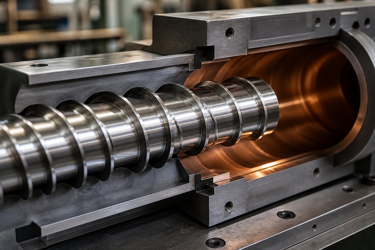
An extruder screw and barrel system is the core plasticating unit in any extrusion or injection molding machine. Its job is to convey, melt, mix, and pressurize polymer material into a homogeneous melt that can be shaped into a finished product. Every thermoplastic part you encounter - from packaging film to automotive trim - passed through one of these systems before it took its final form.
The screw is the rotating element inside the machine. Driven by a motor and gearbox, it transports raw plastic pellets forward along its helical flights, generating frictional heat and mechanical shear that transform solid granules into molten polymer. The barrel is the stationary cylindrical housing surrounding the screw. It provides structural containment, supports external heaters and cooling circuits, and creates the controlled thermal environment necessary for consistent plastication. Together, the screw and barrel form an integrated system where geometry, metallurgy, and thermal management determine three critical outcomes: melt quality, throughput rate, and energy efficiency.
As SpecialChem's extrusion guide notes, the screw and the barrel that contains it are the core of the extrusion process - all other components of the extruder exist to support them. External heaters combined with mechanical shear from the screw generate the heat needed to produce a homogeneous molten state, while proper temperature control remains critical for melt quality.
Why the Screw and Barrel Matter in Plastics Processing
You'll notice that discussions about extruder screws and barrels often focus on dimensions and materials. That's important, but the real story is economic. These components directly influence product quality, cycle times, scrap rates, and operating costs across every plasticating process - whether you're running blown film, pipe extrusion, compounding, or injection molding.
The screw and barrel account for the majority of energy consumption and quality variability in any plasticating process.
Consider what happens when an extruder screw wears beyond acceptable tolerances. Industry experience shows that operators begin compensating - increasing screw speed, adjusting barrel temperatures, raising backpressure - often without realizing these incremental changes are masking a deeper problem. According to plastics processing experts at Plastics Technology, these adjustments typically use more energy and affect part quality, and at some point they reach a "point of diminishing returns" where productivity and quality suffer noticeably.
A well-selected screw design matched to the right barrel configuration, on the other hand, delivers stable melt temperatures, consistent output, lower specific energy consumption, and longer service intervals. The difference between guessing and getting it right shows up directly on the production floor - and on the balance sheet.
This guide takes a vendor-neutral, educational approach to the full lifecycle of extruder screws and barrels. From screw geometry and barrel metallurgy through polymer-specific design matching, maintenance strategies, and total cost of ownership, each section builds a practical framework for making informed decisions rather than relying on trial and error.
Anatomy of the Screw and Barrel Assembly
Knowing that the screw and barrel drive melt quality, throughput, and energy costs is one thing. Understanding exactly how they do it requires a closer look at their physical structure. Every curve, channel depth, and surface finish serves a deliberate processing purpose - and when you can read the anatomy, you can start diagnosing problems and making smarter selection decisions.
Screw Anatomy and the Three Functional Zones
Picture a single-flighted extruder screw laid out on a workbench. From the drive end to the tip, you'll notice the channel between the helical flights isn't uniform. It changes depth deliberately, creating three distinct functional zones that each handle a different stage of polymer processing.
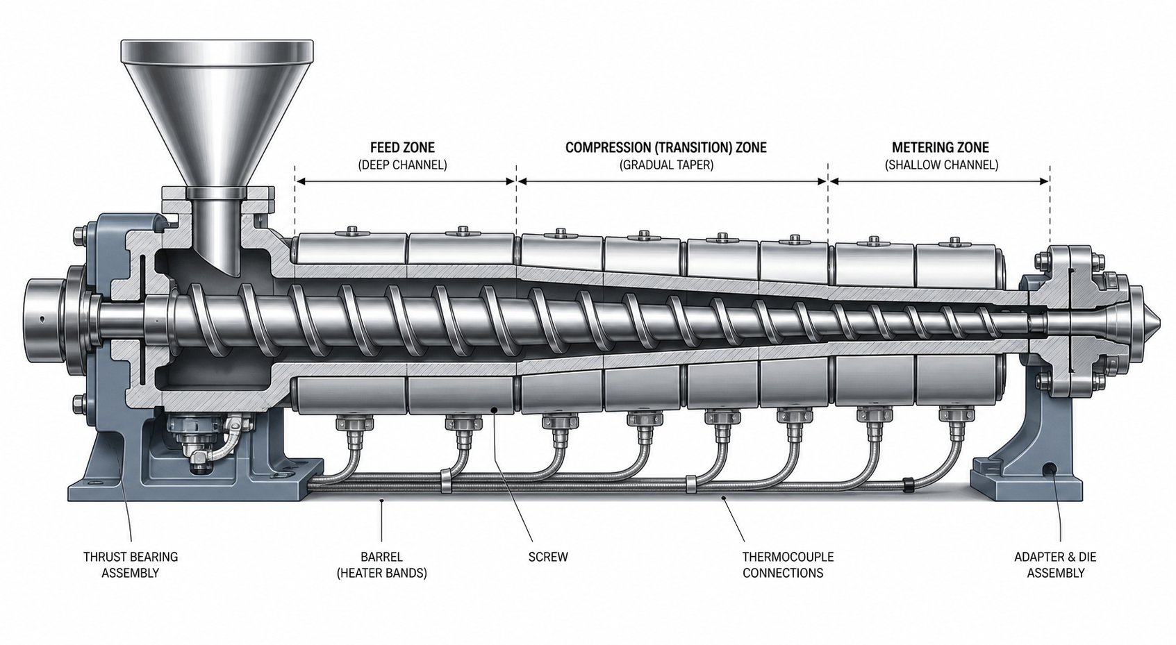
- Feed zone: This is where solid pellets enter the screw barrel system. The channel here is at its deepest, providing maximum volume to accept and convey incoming resin. Solids conveying depends heavily on friction between the pellets, the barrel wall, and the screw root. The goal is simple: grab raw material and push it forward reliably.
- Transition (compression) zone: Here the channel depth gradually decreases, compressing the solid bed against the heated extruder barrel wall. This compression, combined with barrel heat and frictional shear, initiates melting. The decreasing volume forces air out of the pellet bed and creates the pressure needed to drive the phase change from solid to melt. As NC State Extension research explains, screw channel depth decreases in the order: conveying zone > compression zone > metering zone, with each step deliberately increasing shear input into the material.
- Metering zone: The shallowest channel section. By this point, the polymer should be fully molten. The metering zone's job is to homogenize the melt - ensuring uniform temperature and viscosity - and to build consistent pressure for delivery through the die or nozzle.
These three zones work as a continuous system. A feed zone that conveys inconsistently starves the compression zone. A compression zone that melts too aggressively can overshear sensitive polymers. A metering zone with the wrong depth may fail to develop adequate pressure. Everything connects.
Several geometric parameters define how a screw performs across these zones:
- L/D ratio (length-to-diameter): The total flighted length of the screw divided by its nominal diameter. Higher L/D ratios give the polymer more residence time and processing length, which generally improves melting and mixing. Common values range from 20:1 to 36:1, depending on the application.
- Compression ratio: The ratio of the feed zone channel depth to the metering zone channel depth. This tells you how aggressively the screw compresses material during melting. Semi-crystalline polymers like PE and PP typically need higher compression ratios (3:1 to 4:1) because of their sharp density change during melting, while amorphous resins like PS can work with lower ratios (2:1 to 2.5:1).
- Helix angle: The angle of the flight relative to a plane perpendicular to the screw axis. Standard screws use a 17.66-degree helix angle (corresponding to a square pitch, where pitch equals diameter), but variations alter conveying efficiency and shear characteristics.
- Flight width: The land width at the top of the flight. Wider flights provide more sealing against backflow but also generate more shear heat in the thin film of melt between the flight tip and barrel wall.
These dimensions don't operate independently. Changing the compression ratio without considering L/D can create pressure spikes. Adjusting helix angle affects both conveying rate and residence time. Successful screw design is about balancing all of these parameters against a specific polymer and process target.
Barrel Construction and Heating-Cooling Zone Layout
The extruder barrel does far more than simply contain the screw. It provides the thermal framework that makes controlled plastication possible. A modern extrusion barrel is divided into multiple independent heating and cooling zones, each managed by its own heater bands, thermocouples, and often cooling fans or water channels. This segmented design lets process engineers create a tailored temperature gradient along the entire length of the machine.
Why does this matter? Different polymers demand different thermal profiles. Amorphous polymers like polycarbonate or polystyrene soften gradually over a wide temperature range, so barrel zones can ramp up relatively smoothly. Semi-crystalline polymers like polyethylene or nylon, on the other hand, have a narrow melting point and require more aggressive heat input in the compression zone to ensure complete crystal structure breakdown. Failing to match the barrel's thermal profile to the polymer's melting behavior leads to unmelted particles in the output, or at the other extreme, degraded material from excessive heat exposure.
One of the most overlooked areas of the extruder feed barrel is the feed throat - the opening where pellets first enter the barrel. This section typically requires active water cooling to keep the barrel wall temperature well below the polymer's softening point. Without adequate cooling, pellets begin to soften and stick before the screw flights can convey them forward. The result is "bridging" - a plug of partially melted resin that blocks the feed opening, starves the screw, and forces a production stop.
| Zone Name | Typical Temperature Range | Primary Function |
|---|---|---|
| Feed Throat / Zone 1 | Cooled (40-70 °C / 100-160 °F) | Prevent premature melting; ensure consistent solids conveying into the screw |
| Feed / Early Barrel Zones | 150-200 °C (300-390 °F)* | Begin preheating pellets; promote friction-driven conveying against barrel wall |
| Transition / Compression Zones | 200-250 °C (390-480 °F)* | Deliver majority of melting energy; compress solid bed to expel trapped air |
| Metering / Final Barrel Zones | 210-260 °C (410-500 °F)* | Homogenize melt temperature and viscosity; build stable output pressure |
*Ranges shown are representative for common polyolefins and styrenics. Actual setpoints vary significantly by polymer type, screw speed, and throughput rate.
Each zone's heater and cooling system operates through a feedback loop - typically a PID controller - that maintains the barrel wall temperature at its setpoint. As industry practitioners note, even small deviations of a few degrees can impact melt consistency, so independent zone control and properly placed thermocouples are essential for repeatable results.
How Screw-to-Barrel Clearance Affects Performance
Here's a detail that rarely gets the attention it deserves: the radial gap between the screw flight tip and the barrel inner wall. This clearance is intentionally small - typically on the order of 0.1 to 0.15 mm per side for a standard-sized screw (roughly 0.1% of barrel diameter, though exact values depend on the manufacturer and application). That tight gap isn't arbitrary. It directly controls how well the screw seals against backflow.
When this clearance grows due to wear, polymer melt leaks backward over the flight tips instead of being pushed forward. Industry analysis from Plastics Technology confirms that as radial clearance increases, the screw loses pumping efficiency. Operators typically see reduced throughput and rising melt temperatures, forcing higher RPM and greater energy consumption just to maintain the same output rate. A common industry rule of thumb considers a flight clearance four times the original tolerance as the cutoff point for screw replacement - though higher-viscosity resins tolerate more clearance than low-viscosity materials before output loss becomes significant.
On the other side of the equation, clearance that's too tight creates its own problems. Metal-to-metal contact between the flight OD and barrel ID accelerates wear on both components, drives up motor amperage, and can generate localized overheating. As the same source explains, while general high internal pressure alone doesn't deflect the screw into the barrel wall, mechanical issues like misalignment, bent screws, or gearbox damage can cause intermittent metal-to-metal contact that compounds wear dramatically.
The takeaway? Clearance is a balancing act. Too loose, and you lose throughput, waste energy, and sacrifice melt uniformity. Too tight, and you accelerate wear and risk damaging expensive components. Monitoring this gap through regular bore gauging and screw OD measurement is one of the simplest - yet most impactful - maintenance practices available.
With the physical structure of these components mapped out, the next logical question is: which screw design geometry best fits a given polymer and process? The answer varies considerably depending on whether you're running a straightforward polyolefin or a demanding filled compound - and the range of available screw architectures is broader than many processors realize.
Screw Design Types and When to Use Each
A standard three-zone screw handles a surprisingly wide range of resins - but "handles" and "optimizes" are very different things. When throughput targets rise, polymer complexity increases, or quality tolerances tighten, generic screw geometry starts leaving performance on the table. That's where specialized extrusion screw designs come in, each engineered to solve a specific processing bottleneck that a general-purpose profile simply can't address.
General-Purpose vs. Barrier Screw Designs
The standard single-flighted metering screw - the workhorse of the industry - uses one continuous helical flight to convey, compress, and meter the polymer. It's simple, economical, and adequate for many applications. But it has an inherent limitation: solid pellets and molten resin share the same channel space throughout the transition zone. This co-mingling leads to an unstable solid bed that can break apart unpredictably, causing output surging and temperature inconsistency.
Barrier screws solve this by introducing a secondary flight - the barrier flight - that physically separates the remaining solids from the growing melt pool. As the melt forms, it crosses over the barrier flight into a dedicated melt channel, while unmelted solids stay confined in a progressively narrowing solids channel. The result is more controlled, predictable melting and significantly more consistent output.
Two principal barrier architectures dominate. The crossing (Maillefer) type was one of the earliest designs, featuring a barrier flight that crosses the main flight helix at an angle. The parallel (Barr) type uses a barrier flight that runs roughly parallel to the main flight, creating a wider solids channel. As screw design expert Jim Frankland explains, parallel barrier designs typically offer approximately one-third more melting area in the solids channel compared to crossing types of the same axial length. That makes them better suited for polymers with higher melting energy requirements - materials with high melting points, high specific heats, or strong shear-thinning behavior.
Crossing barriers, by contrast, excel with polymers having lower energy requirements. They also avoid the sudden restriction of solids-channel width at the barrier start, which can be an advantage for hard or slippery resins whose fragile solid beds don't easily reshape to accommodate abrupt geometry changes. Modifications to both types - such as the Dray-Lawrence variant with increased helix angles in the barrier section - aim to boost volume capacity for higher output, though Frankland notes the actual improvement in melting capacity per unit length remains modest unless the axial barrier length itself is extended.
When should you choose a barrier design over a conventional plastic extrusion screw? Whenever melting consistency and output stability are priorities - particularly in high-throughput blown film, sheet extrusion, and pipe lines running semi-crystalline polyolefins where solid bed breakup is a common source of quality variability.
Mixing Screws and Vented Degassing Configurations
Melting is only half the battle. Many applications also demand thorough mixing - whether to distribute color concentrates evenly, break down filler agglomerates, or blend polymer components into a homogeneous melt. Mixing performance in a plastic extruder screw depends on two fundamentally different mechanisms: distributive and dispersive mixing.
Distributive mixing spreads minor components uniformly throughout the melt without necessarily applying high stress. Think of it as stirring cream into coffee. Pin mixing sections, pineapple tips, and cavity transfer elements are common distributive devices. They repeatedly split and recombine the melt stream, increasing spatial uniformity. These sections are ideal for blending color masterbatch, liquid additives, or low-viscosity components where you need even spatial distribution rather than particle size reduction.
Dispersive mixing, on the other hand, applies high shear stress to break apart agglomerates, gels, or undispersed particles. Research from Paderborn University using 3D CFD simulations with particle tracking confirmed that screw element geometry has a significant influence on dispersive mixing performance - toothed mixing elements (ZME) generated substantially higher and more uniformly distributed shear stresses compared to kneading blocks and conveying elements. In single-screw systems, Maddock (Union Carbide) mixers and blister rings serve the dispersive role, forcing melt through a narrow restrictive gap where high shear stress breaks down contaminants and agglomerates. You'll typically find these specified for glass-fiber-filled compounds, recycled resins with contaminants, or any process where undispersed particles would compromise final part performance.
Many plastic extruder screw designs combine both mixing types in sequence - a dispersive section to break down agglomerates, followed by a distributive section to spread them uniformly - creating a "mixed-mixing" screw optimized for compounding and color-critical applications.
Vented or degassing screw configurations address a different problem entirely. Some polymers absorb moisture (nylon, PET, PC) or release volatiles during processing. A vented screw extrusion design includes a decompression zone where channel depth increases abruptly, dropping melt pressure to near-zero. At this point, a vent port in the barrel allows moisture and volatiles to escape - often assisted by vacuum. The screw then recompresses and meters the degassed melt forward. This approach can eliminate the need for expensive pre-drying equipment and reduce cycle times for hygroscopic resins, though it requires careful screw geometry to prevent melt from flowing out through the vent port.
Grooved Feed and High-Speed Extrusion Screws
One of the most impactful innovations in screw extrusion over the past several decades involves redesigning the barrel, not just the screw. Grooved feed barrels feature longitudinal or helical grooves machined into the feed zone bore. These grooves lock pellets against the barrel wall, dramatically increasing solids conveying friction independent of the polymer's natural coefficient of friction. The result? Higher throughput at lower melt temperatures, with conveying performance that's largely independent of downstream die back pressure.
Experimental research from the University of Stuttgart investigated solid conveying behavior in smooth, helically grooved, and axially grooved barrels at screw speeds up to 1350 rpm. Their findings confirmed that grooved feed zones deliver significantly higher mass throughput compared to smooth barrels - roughly double at conventional speeds. Importantly, the study also demonstrated that grooved systems maintain counter-pressure-independent conveying: increasing die back pressure from 50 bar to 200 bar had no measurable effect on throughput in the helically grooved setup, whereas smooth barrel systems showed significant throughput reduction under back pressure.
At high screw speeds, however, interesting limitations emerge. The same research revealed that the specific throughput (output per revolution) begins to drop above a threshold speed - typically around 300 rpm for lenticular and cylindrical pellets, though small spherical granules maintained linear throughput up to 600-1200 rpm depending on barrel type. Granule shape and size, it turns out, play a decisive role in high-speed feeding behavior.
Energy-efficient screw profiles designed for these high-speed grooved-feed lines leverage the elevated feed pressure to reduce the melting burden on barrel heaters. Because solids are delivered under higher pressure and with greater consistency, compression zones can be shorter and shear input lower, keeping melt temperatures down even at elevated output rates. This combination - grooved feed barrel plus optimized barrier screw - represents the current state of the art for high-throughput polyolefin extrusion in pipe, film, and sheet applications.
| Screw Type | Ideal Polymer Types | Typical L/D Ratio Range | Compression Ratio Range | Key Advantages | Limitations |
|---|---|---|---|---|---|
| General-Purpose (3-Zone) | PE, PP, PS, ABS - broad range of standard resins | 20:1 - 30:1 | 2.0:1 - 4.0:1 | Simple, economical, widely available, easy to maintain | Limited melting uniformity at high throughput; solid bed breakup risk |
| Barrier - Crossing (Maillefer) | Low-energy-requirement polymers: PS, LDPE, flexible PVC | 24:1 - 30:1 | 2.5:1 - 3.5:1 | No abrupt solids channel restriction; good for fragile solid beds; higher head-pressure capability | Less melting area than parallel types; may under-perform with high-melting-point resins |
| Barrier - Parallel (Barr) | Higher-energy polymers: HDPE, PP, nylon, PET | 24:1 - 33:1 | 2.5:1 - 3.5:1 | ~33% more melting area vs. crossing types; excellent melt consistency and output stability | May need metering section after barrier to build head pressure; sensitivity at barrier start |
| Mixing (Dispersive / Distributive) | Filled compounds, color-critical products, recycled resins | 24:1 - 36:1 | 2.0:1 - 3.5:1 | Breaks agglomerates (dispersive) or spreads additives evenly (distributive) | Adds pressure drop; dispersive elements increase shear and melt temperature |
| Vented / Degassing | Hygroscopic resins: nylon, PET, PC; volatile-releasing polymers | 30:1 - 36:1 | Dual stage (2.5-3.5:1 each stage) | Eliminates pre-drying; removes moisture and volatiles in-process | Requires precise geometry to prevent vent flow; longer screw needed; reduced output vs. non-vented |
| Grooved Feed / High-Speed | Polyolefins (HDPE, LLDPE, PP) for high-throughput extrusion | 30:1 - 36:1 | 1.5:1 - 2.5:1 (lower due to high feed pressure) | Throughput independent of back pressure; lower melt temperatures; high output per screw revolution | Requires specially grooved barrel; higher feed zone pressure demands robust barrel/screw metallurgy |
Selecting the right screw architecture is really about matching the dominant processing challenge - whether that's melting capacity, mixing intensity, moisture removal, or feed stability - to the geometry best equipped to handle it. Yet geometry alone doesn't tell the full story. A single-screw system and a twin-screw system might both use barrier or mixing elements, but the fundamental conveying and mixing mechanisms differ so profoundly that the choice between them deserves its own careful evaluation.

Single-Screw vs. Twin-Screw Barrel and Screw Systems
Screw geometry determines how polymer is processed - but the number of screws inside the barrel changes the fundamental physics of why material moves and mixes in the first place. A single screw extruder and a twin-screw system aren't just different sizes of the same idea. They rely on entirely different conveying mechanisms, and choosing the wrong platform for your application can cost far more than the price difference between the two machines.
Single-Screw Extruder Barrel and Screw Fundamentals
Picture a single screw rotating inside a smooth cylindrical barrel. What actually pushes the polymer forward? It's not the screw flights scooping material like an auger - it's drag flow. The barrel wall grabs the melt through friction and viscous drag, while the rotating screw channels redirect that grip into forward motion. Without adequate friction between the resin and the barrel surface, conveying stalls regardless of how fast the screw turns.
This drag-flow mechanism makes single-screw systems inherently well suited for steady-state processing. When you're running a pre-compounded resin at consistent throughput - think PE pipe, PS sheet, or PET preform production - the simplicity of a single screw barrel setup offers real advantages:
- Lower capital cost: One screw, one barrel bore, and a straightforward gearbox mean significantly less initial investment compared to twin-screw alternatives.
- Simpler maintenance: Fewer moving parts translate to fewer failure modes. Screw pulls, bore inspections, and component replacements are all more accessible.
- Proven reliability: Single-screw extruders have decades of operational history across virtually every thermoplastic application, and spare parts are widely available.
- Efficient for dedicated lines: When you're processing one material family on a dedicated production line, the single-screw platform delivers excellent cost-per-kilogram performance.
The trade-off? Limited mixing capability. Because the polymer travels in a relatively orderly helical path, there's minimal cross-channel mixing compared to what twin-screw systems can achieve. For pre-compounded materials that arrive ready to melt and shape, that's perfectly fine. For operations requiring intensive blending, reactive processing, or devolatilization, the single-screw architecture starts running into fundamental limitations that no screw geometry redesign can fully overcome.
Co-Rotating vs. Counter-Rotating Twin-Screw Systems
Twin-screw systems address those limitations by placing two screws side by side inside a figure-eight barrel bore. But the direction those screws rotate relative to each other creates two dramatically different machines.
Co-rotating intermeshing twin screws - where both screws turn in the same direction - are the industry standard for compounding, reactive extrusion, and devolatilization. Their defining characteristic is self-wiping action: because the screws intermesh and rotate together, each flight tip continuously sweeps material off the opposing screw's surface. This prevents stagnant zones, ensures narrow residence time distribution, and delivers exceptional mixing intensity. As Bausano's technical overview explains, co-rotating extruders create a continuous and uniform flow of polymeric material, making them widely used for applications requiring intensive mixing and efficient plasticization.
Counter-rotating twin screws rotate in opposite directions, creating a fundamentally different flow pattern. Where the screws meet, material is squeezed through a high-pressure nip zone. This generates positive displacement conveying - the enclosed pockets between intermeshing flights act almost like a gear pump, pushing material forward with high volumetric consistency. Counter-rotating systems also tend to apply gentler, more controlled shear compared to their co-rotating counterparts. That makes them a strong choice for shear-sensitive materials. In PVC pipe and profile extrusion, for instance, counter-rotating twinscrew extruders dominate precisely because PVC requires careful thermal management to avoid degradation. The same Bausano source notes that counter-rotating extruders are often preferred when greater plasticization of the material is needed or when processing highly viscous compounds.
One feature that sets twin-screw systems apart from single-screw designs is modular screw element construction. Rather than machining an entire screw from a single shaft, twin screw and barrel platforms use interchangeable elements that slide onto a splined shaft:
- Conveying elements: Standard helical flights that transport material forward. Varying pitch controls residence time and fill level.
- Kneading blocks: Staggered disc elements that apply intensive shear and mixing. Wider stagger angles increase mixing intensity; narrower angles favor conveying.
- Reverse elements: Flights oriented opposite to the conveying direction. These create local back-pressure zones that force material to fully fill upstream mixing sections, maximizing blending efficiency.
This modularity means a single twin screw barrel platform can be reconfigured for different formulations simply by rearranging screw elements - a level of process flexibility that monolithic single-screw designs can't match.
Choosing Between Single and Twin Screw Configurations
So how do you decide which platform fits your operation? The answer depends less on which system is "better" in the abstract and more on which processing demands dominate your specific application. The following comparison breaks down the key decision criteria:
| Criterion | Single-Screw Advantage | Twin-Screw Advantage |
|---|---|---|
| Mixing Capability | Adequate for pre-compounded resins; mixing sections can be added but are inherently limited by drag-flow conveying | Superior distributive and dispersive mixing; self-wiping co-rotating designs excel at blending multi-component formulations |
| Throughput Flexibility | Output is coupled to screw speed; limited independent control of feed rate vs. screw RPM | Starve-fed operation decouples feed rate from screw speed, enabling precise throughput control and recipe changes |
| Capital Cost | Significantly lower purchase price; simpler gearbox, single barrel bore, fewer components | Higher initial investment; complex gearbox, figure-eight barrel, modular screw elements add cost |
| Maintenance Complexity | Fewer wear components; screw pulls and bore inspections are straightforward | More components to inspect and replace; modular elements simplify targeted replacement but overall maintenance burden is higher |
| Material Versatility | Best for running one resin family on a dedicated line; changeovers are slower | Handles frequent formulation changes; modular screw design adapts to different polymers, fillers, and additive packages |
| Residence Time Distribution | Broader residence time distribution; acceptable for most extrusion but less controlled | Narrow, well-defined residence time distribution; critical for heat-sensitive materials and reactive processing |
Choose single-screw for dedicated processing of pre-compounded resins where simplicity and cost efficiency matter most. Choose twin-screw when mixing intensity, formulation flexibility, or devolatilization are primary process requirements.
In practice, many facilities run both platforms. A co-rotating twin screw extruder handles upstream compounding - blending virgin resin with fillers, stabilizers, and colorants - while downstream single-screw lines take that compounded pellet and shape it into finished products at maximum efficiency. The two architectures aren't competitors so much as complementary stages in a well-designed production workflow.
Whichever platform you select, though, one factor shapes long-term performance more than any geometric or mechanical design choice: the materials those screws and barrels are actually made from. Metallurgy and surface treatments determine how long components last, how well they resist wear and corrosion, and ultimately how much each kilogram of output really costs over the life of the machine.
Barrel and Screw Materials and Protective Coatings
Geometry gets the spotlight, but metallurgy does the heavy lifting. You can specify the perfect compression ratio, barrier flight configuration, and L/D ratio - and still watch your screw and barrel degrade prematurely if the base materials can't withstand the chemical and mechanical demands of your process. Polymers don't just flow passively through the system. They apply abrasive, corrosive, and thermal stress to every internal surface, hour after hour, shift after shift. The alloy grades and surface treatments you select determine whether your components last months or years - and whether output quality holds steady or quietly deteriorates.
Base Alloy Grades and Their Processing Strengths
Walk through any barrel and screw supplier's catalog and you'll encounter a handful of steel designations that keep recurring. Understanding what each one brings to the table - in plain terms, not metallurgical jargon - makes the difference between an informed purchase and an expensive guess.
Nitrided steel (e.g., 38CrMoAlA): This is the industry workhorse. 38CrMoAlA is a chromium-molybdenum-aluminum alloy steel specifically designed for gas nitriding - a thermochemical surface hardening process that diffuses nitrogen into the steel surface, creating a hard case layer while maintaining a tough, ductile core. The result is a screw or extrusion barrel with good surface hardness, reasonable wear resistance, and solid thermal stability at standard processing temperatures. It handles commodity polyolefins (PE, PP), polystyrene, ABS, and other unfilled resins reliably and economically. Think of it as the default starting point: if your process involves standard thermoplastics without abrasive fillers or aggressive chemical attack, nitrided steel delivers an excellent balance of performance and cost.
Structural alloy steel (e.g., 42CrMo): This chromium-molybdenum steel offers high tensile strength and good toughness, making it a common choice for screw core construction - the structural backbone that must resist the torsional loads, bending forces, and cyclic stresses that every screw experiences during operation. While 42CrMo doesn't achieve the surface hardness of nitrided alloys, its strength and fatigue resistance make it ideal as a substrate material. In many screw designs, you'll find a 42CrMo core combined with harder surface treatments or welded flight tips for the best of both worlds: structural integrity underneath, wear resistance on top.
Tool steels (e.g., SKD61 / H13): When processing moves into more demanding territory - glass-fiber-filled nylons, mineral-loaded compounds, or recycled streams with contaminants - tool steels step up. SKD61 (the Japanese JIS equivalent of AISI H13) is a hot-work tool steel with excellent hot hardness, meaning it maintains its strength and wear resistance at elevated temperatures where standard nitrided steels start softening. It's the go-to material for screws running abrasive filler-loaded engineering resins where flight tip erosion would rapidly compromise a softer alloy. The trade-off is cost: tool steel components carry a premium over nitrided options, so they're typically specified where the process severity justifies the investment.
Which polymer families pair best with each material? As a practical rule of thumb:
- Standard polyolefins, PS, ABS (unfilled): Nitrided 38CrMoAlA screws and barrels handle these resins efficiently at the lowest component cost.
- Glass-filled nylon, mineral-filled PP, recycled resins with contaminants: Tool steels like SKD61 resist the abrasive wear that would shorten the life of softer alloys.
- High-torque or large-diameter applications: 42CrMo provides the structural backbone, often paired with hard-facing or bimetallic construction for surface protection.
Bimetallic Barrel Liners and Advanced Surface Treatments
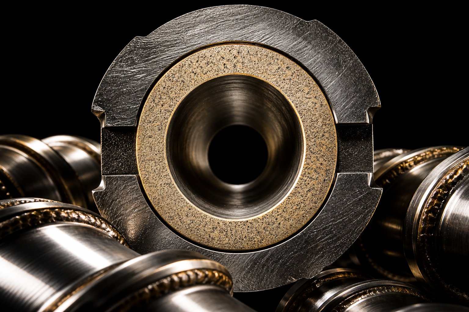
Here's where material science gets particularly interesting for extrusion barrels. Rather than manufacturing an entire barrel from expensive, ultra-hard alloy - which would be prohibitively costly and mechanically impractical - the industry uses bimetallic construction. A wear-resistant inner lining is centrifugally cast inside a structural carbon or alloy steel outer shell. During centrifugal casting, the barrel is spun at high speed while molten liner alloy is poured inside, forcing the lining material outward against the bore wall under centrifugal force. The result is a metallurgical bond between the liner and the outer shell, combining the structural strength and machinability of the outer body with the hardness and chemical resistance of the inner bore surface.
Bimetallic extrusion barrels significantly outperform standard nitrided bores when processing filled compounds, abrasive resins, or corrosive polymers. The liner alloy can be tailored to the specific wear mechanism - whether that's abrasive erosion from glass fibers, corrosive attack from halogenated polymers, or a combination of both.
Beyond bimetallic construction, several surface treatment and coating technologies extend component life even further:
Nitriding remains the most cost-effective surface hardening method for screws and barrels. Gas nitriding at controlled temperatures diffuses nitrogen into the steel surface, creating a hard nitride layer typically 0.3-0.7 mm deep. It's a proven, economical treatment that meaningfully improves wear life for standard resin processing without requiring exotic base materials.
For more severe applications, advanced coatings applied through thermal spray, welding, or chemical vapor deposition provide another tier of protection:
- Tungsten carbide (WC) coatings: The premium choice for extreme abrasive wear resistance. Tungsten carbide coatings achieve hardness values in the range of 1,100-1,400 HV300, providing exponentially greater wear resistance than bare or nitrided steel. They're specified for barrels and screws running highly abrasive compounds - glass-fiber-filled engineering resins, ceramic-loaded masterbatches, or aggressive recycled streams. Modern HVAF (High Velocity Air Fuel) application methods produce dense, non-porous carbide layers that retain ductility despite their extreme hardness.
- Chromium carbide coatings: Offer a strong combination of wear resistance and high-temperature oxidation resistance. They're particularly effective in applications where operating temperatures exceed the comfort zone of tungsten carbide binders, or where moderate abrasion coexists with elevated thermal exposure. A practical mid-tier option between nitriding and full tungsten carbide treatment.
- Nickel-based alloy coatings (e.g., Hastelloy-type): The go-to solution when corrosion is the primary threat rather than abrasion. Nickel alloys resist chemical attack from corrosive polymers like PVC, fluoropolymers (PVDF, FEP), and chlorinated resins that would aggressively degrade standard steels. These coatings also offer good resistance to pitting and stress corrosion cracking in high-temperature, chemically active environments.
- Cobalt-based alloys (e.g., Stellite): Provide a balanced profile of wear resistance, corrosion resistance, and hot hardness. Often applied to screw flight tips via weld overlay, they perform well in combined-wear environments where both abrasion and chemical attack are present simultaneously.
The choice between these coatings depends on your dominant wear mechanism. Running glass-filled nylon? Tungsten carbide is your best defense against abrasive flight-tip erosion. Processing rigid PVC? Nickel-based alloys protect against hydrochloric acid attack. Facing a mix of both? Cobalt alloys or carefully selected bimetallic liners may offer the best all-around compromise.
Matching Metallurgy to Your Process Demands
With so many alloy grades, liner options, and coating technologies available, how do you match the right metallurgy to your specific situation without over-specifying (wasting money) or under-specifying (inviting premature failure)?
A practical selection framework breaks the decision into three tiers based on process severity:
- Standard unfilled resins (PE, PP, PS, ABS): Nitrided 38CrMoAlA screws with standard nitrided barrels. This is the baseline configuration that handles the majority of commodity resin processing at the lowest component cost. Surface hardness from nitriding provides adequate wear resistance for clean, unfilled materials, and replacement costs remain manageable if wear does occur on schedule.
- Filled compounds (glass fiber, mineral fillers, carbon fiber, recycled streams): Bimetallic barrels with wear-resistant centrifugal liners, paired with tool steel or hard-faced screws. Abrasive fillers dramatically accelerate wear on standard nitrided surfaces - a barrel running 30% glass-filled nylon may wear at five to ten times the rate of the same barrel running unfilled resin. The higher upfront investment in bimetallic or tungsten-carbide-coated components pays back through dramatically extended service intervals and more stable output quality over the component's lifetime.
- Corrosive polymers (PVC, CPVC, fluoropolymers, flame-retardant compounds): Corrosion-resistant alloy liners (nickel-based or cobalt-based) in the barrel, with similarly protected screw surfaces. Corrosive degradation byproducts - hydrochloric acid from PVC, hydrofluoric acid from fluoropolymers - attack steel chemically rather than mechanically. Standard nitriding and even some bimetallic liners can't withstand this chemical assault. Only alloys specifically engineered for corrosive environments provide reliable long-term protection.
One common mistake is treating metallurgy as a one-size-fits-all decision. A plant running three extrusion lines - one on LDPE film, one on glass-filled PP, and one on rigid PVC profiles - should be specifying three different barrel and screw material combinations. Using the same nitrided steel across all three lines means over-spending on the LDPE line (where simpler construction suffices) and under-protecting the glass-filled and PVC lines (where premature wear and corrosion will eat into production economics).
The right metallurgy keeps your components running longer, your output consistent, and your per-kilogram costs predictable. But even perfect material selection can't help if the screw geometry doesn't match the polymer you're actually running. That connection - between material science, screw architecture, and specific resin families - is where selection decisions become truly application-specific.
Polymer-to-Screw Design Matching Reference
Metallurgy protects the hardware. Geometry shapes the process. But neither decision means much in isolation - what ties them together is the specific polymer flowing through the system. Every resin family brings a unique combination of melting behavior, viscosity profile, thermal sensitivity, and filler content that demands a tailored screw and barrel approach. Get this match wrong, and you're fighting the process on every shift. Get it right, and the machine practically runs itself.
Commodity Polymers and Standard Screw Recommendations
Commodity resins account for the vast majority of global plastics processing volume, and each one has distinct characteristics that influence screw selection. The biggest dividing line? Whether the polymer is semi-crystalline or amorphous.
Polyethylene (PE) and polypropylene (PP) are semi-crystalline polymers with a sharp, well-defined melting point. When these resins transition from solid to liquid, they undergo a significant density change - the melt is considerably less dense than the solid pellet. That abrupt volume shift means the screw must compress aggressively enough to accommodate it. Industry data on compression ratios places PE at 3:1 to 4:1 and PP at 2.5:1 to 4:1 - among the highest of any commodity resins. Barrier screw designs (particularly the parallel/Barr type) are strongly preferred for PE and PP in high-throughput lines because they manage the solid-to-melt transition more predictably, preventing the solid bed breakup that causes output surging. L/D ratios of 24:1 to 30:1 are typical, with longer screws favored when output demands are high.
Polystyrene (PS) is amorphous - it softens gradually over a wide temperature range rather than melting sharply. This forgiving melting behavior means PS tolerates lower compression ratios, typically 2:1 to 4:1 depending on the grade and application. A well-designed general-purpose three-zone screw handles PS effectively in most situations, making barrier screws less critical unless output consistency demands are extreme. PS is also relatively low in viscosity once molten, which reduces shear heating and simplifies thermal management.
PET (polyethylene terephthalate) introduces additional complexity. It's semi-crystalline, hygroscopic, and shear-sensitive. PET screws need moderate compression ratios (around 2.5:1 to 3.5:1), but the real challenge is moisture. Unless pre-dried to very low moisture levels, PET requires a vented d screw configuration or rigorous pre-drying to prevent hydrolytic degradation that destroys molecular weight and mechanical properties. L/D ratios tend to run longer (28:1 to 33:1) to provide adequate melting and homogenization without excessive shear.
Engineering Resins and Filled Compound Requirements
Step beyond commodity polymers and the demands on screw and barrel systems escalate quickly. Engineering resins process at higher temperatures, often carry abrasive fillers, and many are far less forgiving of processing errors.
Nylon (PA6, PA66) is hygroscopic and processes at elevated temperatures (240-290 degrees C). Compression ratios for nylon run in the range of 3:1 to 3.7:1 - PA66, for example, is documented at a compression ratio of approximately 3.7:1. Glass-fiber-filled nylon grades, common in automotive and industrial parts, are among the most abrasive materials any extruder screw will encounter. These compounds demand tool steel screws (SKD61/H13) with hard-faced flight tips and bimetallic barrels to prevent rapid erosion. Injection molding screws and barrels for glass-filled nylon also require check valves designed for abrasive wear resistance.
Polycarbonate (PC) is amorphous but highly viscous, requiring compression ratios around 2.5:1 to 3:1. PC is shear-sensitive at high melt temperatures - excessive mechanical energy input can cause yellowing, molecular weight reduction, and loss of impact strength. Screw designs for PC favor gradual compression transitions and avoid aggressive dispersive mixing elements. Gentle shear profiles with longer transition zones keep melt temperature uniform without degradation.
POM (polyoxymethylene/acetal) presents a different challenge: it degrades thermally at temperatures not far above its processing window, releasing formaldehyde gas. Screws for POM need efficient melting to minimize residence time, with compression ratios in the 2.8:1 to 4:1 range. Dead spots anywhere in the flow path - poorly designed check valves, stagnant corners in the screw tip assembly - become degradation sites that generate gas bubbles, voids, and surface defects in the final product.
Across all engineering resins, the common thread is that tolerance for processing error shrinks dramatically compared to commodity polymers. The wrong screw geometry doesn't just reduce efficiency - it can render the product unusable.
Industry Application Differences for Screw and Barrel Selection
Polymer type is the starting point, but the end application adds another layer of selection criteria. The same resin processed into packaging film faces very different screw and barrel demands than the same resin compounded into a masterbatch or molded into a structural component. The following table organizes guidance by application sector, tying together screw geometry, barrel construction, and the critical performance factor that drives each selection decision.
| Industry | Typical Polymer Types | Recommended Screw Configuration | Key Barrel Requirements | Critical Performance Factor |
|---|---|---|---|---|
| Packaging Film (blown, cast) | LDPE, LLDPE, HDPE, PP, nylon (multilayer) | Barrier screw (parallel type) with distributive mixing section; grooved feed for high-output lines | Multiple independent heating/cooling zones for precise thermal profile; grooved feed throat for polyolefin lines | Melt temperature uniformity - even small variations cause gauge inconsistency and optical defects |
| Pipe and Profile | PVC (rigid), HDPE, PP-R | PVC: counter-rotating twin screw with gentle shear; HDPE/PP-R: barrier single-screw | PVC: corrosion-resistant alloy liners (nickel-based); HDPE: bimetallic or nitrided standard barrels | Dimensional consistency and surface finish - wall thickness control depends on stable melt pressure |
| Compounding | Filled PP, glass-nylon, TPE, masterbatch, recycled blends | Co-rotating twin screw with modular kneading blocks, mixing and reverse elements | Bimetallic or tungsten-carbide-lined barrels for abrasive fillers; multiple vent ports for devolatilization | Mixing intensity and dispersion quality - filler distribution and additive incorporation must meet spec |
| Injection Molding | ABS, PC, nylon (filled/unfilled), POM, PP, PE | General-purpose or barrier injection molding screws with appropriate check valve; mixing tip for color-critical parts | Bimetallic barrels for filled resins; nitrided standard barrels for unfilled commodity grades | Shot-to-shot repeatability - consistent melt homogeneity ensures dimensional and aesthetic part quality |
Notice how the critical performance factor shifts across sectors. Film processors live and die by melt temperature uniformity. Pipe producers prioritize dimensional stability. Compounders focus on dispersion quality. And injection molding screws must deliver shot-to-shot consistency above all else. These priorities should drive every selection decision - from screw type and compression ratio to barrel metallurgy and zone configuration.
Matching polymer to screw to application isn't a one-time exercise, though. Even a perfectly specified system degrades over time as wear changes clearances, erodes flight geometry, and shifts the very processing characteristics you optimized for. Keeping that optimized performance in place requires a disciplined approach to monitoring, maintaining, and ultimately replacing these critical components before quality and throughput silently slip away.
Maintenance and Failure Prevention for Screw and Barrel Components
A perfectly matched extruder screw barrel combination delivers outstanding results - on day one. But every hour of operation chips away at the geometry and surface integrity you worked so hard to specify. Wear doesn't announce itself with alarms. It creeps in gradually, hiding behind small process adjustments that operators make almost instinctively: a little more RPM here, a temperature bump there, a slight backpressure increase to compensate for declining output. By the time anyone notices something is genuinely wrong, the damage has already cost thousands in wasted energy, scrap, and lost throughput.
The difference between reactive and proactive maintenance isn't just philosophical - it's financial. Treating your extruder screws and barrels as consumable components with predictable wear lifecycles, rather than parts you replace only when they fail, transforms maintenance from an emergency expense into a strategic advantage.
Installation and Break-In Best Practices
How a new screw and barrel enter service sets the tone for their entire working life. Rushing through installation to get the line running faster is one of the most common - and most costly - shortcuts in plastics processing.
Alignment comes first. Before anything rotates, the barrel bore, gearbox output shaft, and screw centerline must be precisely aligned. Misalignment forces the screw to ride against one side of the barrel extruder bore, creating localized metal-to-metal contact that accelerates adhesive wear from the very first revolution. As veteran industry expert Jeff Kuhman of Glycon Corp. notes, his company has been aligning plastics processing machines for over 20 years, and in that time they have seen very few machines that did not require an alignment when checked. That's a striking statistic - it means nearly every machine in the field has some degree of misalignment waiting to shorten component life.
Dimensional verification matters just as much. Before installing, the new screw should be carefully checked for straightness and concentricity. If the old screw is available, compare the two for overall length, shank configuration, and drive fit. Then, if the barrel is accessible and clean, slide the new screw in and rotate it by hand. It should turn freely without interference or hangup at any point along the bore. Any resistance indicates a straightness issue, bore irregularity, or dimensional mismatch that needs correction before power rotation begins.
Torque specifications for barrel bolts and flange connections deserve careful attention. Barrel sections are bolted together under enormous clamping loads, and uneven torque creates stress concentrations that can lead to barrel cracking or leakage at operating temperatures. Always follow the OEM's torque sequence and values, and re-torque after the first thermal cycle once the barrel reaches operating temperature - thermal expansion shifts the load distribution across bolt patterns.
Break-in procedures protect freshly machined surfaces during their most vulnerable period. Best practice calls for running the new components at reduced screw speed - typically 50-70% of normal operating RPM - using a clean, non-abrasive resin (unfilled polyethylene is a common choice) for several hours before transitioning to production material and full speed. This allows the mating surfaces of the flight tips and barrel bore to seat gradually, smoothing microscopic surface irregularities under controlled conditions rather than under full production stress.
Common Failure Modes and Root Cause Analysis
When something goes wrong with a screw or barrel, the damage almost always falls into one of four categories. Understanding these failure modes - and the process symptoms they produce - lets you diagnose problems early, before a worn component becomes a catastrophic failure.
Adhesive wear occurs when the screw flight tips and barrel inner surface make direct metal-to-metal contact. The extreme stress at these contact points causes microscopic welding and tearing of surface material. You'll see evidence as burrs or "rolled over" trailing edges on flight lands, scoring on the barrel bore, or hardfacing material that's been gouged or stripped away. Plastics Technology identifies this as often caused by screw deflection from solids wedging - when the feed section delivers more unmelted material than the compression zone can process, the resulting pressure spike physically pushes the screw against the barrel wall.
Abrasive wear is the most prevalent form of degradation, accounting for roughly 50% of all wear cases. Hard particles - glass fibers, mineral fillers, pigment agglomerates, or contaminants in recycled resin - grind against softer metal surfaces like sandpaper. The same source documents abrasive wear rates of 0.05-0.15 mm per 1,000 operating hours, though this varies enormously depending on filler loading and component metallurgy.
Corrosive wear represents a chemical attack rather than a mechanical one. Polymers like PVC release hydrochloric acid during processing, while fluoropolymers generate hydrofluoric acid. These aggressive byproducts oxidize and degrade metal surfaces, weakening them so that even normal mechanical forces remove material more rapidly. Corrosive wear rates tend to be lower in absolute terms - approximately 0.01-0.05 mm per 1,000 hours - but the damage is insidious because it attacks the entire surface uniformly rather than concentrating at high-stress points.
Fatigue cracking results from repeated thermal cycling and mechanical stress. Every startup and shutdown subjects the barrel to thermal expansion and contraction cycles that accumulate over months and years. While this accounts for a smaller percentage of failures, fatigue cracks can propagate rapidly once initiated, leading to sudden barrel fractures or coolant leaks that force unplanned shutdowns.
The real skill in maintenance isn't identifying wear after it happens - it's recognizing process symptoms that point to developing problems before they become critical. Here are the most reliable diagnostic indicators:
- Declining output at constant RPM: The screw is turning at the same speed, but fewer kilograms per hour come out. This almost always indicates excessive clearance between the flight OD and barrel ID, allowing back-leakage flow that robs pumping efficiency.
- Output surging or pressure fluctuations: Periodic swings in die pressure or product dimensions suggest inconsistent melting - often caused by worn compression zone geometry that can no longer maintain a stable solid bed.
- Rising motor amperage at constant conditions: When the drive draws more current without a corresponding increase in output, friction from wear or misalignment is consuming energy unproductively.
- Discolored or degraded product: Brown or black specks, streaking, or yellowing point to dead spots where material stagnates and thermally degrades - often in worn flight corners, eroded mixing sections, or scored barrel surfaces where material hangs up.
- Increasing melt temperature despite constant setpoints: Worn clearances generate more shear heat per unit of useful output, pushing actual melt temperatures above target even when barrel heater settings haven't changed.
- Higher scrap rates without obvious process changes: When reject rates creep upward gradually despite stable settings, component wear silently altering the process is a prime suspect.
Preventive Maintenance Schedules and Wear Measurement
Catching wear before it reaches the failure point requires two things: the right measurement tools and a consistent schedule for using them.
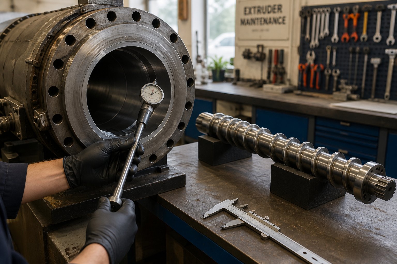
Barrel bore gauging is the standard method for tracking barrel wear. A precision bore gauge or ultrasonic thickness measurement tool inserted into the barrel ID at multiple points along its length reveals how much material has been removed from the bore surface. Measurements should be taken at consistent axial positions - typically every two to four diameters along the barrel length - and at multiple angular positions around the bore circumference to detect uneven wear patterns. Industry guidelines suggest that a barrel ID increase exceeding 0.10 mm per year warrants relining or replacement planning.
Screw flight OD measurement uses an outside diameter bar micrometer - a specialized tool with a bar that spans across the flights to contact the flight tip on each side of the screw. Davis-Standard's maintenance protocol emphasizes that the screw must first be thoroughly cleaned of all solidified plastic residue using brass tools and copper gauze - never steel wire brushes or aggressive abrasives that could damage the measurement surfaces. Measurements are recorded at regular intervals along the screw length, referenced to a tape-measured position from the drive end, creating a wear map that shows exactly where material loss is occurring.
Davis-Standard also provides diametrical wear guidelines by screw size with three threshold levels: a low number where you may notice decreased output, a medium number indicating the screw should be monitored closely with rebuild or replacement planned, and a high number meaning immediate action is needed. For barrier screws specifically, wear limits should be kept to 75% of the barrier flight clearance to maintain separation of solid and melt pools.
Trending wear data over time is where reactive maintenance transforms into predictive strategy. A single measurement tells you the current state. A series of measurements taken at regular intervals - quarterly or semi-annually for critical equipment - reveals the wear rate. That rate, plotted against operating hours, lets you predict with reasonable accuracy when a component will reach its replacement threshold. You can then schedule downtime during a planned maintenance window rather than scrambling after an unplanned failure.
A practical preventive maintenance cadence, informed by industry best practices, typically follows this pattern:
| Frequency | Tasks | Estimated Time |
|---|---|---|
| Monthly | Visual inspection of barrel exterior and heater bands; check motor current against baseline; review output rate trends; inspect feed throat cooling system | ~2 hours |
| Quarterly | Record process parameters (RPM, amps, pressures, melt temperature) and compare to baseline; check barrel zone temperatures for heater band failures; inspect thermocouples | ~4 hours |
| Semi-Annual | Pull screw for visual inspection and OD measurements; bore gauge barrel at key locations; check for scoring, corrosion, or fatigue cracks on both components | ~8 hours |
| Annual | Comprehensive dimensional audit of screw and barrel; update wear trend charts; verify machine alignment; assess rebuild vs. replace decision; inspect gearbox and drive components | ~16 hours |
The hidden costs of running worn components often dwarf the cost of proactive replacement. Consider what a worn screw and barrel actually cost you beyond the obvious: higher specific energy consumption per kilogram of output because the motor works harder to compensate for lost pumping efficiency; lower throughput rates that reduce the machine's revenue-generating capacity; increased scrap rates from inconsistent melt quality; and unpredictable product quality that erodes customer confidence. Glycon's analysis frames this as identifying the "point of diminishing returns" - the boundary beyond which process adjustments can no longer compensate for wear without measurably impacting productivity or quality. Running past that point doesn't save money. It bleeds money quietly, in ways that don't show up on a single line item but accumulate relentlessly across energy bills, yield losses, and quality complaints.
Ideally, replacement parts are already on hand or on order before a component reaches its wear limit. Tracking your wear trends gives you months of lead time to source quality replacements, schedule installation during planned downtime, and avoid the premium costs and production losses that come with emergency procurement. That forward-looking approach turns screw and barrel maintenance from a cost center into a production economics decision - one where the numbers almost always favor investing in quality components and disciplined monitoring over running to failure and hoping for the best.
Production Economics and Total Cost of Ownership
Wear trend charts and maintenance schedules protect your equipment - but they also reveal something deeper. Every data point on that wear curve carries a dollar sign. The real question isn't just when to replace a screw and barrel, but what each hour of operation actually costs when you account for everything the purchase order doesn't show. Most procurement decisions in this category focus almost entirely on the invoice price. That's a bit like choosing a car based solely on the sticker - ignoring fuel economy, insurance, maintenance intervals, and resale value.
How Screw and Barrel Selection Impacts Production Economics
Imagine two identical screw extruders running side by side on the same resin. One has a well-matched screw geometry with premium metallurgy. The other runs a lower-cost commodity screw that looked like a bargain on the purchase order. Six months in, you'll notice something striking: the "expensive" screw is producing more kilograms per hour at lower motor amperage, with tighter melt temperature distribution and fewer rejected parts. The "cheap" screw? Its clearances have opened up, output has dropped, the operator has bumped RPM and barrel temperatures to compensate, and the energy meter is spinning faster for every kilogram that comes out the die.
The purchase price of an extruder screw and barrel typically represents under 5% of the extruder's total capital cost. Yet these components govern 60% to 75% of lifetime operating economics through wear-driven downtime, energy consumption, melt quality, and replacement frequency. That's a staggering imbalance - and it's exactly why optimizing for purchase price alone is, paradoxically, the most expensive long-term strategy.
A well-matched screw design doesn't just process resin - it processes resin efficiently. The right compression ratio minimizes unnecessary shear heating. Proper barrier geometry reduces specific energy consumption (kWh per kilogram) by completing melting with less mechanical work. Optimized flight clearances maintain pumping efficiency so the motor delivers useful output rather than fighting back-leakage flow. These factors compound over thousands of operating hours, and the cumulative savings in energy, throughput, and quality consistency dwarf any difference in component purchase price.
Consider the energy penalty alone. Documented studies show a 6% to 12% increase in specific energy consumption as screw clearance widens from 0.1 mm to 0.5 mm in a 90 mm single-screw extruder. On a line consuming 50 kW and running 8,000 hours per year, even a 6% efficiency loss translates to 24,000 kWh of wasted electricity annually - real dollars that never appear on the screw's purchase order but show up relentlessly on the utility bill.
Total Cost of Ownership Framework
If you've ever justified a screw and barrel purchase based on unit price comparison alone, you're missing five-sixths of the iceberg. A comprehensive total cost of ownership (TCO) framework captures every cost element that affects your bottom line over a realistic production horizon - typically 36 months for meaningful comparison. Here's what belongs in that calculation:
- Initial purchase and lead time: The invoice price plus freight, import duties, and any expediting premiums for rush orders. Lead time matters because a four-week delivery delay on a replacement screw can force you to keep running a worn component longer, compounding all the downstream costs below.
- Installation and commissioning costs: Skilled maintenance labor for screw pull, alignment verification, thermal cycling, and break-in procedures. For a 100-150 mm extruder screw, replacement typically requires 4-8 hours of skilled labor at loaded rates that range from $85 to $150 per hour in North American facilities.
- Energy efficiency during operation: A tighter-clearance, well-designed screw converts more motor input into useful output. Over thousands of hours, even small differences in specific energy consumption create meaningful cost separation between component options.
- Achievable throughput and yield rates: Higher pumping efficiency means more saleable product per hour from the same machine. If a premium screw maintains 98% of its original output rate after 15,000 hours while a commodity screw drops to 88% after 4,000 hours, the throughput gap translates directly into revenue.
- Expected service life and wear rate: This is the multiplier that transforms all other cost categories. A screw that lasts five times longer than a cheaper alternative doesn't just save you five purchase orders - it saves you five installation events, five production interruptions, and the cumulative energy and quality penalties from running worn geometry.
- Planned vs. unplanned downtime costs: Scheduled replacement during a planned maintenance window might cost 4-8 hours of lost production. An unplanned failure that occurs mid-run - especially on a continuous extrusion line producing $1,500 to $5,000 of product per hour - can cost $12,000 to $40,000 per event in lost production before you even count scrap, restart waste, and customer delivery disruption.
When you stack these elements into a real-world comparison, the math often reverses what the purchase order suggested. A detailed TCO example from industry case data illustrates this vividly: a 75 mm twin-screw system compounding 40% glass-filled PA66 was evaluated over 36 months. The standard nitrided 4140 screw set at $8,500 averaged only 4,000 hours of service life, requiring approximately 6.6 replacement events over 36 months. The premium bimetallic CPM 10V alternative at $34,000 lasted 20,000 hours, needing roughly 1.3 replacements in the same period. Total 36-month cost including assemblies, downtime, and labor? Approximately $182,820 for the "cheap" option versus $69,160 for the premium - a 62% reduction in total operating cost by spending four times more upfront.
That kind of payback isn't universal - it depends on process severity, filler loading, and operating hours. But the principle holds across nearly every scenario: investing in higher-quality metallurgy or optimized screw geometry pays back through extended service intervals, improved process stability, and lower cumulative cost per kilogram of output. The 36-month window is long enough to capture multiple replacement cycles for commodity components while often requiring zero or one replacement for premium alternatives.
Sourcing Quality Replacement Components
TCO analysis only delivers its promised savings if the replacement components you source actually perform as specified. This is where sourcing decisions become critical. A premium alloy designation on a quotation means nothing without verified metallurgy, controlled heat treatment, and precision manufacturing behind it. When replacement time arrives - whether driven by your wear trend data or an unexpected failure - the quality of the new screw and barrel components determines whether your production economics genuinely improve or simply reset to the starting point of the same wear cycle.
What should you look for in a supply partner? Technical depth matters more than catalog breadth. A supplier who understands the relationship between screw geometry, barrel metallurgy, and application-specific demands can recommend solutions that optimize your TCO rather than simply filling an order. Davis-Standard extruder owners, operators running used single screw extruders, and teams managing diverse fleets of screw extruders all benefit from working with manufacturers who can match components to specific machine specifications and process conditions.
Suppliers like NANHAIYA offer comprehensive screw and barrel catalogs covering both extrusion and injection molding applications. Their categorized product lines - spanning barrels, screw elements, liners, and complete assemblies - serve processors, OEMs, and maintenance teams who need components precisely matched to specific machine and process requirements. This kind of organized, application-aware catalog simplifies the sourcing process considerably, especially for facilities managing multiple extruder platforms across different product lines.
Regardless of which supplier you evaluate, prioritize these sourcing fundamentals: material certifications (EN 10204 3.1 minimum) for every alloy in the assembly, documented hardness testing at multiple locations, and dimensional inspection records that confirm the component meets your machine's clearance specifications. Suppliers who can provide metallographic cross-sections for bimetallic or hardfaced components offer an additional layer of verification that surface treatments were applied correctly - not just claimed on a spec sheet.
The bottom line? Screw and barrel procurement is a production economics decision, not a purchasing transaction. Every component choice ripples through energy consumption, throughput capacity, product quality, and maintenance burden for months or years after installation. Approaching that decision with a TCO mindset - and sourcing from manufacturers who understand the full chain from metallurgy to application performance - transforms what looks like a maintenance expense into one of the highest-return investments on your production floor.
Practical Selection Framework and Next Steps
Every section of this guide has explored a different dimension of the same core truth: getting the most from your screw and barrel investment requires informed decisions at every stage - design, materials, installation, monitoring, and replacement. The difference between a plastics operation that fights its equipment and one that runs predictably comes down to how deliberately those decisions are made. Here's how to pull it all together into a repeatable, strategic approach.
Key Takeaways for Screw and Barrel Selection
Across all the geometry, metallurgy, polymer science, and maintenance practices covered in this article, five critical decision points consistently determine whether your extrusion screw barrel system delivers lasting value or becomes a recurring source of frustration and cost.
Match screw geometry to polymer and application. Semi-crystalline resins like PE and PP demand higher compression ratios and benefit from barrier designs. Amorphous polymers tolerate gentler profiles. Film lines prioritize melt temperature uniformity, pipe lines need dimensional stability, and compounding operations require intensive mixing. The screw architecture that excels in one context can underperform - or actively cause problems - in another.
Select metallurgy based on process severity. Standard nitrided steel handles unfilled commodity resins economically. Glass-filled and mineral-loaded compounds call for bimetallic barrels and tool steel screws. Corrosive polymers like PVC and fluoropolymers need alloy liners specifically engineered to resist chemical attack. Over-specifying wastes money; under-specifying wastes far more through premature failure and lost production.
Choose single vs. twin screw based on mixing requirements. If you're processing pre-compounded resins on a dedicated line, a single-screw plastic extruder delivers simplicity, lower cost, and reliable throughput. When formulation flexibility, dispersive mixing, or devolatilization drive your process, a twin-screw platform's modular design and self-wiping action justify the higher investment.
Establish clearance tolerances that balance efficiency with service life. Too-tight clearances accelerate wear. Too-loose clearances bleed pumping efficiency, raise energy consumption, and degrade melt consistency. Tracking the gap between flight OD and barrel ID over time - not just checking it once - reveals the wear rate that drives predictive replacement timing.
Evaluate total cost of ownership, not purchase price. The component invoice represents a fraction of what you'll actually spend. Energy penalties from worn geometry, throughput losses, scrap rates, and unplanned downtime accumulate relentlessly over thousands of operating hours. A screw and barrel that costs four times more upfront but lasts five times longer almost always wins the 36-month math.
Screw and barrel optimization is an ongoing process, not a one-time decision. The best-performing operations treat component selection, monitoring, and replacement as a continuous cycle of measurement, analysis, and improvement.
Building a Long-Term Component Strategy
Isolated purchase decisions - replacing a worn screw when it fails, picking a barrel from whichever supplier quotes fastest - might solve the immediate problem, but they leave long-term performance on the table. The facilities that consistently outperform their competitors in output quality, energy efficiency, and uptime share a common trait: they treat screw and barrel management as a strategic function, not a reactive chore.
What does that look like in practice? It means maintaining detailed wear records for every machine so you can predict replacement timing months in advance. It means standardizing on proven screw geometries that have demonstrated results on your specific resins and products, rather than experimenting with every new supplier's "improved" design. And it means partnering with manufacturers who bring genuine application engineering capability - suppliers who can evaluate your process conditions, recommend appropriate metallurgy, and deliver components that meet verified dimensional and material specifications.
Whether you're auditing a single problematic line or building a plant-wide component management program, the following sequence provides a structured path forward:
- Audit current screw and barrel condition. Pull screws for OD measurement, bore-gauge barrels at multiple axial and angular positions, and document current clearances against original specifications. Establish where each component sits on its wear curve - early life, mid-life, or approaching replacement threshold.
- Map polymer and process requirements. For each line, document the resin families processed, filler types and loadings, throughput targets, and the critical quality parameters that define acceptable output. This creates the requirement profile against which all component decisions should be evaluated.
- Evaluate geometry and metallurgy options. With process requirements mapped, compare your current screw designs and barrel materials against the recommendations covered in this guide. Identify mismatches - a nitrided barrel running glass-filled nylon, a general-purpose screw on a high-output film line - that represent improvement opportunities.
- Select a supply partner with application engineering capability. Look beyond price lists. The right partner understands how compression ratio interacts with your polymer's melting behavior, why your barrel liner grade matters for your specific filler package, and what clearance tolerances your process demands. NANHAIYA's product catalog offers a practical starting point for processors exploring screw and barrel options, with categorized product lines spanning single-screw barrels, twin-screw elements, liners, and complete assemblies for both extrusion and injection molding configurations.
- Implement scheduled wear monitoring. Establish a measurement cadence - quarterly or semi-annually for high-utilization lines - and track wear trends over time. Plot clearance progression against operating hours to build machine-specific wear curves. Use those curves to schedule replacements proactively, order components with standard lead times, and eliminate the premium costs and production chaos of emergency procurement.
This five-step sequence isn't a one-time project. It's a cycle. Each replacement event generates new wear data that refines your predictions. Each process change - a new resin, a higher filler loading, an increased throughput target - triggers a fresh evaluation of geometry and metallurgy. Over time, the feedback loop between measurement, analysis, and action tightens until component management becomes a quiet, well-oiled function that protects production performance almost invisibly.
Processors ready to explore specific screw and barrel configurations - whether for a single-line upgrade or a multi-machine standardization effort - can review NANHAIYA's organized product lines as a resource for matching components to machine specifications across extrusion and injection molding platforms. Their catalog structure, organized by application type and component category, simplifies the initial sourcing research that feeds into a broader TCO evaluation.
The guesswork ends when measurement begins. Armed with the selection principles, maintenance frameworks, and economic analysis covered in this guide, you have everything needed to make screw and barrel decisions that hold up - not just on the purchase order, but across every operating hour that follows.
Frequently Asked Questions About Extruder Screw and Barrel Systems
1. How do I know when my extruder screw and barrel need replacement?
Several process symptoms signal that screw and barrel wear has reached a critical point. Watch for declining output at constant RPM, which indicates excessive flight-to-barrel clearance allowing back-leakage flow. Output surging or die pressure fluctuations suggest the compression zone can no longer maintain a stable melt. Rising motor amperage without increased throughput means friction from wear is consuming energy unproductively. Discolored or degraded product points to dead spots where material stagnates. A practical rule of thumb is that flight clearance reaching four times the original tolerance warrants replacement planning. Regular bore gauging and screw OD measurement - ideally on a semi-annual schedule - lets you track wear rates and predict replacement timing months in advance, avoiding costly emergency downtime.
2. What is the difference between a single-screw and twin-screw extruder barrel system?
Single-screw extruders rely on drag flow between the barrel wall and the polymer to convey material forward. They excel at steady-state processing of pre-compounded resins, offering lower capital cost, simpler maintenance, and proven reliability for dedicated production lines. Twin-screw extruders use two intermeshing screws inside a figure-eight barrel bore. Co-rotating twin screws provide self-wiping action and superior mixing, making them the standard for compounding, reactive extrusion, and devolatilization. Counter-rotating twin screws offer positive displacement conveying with gentler shear, ideal for shear-sensitive materials like PVC. Twin-screw platforms also feature modular screw elements that can be reconfigured for different formulations. The choice depends on whether your process prioritizes simplicity and cost efficiency (single-screw) or mixing intensity and formulation flexibility (twin-screw). Many facilities run both platforms for different stages of production.
3. What materials are extruder screws and barrels made from?
The most common base material is nitrided alloy steel such as 38CrMoAlA, which provides good surface hardness and wear resistance for processing unfilled commodity resins like PE, PP, and PS. For structural strength and fatigue resistance, 42CrMo chromium-molybdenum steel is widely used as a screw core material. When processing abrasive glass-fiber-filled or mineral-loaded compounds, tool steels like SKD61 (H13) deliver superior hot hardness and wear resistance. Barrels often use bimetallic construction, where a wear-resistant alloy liner is centrifugally cast inside a structural steel shell. Advanced coatings such as tungsten carbide, chromium carbide, and nickel-based alloys extend component life further. Tungsten carbide handles extreme abrasion, while nickel-based alloys resist corrosive attack from polymers like PVC and fluoropolymers. Suppliers like NANHAIYA (nhyscrews.com/products) offer components across these metallurgy tiers for both extrusion and injection molding applications.
4. How does screw compression ratio affect plastic extrusion quality?
The compression ratio - the feed zone channel depth divided by the metering zone channel depth - determines how aggressively the screw compresses material during melting. Semi-crystalline polymers like PE and PP undergo a sharp density change when they melt, requiring higher compression ratios (typically 3:1 to 4:1) to accommodate the volume shift and ensure complete melting. Amorphous polymers like PS soften gradually and work well with lower ratios (2:1 to 2.5:1). If the compression ratio is too low for a given resin, unmelted particles may pass through to the die, causing defects. If it is too high, excessive shear generates heat that can degrade temperature-sensitive materials. Matching compression ratio to your polymer's melting behavior is one of the most impactful screw selection decisions, directly affecting melt homogeneity, energy consumption, and final product consistency.
5. What is a barrier screw and when should I use one?
A barrier screw features a secondary flight that physically separates the unmelted solid bed from the growing melt pool in the transition zone. In a standard three-zone screw, solids and melt share the same channel, which can lead to unpredictable solid bed breakup that causes output surging and temperature inconsistency. Barrier screws eliminate this by confining solids to a narrowing solids channel while melt crosses over the barrier flight into a dedicated melt channel. Two main types exist: the crossing (Maillefer) design, which works well for low-energy polymers like PS and LDPE, and the parallel (Barr) design, which offers roughly 33% more melting area and suits higher-melting-point resins like HDPE, PP, and nylon. Barrier screws are strongly recommended for high-throughput blown film, sheet extrusion, and pipe lines where melting consistency and output stability directly impact product quality.
Written by
Nanhaiya Technical Team
Zhoushan Nanhaiya Plastic Machinery Co., Ltd.
The Nanhaiya technical team supports screw and barrel manufacturing projects through application review, technical communication, custom manufacturing coordination, and production and quality control.
Discuss Your Application
Related Articles
More insights on screw barrel technology and plastics processing.

What Nobody Tells You About Screw Barrel For Plastic Machine Design
Oct 10, 2026
Learn how screw barrel for plastic machine design affects melt quality, throughput, and wear life. Covers geometry, resin matching, troubleshooting, and sourcing.
Read Article
Single Screw Extruder for Sheet: Stop Guessing, Start Specifying
Oct 9, 2026
Learn how to specify a single screw extruder for sheet production. Covers screw geometry, resin-specific processing, troubleshooting, and maintenance best practices.
Read Article
PE Pipe Extruder Machine: What Datasheets Won't Tell You
Oct 9, 2026
Learn how a PE pipe extruder machine works, key specs explained, material grade selection, maintenance tips, and buyer guidance beyond the datasheet.
Read ArticleLooking for something else?
Search by material, symptom or product and jump straight to the relevant page.
These are navigation suggestions based on keyword matching — not a quotation, not a delivery commitment, and not a substitute for engineering review. Final specification is confirmed by our engineers against your drawings and processed material.
Need help with screw barrel selection?
Share your machine model, processed material and application. Our team can help with pricing and technical support.