

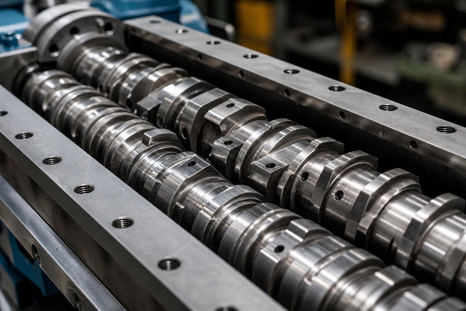
What Twin Screw Extruder Design Really Means for Engineers
Twin screw extruder design is the systematic engineering of every subsystem — screw element selection, barrel zone configuration, drive system sizing, feeding strategy, and die coupling — to transform raw materials into a precisely controlled output. It is both a discipline rooted in polymer science and fluid mechanics, and a practical workflow that translates process requirements into hardware decisions. Yet most available resources treat it as a product category overview or a manufacturer spec sheet. This article takes a different path: a design engineer's perspective that walks through the full ecosystem in one place, connecting every decision point from feed throat to die exit.
Defining Twin Screw Extruder Design as a Systems Discipline
When engineers hear "twin screw extruder design," many immediately think of the co-rotating versus counter-rotating question. That choice matters, but it represents only the opening move in a far larger game. The real discipline involves balancing shear rates, residence time distribution, mixing intensity, and throughput across an integrated system where every component influences every other.
Consider what screw configuration alone controls: mass throughput and degree of fill along the barrel, the pressure profile from feed to die, melting rate and melt homogeneity, distributive and dispersive mixing performance, temperature development from viscous dissipation, and degassing efficiency at vent ports. These outcomes emerge from how conveying elements, kneading blocks, and specialty elements interact with the material — and with the barrel thermal zones, the feeding arrangement, and the die restriction downstream. A twin screw extrusion system engineering approach recognizes that changing any single variable ripples through the entire process.
The five shear regions within the screw channel — channel, overflight, lobal pool, apex, and intermesh — each respond differently to element geometry and operating conditions. Designing effectively means understanding how pitch, kneading disc width, stagger angle, and element sequencing shape flow patterns and stress fields across all of these regions simultaneously.
Why a Holistic Design Approach Matters
Imagine selecting aggressive 90-degree kneading blocks for pigment dispersion without accounting for barrel cooling capacity in that zone. The viscous dissipation from those high-shear elements can override your temperature setpoints entirely, pushing melt temperature well above target and degrading the polymer you are trying to protect. Or picture adding a vent port for devolatilization without ensuring a proper melt seal upstream in the screw profile — the result is vent flooding and incomplete volatile removal, regardless of how much vacuum you apply.
These are not hypothetical failures. They are the predictable consequences of isolated decision-making, and they explain why so many extruder configurations underperform. Twin screw extruder design principles demand that screw geometry, barrel thermal management, feed system timing, and die back-pressure be co-optimized as a single system. The co-rotating twin screw extruder design methodology this article builds — section by section — provides exactly that end-to-end framework.
Each subsequent section addresses a critical subsystem: screw element types and their functions, the geometry and sequencing logic that governs profile performance, barrel segment design and zone configuration, L/D ratio selection, mixing strategies, computational tools, application-specific configurations, and troubleshooting. Together, they form a complete reference for engineers learning how to design a twin screw extruder or optimize an existing one.
True twin screw extruder design is the co-optimization of every subsystem from feed throat to die exit — screw elements, barrel zones, drive capacity, feeding strategy, and die geometry must be engineered as one integrated system, not as independent choices.
The subsystem that anchors this entire framework is the screw profile itself — the modular assembly of elements that directly determines how material is conveyed, melted, mixed, devolatilized, and pressurized. Understanding each element type and its functional role is the essential first step.
Every Major Twin Screw Extruder Screw Element Type Explained
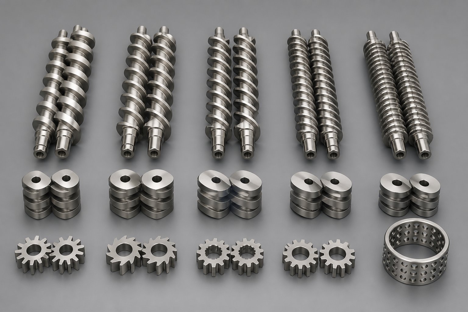
Screw elements are modular, interchangeable components that slide onto a splined shaft inside the barrel, and each one features a specific geometry — defined by its pitch, disc angle, or tooth pattern — that produces a targeted processing effect such as conveying, melting, mixing, devolatilizing, or pressurizing the material. Change a single element on the shaft, and you change how the polymer flows, how much shear it receives, and how long it stays inside the barrel. That level of granular control is exactly why understanding twin screw extruder screw element types is the essential foundation for any profile optimization effort.
Think of it this way: the extruder barrel provides the housing and thermal environment, but the screw elements are the engine. A surprisingly small family of element categories — conveying segments, kneading blocks, and specialty mixers — combines into nearly infinite configurations, much like an alphabet forming words. The sections below break down every major type you will encounter, what it does, and where it belongs.
Conveying Elements and Their Pitch Variations
Conveying elements are the workhorses of any screw profile. They feature helical flights wrapped around a cylindrical core, and their primary job is straightforward: transport material through the barrel. The defining parameter is pitch — the axial distance the flight travels in one full revolution, often expressed as a multiple of the screw diameter (D).
Why does pitch matter so much? Because it directly governs how fast material moves, how full the barrel channel becomes, and how much pressure builds at any given point. Here is how the three standard pitch ranges compare:
- Large pitch (1.5D to 2D): Moves high volumes of material quickly, keeps fill level low, and minimizes residence time. You will find these in the feed zone, where their open volume pulls bulk material away from the feed throat and displaces entrapped air back toward the hopper. They are also positioned downstream of side feeders to accept incoming fillers without choking.
- Medium pitch (approximately 1D): Balances conveying capacity with moderate fill, making it the go-to choice for transitional sections between processing zones.
- Small pitch (0.4D to 0.5D): Restricts forward flow, increases barrel fill, and builds pressure. Engineers rely on tight-pitch elements in the metering zone near the die to deliver stable, consistent melt pressure and improve homogeneity.
Pitch selection is not just about speed — it shapes the pressure profile along the entire screw length. Large-pitch elements create starved, low-pressure zones essential for venting, while small-pitch elements generate the forward thrust needed to push melt through a restrictive die. Getting this gradient right is one of the first decisions in any twin screw extruder design.
Kneading Blocks and Their Role in Mixing and Melting
If conveying elements are the legs of your screw profile, kneading blocks are its hands — they do the heavy lifting of melting, shearing, and blending. A kneading block consists of a stack of elliptical discs mounted on the shaft at offset angles relative to one another. That offset, called the stagger angle, is the single most influential parameter controlling how aggressively the block mixes.
Industry nomenclature follows a consistent pattern. A designation like KB45/5/30 tells you three things at a glance: a 45-degree stagger angle between successive discs, five discs in the stack, and a total element length of 30 mm. With the kneading block stagger angle explained this way, you can quickly decode any manufacturer's catalog.
Three stagger orientations define the kneading block family:
- Forward-staggered (e.g., 30° or 45°): Provides moderate mixing while still conveying material downstream. Less aggressive, these are suited for initial melting stages where the polymer is transitioning from solid to melt.
- Neutral (90° stagger): Produces zero net forward conveying. Material dwells in the block longer, maximizing shear input — a powerful tool for breaking up pigment agglomerates or forcing complete melting of crystalline polymers.
- Reverse-staggered (left-handed): Actively pushes material backward, creating the highest restriction, longest local residence time, and most intense mixing. Often used to form a melt seal ahead of vacuum vent zones.
Disc width adds another layer of control. Wider discs force more polymer over the tip clearance and act more like a plow, delivering intense but less frequent shear events. Narrower discs slice through the melt with less energy input per pass, providing more frequent but gentler mixing. Engineers consider both stagger angle and disc width together when fine-tuning a kneading section — a relationship explored in depth in the next chapter.
Reverse Elements, Toothed Mixers, and Specialty Elements
Beyond standard conveying and kneading geometries, several specialty elements fill niche but critical roles in twin screw extruder design.
A reverse-flight conveying element — sometimes labeled with an "L" suffix indicating left-handed rotation — actively opposes the flow direction. Instead of pushing material forward, it creates localized back-pressure that forms a melt seal. You will typically find a reverse flight element in a twin screw extruder positioned upstream of vent ports or sandwiched between kneading block sections to intensify fill and shear in a targeted zone. Without these elements, effective devolatilization is nearly impossible.
Toothed mixing elements (ZME, TME, SME) use rows of interlocking teeth rather than continuous flights or discs. The toothed mixing element function in twin screw extrusion is primarily distributive — splitting and recombining melt streams repeatedly without imparting heavy shear. This makes them ideal for applications where you need spatial uniformity (spreading an additive evenly through the matrix) without the risk of thermal degradation from excessive energy input. TME designs were among the earliest tooth-type elements and offer excellent lateral mixing, while ZME variants add a slight reverse-conveying action with self-cleaning geometry. SME elements take yet another approach: essentially conveying elements with machined grooves that allow controlled leakage flow, combining forward transport with axial distribution.
Blister rings are short, cylindrical discs with minimal clearance to the barrel wall. They create a thin-film melt seal that separates pressure zones — essential for effective devolatilization, where a significant pressure drop at the vent opening is needed to flash off volatiles. Think of them as one-element dams that keep upstream and downstream zones functionally isolated.
The table below consolidates every major element type into a quick-reference format that engineers can return to whenever assembling or modifying a screw profile:
| Element Type | Geometry Description | Primary Function | Typical Screw Zone Placement |
|---|---|---|---|
| Large-pitch conveying | Deep helical flights, 1.5D–2D pitch | High-volume material transport, low fill | Feed zone, downstream of side feeders |
| Medium-pitch conveying | Standard helical flights, ~1D pitch | Balanced conveying and moderate fill | Transition sections between zones |
| Small-pitch conveying | Shallow helical flights, 0.4D–0.5D pitch | Pressure buildup, improved melt homogeneity | Metering / die discharge zone |
| Reverse-flight conveying | Left-handed helical flights | Back-pressure generation, melt sealing | Upstream of vent ports, between kneading sections |
| Forward kneading block (30°–45°) | Staggered elliptical discs, right-handed offset | Moderate dispersive and distributive mixing | Melting zone, initial mixing zone |
| Neutral kneading block (90°) | Staggered elliptical discs, 90° offset | Maximum shear, zero net conveying | Intensive mixing / dispersion zone |
| Reverse kneading block | Staggered elliptical discs, left-handed offset | Maximum restriction, melt seal creation | Pre-vent seal zone, high-shear mixing zone |
| Toothed mixing (ZME / TME / SME) | Rows of interlocking teeth or grooved flights | Distributive mixing with low shear | Post-melting mixing zone, before compression |
| Blister ring | Short cylindrical disc, tight barrel clearance | Melt seal, pressure zone separation | Immediately upstream of vent or vacuum port |
Each of these elements is a precisely engineered tool, but its performance depends entirely on context — specifically, where it sits relative to its neighbors on the shaft. A 90-degree kneading block that delivers perfect pigment dispersion in one position can cause torque overloads or thermal degradation if placed too early in the profile. That sequencing logic — how stagger angles, disc widths, and element order interact to create the screw's overall pressure and shear landscape — is where profile design moves from component selection into true engineering strategy.
Screw Element Geometry and Sequencing Logic
Knowing what each element does is one thing. Knowing how elements behave differently depending on their geometry — and how they interact when placed next to each other on the shaft — is where twin screw extruder design separates competent engineers from those still chasing trial-and-error solutions. Two kneading blocks with identical disc counts but different stagger angles can produce wildly different mixing outcomes. Two screw profiles with identical element inventories arranged in different sequences can yield completely different pressure profiles, fill patterns, and melt temperatures. The geometry and order matter as much as the element choice itself.
How Stagger Angle Controls Shear and Conveying
Picture a stack of elliptical discs on a shaft. If each disc is offset from the previous one by a small angle, the resulting helix still pushes material forward — just with more turbulence than a smooth flight would. Increase that offset toward 90 degrees, and the forward-pushing helix flattens into something closer to a series of independent paddles. That geometric continuum is the heart of any kneading disc stagger angle selection guide.
Here is how the three primary stagger positions perform in practice:
- 30° stagger: Retains strong forward conveying action while introducing moderate shear and elongational mixing. Material passes through quickly, making this angle ideal for gentle initial melting of heat-sensitive polymers or soft blending of pre-melted components. Think of it as a conveying element that also kneads lightly.
- 60° stagger: Strikes a balance — forward conveying drops significantly while shear intensity rises. This mid-range angle works well for general-purpose compounding where you need real mixing energy without the thermal penalty of fully neutral elements. Many engineers default here when a single kneading section must handle both melting and moderate dispersion.
- 90° stagger: Produces zero net forward conveying. Each disc acts independently, forcing the material to dwell and experience maximum shear stress. This is the configuration for aggressive dispersion tasks — breaking apart pigment agglomerates, deagglomerating mineral fillers, or forcing reluctant polymer blends past their interfacial resistance. The trade-off? Residence time spikes locally, and viscous dissipation can push melt temperatures well above barrel setpoints.
As NC State Extension research confirms, forward kneading elements are less aggressive, neutral kneading elements increase residence time because they only impart energy without conveying, and reverse kneading blocks create maximum restriction by pushing material backward. The stagger angle is not merely a mixing dial — it simultaneously controls local fill level, energy input, and pressure consumption along the screw.
Narrow vs. Wide Kneading Disc Trade-Offs
Stagger angle gets most of the attention, but disc width quietly shapes mixing quality just as much. Imagine two kneading blocks with identical stagger angles and total element lengths — one built from five wide discs, the other from seven narrow ones. Their mixing behavior differs fundamentally.
Wide discs expose the polymer to fewer but more intense shear events. Each disc tip forces a larger volume of melt over the flight clearance in a single pass, generating high local stress — exactly what dispersive mixing demands. However, fewer discs per unit length means fewer apex regions where the intermeshing screws squeeze material between them. The result is powerful but spatially concentrated energy input.
Narrow discs flip this relationship. More discs pack into the same axial length, multiplying the number of apex exposures the material encounters. Each individual event applies less stress, but the cumulative effect is a higher frequency of gentle mixing actions spread more evenly along the element. This is the narrow vs. wide kneading disc trade-off in its simplest form: narrow discs favor distributive mixing and thermal gentleness, while wide discs favor dispersive intensity at the cost of higher local melt temperature rise.
For a practical decision framework, consider the material's sensitivity:
- Shear-sensitive polymers or APIs: Favor narrow discs to distribute energy input and minimize peak temperatures.
- Tough agglomerates or high-viscosity blends: Favor wide discs to exceed cohesive forces and break down resistant structures.
- Formulations needing both: Use wide discs early in the kneading section for initial breakdown, then transition to narrow discs for spatial homogenization — a sequencing principle that connects directly to how elements are ordered on the shaft.
Element Sequencing Strategy and Pressure Profile Management
Every element on the shaft either generates pressure, consumes it, or actively opposes it. The sequence in which you arrange these elements creates the extruder's pressure profile — and that profile governs fill level, mixing intensity, devolatilization capability, and die output stability. Screw element sequencing in a twin screw extruder is, fundamentally, pressure profile management.
Forward conveying elements build pressure by pushing material toward the die. Kneading blocks consume that pressure through their mixing action — the more aggressive the stagger angle, the greater the pressure drop. Reverse elements and blister rings actively oppose forward flow, creating sharp pressure spikes that form melt seals. The interplay between these "permissive" zones (where material flows freely) and "restrictive" zones (where flow is deliberately impeded) defines the functional architecture of the entire profile.
Consider what happens when you place a 90-degree kneading block immediately downstream of the feed zone without sufficient conveying length ahead of it. The kneading block consumes pressure faster than the short conveying section can generate it. Fill drops, the kneading block starves, and mixing performance collapses — despite using the most aggressive element available. Sequencing errors like this are among the most common and most misdiagnosed performance problems in twin screw extrusion.
When assembling or modifying a modular screw profile, the following sequencing principles will keep your pressure profile balanced and your process stable:
- Start with large-pitch conveying elements in the feed zone to maximize intake capacity and prevent feed-throat bridging.
- Transition pitch gradually — step from large to medium pitch before introducing the first kneading section, building enough upstream pressure to keep kneading blocks properly filled.
- Place the most aggressive kneading blocks (90° or reverse) only after sufficient conveying length has established adequate fill and pressure reserve.
- Follow each restrictive zone with a conveying section to re-establish forward flow and relieve the pressure spike before the next functional zone begins.
- Position reverse elements or blister rings immediately upstream of vent ports to create a melt seal that prevents melt from flooding back into the vent opening.
- Ensure vent zones use large-pitch conveying elements to maintain low fill and create the free surface area volatiles need to escape.
- End the profile with progressively tighter-pitch conveying elements to build smooth, consistent die pressure without introducing additional shear.
- Never stack multiple aggressive restrictive elements in series without intervening conveying segments — doing so creates excessive back-pressure that overloads torque and degrades material.
These principles produce an alternating pattern of pressure buildup and pressure consumption along the screw length — a sawtooth-like pressure profile that engineers can visualize and adjust zone by zone. Each peak corresponds to a restrictive element or melt seal. Each valley corresponds to a permissive conveying zone. The height, spacing, and number of those peaks directly shape residence time distribution, specific energy input, and ultimately product quality.
Screw geometry and sequencing define the internal flow landscape, but they do not operate in isolation. The barrel surrounding those elements — its thermal zones, liner materials, vent port locations, and side-feeder openings — must be configured to complement the pressure and shear profile the screw creates. That barrel-side design is the other half of the equation.
Barrel Segment Design and Zone Configuration
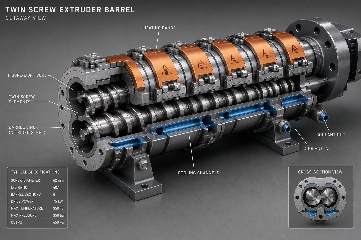
Engineers spend hours optimizing screw profiles — swapping kneading blocks, adjusting stagger angles, fine-tuning pitch transitions — yet many treat the barrel as a passive steel tube that simply houses the screws. That is a costly misconception. The barrel provides the thermal boundary conditions, the wear interface, and the physical openings through which material enters, exits, and degasses. Every decision made on the screw side depends on the barrel doing its job correctly. When twin screw extruder barrel zone configuration is mismatched with the screw profile, even the most elegant element sequence underperforms.
Heating and Cooling Zone Configuration
A twin screw extruder barrel is divided into discrete, independently controlled thermal zones — typically one per barrel segment, with commercial machines ranging from 6 to 14 zones depending on the overall L/D ratio. Each zone has its own heater bands (electric cartridge or cast aluminum), its own cooling circuit (water or oil), and its own temperature sensor feeding a PID controller. This independence matters because every section of the screw performs a fundamentally different function, and those functions demand different thermal environments.
The feed zone runs coolest — often water-cooled to ambient or slightly above — to prevent pellets from softening prematurely and losing the frictional grip needed for solids conveying. As JWELL's engineering team explains, excessive heat in the feed zone causes pellets to slip against the barrel wall rather than being pushed forward, producing output fluctuations and potential surging. Downstream zones ramp progressively higher, tracking the polymer's melting and mixing requirements, until the final zones near the die stabilize at the target melt delivery temperature.
Here is where many engineers get tripped up: the barrel temperature setpoint is not the melt temperature. Actual melt temperature typically exceeds the final barrel zone setpoint by 10 to 30 degrees Celsius in commercial operations. That gap widens with higher screw speeds, more aggressive kneading configurations, and higher-viscosity polymers — all of which generate more viscous dissipation. In high-shear zones containing 90-degree or reverse kneading blocks, the screw can pump so much mechanical energy into the melt that barrel cooling cannot extract it fast enough. You set the barrel to 220 degrees Celsius, but the melt running past that zone may reach 250 or beyond.
This reality has direct implications for zone configuration. Engineers should:
- Align cooling-intensive zones with the screw's most aggressive mixing sections — wherever 90-degree kneading blocks or reverse elements sit, the corresponding barrel zone must have robust cooling capacity, not just heating capability.
- Avoid setting all zones to the same temperature — a flat barrel profile ignores the functional differences between conveying, melting, mixing, and metering sections, and forces the PID controllers to fight the screw's own heat generation.
- Monitor actual melt temperature with an immersion thermocouple at the die adapter, not just barrel wall readings. The barrel thermocouple measures steel temperature, not polymer temperature — a distinction that separates data-driven optimization from guesswork.
Thermal responsiveness also varies with barrel construction. Thick-walled barrel segments have more thermal mass, meaning they respond slowly to setpoint changes and resist rapid cooling — a challenge during startups and grade transitions. Thinner-walled or modular barrel designs improve responsiveness but may sacrifice some mechanical rigidity. Matching zone count and zone length to the screw profile's functional architecture ensures that each processing zone receives the thermal support it actually needs.
Barrel Liner Materials and Wear Resistance
Inside every barrel segment, the bore surface endures constant abrasion from rotating screw elements, corrosive polymer degradation products, and — in filled compounds — relentless attack from glass fibers, mineral particles, and ceramic fillers. Barrel liner material selection for extrusion directly determines service life, maintenance costs, and product contamination risk. Choose the wrong liner, and you could be replacing barrel segments every few months rather than every few years.
Three liner categories cover the majority of applications:
- Nitrided steel provides a hardened surface layer on standard tool steel barrels, typically reaching 55 to 65 HRC. It is cost-effective and well-suited for general-purpose compounding of unfilled or lightly filled polymers. However, nitrided layers are relatively thin (0.3 to 0.7 mm), and once worn through, the softer substrate beneath erodes rapidly.
- Bimetallic liners use a centrifugally cast alloy lining — commonly nickel-boron or iron-boron based — metallurgically bonded inside a standard steel barrel shell. These liners achieve hardness in the 58 to 70 HRC range with much greater depth than nitriding, offering significantly longer life in abrasive applications such as glass-fiber-reinforced compounds, calcium carbonate-filled masterbatch, and mineral-loaded engineering plastics.
- Tungsten carbide inserts represent the extreme end of the wear-resistance spectrum. Reserved for highly abrasive formulations — think ceramic-filled polymers, metal powder injection molding feedstocks, or recycled material streams with heavy contamination — these inserts can last several times longer than bimetallic liners but at substantially higher cost.
One factor that engineers frequently overlook is how liner selection interacts with screw element metallurgy. When dissimilar metals rotate in contact, galvanic corrosion and adhesive wear can accelerate degradation on both surfaces. Pairing a soft screw material with a much harder barrel liner can concentrate wear on the screw elements, shortening their life. Conversely, a very hard screw element running inside a softer barrel bore wears the barrel instead. The goal is a complementary hardness pairing — typically with the barrel liner slightly harder than the screw element tips — to distribute wear evenly and maximize the service interval for both components.
The table below provides a quick-reference comparison when evaluating the bimetallic barrel liner vs. nitrided steel decision and beyond:
| Liner Material | Hardness Range (HRC) | Best-Suited Applications | Relative Cost |
|---|---|---|---|
| Nitrided steel | 55–65 | Unfilled or lightly filled polymers, general-purpose compounding | Low |
| Bimetallic (Ni-B / Fe-B alloy) | 58–70 | Glass fiber, mineral fillers, calcium carbonate, abrasive masterbatch | Moderate |
| Tungsten carbide insert | 72–78 | Ceramic-filled polymers, metal powder feedstocks, extreme-wear recycling | High |
Vent Port and Side-Feeder Placement Strategy
Vent ports and side-feeder openings are not afterthoughts — they are precision-placed features whose positions must align with specific conditions inside the screw profile. Get the placement wrong, and even the best screw geometry cannot compensate.
Vent port placement in twin screw extruder design follows one non-negotiable rule: every vent — whether atmospheric or vacuum — must be positioned downstream of a melt seal. That seal, created by reverse-flight elements, reverse kneading blocks, or blister rings, prevents upstream melt from flooding into the vent opening. As Plastics Technology details, stable vent operation requires a low degree of fill within the screws at the vent opening and a filled-screw melt seal upstream of it. If the melt seal is too weak or positioned too far from the vent, rising back-pressure from downstream screen packs or die restriction can push the backup length of filled screw right into the vent opening — flooding it with polymer and shutting down devolatilization entirely.
Vacuum vents demand particular attention. They are typically positioned near the end of the barrel and operate at 100 to 300 mbar to flash off residual moisture, monomers, or volatile byproducts. The screw section beneath the vent must use large-pitch conveying elements to keep fill levels low, exposing thin melt layers with maximum free surface area for mass transfer. Insufficient free surface means volatiles stay trapped inside the melt regardless of vacuum intensity.
Side-feeder barrel openings follow a complementary logic. They must align with starve-fed conveying zones — sections where the screw is only partially filled — so incoming fillers or additives can enter without being blocked by a pressurized melt column. Large-pitch conveying elements directly downstream of the feeder pull material away from the opening and prevent backup into the feeder barrel. Atmospheric vents positioned near side feeders serve a critical secondary function: they release the entrained air that arrives with low-bulk-density powders like talc or fumed silica. The lower the filler's bulk density, the greater the volume of air that enters through the side feeder and the more vent area required to handle it without blowing fines out of the opening.
Getting barrel openings right is fundamentally a coordination exercise between the barrel's physical layout and the screw profile's pressure and fill map. Every vent port and side-feeder position should be verified against the screw's pressure profile to ensure it sits in the correct flow regime — a step that becomes far more efficient when guided by the L/D ratio framework and its influence on how many functional zones the extruder can support.
How L/D Ratio Shapes Twin Screw Extruder Processing Performance
The number of barrel segments you bolt together determines far more than extruder length. It sets the upper limit on how many functional zones — melting, mixing, devolatilizing, side feeding, metering — can physically fit between the feed throat and the die. The length-to-diameter ratio, universally abbreviated as L/D, is the single parameter that governs this capacity. Yet most discussions of how L/D ratio affects extrusion performance stop at "longer equals better mixing," which is dangerously incomplete. Longer barrels also mean longer residence time, higher energy consumption, and greater exposure to thermal degradation. The real engineering question is not "how long?" but "how long for this specific process?"
Standard L/D Ratios and Their Processing Implications
Commercial twin screw extruders cluster around five standard L/D ratios, each representing a distinct balance between processing capability and practical trade-offs. Think of these as platforms — each one unlocking a different set of design possibilities:
- 24:1: The shortest configuration commonly available, typically reserved for laboratory-scale machines or simple blending tasks with minimal processing demands. At this length, you get a feed zone, one melting/mixing section, and a short metering zone — essentially three functional zones with little room for venting or downstream addition.
- 32:1: The workhorse ratio for straightforward compounding operations. It accommodates a proper feed zone, a melting section, one or two mixing zones, a single atmospheric vent, and a metering zone. For unfilled polymer blends or lightly loaded masterbatch, 32:1 often provides sufficient mixing without excessive residence time. Industry experience confirms this as the most commonly used range for general-purpose applications.
- 40:1: Adds meaningful barrel real estate for a second kneading zone, a side-feeder port for downstream filler introduction, and a vacuum vent for devolatilization. This ratio is increasingly considered the standard for the best L/D ratio for polymer compounding extruder setups processing glass-fiber-reinforced or mineral-filled engineering plastics, where the added length separates melting from filler incorporation.
- 48:1: Opens the door to complex, multi-stage processes. Engineers gain room for multiple injection points, two or more vacuum vents, extended distributive mixing sections, and longer residence time for reactive extrusion chemistries. Processes like grafting reactions or moisture-crosslinkable polyethylene compounding frequently demand this length to allow sufficient reaction time and thorough devolatilization.
- 52:1: The extreme end of commercial configurations. These machines are designed for processes that stack multiple sequential operations — melting, reactive modification, multiple-stage devolatilization, and final mixing — into a single pass. The additional length enables four or more independent processing zones, but each added barrel segment increases the total residence time and the cumulative energy input the material absorbs.
That last point deserves emphasis. Every barrel segment you add extends the time your polymer spends at elevated temperature under shear. For thermally stable engineering resins, this is manageable. For heat-sensitive materials — PVC, certain biopolymers, temperature-sensitive pharmaceutical compounds — unnecessary barrel length can degrade the very product you are trying to make. Longer is not always better. The right L/D ratio is the shortest one that still provides enough functional zones for your specific process.
Matching L/D Ratio to Application Complexity
How do you determine which ratio your application actually needs? Start by listing every functional zone the process demands, then count the barrel segments required to house them. A simple color concentrate blend might need only feed, melt, mix, and meter — four zones that fit comfortably within 32:1. A devolatilization-heavy reactive extrusion process might require feed, melt, react, vent one, remix, side feed filler, mix, vent two, and meter — nine or more functional zones pushing you toward 48:1 or beyond.
This twin screw extruder L/D ratio selection guide becomes more nuanced when you factor in throughput. At constant screw speed, adding restrictive elements to fill those extra barrel segments reduces specific throughput — kilograms per hour per RPM. The additional kneading blocks and reverse elements that justify a longer barrel also create more flow resistance, meaning you either accept lower throughput or increase screw speed to compensate. Higher screw speed raises viscous dissipation, which raises melt temperature, which may push you back toward the thermal degradation risk you were trying to avoid.
The practical solution is iterative: define the minimum number of functional zones required, select the shortest L/D that accommodates them, then verify — through simulation or trial — that throughput and melt temperature targets can be met simultaneously. Processing guidelines generally recommend shorter ratios (20:1 to 28:1) for thermally sensitive materials needing minimal residence time, medium ratios (28:1 to 36:1) for general compounding and fiber reinforcement, and longer ratios (36:1 to 48:1 and above) for devolatilization, reactive extrusion, or highly filled systems requiring extended mixing and multiple injection stages.
One subtle but important interaction: L/D ratio constrains where side feeders and vent ports can be placed, which in turn constrains the screw profile. A 32:1 barrel simply does not have room for both a side feeder and a downstream vacuum vent with proper melt seals before each. If your formulation requires downstream filler addition and devolatilization, 40:1 becomes the practical minimum — not because of mixing intensity, but because of physical space for barrel openings.
Five Key Mass Transfer Regions in the Twin Screw Extruder Channel
L/D ratio does not just add length — it changes the relative contribution of distinct mixing regions within the screw channel. Understanding these mass transfer regions in twin screw extruder channel geometry explains why identical L/D ratios can produce dramatically different mixing outcomes depending on screw speed, fill level, and element selection.
As American Leistritz research documented, every twin screw extruder — regardless of rotation direction or intermesh level — contains five distinct shear regions. Each region generates a different type and intensity of mixing action. Ranked from highest to lowest typical mixing contribution for co-rotating intermeshing twin screws, these regions are:
- Intermesh region: Where the two screws overlap and material is wiped from one screw to the other. In co-rotating machines, the opposing surface velocities at the intermesh create intense shear as material is transferred between screws. This is the most powerful mixing region and the one that distinguishes twin screw performance from single screw.
- Apex region: The zone where the interaction from the second screw influences the material on the first. Material is squeezed between the approaching lobes of the two screws, generating high-stress mixing events that are particularly effective at breaking up agglomerates and forcing interfacial contact in polymer blends.
- Overflight region: The narrow gap between the screw flight tip and the barrel wall. Shear rate here can be up to 50 times higher than in the screw channel, creating a thin-film, high-intensity mixing zone. Every revolution forces a portion of material through this gap, contributing dispersive mixing with every screw turn.
- Extensional (lobal pool) region: As material is compressed entering the overflight zone, it undergoes elongational deformation — stretching rather than simple sliding. This extensional shear is particularly effective at breaking up droplets in immiscible blends and deagglomerating fillers, because elongational flows generate higher stress at lower total energy input compared to simple shear.
- Channel region: The open volume between adjacent flights and the barrel wall. Mixing here resembles what happens inside a single screw extruder — relatively low shear, dominated by drag flow. It is the least intensive mixing region but occupies the largest volume, which is why it tends to dominate overall mixing character at high fill levels.
Here is the critical connection to L/D and screw design: the four high-shear regions — intermesh, apex, overflight, and extensional — are largely independent of how full the screw channel is. They activate every time the screws rotate, regardless of throughput. The channel region, by contrast, scales directly with fill level. At a given screw speed, increasing throughput raises the channel's relative contribution — and since it is the lowest-intensity region, overall mixing quality decreases. Decrease throughput at the same speed, and the four high-intensity regions dominate more, delivering better mixing.
This principle has direct implications for L/D selection. A longer barrel with more kneading sections multiplies the number of times material encounters these high-shear regions. But if you simultaneously increase throughput to fill the added length, the low-shear channel mixing can overshadow the gains. The most effective use of additional L/D is adding more high-shear elements — kneading blocks, mixing elements — that activate the intermesh, apex, and overflight regions, rather than simply adding conveying length that only amplifies channel-region residence time.
These mass transfer regions do not just determine how thoroughly material is mixed — they determine what kind of mixing occurs. Dispersive or distributive. Stress-dominated or redistribution-dominated. And that distinction is exactly what the next section addresses: how to engineer the right balance of dispersive and distributive mixing within a single screw profile.
Dispersive and Distributive Mixing Strategies
A compound can look perfectly blended at a glance yet fail in service because the additive particles were evenly spread but never broken down to their functional size. Or the opposite: agglomerates were shattered into fine particles that clumped together in one region of the matrix while the rest of the polymer went untouched. These two failure modes correspond directly to the two fundamental mixing mechanisms every twin screw extruder must deliver — and confusing one for the other is one of the most common screw profile design mistakes engineers make.
Understanding the distinction between dispersive vs. distributive mixing in a twin screw extruder is not academic. It determines which screw elements you choose, where you place them, and how aggressively you configure them. Get the balance wrong, and you either over-shear the polymer chasing dispersion that was never needed, or you spread undispersed agglomerates uniformly throughout the part — producing consistent but consistently poor quality.
Dispersive Mixing and How to Achieve It
Dispersive mixing is the breakup of agglomerates, droplets, or phase domains by applying stress that exceeds the cohesive or interfacial forces holding them together. Imagine a clump of carbon black aggregates bound by weak van der Waals forces. To separate those aggregates, the local shear stress imposed by the screw must overcome those binding forces — otherwise the clump simply tumbles through the extruder intact, no matter how many times it circulates.
The mechanism is fundamentally stress-driven. As Paderborn University research demonstrated through 3D CFD flow simulations with particle tracking, the maximum shear stress each particle experiences along its path — and the integral of shear stress over residence time — are the two decisive parameters for evaluating dispersive mixing effectiveness. High peak stress breaks agglomerates through rupture, while sustained moderate stress erodes them gradually. Both pathways require screw elements that generate intense localized shear fields.
So how do you achieve dispersive mixing in extrusion? The answer lies in element geometry and clearance:
- Wide kneading discs at 60° or 90° stagger are the primary dispersive workhorses. Wide discs force large volumes of polymer over the flight tip in a plowing action, creating high shear stress as the melt is compressed through the narrow gap between disc tip and barrel wall. A 90° stagger eliminates forward conveying entirely, increasing local residence time and the number of high-stress exposures each particle receives.
- Narrow screw-to-barrel clearances amplify shear rate in the overflight region. Shear rate in this gap scales inversely with clearance height — tighter gaps mean higher velocity gradients and greater stress on entrained particles. This is why worn barrels with enlarged clearances often produce inferior dispersion even with identical screw profiles.
- Reverse kneading blocks push material backward, creating a pressurized, fully filled zone that forces every particle through the high-shear overflight and intermesh regions multiple times before escaping downstream.
The Paderborn study also revealed that toothed mixing elements (ZME) generate surprisingly high maximum shear stresses — in some configurations exceeding those of kneading blocks — because of the flow acceleration around their tooth geometry. This challenges the common assumption that toothed elements are purely distributive, and reinforces why element selection for dispersive mixing should be guided by flow analysis rather than tradition alone.
Distributive Mixing and Element Design for Spatial Uniformity
Distributive mixing operates on a completely different principle. Rather than breaking things apart, it rearranges them — splitting, reorienting, and recombining flow streams to spread minor components uniformly throughout the polymer matrix without requiring high stress. Picture folding dough: each fold doubles the number of layers and halves the striation thickness, progressively improving spatial homogeneity without crushing the ingredients.
In a twin screw extruder, distributive mixing relies on elements that divide and recombine the melt stream as many times as possible per unit screw length. The goal is maximizing the number of reorientation events while minimizing energy input per event. As Kenneth Russell explains, narrow kneading discs slice through the polymer in a scissoring action — dividing the melt with one disc and covering it with the next — which promotes distributive mixing by essentially stirring the polymer and additives rather than shearing them.
The distributive mixing element selection guide breaks down into three primary categories:
- Narrow kneading discs (forward stagger, 30°–45°): Maximize the number of apex exposures per unit length. Each narrow disc provides a gentle folding and reorienting action, and packing more discs into the same element length multiplies these events. Forward stagger maintains some conveying action, preventing the excessive dwell time that raises melt temperature.
- Toothed mixing elements (ZME / TME): Rows of interlocking teeth divide the melt stream into multiple sub-streams that recombine repeatedly as material passes through successive tooth rows. The Paderborn CFD study confirmed the ZME as the most effective element for distributive mixing, consistently achieving the lowest mixing index (MQ) values — meaning the most uniform particle distribution — across all tested rotation speeds, materials, and extruder sizes.
- Screw mixing elements (SME) with slotted flights: Standard conveying elements modified with machined grooves or slots that allow controlled leakage flow between flight channels. Material crosses from one channel to the adjacent one, creating lateral redistribution while maintaining forward conveyance. These are particularly useful in the final metering section, where you want to homogenize without adding significant shear or pressure drop.
Gear-type mixers represent yet another approach, using intermeshing helical gears to split flow into thin layers — effective for blending components with large viscosity differences, such as incorporating low-viscosity additives into high-viscosity matrices.
Balancing Dispersive and Distributive Mixing in a Single Profile
Real formulations almost never need just one type of mixing. Consider a carbon-black-filled polyethylene compound. The carbon black arrives as agglomerates that must first be broken down to their aggregate size — a dispersive task requiring high shear stress. But once dispersed, those fine aggregates must be spread uniformly throughout the polyethylene matrix — a distributive task requiring gentle, high-frequency reorientation. Skip the dispersion step, and you get evenly spaced clumps. Skip the distribution step, and you get well-dispersed particles concentrated in one region of the melt. Neither outcome is acceptable.
This dual requirement drives a fundamental sequencing principle for balancing dispersive and distributive mixing in a screw profile: dispersive elements should generally precede distributive elements. The logic is straightforward — you must break agglomerates apart before you can spread the resulting fine particles uniformly. Placing distributive elements first simply redistributes intact agglomerates, wasting barrel length without solving the underlying problem.
A practical screw profile for a heavily filled compound might follow this pattern:
- Dispersive zone first: Wide kneading discs at 60° progressing to 90° stagger, followed by a reverse kneading block or reverse element to form a melt seal. This zone delivers the high shear stress needed to rupture agglomerates and deagglomerate filler particles.
- Distributive zone second: Narrow kneading discs at 30°–45° forward stagger, transitioning into toothed mixing elements (ZME or TME). This zone redistributes the now-dispersed particles uniformly throughout the matrix without re-introducing excessive thermal energy.
- Conveying elements between zones: Forward conveying segments separate the two mixing zones, allowing the melt to relax, reducing localized temperature spikes, and re-establishing the pressure profile before the next functional section.
For a quick-reference summary, here are the element choices matched to each mixing objective:
- For dispersive mixing: Wide kneading discs (60°–90° stagger), reverse kneading blocks, reverse-flight elements, and — where flow analysis supports it — toothed mixing elements at high rotation speeds.
- For distributive mixing: Narrow kneading discs (30°–45° forward stagger), toothed mixing elements (ZME / TME), screw mixing elements with slotted flights, and gear-type mixers.
Over-reliance on dispersive mixing raises melt temperature and risks polymer degradation — every high-shear element you add converts mechanical energy into heat, so use only the dispersive intensity your formulation actually requires and handle the rest with gentler distributive elements.
Russell's practical experience reinforces this point: mixing sections work more efficiently and more gently when they maintain a higher degree of fill, balanced against restriction that does not overwork the material. An all-aggressive kneading section might look powerful on paper, but it can produce a starved, whipping action that actually increases melt temperature and damages shear-sensitive additives like glass fibers. The right approach is calibrated intensity — just enough dispersive stress to break what needs breaking, followed by sufficient distributive action to place everything where it belongs.
Striking that balance by hand, however, gets exponentially harder as formulations grow more complex. Multiple fillers, reactive additives, temperature-sensitive polymers, and tight product specifications can turn a manageable two-zone mixing problem into a multi-variable optimization challenge that exceeds intuitive design. That is precisely where computational tools — 1D simulation, CFD, and particle tracking — step in to transform screw profile optimization from art into engineering.
Computational Tools for Twin Screw Screw Design and Optimization
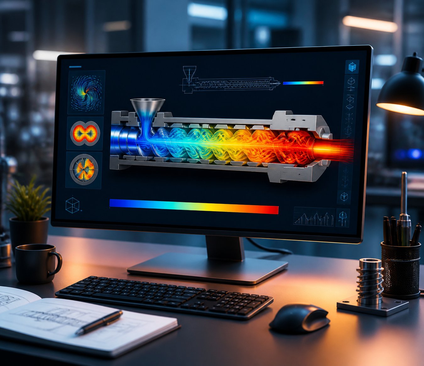
A skilled engineer can look at a screw profile and predict — roughly — how it will perform. But "roughly" is not good enough when you are developing a glass-fiber-reinforced compound that must hit a specific fiber-length distribution, or a pharmaceutical amorphous solid dispersion where a five-degree melt temperature overshoot degrades the active ingredient. The number of possible screw element combinations on a typical 40:1 extruder easily exceeds tens of thousands. Testing even a fraction of those on a physical machine burns weeks of trial time, kilograms of material, and significant budget. Computational design tools collapse that search space dramatically — letting engineers screen, refine, and validate screw configurations digitally before a single pellet enters the feed hopper.
Three tiers of simulation now serve this purpose, each operating at a different resolution and speed. Understanding when to deploy each one — and how they connect — is what separates modern, data-driven twin screw extruder design from the trial-and-error traditions it is replacing.
1D Process Simulation for Rapid Screw Profile Screening
Imagine being able to compare thirty different screw configurations in a single afternoon, each one evaluated for fill level, pressure, temperature, residence time, and specific mechanical energy along the entire barrel length. That is exactly what 1D process simulation delivers. These tools model the extruder as a chain of connected functional zones — each zone defined by its screw element geometry, barrel temperature, and material rheology — and solve the governing equations in the axial direction only, ignoring radial flow details to gain speed.
Several established software packages serve this role, including Ludovic, Akro-Co Twin-Screw, and Sigma. They share a common foundation: each screw element is characterized by a set of dimensionless parameters — typically pressure parameters (A1, A2) and power parameters (B1, B2) — that capture its conveying capacity, pressure buildup capability, and energy dissipation behavior as functions of throughput and screw speed. For shear-thinning materials, which describe most real polymer melts, additional parameters (A3, B3) account for how viscosity changes under different shear conditions within each element.
The practical value is enormous. Feed in your polymer's rheological data, define your screw profile element by element, set your barrel temperatures and throughput, and within seconds the software returns a complete axial profile showing:
- Fill level along the screw length — identifying where the screw runs starved versus fully filled, critical for verifying vent port locations.
- Pressure distribution — revealing whether melt seals form where intended and whether die pressure is sufficient.
- Temperature evolution — tracking how viscous dissipation and barrel heat transfer combine to determine actual melt temperature zone by zone.
- Residence time distribution — flagging zones where material dwells too long and risks thermal degradation.
- Specific mechanical energy (SME) — quantifying total energy input per kilogram, a key predictor of mixing intensity and product quality.
Researchers at MINES ParisTech confirmed that 1D models like Ludovic provide very satisfactory results for flows in screw conveying elements, accurately predicting maximum pressure, filled length, and SME across a range of screw speeds and feed rates. For simple configurations — forward conveying elements and straightforward kneading zones — the 1D approach matches 3D simulation results closely while running in a fraction of the time.
Where does the 1D approach fall short? It struggles with the finer geometric details of kneading blocks. The same MINES ParisTech study found that 1D models treat all positive stagger angles as producing the same maximum pressure, because the simplified flow equations cannot distinguish how different stagger geometries create pseudo-flight effects at the disc tips. Similarly, 1D models show SME as independent of stagger angle and disc thickness — a limitation that matters when you are fine-tuning a demanding dispersion zone. For conveying-dominated profiles or early-stage screening, 1D simulation is fast and reliable. For optimizing the precise geometry of mixing-intensive zones, you need higher-resolution tools.
CFD and DEM for Detailed Flow and Particle Analysis
When the question shifts from "does this profile work overall?" to "what exactly happens inside this specific kneading block?", three-dimensional computational fluid dynamics (CFD) takes over. CFD simulation for twin screw extruder design resolves the actual velocity fields, shear rate distributions, pressure gradients, and temperature maps within individual element geometries — revealing flow details that 1D models cannot access.
Modern 3D approaches use several numerical strategies. The finite element method, employed by tools like XimeX, solves the governing Navier-Stokes equations on meshes that adapt to the complex, time-varying geometry of rotating screws within the barrel. A technique called the domain immersion or fictitious domain method simplifies this challenge by embedding the screw geometry into a larger computational domain using level-set functions — avoiding the need to re-mesh the entire domain every time the screws rotate. The result is a detailed 3D flow field that engineers can interrogate at any point in the channel.
What can CFD reveal that simpler methods cannot? Consider three high-value applications:
- Stagger angle and disc thickness effects: The MINES ParisTech comparison showed that 3D simulation detects how SME varies with stagger angle — decreasing as the angle increases — and how disc thickness influences maximum pressure, with thinner discs producing higher pressures for reverse stagger configurations. These nuances are invisible to 1D models but critical for optimizing dispersion zones.
- Dead zones and hot spots: CFD can map regions of stagnant flow where material accumulates and degrades, as well as localized temperature peaks caused by intense viscous dissipation. Identifying these "hot spots" before building the screw prevents degradation-related quality defects that are expensive to diagnose experimentally.
- Mixing quantification through particle tracking: By releasing virtual tracer particles into the simulated flow field and following their trajectories, engineers can calculate mixing indices, residence time distributions, and the intensity of segregation. This provides a direct, quantitative comparison of mixing performance between candidate screw configurations.
The trade-off, of course, is computational cost. A single 3D flow computation for a 50 mm kneading block section — covering one half-turn of the screws at 100 time steps — can require approximately 200 hours on 34 processors, as the MINES ParisTech team reported. That makes full-extruder 3D simulation impractical. Instead, CFD is used surgically — zooming into the two or three critical zones identified by 1D screening, such as the primary dispersion section or a problematic vent region.
Discrete Element Method (DEM) simulation fills yet another gap, one that neither 1D nor CFD addresses well: the behavior of solid particles before they melt. DEM simulation for solids conveying in twin screw systems models individual pellets, powder granules, or filler particles as discrete objects that interact through contact forces, friction, and gravity. This is particularly valuable in the feed zone and early conveying sections, where bulk solids behavior — bridging, segregation, compaction — often determines whether the extruder can achieve its target throughput. A joint research project between SKZ and TU Dortmund is advancing the state of the art further, developing simulation tools that model the melting transition itself — the point where solid granules transform into a continuous polymer melt — by combining 3D melting models originally developed for single-screw extruders with twin-screw flow frameworks.
Bridging Simulation and Physical Prototyping
No simulation replaces the physical extruder. Material behavior is too complex, process interactions too nonlinear, and real-world variability too unpredictable for any model to serve as the final word. What computational tools do — and do exceptionally well — is eliminate the majority of dead-end configurations before you ever run the machine. Instead of testing twenty screw profiles on the production floor, you test three. Instead of spending a week on trial runs, you spend a day confirming what the simulations predicted.
The most effective engineering teams follow a structured, three-stage workflow that moves from broad screening to focused refinement to physical validation:
- 1D screening: Use 1D process simulation to evaluate dozens of candidate screw profiles rapidly. Compare fill levels, pressure profiles, temperature evolution, and SME across configurations. Eliminate any profile that fails to meet basic process requirements — insufficient die pressure, excessive melt temperature, improper vent zone fill levels. Narrow the field to three to five promising candidates in hours rather than weeks.
- 3D CFD refinement of critical zones: For the surviving candidates, apply CFD to the most demanding sections — typically the primary mixing zone, the dispersion kneading block, or a problematic devolatilization region. Evaluate shear rate distributions, identify dead zones, compare mixing indices through particle tracking, and verify that disc thickness and stagger angle choices deliver the intended flow patterns. This step replaces the intuition-driven "try it and see" approach with quantitative evidence.
- Physical validation on the extruder: Run the top one or two configurations on the actual machine. Measure melt temperature, torque, throughput, and product quality against the simulation predictions. Use any discrepancies to calibrate the model for future iterations — improving its accuracy for the next project rather than starting from scratch every time.
This simulation-to-validation workflow does not just save time and material. It builds institutional knowledge. Every validated simulation run adds data points that sharpen the model's predictive power, making each subsequent project faster and more accurate. Teams that invest in this capability compound their advantage over time — running fewer trials, hitting targets sooner, and scaling new formulations with greater confidence.
Simulation tells you how flow, stress, and temperature behave inside the barrel for any given configuration. What it cannot tell you — at least not without context — is which configuration matters most for your specific application. Polymer compounding, pharmaceutical hot-melt extrusion, food processing, and reactive extrusion each impose fundamentally different priorities on screw profile design, and those priorities reshape which elements, which L/D ratios, and which mixing strategies deliver the best results.
Application-Specific Twin Screw Extruder Screw Profile Design Across Industries
A screw profile that produces flawless glass-fiber-reinforced nylon can destroy a pharmaceutical amorphous solid dispersion in minutes. The elements are the same — conveying segments, kneading blocks, reverse flights — but the priorities governing their selection, arrangement, and aggressiveness shift so dramatically between applications that a profile optimized for one industry may be fundamentally wrong for another. Understanding these application-driven priorities is what separates a versatile design engineer from one who only knows a single process.
Polymer Compounding and Masterbatch Production
Twin screw extruder screw design for polymer compounding is defined by one relentless demand: move high volumes of material through aggressive mixing zones without destroying the polymer or the reinforcement. Compounding glass-fiber-reinforced engineering plastics, mineral-filled polyolefins, or flame-retardant concentrates typically requires multiple kneading sections capable of high dispersive stress — wide discs at 60° to 90° stagger — to break apart filler agglomerates and force wetting at the polymer-filler interface. Side feeding downstream of the primary melting zone is nearly universal for abrasive fillers, protecting the feed zone from unnecessary wear and allowing the polymer to fully melt before encountering hard particles.
These requirements push compounding lines toward longer L/D ratios — commonly 40:1 to 48:1 — to accommodate the sequence of melt, disperse, side feed, redistribute, devolatilize, and meter. Screw speeds run high (300 to 600 RPM on commercial machines) to maximize throughput, and barrel liners shift to bimetallic or tungsten carbide grades to withstand abrasive wear.
Masterbatch production twin screw extruder design, by contrast, pivots the mixing priority. Color masterbatch demands exceptionally uniform pigment distribution throughout the carrier resin — a distributive mixing challenge more than a dispersive one, assuming pigments arrive pre-dispersed or are adequately broken down in the initial kneading zone. Profiles for color concentrates lean heavily on toothed mixing elements (ZME/TME) and narrow kneading discs at forward stagger angles to multiply the number of flow-splitting and recombining events per unit length. The goal is spatial homogeneity, not brute-force shear. Over-shearing a pigment that has already been dispersed wastes energy and raises melt temperature unnecessarily.
Pharmaceutical Hot-Melt Extrusion and Food Processing
Screw profile design for pharmaceutical hot melt extrusion operates under constraints that would seem extreme to a plastics compounder. Active pharmaceutical ingredients (APIs) are often thermally sensitive compounds where a 10°C overshoot can trigger degradation and compromise drug stability. As pharmaceutical HME research confirms, the barrel temperature must remain above the polymer's glass transition temperature yet below the degradation threshold of both carrier and API — a window that can be as narrow as 20 to 30 degrees Celsius for compounds like nimodipine in Kollidon VA64.
This thermal sensitivity reshapes every profile decision. Kneading zones are kept short — often a single section positioned two-thirds of the way down the barrel — to minimize residence time at elevated temperature. Stagger angles rarely exceed 60°, because the zero-conveying dwell time of 90° blocks creates unacceptable degradation risk. Screw speeds are calibrated carefully: too slow extends residence time and promotes thermal breakdown, too fast generates excessive viscous dissipation. Twin screw extruders are preferred over single screw machines in pharma HME specifically because their superior mixing efficiency achieves molecular-level dispersion — converting crystalline APIs into amorphous solid dispersions — with shorter barrel lengths and tighter residence time distributions.
Food extrusion introduces an entirely different variable set. Moisture acts as both a plasticizer and a reactant, driving starch gelatinization and protein texturization. Screw profiles must manage water injection points, steam generation within the barrel, and the dramatic viscosity changes that occur as starch transitions from granular to gelatinized states. Kneading blocks serve a dual purpose here — mechanical mixing and thermomechanical cooking — and the degree of fill in these sections directly influences the texture and expansion of the final product. Die design becomes inseparable from the screw profile, because the pressure drop across the die controls puffing and cell structure formation in expanded snacks and cereals.
Reactive Extrusion and Specialty Applications
Reactive extrusion twin screw screw configuration demands something no other application does: precise residence time control matched to reaction kinetics. Whether the process involves grafting maleic anhydride onto polyolefin backbones, chain-extending recycled PET, or crosslinking silane-functionalized polyethylene, the screw must provide enough mixing and dwell time for the reaction to reach target conversion — but not so much that side reactions, degradation, or gelation occur.
This creates profiles with multiple injection points for initiators, catalysts, or monomers, each positioned where the melt is at the correct temperature and viscosity for that reagent. Devolatilization stages — often two or more vacuum vents — remove reaction byproducts and unreacted monomers. Coperion's devolatilization data illustrates the range: from removing 3,000 ppm ethylene from LDPE down to below 1,000 ppm, to stripping 50% acetone from acrylic adhesive solutions to under 1,000 ppm. Each vent requires a proper melt seal upstream, large-pitch conveying beneath the vent opening, and sufficient vacuum capacity — all of which consume barrel length and push L/D ratios toward 48:1 or 52:1.
The table below captures how these application-driven priorities translate into concrete design choices:
| Application | Primary Mixing Priority | Typical L/D Range | Critical Design Considerations |
|---|---|---|---|
| Polymer compounding (filled/reinforced) | Dispersive — filler deagglomeration and wetting | 40:1 – 48:1 | Side feeding, abrasion-resistant liners, multiple kneading zones, high screw speed |
| Color masterbatch | Distributive — uniform pigment spatial distribution | 32:1 – 40:1 | Toothed mixing elements, narrow kneading discs, minimal over-shearing |
| Pharmaceutical HME | Molecular-level dispersion with minimal thermal load | 24:1 – 40:1 | Narrow thermal window, short kneading zones, tight RTD control, API stability |
| Food extrusion | Thermomechanical cooking and texturization | 20:1 – 32:1 | Moisture management, steam handling, die-dependent expansion, variable viscosity |
| Reactive extrusion | Residence time matched to reaction kinetics | 48:1 – 52:1 | Multiple injection points, multi-stage devolatilization, precise melt seal positioning |
What becomes clear from this comparison is that no universal screw profile exists. Each application imposes its own hierarchy of constraints — thermal, mechanical, chemical, and throughput-related — that must be resolved through targeted element selection, sequencing, and barrel configuration. Engineers working across these diverse domains often find that application-specific screw profile design benefits from expert consultation, particularly when navigating unfamiliar polymer-filler-process interactions for the first time. Services like NANHAIYA's Custom Screw Design provide screw geometry, material selection, and processing recommendations tailored to specific machine conditions and formulations — a practical resource for teams scaling into new applications without years of in-house trial history.
Even with the right application-specific profile in place, however, real-world extrusion rarely runs perfectly from day one. Surging output, inconsistent mixing, excessive melt temperatures, and devolatilization failures are the everyday realities that drive engineers back to the screw profile — asking not "what should I design?" but "what went wrong, and which element do I change to fix it?"
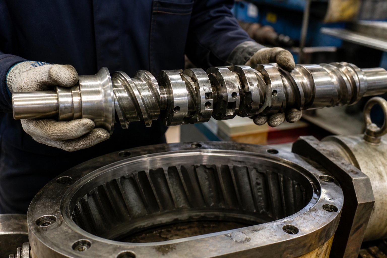
Troubleshooting Common Design-Related Twin Screw Extrusion Problems
Your barrel temperatures look right. Your feeders are calibrated. Your resin is properly dried. Yet the extruder still surges, the melt runs too hot, or the vent floods every third run. When obvious process variables check out fine, the root cause almost always traces back to the screw profile itself — an element placed in the wrong position, a kneading section that is too aggressive for the formulation, or a melt seal that is too weak to hold under real operating conditions. Twin screw extruder troubleshooting through screw design is the diagnostic skill most engineers need but few resources teach, because it requires connecting visible symptoms at the die to invisible flow behavior inside the barrel.
The sections below map the most common extrusion failures directly to their screw profile causes — and, more importantly, to the specific element modifications that resolve them.
Diagnosing Surging, Poor Mixing, and Excessive Melt Temperature
Output surging — the rhythmic pulsing of melt pressure and strand diameter at the die — frustrates operators because it mimics feeding problems even when feeders are running perfectly. So how do you fix surging in twin screw extrusion when the feed system is not the culprit? Look at the metering zone. Surging often originates from inconsistent fill in the final conveying section before the die. If the restrictive elements upstream — kneading blocks or reverse flights — create an overly aggressive melt seal, material accumulates and then releases in slugs rather than flowing continuously. The fix involves reducing the intensity of the restriction: swap a reverse kneading block for a neutral one, shorten a reverse-flight element by one L/D, or reposition the melt seal slightly upstream to give the metering zone more conveying length to stabilize flow. As Kerke's troubleshooting data confirms, fluctuating melt pressure at the die head frequently traces back to pressure imbalances inside the screw rather than to feeding inconsistency.
Poor mixing shows up as streaks in color concentrates, undispersed filler agglomerates visible under magnification, or inconsistent mechanical properties across a production run. The diagnostic question is not "do I need more mixing?" but "do I need more dispersive mixing, more distributive mixing, or both?" Streaks in a masterbatch where the pigment particles are already fine enough point to a distributive deficit — the particles are small but not evenly spread. Adding toothed mixing elements (ZME) or replacing wide kneading discs with narrow ones at forward stagger angles addresses this directly. Visible agglomerates, by contrast, indicate a dispersive shortfall — the particles were never broken down in the first place. Here, the solution runs opposite: widen the kneading discs, increase the stagger angle toward 90 degrees, or add a reverse element downstream of the kneading section to force more material through the high-shear overflight gap.
Excessive melt temperature is the most common twin screw extruder complaint that engineers misdiagnose as a barrel heating problem. The excessive melt temperature twin screw extruder causes are almost always mechanical, not thermal. Aggressive kneading blocks — particularly wide discs at 90-degree stagger angles stacked in long sequences — convert so much mechanical energy into heat that barrel cooling cannot extract it fast enough. Leistritz's boundary condition analysis reinforces this point: elevated melt temperature results from screw RPMs, mixing element aggressiveness, and OD/ID ratio effects that collectively push viscous dissipation beyond what barrel cooling can manage. The screw profile fix is targeted de-intensification — replace wide 90-degree kneading discs with narrow 60-degree ones, substitute distributive toothed elements for some kneading blocks, or extend the conveying sections between mixing zones to give the melt more time to shed heat to the barrel wall.
Solving Devolatilization Failures and Torque Overload
When vacuum vents flood with polymer or residual volatiles persist in the finished product despite adequate vacuum levels, the problem is rarely the vacuum pump. A devolatilization failure twin screw screw profile fix starts with the melt seal. Every vacuum vent requires a fully filled, pressure-tight melt seal immediately upstream — typically formed by a reverse-flight element, a reverse kneading block, or a blister ring. If that seal is too short, too far from the vent opening, or uses an element that does not generate enough back-pressure for the current throughput, downstream pressure from the die or screen pack pushes the filled-screw backup length past the vent opening, flooding it with melt.
Even with a proper seal, devolatilization efficiency depends on the free surface area of melt exposed under the vent. The screw section beneath the vent must use large-pitch conveying elements that keep fill levels low — ideally below 30 percent — so thin melt films form on the screw surface and barrel wall, giving volatiles a short diffusion path to the vapor space. If fill is too high, volatiles remain trapped inside the bulk melt regardless of vacuum intensity. Leistritz's devolatilization guidelines emphasize that increasing screw RPM or decreasing feed rate generally improves DV efficiencies by creating smaller melt pools and more renewed surface area — but warn that degradation may follow if other boundary conditions are exceeded.
Torque overload — signaled by high motor amperage, frequent drive trips, or inability to reach target screw speed — points to excessive restriction in the screw profile relative to throughput. Too many reverse elements, too many aggressive kneading blocks stacked in series, or a die with insufficient open area all force the motor to work harder than its rating allows. The diagnostic approach is systematic: temporarily reduce feed rate while maintaining screw speed. If torque drops proportionally, the profile restriction is the bottleneck. The fix involves removing one reverse element, shortening a kneading section, or replacing a 90-degree kneading block with a 60-degree one — each change reducing the pressure the motor must overcome. Leistritz notes that for torque-limited processes, removing several kneading elements and increasing zone temperature setpoints in the melting zone can facilitate higher throughput within the same torque envelope.
When to Seek Expert Screw Design Support
Not every problem has a single-element fix. The most stubborn extrusion issues involve multiple interacting variables — a polymer that is both shear-sensitive and difficult to disperse, a filler that is abrasive and low in bulk density, or a reactive process where residence time, temperature, and mixing intensity must all hit narrow windows simultaneously. For these scenarios, use the quick-reference diagnostic guide below as a starting point:
- Output surging at die: Reduce melt seal intensity, lengthen metering conveying section, verify consistent fill upstream of restriction.
- Undispersed agglomerates: Increase kneading disc width, raise stagger angle toward 90 degrees, add reverse element after kneading section.
- Streaks or uneven additive distribution: Add toothed mixing elements (ZME/TME), replace wide kneading discs with narrow forward-stagger discs.
- Melt temperature exceeds target by more than 20 degrees Celsius: Replace wide 90-degree kneading blocks with narrow 60-degree discs, reduce total kneading section length, increase conveying length between mixing zones.
- Vent flooding: Strengthen melt seal upstream of vent (longer reverse element or blister ring), reduce fill under vent by increasing conveying pitch.
- Insufficient volatile removal: Verify melt seal integrity, increase screw RPM to reduce fill and renew surface area, add a second vent stage if barrel length permits.
- Torque overload at target throughput: Remove one restrictive element, shorten kneading sections, check die for excessive back-pressure, raise melting zone temperatures to reduce viscosity.
- Fiber breakage in reinforced compounds: Relocate fiber side-feeding downstream of all high-shear kneading zones, replace kneading blocks after the side feeder with low-shear distributive elements.
Screw profile optimization is iterative and data-driven — each adjustment changes the pressure, fill, shear, and temperature landscape simultaneously, so systematic single-variable changes with measured outcomes outperform intuitive multi-element swaps every time.
When the diagnostic guide above resolves your issue in one or two iterations, the problem was straightforward. When it does not — when fixing the melt temperature creates a mixing deficit, or strengthening the melt seal triggers torque overload, or the formulation demands conditions that seem mutually exclusive — the system has moved beyond single-variable troubleshooting into multi-variable optimization. These are the scenarios where polymer rheology, element geometry, barrel thermal response, and die restriction interact in ways that exceed intuitive reasoning.
For production teams and machine rebuilders facing persistent, design-related processing problems that resist simple fixes, specialized engineering support can short-circuit weeks of trial-and-error. NANHAIYA's Custom Screw Design Services provide screw geometry, material pairing, and processing recommendations tailored to specific polymers, machine platforms, and output targets — a practical next step when the problem demands coordinated changes across multiple subsystems rather than isolated element swaps.
Twin Screw Extruder Design FAQs
1. What is the most important factor in twin screw extruder design?
The most important factor is co-optimization of every subsystem — screw elements, barrel thermal zones, drive capacity, feeding strategy, and die geometry — as a single integrated system. Isolated decisions, such as selecting aggressive kneading blocks without accounting for barrel cooling capacity, lead to problems like excessive melt temperature or polymer degradation. Engineers should map the full pressure and shear profile from feed throat to die exit before finalizing any single component choice. For complex formulations, services like NANHAIYA's Custom Screw Design (https://www.nhyscrews.com/services/custom-screw-design) help teams coordinate these interdependent variables based on specific polymers and machine platforms.
2. How do I choose the right L/D ratio for my twin screw extruder?
Start by listing every functional zone your process requires — melting, mixing, side feeding, devolatilization, metering — then select the shortest L/D ratio that accommodates all of them. Simple blending tasks typically fit within 32:1, while glass-fiber-reinforced compounding usually needs 40:1 for side feeding and venting. Reactive extrusion or multi-stage devolatilization may demand 48:1 to 52:1. Avoid choosing longer barrels than necessary, because additional length increases residence time, energy consumption, and the risk of thermal degradation for heat-sensitive materials.
3. What is the difference between dispersive and distributive mixing in twin screw extrusion?
Dispersive mixing breaks apart agglomerates, droplets, or phase domains by applying shear stress that exceeds cohesive or interfacial forces — achieved with wide kneading discs at 60 to 90 degree stagger angles and tight screw-to-barrel clearances. Distributive mixing spatially redistributes already-dispersed particles uniformly throughout the matrix by splitting and recombining flow streams — achieved with toothed mixing elements (ZME/TME) and narrow kneading discs at 30 to 45 degree forward stagger. Most real formulations need both types sequentially: dispersive elements first to break down particles, then distributive elements to spread them evenly.
4. Why does my twin screw extruder produce excessive melt temperature despite correct barrel setpoints?
Excessive melt temperature is almost always caused by viscous dissipation from overly aggressive screw elements rather than barrel heating errors. Wide kneading discs at 90 degree stagger, long kneading sections stacked without intervening conveying segments, and high screw speeds all convert mechanical energy into heat faster than barrel cooling can extract it. The fix involves targeted de-intensification: replace wide 90 degree kneading blocks with narrow 60 degree ones, substitute distributive toothed elements for some kneading blocks, or extend conveying sections between mixing zones to allow the melt more time to transfer heat to the barrel wall.
5. How do screw element stagger angles affect twin screw extruder performance?
Stagger angle controls both the mixing intensity and the forward conveying action of kneading blocks. A 30 degree stagger retains strong forward conveyance with moderate mixing, making it suitable for gentle initial melting of heat-sensitive polymers. A 60 degree stagger balances conveying and shear for general-purpose compounding. A 90 degree stagger eliminates net forward conveying entirely, maximizing local residence time and shear stress for aggressive dispersion tasks like pigment deagglomeration. Reverse stagger angles push material backward, creating melt seals essential for devolatilization. Each angle simultaneously affects fill level, energy input, and pressure along the screw.
Written by
Nanhaiya Technical Team
Zhoushan Nanhaiya Plastic Machinery Co., Ltd.
The Nanhaiya technical team supports screw and barrel manufacturing projects through application review, technical communication, custom manufacturing coordination, and production and quality control.
Discuss Your Application
Related Articles
More insights on screw barrel technology and plastics processing.

What Nobody Tells You About Screw Barrel For Plastic Machine Design
Oct 10, 2026
Learn how screw barrel for plastic machine design affects melt quality, throughput, and wear life. Covers geometry, resin matching, troubleshooting, and sourcing.
Read Article
Single Screw Extruder for Sheet: Stop Guessing, Start Specifying
Oct 9, 2026
Learn how to specify a single screw extruder for sheet production. Covers screw geometry, resin-specific processing, troubleshooting, and maintenance best practices.
Read Article
PE Pipe Extruder Machine: What Datasheets Won't Tell You
Oct 9, 2026
Learn how a PE pipe extruder machine works, key specs explained, material grade selection, maintenance tips, and buyer guidance beyond the datasheet.
Read ArticleLooking for something else?
Search by material, symptom or product and jump straight to the relevant page.
These are navigation suggestions based on keyword matching — not a quotation, not a delivery commitment, and not a substitute for engineering review. Final specification is confirmed by our engineers against your drawings and processed material.
Need help with screw barrel selection?
Share your machine model, processed material and application. Our team can help with pricing and technical support.