

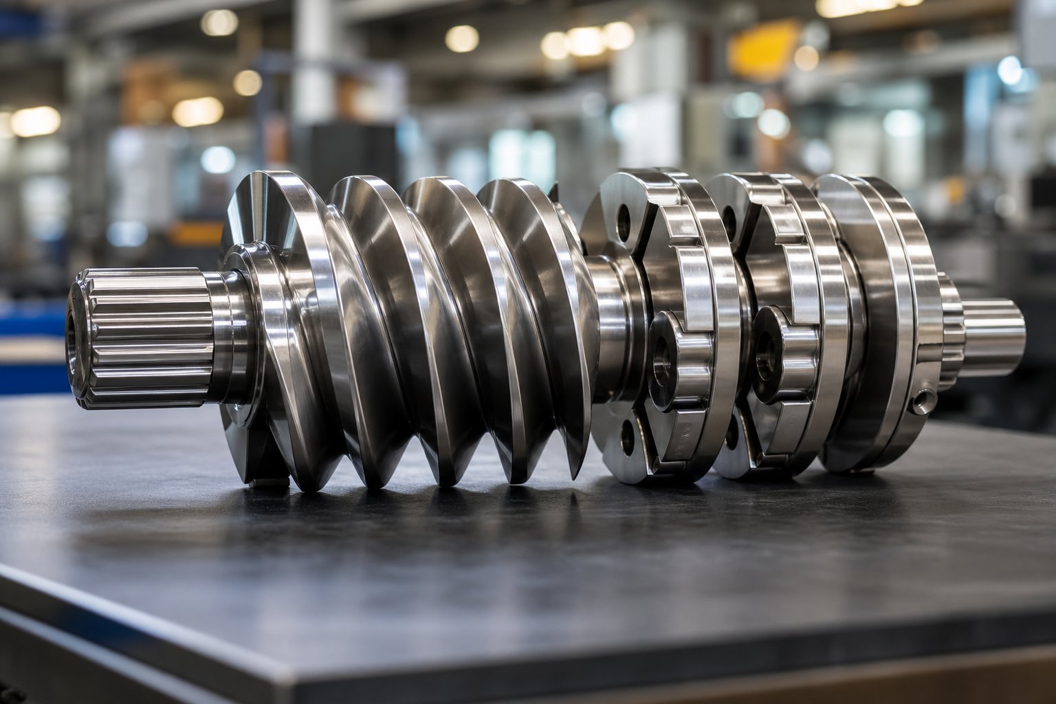
What Screw Elements Are and Why They Matter
Imagine you could rearrange the internal geometry of your extruder the way you swap tools on a workbench - picking the right one for each job. That is exactly what screw elements allow you to do inside a twin-screw extruder. But what are they, and why do they carry so much influence over product quality?
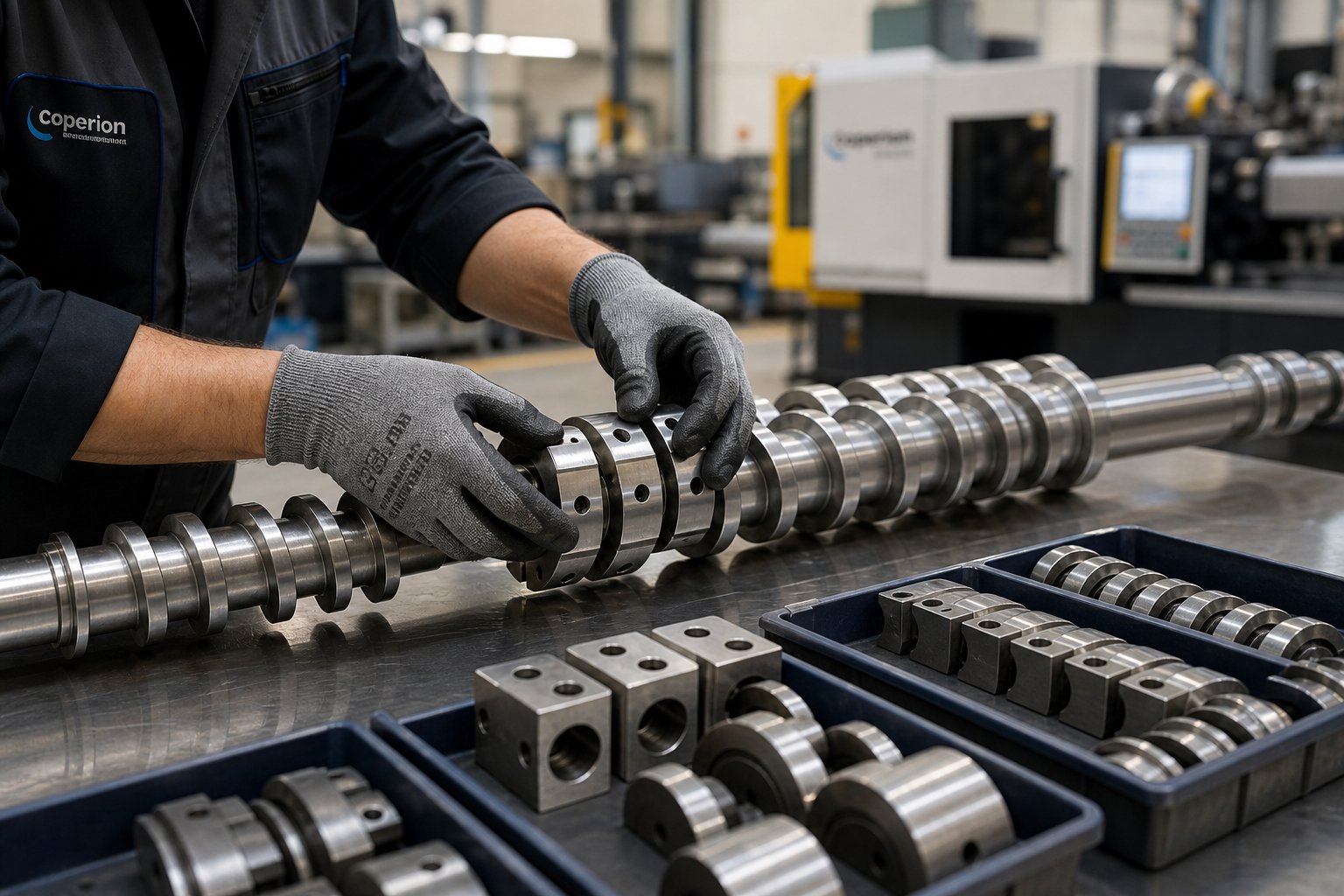
Screw elements are modular, interchangeable components that slide onto a splined shaft to form the complete screw profile inside an extruder barrel. Each element features a specific geometry - defined by its pitch, flight depth, disc angle, or tooth pattern - that produces a targeted processing effect such as conveying, melting, mixing, devolatilizing, or pressurizing the material.
In short, the extruder screw is the engine of the extrusion process, and screw elements are its individually tunable cylinders. Change one element, and you change how material flows, how much shear it receives, and how long it stays inside the barrel. That level of control is why engineers treat element selection as the primary lever for process optimization.
Defining Screw Elements in Polymer Extrusion
Every element in a screw profile serves a purpose tied directly to its shape. A deep-flighted conveying element moves bulk material forward quickly with minimal energy input. A stack of elliptical kneading discs - based on the Erdmenger self-wiping profile concept - applies intense shear to melt and mix. A toothed mixing element redistributes ingredients without aggressive particle breakdown. The principle is straightforward: geometry dictates function. By arranging different geometries in sequence along the shaft, engineers build a screw profile that guides the material through a deliberate series of processing stages - from raw feed intake all the way to stable die discharge.
This is what makes screw extrusion so versatile. The same extruder barrel can process rigid PVC compounds one week and glass-fiber-reinforced nylon the next, simply by rearranging the elements on the shaft.
Single-Screw vs. Modular Twin-Screw Element Systems
Here is a distinction that often trips up newcomers: not every extruder screw is modular. If you work with a single-screw extruder, the screw is typically manufactured as one monolithic piece. Its flight geometry - root depth, pitch transitions, mixing sections - is machined directly into a solid shaft. You can optimize the design before manufacturing, but once the screw is built, you cannot reconfigure it on the fly. Changing the processing profile means ordering an entirely new screw.
Twin-screw extruders, particularly co-rotating intermeshing designs, take a fundamentally different approach. Individual elements - conveying segments, kneading blocks, toothed mixers, reverse-flight restrictors - slide onto a splined shaft and are held in place by a locking mechanism. This modular architecture means you can pull the screws, swap a few elements, and completely change the shear profile, residence time, or pressure characteristics of the machine. Need gentler melting for a heat-sensitive polymer? Replace aggressive kneading blocks with narrower-angle discs. Need stronger back-pressure for vacuum venting? Drop in a reverse element or blister ring.
This modularity is exactly why twin-screw platforms dominate applications that demand frequent recipe changes - compounding, masterbatch, reactive extrusion, and recycling. It also means that understanding what each element does, and where it belongs, is not optional knowledge. It is the difference between a well-tuned process and one plagued by surging, degradation, or poor dispersion.
The sections ahead break this down systematically - element by element - covering geometry, function, zone placement, stagger angle logic, wear considerations, and real-world troubleshooting so you can make confident, informed decisions about your screw profile.
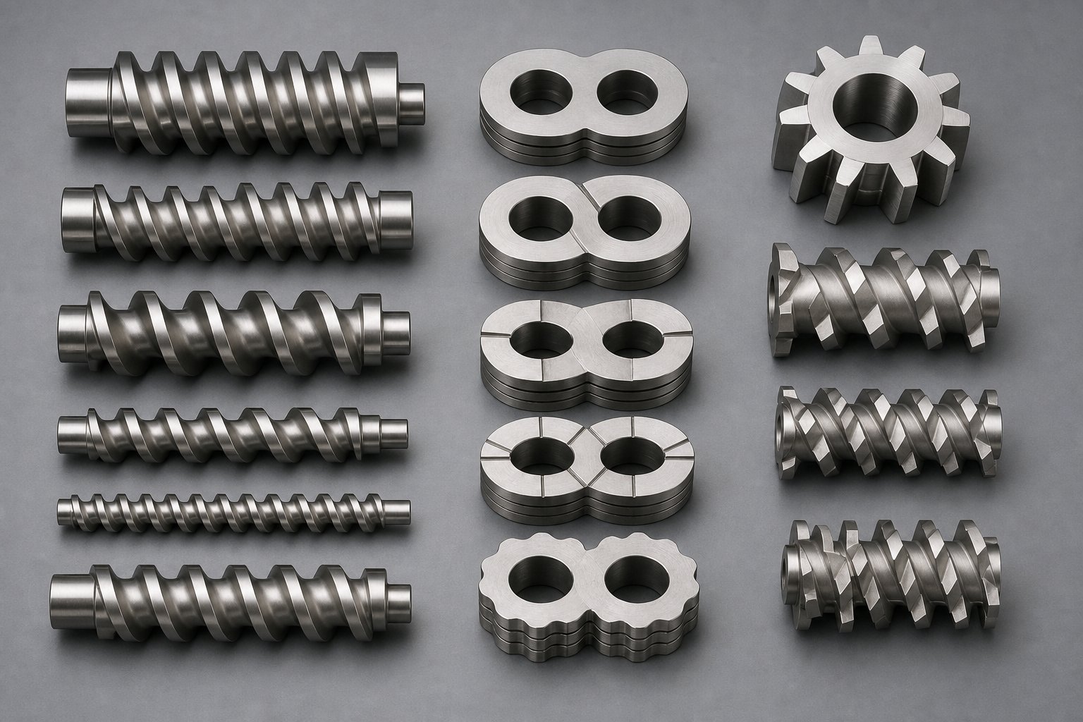
Complete Taxonomy of Screw Element Types
Every extrusion screw profile is built from a surprisingly small family of element categories. Yet within each category, subtle geometry changes - a shift in pitch, a different disc width, an added tooth row - produce dramatically different processing effects. Think of it like an alphabet: only a handful of letter shapes, but nearly infinite words you can spell. Below is a definitive breakdown of every major type you will encounter.
Conveying Elements and Their Flight Geometry
Conveying elements are the workhorses of any screw design. They feature helical flights wrapped around a cylindrical core, and their primary job is to transport material through the barrel. You will sometimes hear them called "transport elements" or simply "screw segments." Their geometry follows the Erdmenger self-wiping profile, ensuring the intermeshing twin screws continuously wipe each other's surfaces and prevent stagnation.
The defining parameter here is pitch - the axial distance the flight travels in one full revolution. Pitch is often expressed as a multiple of the screw diameter (D):
- Large pitch (1.5D to 2D): Moves a high volume of material quickly, keeps fill level low, and minimizes residence time. Ideal for the feed zone or wherever you need to pull material forward rapidly - especially useful for heat-sensitive polymers that degrade with prolonged thermal exposure.
- Medium pitch (around 1D): Balances conveying capacity with moderate fill, making it the go-to choice for transitional sections between processing zones.
- Small pitch (approximately 0.4D to 0.5D): Restricts forward flow, increases barrel fill, and builds pressure. Processors rely on tight-pitch elements in the metering zone to deliver stable die pressure and improve melt homogeneity.
Reverse-flight conveying elements - sometimes labeled with an "L" suffix to indicate left-handed rotation - deserve special attention. Instead of pushing material forward, they actively oppose the flow direction. The result is localized back-pressure that creates a melt seal. You will typically find reverse-flight elements positioned upstream of vent ports or sandwiched between kneading block sections to intensify fill and shear in a targeted zone.
Kneading Blocks and Disc-Based Elements
If conveying elements are the legs of your screw profile, kneading blocks are its hands - they do the heavy work of melting, shearing, and blending. A kneading block consists of a stack of elliptical discs mounted on the shaft at offset angles relative to one another. That offset angle, called the stagger angle, is the single most influential parameter controlling how aggressively the block mixes.
Industry nomenclature follows a consistent pattern. A designation like KB45/5/30 tells you three things at a glance: a 45-degree stagger angle between successive discs, five discs in the stack, and a total element length of 30 mm. Some OEMs distinguish between half-disc kneading blocks (often labeled KP) and full-disc-width versions (KBW), with wider discs promoting stronger dispersive shear and narrower discs favoring distributive mixing.
Kneading blocks come in three conveying orientations:
- Forward-staggered (right-handed): Provides moderate mixing while still conveying material downstream. Less aggressive, suitable for initial melting stages.
- Neutral (90-degree stagger): Zero net forward conveying. Material dwells in the block longer, maximizing shear input - a powerful tool for breaking up agglomerates.
- Reverse-staggered (left-handed): Actively pushes material backward, creating the highest restriction, longest local residence time, and most intense mixing. Often used to form a melt seal ahead of vacuum vent zones.
Specialty Mixing and Sealing Elements
Beyond standard conveying and kneading geometries, several specialty elements fill niche but critical roles in a screw blade configuration.
Toothed mixing elements (ZME, TME, SME) use rows of interlocking teeth rather than continuous flights or discs. They excel at distributive mixing - splitting and recombining melt streams repeatedly - without imparting heavy shear. TME elements were among the earliest tooth-type designs and offer excellent lateral mixing, though they lack self-wiping capability. ZME elements improved on this by adding a slight reverse-conveying action and self-cleaning geometry. SME elements take yet another approach: they are essentially conveying elements with machined grooves that allow controlled leakage flow, combining forward transport with axial distribution.
Blister rings and restrictive elements serve as flow restrictors. A blister ring is a short, cylindrical disc with minimal clearance to the barrel wall. It creates a thin-film melt seal that separates pressure zones - essential for effective devolatilization, where you need a significant pressure drop at the vent opening to flash off volatiles.
| Element Type | Geometry | Primary Function | Typical Zone Placement |
|---|---|---|---|
| Large-pitch conveying | Deep helical flights, 1.5D-2D pitch | High-volume material transport, low fill | Feed zone, downstream of side feeders |
| Medium-pitch conveying | Standard helical flights, ~1D pitch | Balanced conveying and moderate fill | Transition sections between zones |
| Small-pitch conveying | Shallow helical flights, 0.4D-0.5D pitch | Pressure buildup, improved melt homogeneity | Metering / die discharge zone |
| Reverse-flight conveying | Left-handed helical flights | Back-pressure generation, melt sealing | Upstream of vent ports, between kneading sections |
| Forward kneading block | Staggered elliptical discs, right-handed offset | Moderate dispersive and distributive mixing | Melting zone, initial mixing zone |
| Neutral kneading block (90°) | Staggered elliptical discs, 90° offset | Maximum shear, zero net conveying | Intensive mixing / dispersion zone |
| Reverse kneading block | Staggered elliptical discs, left-handed offset | Maximum restriction, melt seal creation | Pre-vent seal zone, high-shear mixing zone |
| Toothed mixing (ZME/TME/SME) | Rows of interlocking teeth or grooved flights | Distributive mixing with low shear | Post-melting mixing zone, before compression |
| Blister ring / restrictive element | Short cylindrical disc, tight barrel clearance | Melt seal, pressure zone separation | Immediately upstream of vent or vacuum port |
With this taxonomy as a reference, the natural next question is not just what each element does, but how a single parameter - the kneading block stagger angle - can shift processing behavior from gentle melting to aggressive dispersion. That angular detail turns out to be one of the most powerful, and most misunderstood, levers in screw profile engineering.
Kneading Block Stagger Angles and Their Processing Effects
You have seen that kneading blocks come in forward, neutral, and reverse orientations. But what really separates a gentle melting profile from an aggressive dispersion setup often comes down to a single number: the stagger angle between successive discs. Change it by just 15 or 30 degrees and you will notice a measurable shift in melt temperature, mixing intensity, and throughput stability. So how does this angular offset actually control what happens to the polymer?
How Stagger Angle Controls Shear and Forwarding
Picture a kneading block screw element as a stack of elliptical paddles threaded onto the shaft. Each paddle is rotated by a fixed angle relative to the one before it. That rotation - the stagger angle - determines two things simultaneously: how much forward push the block gives the material and how aggressively it shears the melt.
The underlying principle is straightforward. When the stagger angle is narrow - say 30 degrees - each disc aligns closely with its neighbor. The result resembles a nearly continuous flight, so the block conveys material forward almost like a standard transport element. Polymer moves through quickly, residence time stays short, and shear input remains relatively low. As industry practitioners note, a 30-degree kneading block provides minimal mixing while conveying material forward optimally.
Widen the offset to 45 or 60 degrees and the picture changes. The growing gap between disc faces forces more polymer to flow over the disc tips rather than slipping smoothly from one paddle to the next. That tip region - the narrow clearance between the disc edge and the barrel wall - is where the shear rate peaks. A 60-degree kneading block, for instance, has noticeably poor forward-conveying capability but is far more efficient at mixing and energy input.
Push the angle all the way to 90 degrees and forward conveying drops to essentially zero. A neutral kneading block neither pushes material downstream nor upstream. Instead, the polymer dwells in the block, repeatedly passing over the disc tips and being sheared against the barrel wall. This makes 90-degree blocks powerful tools for dispersive mixing in a twin screw extruder - breaking down agglomerates, melting stubborn crystalline regions, and driving up melt temperature through mechanical energy input.
Reverse-staggered kneading blocks go a step further. By offsetting the discs in the opposite rotational direction (left-handed), the block actively pushes material backward. This creates a high-restriction zone that acts as a melt dam, dramatically increasing local fill and residence time. The result is the most intense mixing action available in a kneading block configuration - but also the highest risk of thermal degradation if overused.
| Stagger Angle | Forward Conveying Effect | Shear Intensity | Residence Time Impact | Best Used For |
|---|---|---|---|---|
| 30° (forward) | High | Low | Short | Gentle initial melting, transition from conveying to kneading sections |
| 45° (forward) | Moderate | Moderate | Moderate | General-purpose melting and moderate mixing |
| 60° (forward) | Low | High | Moderate to long | Intensive melting, dispersive mixing of pigments and fillers |
| 90° (neutral) | None | Very high | Long | Maximum shear dispersion, melt homogenization, melt dam restriction |
| Reverse (left-handed) | Negative (pushes backward) | Very high | Very long | Melt sealing before vent zones, high-intensity mixing of difficult compounds |
One additional variable interacts closely with stagger angle: disc width. Wider discs force more polymer over the tip clearance and act more like a plow, while narrower discs slice through the melt with less energy input. So a five-disc kneading block at 60 degrees with wide paddles will generate significantly more shear than a seven-disc block at the same angle with narrow paddles. Engineers consider both parameters together when fine-tuning how kneading blocks work in a given profile.
Practical Selection Logic for Kneading Block Configurations
Knowing what each angle does is one thing. Deciding which combination to use for a specific material and application - that is where screw profile design becomes, as experienced compounders often say, as much an art as a science.
Here are the guiding principles most processors follow:
- Shear-sensitive polymers (PVC, certain biopolymers, EVOH): Favor narrower stagger angles - 30 and 45 degrees - spread over a longer kneading block section. The material melts gradually with less peak shear, reducing the risk of degradation or discoloration.
- Crystalline polymers with high melting points (nylon, PET, PBT): Require sufficient energy input to fully melt the crystalline phase. A combination of 60-degree blocks followed by 90-degree neutral blocks ensures enough residence time and shear to eliminate unmelted particles.
- Aggressive pigment or filler dispersion: Calls for wider angles - 60 and 90 degrees - or even short reverse kneading sections. These configurations maximize the dispersive forces needed to break down tightly bonded agglomerates.
- Variable or contaminated feedstock (recycling applications): Benefits from a flexible approach, often combining kneading blocks with intermediate conveying elements to prevent excessive melt temperature buildup while still ensuring thorough melting.
One of the most effective strategies is the progressive shear ramp. Instead of jumping straight into high-shear elements, engineers arrange kneading blocks in ascending stagger angle order - for example, 30 degrees followed by 60 degrees followed by 90 degrees. This graduated sequence eases the feed material from conveying into increasingly intensive mixing. The 30-degree block pulls solid material into the melting zone and minimizes backflow. The 60-degree blocks then deliver stronger work input to initiate bulk melting. Finally, the 90-degree neutral blocks act as a restriction that ensures all polymer passing through the section is fully molten - functioning as a melt dam that increases fill level in that critical region of the screw.
Sounds simple in principle, but real-world formulations add complexity. Some processors find that a single continuous kneading block section produces excessively high melt temperatures or causes surging. In those cases, splitting the melting zone into two or three shorter kneading block groups separated by conveying elements can stabilize the process without sacrificing melt quality. Imagine it as giving the polymer brief recovery periods between bursts of intensive work.
The stagger angle sequence is the most influential design variable in a twin-screw melting section - more impactful than barrel temperature setpoints alone for controlling melt quality and energy input.
Choosing the right kneading block configuration is ultimately about matching shear intensity to the material's needs at each point along the barrel. Yet even a perfectly tuned stagger angle sequence will underperform if the elements are placed in the wrong processing zone - a topic that deserves its own systematic breakdown.
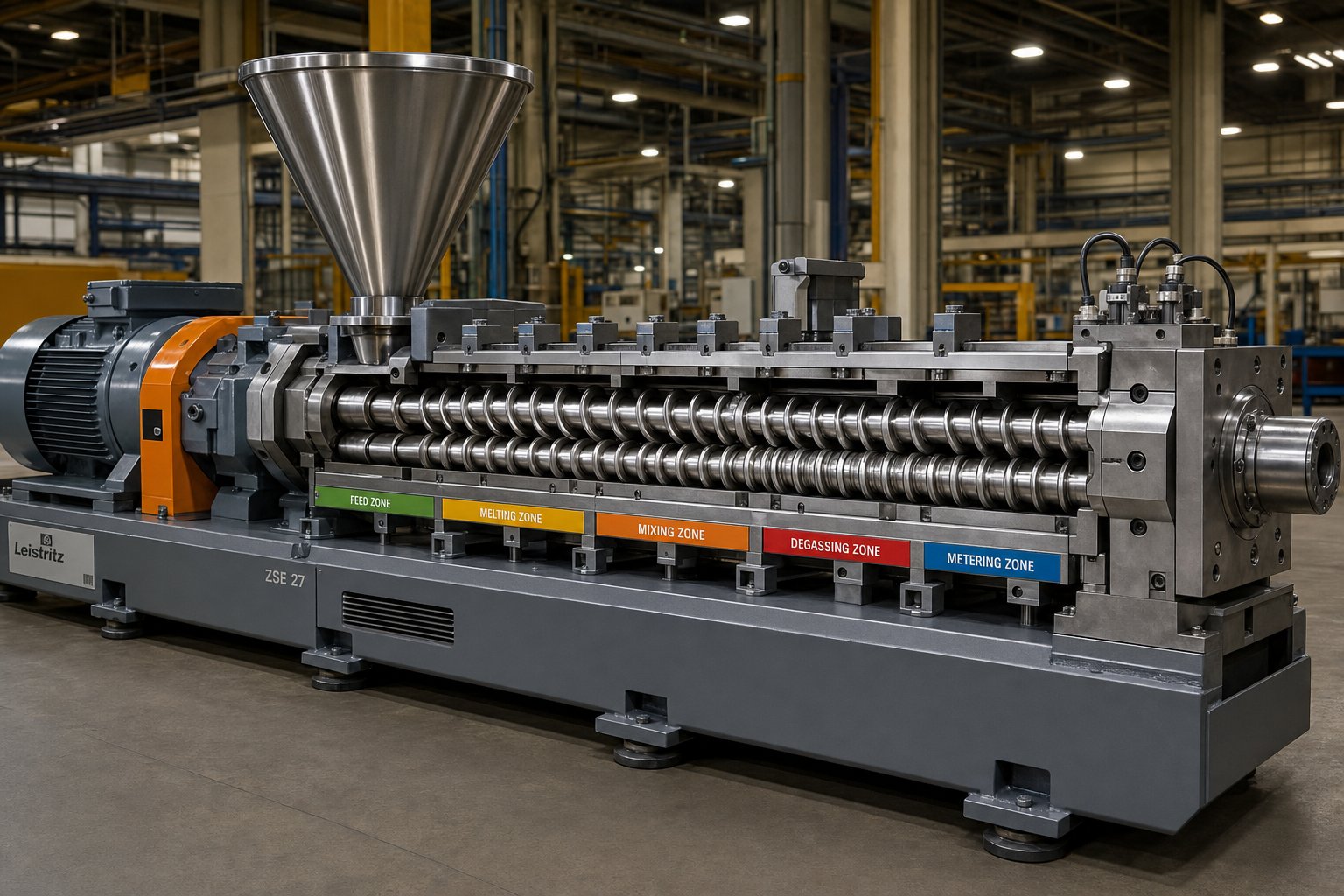
Mapping Screw Elements to Processing Zones
A kneading block with the perfect stagger angle, placed in the wrong location along the barrel, can wreck a process just as effectively as a poorly chosen element. Screw profile design for a twin screw extruder is not only about selecting the right components - it is about sequencing them so each zone does its job without undermining the next. Think of it as choreography: every element must enter at the right moment, or the entire performance suffers.
So where does each element belong? Here are the extruder screw zones explained in the order material encounters them, from hopper to die.
Feeding, Melting, and Mixing Zones
The feed zone is all about getting material into the barrel quickly and reliably. Feed zone screw element selection almost always centers on large-pitch conveying elements - typically 1.5D to 2D pitch - because they create maximum open volume. That open volume serves two purposes: it pulls bulk material (pellets, powder, or flakes) away from the feed throat before it can bridge, and it displaces entrapped air backward toward the hopper rather than forcing it downstream into the melt. Starve-fed twin-screw extruders are especially sensitive here. Use a pitch that is too tight and you will choke the intake, causing feed rate oscillations that ripple all the way to the die.
The melting and plastification zone sits directly downstream. This is where kneading blocks take center stage, converting the screws' rotational energy into frictional and viscous heat that melts the polymer. As discussed in the stagger angle section, a progressive sequence - 30 degrees stepping up to 60 or 90 degrees - controls how aggressively that energy transfer occurs. The key engineering constraint here is sequence sensitivity. Placing high-shear 90-degree kneading blocks too early, before the polymer has partially softened, can cause solid pellets to jam between the discs and the barrel wall. The result is feed instability, torque spikes, and in severe cases, shaft damage. A gentler ramp gives the material time to soften before encountering peak shear.
The mixing zone follows melting and addresses a different goal: distributing or dispersing additives, fillers, pigments, or reinforcing fibers throughout the now-molten polymer. Whether you prioritize distributive mixing (uniform spatial distribution) or dispersive mixing (breaking agglomerates into primary particles) determines your element choice. Toothed mixing elements (ZME, TME) excel at redistribution with minimal shear, while wide-disc kneading blocks at 60 or 90 degrees deliver the high stresses needed to shatter tightly bound filler clusters. Many screw configurations combine both types in series - dispersive elements first to break agglomerates, followed by distributive elements to spread them evenly.
Venting, Pressure Buildup, and Die Discharge Zones
The devolatilization zone is where moisture, residual monomers, and trapped volatiles are extracted from the melt - typically under vacuum. Effective devolatilization zone screw configuration depends entirely on one prerequisite: a reliable melt seal upstream of the vent port. Without that seal, vacuum pulls air in through the feed direction rather than extracting volatiles from the melt, and in worst-case scenarios, molten polymer gets sucked up into the vent stack - a problem processors call "vent flow."
Melt seals are created using restrictive elements - reverse kneading blocks, reverse-flight conveying elements, or blister rings. These components generate enough back-pressure to keep the upstream barrel sections fully filled with melt, forming a gas-tight plug. Immediately downstream of the seal, wide-pitch conveying elements create a partially filled, low-pressure zone directly beneath the vent opening. The pressure drop across this transition is what allows volatiles to flash out of the melt surface.
The metering and pressure buildup zone occupies the final barrel sections before the die. Its job is simple in concept but demanding in execution: deliver a consistent, pressurized melt stream to the die at stable flow rate. Tight-pitch conveying elements (0.4D to 0.5D) dominate this zone because they maximize barrel fill and generate the forward pressure needed to push melt through the die's flow restriction. If these elements are too short, too worn, or incorrectly pitched, you will see die pressure fluctuations that translate directly into dimensional variation in the extrudate - thickness swings in sheet, diameter wobble in profiles, or weight inconsistency in pellets.
Here is a zone-by-zone mapping that ties each processing stage to its recommended elements and objectives:
- Feed zone: Large-pitch conveying elements (1.5D-2D) - objective: maximize material intake, displace air, prevent bridging
- Melting zone: Progressive kneading blocks (30° to 60° to 90°) - objective: convert mechanical energy to heat, achieve complete melting
- Mixing zone: Kneading blocks (60°-90°) and/or toothed mixing elements (ZME/TME) - objective: disperse and distribute additives, fillers, or pigments
- Melt seal zone: Reverse kneading blocks, reverse-flight elements, or blister rings - objective: create gas-tight pressure barrier upstream of vent port
- Devolatilization zone: Wide-pitch conveying elements under vacuum port - objective: maximize free melt surface for volatile extraction at low pressure
- Metering / pressure zone: Tight-pitch conveying elements (0.4D-0.5D) - objective: build stable, consistent die pressure for uniform output
How Zone Configuration Affects Residence Time Distribution
Every element placement decision carries a hidden consequence that goes beyond shear and pressure: it changes how long individual parcels of material spend inside the extruder. This property - called residence time distribution (RTD) - is the statistical spread of transit times across all the polymer flowing through the barrel at any given moment.
Restrictive elements like reverse kneading blocks and blister rings act as dams. They force material to accumulate, increasing both the mean residence time and the spread of that distribution. Some polymer parcels get trapped longer than others, widening the RTD. Open conveying sections do the opposite - they move material through quickly and uniformly, tightening the distribution.
Why does this matter? Imagine running a reactive extrusion process where a grafting reaction needs precisely 12 seconds of residence time at a specific temperature. A wide RTD means some material reacts for 8 seconds (underconverted) while other material sits for 18 seconds (overcooked or crosslinked). The same logic applies to heat-sensitive compounding: every extra second at elevated temperature increases the risk of degradation. In both scenarios, the zone-by-zone arrangement of screw elements is the primary tool for shaping that distribution - a relationship that deserves a closer look.
Residence Time Distribution and Thermally Sensitive Materials
A polymer melt flowing through a twin screw extruder is not a uniform column marching in lockstep toward the die. Some parcels of material race through open conveying sections in seconds, while others linger behind restrictive kneading blocks or blister rings for considerably longer. That variation - the statistical spread of how long individual material parcels spend inside the barrel - is what engineers call residence time distribution in extrusion, and it has enormous consequences for product quality.
Understanding Residence Time Distribution in Twin-Screw Extrusion
Imagine pouring a drop of dye into a flowing stream. If the stream moves like a solid piston, all the dye exits at the same moment - a perfectly narrow RTD. If there are eddies, dead zones, and backflow channels, the dye smears out over a long period - a broad RTD. Twin-screw extruders approximate plug flow more closely than single-screw machines because their intermeshing, co-rotating geometry provides positive displacement with limited back-mixing. Still, every restrictive element in the screw profile widens that distribution.
Reverse kneading blocks, blister rings, and narrow-pitch conveying elements all act as internal dams. They force material to accumulate upstream, increasing the mean residence time and - critically - broadening the spread. Some polymer parcels squeeze through quickly while others recirculate in the high-fill zone. Research on twin screw extruder residence time has confirmed that screw configuration is one of the dominant factors governing mean residence time, alongside feed rate and screw speed. Open, high-pitch conveying sections do the opposite: they shuttle material forward rapidly and uniformly, tightening the RTD toward a narrow band.
Why does the width of that band matter so much? A broad RTD means two things are happening simultaneously inside the same barrel: some material is underprocessed - insufficiently melted, poorly mixed, or incompletely reacted - while other material is overprocessed, accumulating excess thermal history that can trigger chain scission, discoloration, or crosslinking. You end up with a product that is both undercooked and overcooked at the same time.
Screw element configuration is the primary engineering tool for controlling residence time distribution - more impactful than barrel temperature setpoints or screw speed adjustments alone.
This insight reshapes how you should think about profile design. Barrel heaters and RPM settings are important, but they affect the entire length of the extruder uniformly. Screw elements, by contrast, let you place restrictions and open sections exactly where they are needed, sculpting the RTD zone by zone.
Implications for Reactive Extrusion and Heat-Sensitive Compounding
Two families of applications feel the impact of RTD most acutely: reactive extrusion and heat sensitive polymer extrusion.
In reactive extrusion screw design - think maleic anhydride grafting onto polypropylene, silane crosslinking of polyethylene, or in-situ compatibilization of immiscible blends - the chemical reaction needs a consistent exposure time at a specific temperature window. A wide RTD means some chains react fully while others barely see the reagent. The result is inconsistent graft levels, variable gel content, or unpredictable blend morphology from batch to batch. Studies on continuous mixing equipment have demonstrated that longer mean residence time and wider RTD can enhance overall reaction conversion, but at the cost of uniformity - some chains become over-grafted while others remain unreacted. For processors who need tight specification windows, that tradeoff is unacceptable.
Heat-sensitive compounding presents the mirror image of this challenge. Materials like PLA, PET, certain flame retardants, and organic pigments begin to degrade at temperatures only slightly above their processing range. Every additional second at elevated temperature erodes molecular weight or triggers decomposition. A broad RTD guarantees that a fraction of the material accumulates far more thermal exposure than the average - and that fraction determines your worst-case quality.
So how do experienced processors manage these risks through screw profile adjustments?
- Shorten kneading block sections: Use only as many kneading discs as needed to achieve the target melt quality or dispersion level. Every extra disc adds residence time in the high-shear, high-temperature zone.
- Favor narrower stagger angles when possible: A 30- or 45-degree kneading block achieves melting with less holdup than a 60- or 90-degree block. Reserve wider angles for zones where aggressive dispersion is genuinely required.
- Deploy high-pitch conveying elements between restrictive sections: These recovery zones rapidly shuttle material forward, reducing cumulative thermal exposure and narrowing the RTD before the next processing stage.
- Minimize the number of melt seals: Each reverse kneading block or blister ring broadens the distribution. If your process requires only one vent port, do not build two melt seals.
The underlying principle is simple: every element that restricts flow adds both residence time and RTD width. Your job as a process engineer is to use just enough restriction to achieve the target mixing, melting, or sealing - and not a single element more. That discipline protects thermally sensitive formulations and keeps reactive conversions uniform.
Of course, even the most carefully tuned screw profile will eventually lose its effectiveness if the elements themselves wear down - a practical reality that introduces an entirely different set of challenges involving metallurgy, surface hardness, and knowing when to replace a worn component before it silently degrades your process.
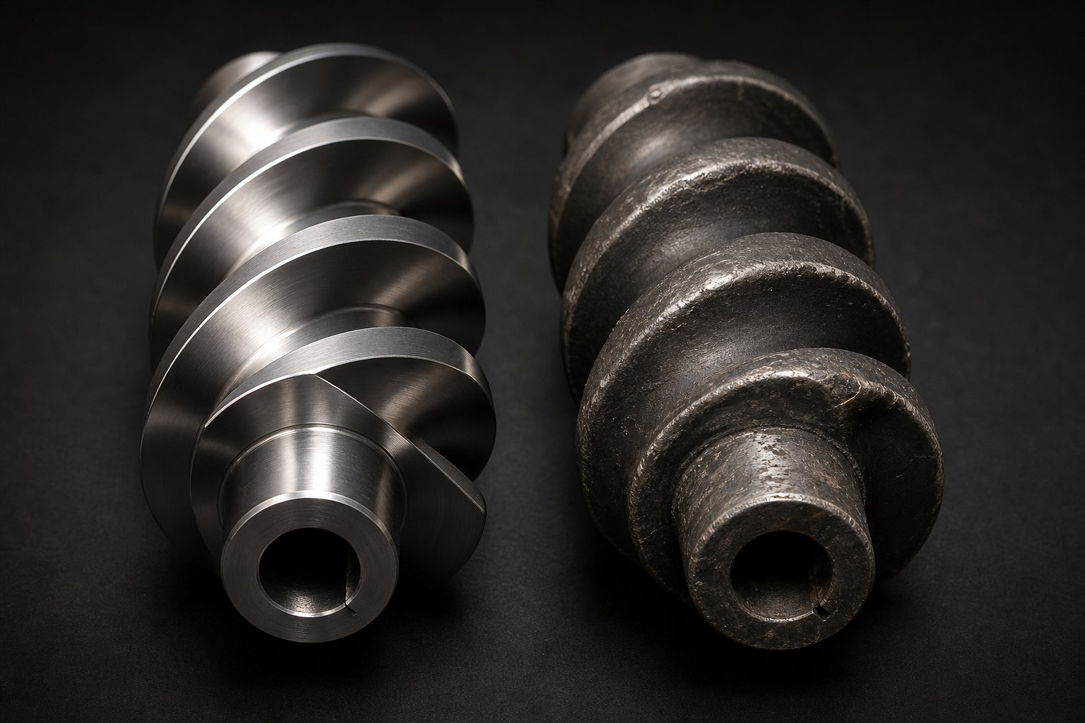
Screw Element Materials, Wear, and Surface Treatments
A perfectly designed screw profile does not stay perfect forever. Every hour of operation strips a few microns of material from flight lands, disc tips, and barrel-facing surfaces. The rate at which that erosion happens - and how long before it compromises your process - depends largely on two decisions made before the elements ever touch polymer: what substrate material they are made from, and whether any surface treatment has been applied. Extruder screw material selection is, in practice, just as consequential as stagger angle selection. Choose wisely and elements last years. Choose poorly, and you are pulling screws for inspection every few months.
Common Substrate Materials for Screw Elements
Not all steel is created equal, and the differences matter enormously when abrasive fillers, glass fibers, or mineral pigments are grinding against element surfaces at hundreds of RPM. Three broad categories cover the vast majority of screw elements in service today.
Through-hardened tool steels form the baseline. Grades like W6Mo5Cr4V2 (a high-speed tool steel common in twin-screw applications) offer a solid combination of wear resistance and toughness after heat treatment. They handle general-purpose compounding of unfilled or lightly filled polymers at a reasonable cost, making them the default choice for processors who do not regularly run highly abrasive formulations. However, their wear resistance has limits - introduce 30% glass fiber or a high loading of titanium dioxide and you will notice accelerated flight erosion within months.
Nitrided steels occupy the middle ground. Nitriding is both a surface treatment and, in some cases, a material specification - certain steel grades are specifically formulated to respond well to nitrogen diffusion, producing a hard surface case while maintaining a tougher core. The result is good surface hardness at moderate cost, suitable for applications involving moderately abrasive fillers like calcium carbonate or talc at medium loadings. Nitrided elements typically outlast untreated tool steels by a factor of 1.5 to 2 in abrasive environments, according to industry data on wear prevention.
Powder metallurgy (PM) steels sit at the top of the performance - and price - pyramid. These materials use advanced powder metallurgy processing to create exceptionally uniform microstructures with fine, evenly distributed carbide particles. That microstructural uniformity translates directly into superior screw element wear resistance, especially against aggressive abrasives like glass fiber, mineral fillers, and certain carbon black grades. Powder metallurgy screw elements can deliver two to three times the wear life of conventional tool steels, but they typically add 50 to 80 percent to the per-element cost. For high-wear applications where frequent replacements disrupt production, the math usually favors the premium material.
| Material Type | Hardness Range | Best Suited For | Relative Cost |
|---|---|---|---|
| Through-hardened tool steel (e.g., W6Mo5Cr4V2) | Moderate to high (typically 58-62 HRC after heat treatment) | General-purpose compounding, unfilled or lightly filled polymers | Low (baseline) |
| Nitrided steel | High surface hardness (65-70 HRC surface case), tougher core | Moderate abrasion: calcium carbonate, talc, medium filler loadings | Moderate (1.3-1.5x baseline) |
| Powder metallurgy (PM) steel | Very high, uniform throughout cross-section | Severe abrasion: glass fiber, mineral reinforcements, abrasive pigments | High (1.5-1.8x baseline) |
The decision often comes down to a simple cost-per-kilogram-of-product calculation. An element that costs 60 percent more but lasts three times longer in a glass-fiber-reinforced nylon application is not a premium - it is a bargain. Procurement engineers who evaluate only the purchase price per element, without factoring in replacement frequency, downtime, and quality drift, consistently overspend.
Surface Treatments and Wear Indicators
Beyond substrate selection, surface treatments add another layer of defense - sometimes literally. Three treatments dominate the market, each justified under different operating conditions.
- Nitriding (plasma or gas): Diffuses nitrogen into the element surface, creating a hard case without changing the element's dimensions. It is the most cost-effective treatment for moderate abrasion and provides good corrosion resistance. Plasma nitriding produces surface hardness in the range of 65 to 70 HRC and can extend service life by roughly 1.5 to 2 times in abrasive applications.
- Hard chrome plating: Deposits a thin chromium layer that provides excellent corrosion resistance and a low-friction surface. It is particularly useful when processing chemically aggressive materials - PVC compounds that release hydrochloric acid at elevated temperatures, for instance - but offers only moderate improvement against heavy abrasive wear.
- Tungsten carbide coating: Applied through thermal spray processes, tungsten carbide coated screw elements deliver the highest abrasive wear resistance available. These coatings create an extremely hard surface layer that resists even aggressive glass fiber and mineral filler erosion. The treatment carries a significant cost premium, but for the most demanding applications - where untreated elements would need replacement every few months - it is often the only economically viable option.
Knowing which treatment to apply matters, but equally important is knowing when elements have worn past the point of acceptable performance. Screw wear rarely announces itself with a dramatic failure. Instead, it creeps in quietly through process drift that operators may initially attribute to material variation or temperature control issues.
Watch for these practical wear indicators:
- Increased specific energy consumption: As flight lands and disc tips erode, the effective channel geometry changes. The extruder motor works harder to achieve the same output, and motor amperage at rated RPM trends upward - sometimes by 5 to 10 percent before anyone notices the product has changed.
- Declining throughput at constant screw speed: Worn conveying elements lose their volumetric efficiency. Material slips backward through widened flight clearances instead of being pushed forward. A drop below 85 percent of rated output at a given RPM is a widely used threshold for scheduling replacement.
- Product quality drift: Undispersed gels, filler agglomerates, color streaks, or inconsistent melt temperature are all signatures of elements that no longer deliver their intended shear and mixing action. By the time these defects reach the quality lab, the wear has typically been progressing for weeks.
- Melt temperature running above setpoint: Worn elements alter flow dynamics, creating localized high-shear zones that generate excess viscous heating. A persistent melt temperature overshoot of 15 degrees Fahrenheit or more above the baseline can indicate significant geometric erosion.
The underlying mechanism tying all these symptoms together is geometry change. Wear increases the clearance between the element and the barrel wall, reduces flight depth, and rounds off disc edges. Every one of those dimensional shifts degrades the element's ability to convey, shear, and seal as designed. The screw profile you carefully optimized during commissioning is, in effect, slowly redesigning itself into a less effective configuration with every hour of operation.
Tracking these indicators systematically - ideally through continuous monitoring of motor load, melt pressure, and throughput trends - transforms screw replacement from an emergency scramble into a planned maintenance event. And that predictability matters, because worn elements do not just hurt efficiency. They mask the root causes of processing problems, making it nearly impossible to troubleshoot issues like surging, poor dispersion, or die pressure instability until the worn components are identified and replaced.
Troubleshooting Common Screw Element Problems
Worn elements are one source of trouble, but they are far from the only one. Many processing headaches trace back not to degraded hardware but to a screw profile that was never quite right in the first place - or one that worked well for an old recipe and quietly fell apart when materials, throughput targets, or additive packages changed. When output starts surging, pellets come out discolored, or melt pressure swings wildly at the die, the instinct is to blame the resin, the feeder, or the barrel heaters. More often than not, though, the root cause sits on the splined shaft.
Below is a practical framework for diagnosing the most common screw-profile-related failures and linking each symptom to a specific corrective action.
Diagnosing Surging, Poor Melting, and Degradation Issues
Output surging - rhythmic fluctuation in throughput that shows up as pulsating strand thickness or cycling die pressure - is one of the most reported problems in extruder surging troubleshooting. What causes it? Picture the barrel section beneath a vent port. If the melt seal upstream of that vent is too weak - perhaps a forward kneading block is doing the job of a reverse one - the fill level underneath the port oscillates. Material alternately builds up and breaks through, creating a pressure wave that propagates all the way to the die. Worn conveying elements in the feed zone compound the issue: eroded flights lose volumetric efficiency, so material intake becomes irregular, and every gulp-and-starve cycle translates into a downstream surge. Improper feed zone pitch selection - elements too tight for the bulk density of your feedstock - can produce an identical symptom by choking intake and then releasing it in bursts.
Poor melting is equally common and often easier to diagnose visually. Unmelted particles, gels, or fisheyes in the extrudate almost always point to an inadequate melting section. The usual culprits in a poor melting in extruder screw profile scenario are insufficient kneading block length or stagger angles that are too narrow to deliver the energy input the polymer requires. A profile designed for polyethylene, for example, may leave nylon pellets partially unmelted because the crystalline phase demands significantly more shear energy to break down. Adding kneading discs, widening stagger angles from 30 degrees to 60, or introducing a 90-degree neutral block at the end of the melting section typically resolves the issue.
Degradation and discoloration present the opposite problem - too much energy rather than too little. When extrudate exits the die with a yellowish tint, brown specks, or reduced mechanical properties, the profile is likely delivering excessive shear or holding material at elevated temperatures for too long. Overly aggressive kneading blocks - long sections of 90-degree neutral or reverse-staggered discs - are the primary suspects. Too many restrictive elements stacked in series broaden the residence time distribution, guaranteeing that a fraction of the melt accumulates far more thermal history than the average. The fix is surgical: shorten the high-shear sections, replace reverse kneading blocks with forward-staggered alternatives where a full melt seal is not strictly necessary, or insert high-pitch conveying elements between restrictive zones to flush material through faster.
Resolving Die Pressure Instability and Vent Flow
Die pressure instability in extrusion - slow drifts or rapid swings in melt pressure at the die head - frustrates downstream operations because it directly causes dimensional variation in the final product. Common troubleshooting guidance focuses on die blockages or feeder calibration, but screw elements are frequently the hidden culprit. An inadequate pressure-building zone - too few tight-pitch conveying elements, or elements that have worn past their effective clearance - simply cannot generate the consistent forward pressure the die demands. Extending the metering zone by adding one or two additional 0.5D-pitch conveying segments often stabilizes pressure immediately.
The twin screw extruder vent flow problem - molten polymer climbing out through the vacuum port - is arguably the most disruptive failure mode in devolatilization. The cause is almost always a compromised melt seal upstream of the vent. As detailed analysis of vent flooding confirms, the degassing zone is designed to be a partially filled, low-pressure region. If forward-conveying elements beneath the port lack sufficient volumetric capacity, or if the upstream restrictive elements fail to create a complete seal, the fill level rises until melt escapes through the only available opening. The corrective action is twofold: install or replace the upstream seal with a proper reverse kneading block or blister ring, and verify that the conveying elements directly under the vent port use a pitch large enough to keep the zone partially starved - typically 1.5D or greater.
The following table consolidates these scenarios into a quick-reference format you can keep on hand during profile changes or process audits:
| Symptom | Likely Screw Element Cause | Corrective Action |
|---|---|---|
| Output surging (cyclic throughput fluctuation) | Insufficient melt seal upstream of vent; worn or improperly pitched feed zone conveying elements | Replace forward kneading blocks at seal location with reverse kneading blocks or blister ring; verify feed zone pitch matches feedstock bulk density; inspect conveying elements for wear |
| Poor melting (unmelted particles, gels, fisheyes) | Kneading block section too short; stagger angles too narrow for polymer's energy requirement | Add kneading discs to lengthen the melting section; widen stagger angles (e.g., 30° to 60°); add a 90° neutral block at the end of the melting zone |
| Degradation and discoloration | Overly aggressive kneading blocks (extended 90° or reverse sections); too many restrictive elements in series | Shorten high-shear kneading sections; replace reverse blocks with forward-staggered where full seal is unnecessary; insert high-pitch conveying elements between restrictive zones |
| Die pressure instability | Inadequate metering zone length; worn tight-pitch conveying elements losing volumetric efficiency | Extend metering zone with additional 0.5D-pitch conveying segments; replace worn metering elements |
| Vent flow (melt escaping through vacuum port) | Weak or absent melt seal upstream of vent; insufficient conveying capacity beneath the vent port | Install reverse kneading block or blister ring upstream of vent; use large-pitch (1.5D+) conveying elements directly under the port to maintain partial fill |
Notice a pattern across all five scenarios: every corrective action involves changing or repositioning specific elements on the shaft. Temperature adjustments and speed changes may mask the symptom temporarily, but the permanent fix almost always lives in the screw profile itself. That reality reinforces a broader truth - selecting the right elements is not a one-time commissioning exercise. It is an ongoing discipline that shifts with every new formulation, throughput target, or application your extruder is asked to handle.
Selecting Screw Elements for Specific Applications
Every formulation tells you what it needs - if you know how to listen. A calcium carbonate filler compound practically screams for dispersive shear after the side feeder. A color masterbatch whispers for distributive finesse that spreads pigment without destroying it. A recycled post-consumer flake demands flexibility because tomorrow's feedstock will look nothing like today's. The principles covered so far - stagger angles, zone sequencing, RTD control, wear resistance - all converge in application-specific element selection. This is where theory meets the production floor.
Element Selection for Compounding, Pelletizing, and Masterbatch
Compounding filled systems - think calcium carbonate at 60 to 80 percent loading, talc-reinforced polypropylene, or glass-fiber-reinforced nylon - places the heaviest demands on screw elements for a compounding extruder. The filler usually enters through a side feeder downstream of the melting zone, landing in already-molten polymer. From that injection point forward, the profile needs aggressive dispersive mixing to break agglomerate clusters and wet the filler surfaces into the melt. Industry practice positions kneading blocks with 60- or 90-degree stagger angles immediately after the side feed port, where the filler concentration is highest and agglomerates are still intact. As compounding process engineers have documented, the kneading block layout in this post-feed section is the single most consequential configuration decision for dispersion quality - wrong placement or insufficient shear here leads to filler clumps that no amount of downstream mixing can fix.
A critical companion requirement for high-filler compounding is atmospheric venting. Side-fed fillers - especially low-bulk-density powders like calcium carbonate - drag enormous volumes of entrained air into the barrel. Without vents positioned near the feed point, that trapped air disrupts melt flow, causes surging, and creates voids in the final product. Industry guidance on compounding extruders confirms that loadings above 50 percent typically require multiple atmospheric vents to handle the displaced air volume. The screw profile must accommodate these vents with partially filled conveying zones - wide-pitch elements that keep the barrel un-pressurized at the vent opening.
Glass-fiber-reinforced compounds add a twist. You need enough shear to wet the fibers into the matrix, but too much dispersive energy shatters them, destroying the mechanical properties you are trying to build. Twin screw elements for filled polymers in fiber applications tend to favor gentler distributive mixing elements - toothed geometries like ZME or TME - rather than the high-shear kneading blocks that work well for particulate fillers. Side feeding the fiber downstream of the melting zone also protects fiber length by keeping it away from the aggressive melting-section kneading blocks.
Masterbatch production shifts the emphasis. In a masterbatch extrusion screw configuration for color concentrates, the overriding goal is pigment dispersion - breaking every last agglomerate down to primary particle size so the final letdown ratio produces streak-free, shade-consistent parts. This demands well-placed dispersive kneading blocks, but with a caveat: many organic pigments are heat-sensitive. Push shear intensity too high and you degrade the colorant itself. The practical approach uses a split-feed strategy - introducing pigment separately from the carrier resin - followed by a mixing section that ramps shear progressively (30-degree to 60-degree kneading blocks) rather than slamming the pigment with neutral or reverse blocks from the start. Distributive mixing elements downstream then spread the dispersed pigment uniformly through the melt, ensuring concentration homogeneity across the pellet cross-section.
Functional masterbatch - additives like UV stabilizers, flame retardants, or processing aids blended into a carrier - leans even more heavily toward distributive mixing. These actives often have narrow thermal processing windows and can lose efficacy if over-sheared. Toothed mixing elements and narrow-angle kneading blocks dominate these profiles, keeping energy input low while maximizing spatial redistribution.
Pelletizing applications may seem straightforward, but element selection in the metering zone is critical. Stable die pressure is non-negotiable for consistent pellet weight and geometry. Tight-pitch conveying elements - typically 0.4D to 0.5D - must span enough barrel length to build the pressure cushion that absorbs minor upstream fluctuations. Worn or too-short metering sections produce the pressure swings that show up as oversized and undersized pellets in the same batch. If your pelletizer is cutting inconsistently, the first place to look is not the cutter head - it is the last few elements before the die.
Modular Screw Segments for Recycling Applications
Recycling is where screw design for plastic recycling gets genuinely difficult - and where modularity pays its biggest dividends. Unlike virgin compounding, where feedstock arrives with a consistent melt flow index, moisture content, and contaminant profile, post-consumer recycled (PCR) streams are inherently variable. One lot of regrind might be relatively clean HDPE bottle flake. The next could be a mixed-polyolefin stream contaminated with adhesive residues, printing inks, and residual food-contact solvents. A fixed screw profile that works perfectly for one lot may underperform or overprocess the next.
Co-rotating twin-screw extruders have become the equipment of choice for recyclers precisely because their modular screw architecture lets operators reconfigure the profile as feedstock quality shifts. When a batch arrives with higher moisture or volatile content, you can add an extra melt seal and vacuum vent stage. When the next batch is cleaner but needs filler reinforcement to restore mechanical properties lost during prior use cycles, you swap in side-feed conveying sections and dispersive kneading blocks. That adaptability is not a luxury in recycling - it is a survival requirement.
Devolatilization is especially demanding in recycling applications. Post-consumer plastics often carry volatile organic compounds (VOCs), residual solvents, and moisture that must be removed to meet downstream quality standards - particularly in automotive and food-contact applications where odor and fogging specifications are strict. Effective contaminant removal requires well-sealed vent zones: reverse kneading blocks or blister rings creating tight melt dams upstream, with wide-pitch conveying elements beneath the vacuum port to maximize free melt surface for volatile extraction. Some recycling lines run up to four devolatilization stages in series to achieve the required purity levels, which demands an L/D ratio of 44:1 or beyond and a carefully sequenced element layout that balances volatile removal with throughput.
Compatibilization adds another layer of complexity. Mixed-polymer recycling streams - multi-layer film waste, commingled rigid packaging - often contain immiscible polymer phases that need to be blended into a usable alloy. Compatibilizer additives introduced via side feeding require their own mixing section downstream: enough dispersive energy to activate the compatibilizer at the polymer interface, followed by distributive elements that spread the modified phase morphology uniformly. This is reactive processing territory, where RTD control matters just as much as shear intensity.
For processors managing this kind of application diversity - compounding one day, masterbatch the next, recycled feedstock the day after - having access to a comprehensive inventory of interchangeable elements becomes a practical necessity. Suppliers like NANHAIYA offer modular segment screws along with the full range of conveying elements, kneading blocks, and specialty mixing components needed to reconfigure profiles across compounding, pelletizing, masterbatch, and recycling applications. The ability to source all element types from a single supplier simplifies inventory management and ensures dimensional consistency when mixing and matching components on the same shaft.
Regardless of application, the underlying logic remains the same: the formulation dictates the element layout, not the other way around. Match each zone to its processing objective, select elements with the appropriate geometry and wear resistance, and maintain the flexibility to reconfigure when the job changes. That discipline is what separates a production line that adapts to market demands from one that fights its own screw profile every shift.
Yet even the best element selection strategy falls short without a reliable way to source, stock, and replace components as they wear or as recipes evolve - a supply-side challenge that deserves its own practical framework.
Building a Reliable Screw Element Supply Strategy
A well-optimized screw profile is only as reliable as your ability to maintain it. Kneading blocks wear down, conveying elements lose their edge, and new formulations demand profile changes that your current inventory may not support. When that moment arrives - and it always does - the difference between a four-hour element swap and a four-week production shutdown comes down to one thing: how well you planned your supply strategy before you needed it.
This final section addresses the practical, often-overlooked logistics that keep twin-screw extruders running: dimensional compatibility, sourcing decisions, and screw element inventory management that protects both uptime and budget.
Interchangeability, Spline Standards, and OEM Considerations
Here is a misconception that costs processors real money: assuming that any element with the same nominal screw diameter will fit their machine. In reality, screw element spline compatibility is far more nuanced than a single diameter number suggests.
Different extruder OEMs - Coperion, Leistritz, KraussMaffei Berstorff, JSW, and others - each use their own spline profiles, outer-to-inner diameter ratios (OD/ID), element lengths, and shaft interface geometries. A 40 mm element designed for one manufacturer's shaft will not necessarily slide onto another's, even if both machines are marketed as "40 mm twin-screw extruders." As experienced replacement suppliers have documented, even machines with the same nominal screw diameter may use different spline structures, effective lengths, segment interfaces, and center distances - making blind cross-referencing risky.
What does this mean for procurement? When sourcing replacement screw elements for a twin screw extruder - whether from the original OEM or an aftermarket supplier - you need to verify several critical dimensions before placing an order:
- Outer diameter (OD) and inner bore diameter (ID): The OD/ID ratio defines the element's cross-sectional geometry and must match the barrel bore and shaft precisely. Even a fraction of a millimeter off can cause binding, excessive clearance, or premature wear.
- Spline profile: The internal keyway pattern that locks the element to the shaft. Involute splines, straight-sided splines, and proprietary profiles are all in use across the industry. A mismatched spline means the element simply will not mount.
- Element length: Modular screw builds rely on elements adding up to a specific total length. An element that is 2 mm too long or too short throws off the entire assembly.
- Center distance: The spacing between the two parallel screw bores in the barrel. This dimension governs how the intermeshing element profiles interact and must be matched exactly.
Many processors who purchased their extruder years ago - or acquired it secondhand - discover that original drawings and specification sheets have been lost. In those cases, sending physical samples of worn elements to the supplier for direct measurement is often the safest path to accurate reproduction. Photos, nameplate data, and rough measurements help, but nothing substitutes for a hands-on dimensional inspection when compatibility is uncertain.
The good news is that reputable aftermarket extruder screw elements suppliers design their products to be compatible with the major OEM platforms. This gives processors a second sourcing channel - often at lower cost and shorter lead times than going back to the original machine manufacturer. The key is to work with a supplier who asks the right questions upfront: extruder brand and model, shaft diameter, spline details, and ideally a sample element for verification. A supplier who quotes based on screw diameter alone, without requesting these specifics, is a red flag.
Building a Smart Screw Element Inventory
Imagine your highest-volume production line goes down on a Friday afternoon because a kneading block in the melting zone has worn past its effective clearance. You do not have a replacement on the shelf. The supplier quotes a two- to four-week lead time. Every day of downtime costs thousands in lost production - far more than the element itself would have cost sitting in a cabinet.
This scenario plays out constantly across the industry, and it is entirely preventable. Maintenance planning data consistently shows that stocking critical spares - the components most likely to fail or wear out - costs a fraction of a single day's lost production. The challenge is deciding what to stock without tying up excessive capital in parts that may sit unused for years.
A practical rule applies: prioritize elements that see the most abrasion, the highest shear, or the most frequent reconfiguration. Kneading blocks in the melting and mixing zones wear fastest because they operate under the highest mechanical loads. Restrictive elements - reverse kneading blocks and blister rings - face similar stress. Conveying elements in the metering zone erode steadily under pressure-driven flow. These are your critical spares.
Here is a step-by-step approach to building an effective inventory:
- Document every screw profile currently in use. Create a written or digital map for each product recipe, listing every element on the shaft in order - type, geometry, length, material grade, and position. This profile map is your single most important maintenance document. Without it, rebuilding a screw after a teardown becomes guesswork.
- Identify wear-critical positions. Review your profile maps and flag the elements that sit in high-shear zones (kneading blocks at 60 degrees or above), pressure-building zones (tight-pitch metering elements), and melt seal zones (reverse kneading blocks, blister rings). These are the positions where wear will force replacement first.
- Stock at least one spare set of each wear-critical element. For kneading blocks, keep duplicates in the stagger angles and disc counts you use most frequently. For conveying elements, stock spares in the two or three pitch sizes that appear most often across your profiles - typically a large-pitch (1.5D) and a tight-pitch (0.5D) variant.
- Track wear rates by position and formulation. After each screw pull, measure and record element dimensions at the wear-critical positions. Over time, this data reveals which elements degrade fastest and which formulations are most abrasive - allowing you to predict replacement needs rather than react to failures.
- Establish a reliable supplier relationship before you need it. Qualifying aftermarket suppliers, verifying dimensional compatibility, and confirming lead times should happen during normal operations - not during an emergency. Suppliers like NANHAIYA, who provide the full range of modular segment screws, kneading blocks, and conveying elements compatible with major twin-screw extruder platforms, give processors the flexibility to source all element types from a single vendor. This simplifies ordering, ensures consistent dimensional standards across the inventory, and reduces the risk of compatibility mismatches when mixing components from multiple sources.
- Budget for element replacement as an operating cost, not an emergency expense. Industry recommendations suggest allocating 2 to 3 percent of the extruder's capital value annually for maintenance and spare parts. Treating element replacement as a predictable line item - rather than a surprise capital request - keeps procurement cycles smooth and prevents the false economy of delaying replacements until quality or throughput has already suffered.
One final point worth emphasizing: always verify dimensional compatibility with any supplier, whether OEM or aftermarket. Request a first-article inspection report on initial orders, and if possible, perform a physical fit check on a spare shaft before committing elements to a production build. The few hours invested in verification save weeks of frustration if a dimensional mismatch reaches the production floor undetected.
Screw elements may be small components relative to the extruder as a whole, but they carry outsized influence over product quality, process stability, and operating cost. The processors who treat them as strategic assets - understanding their geometry, maintaining their condition, and planning their supply - consistently outperform those who treat them as commodity hardware. Every topic covered in this article, from stagger angle selection to zone mapping to wear management, points to the same conclusion: mastering these modular components is the shortest path to mastering the extrusion process itself.
Frequently Asked Questions About Screw Elements
1. What are screw elements and what do they do in an extruder?
Screw elements are modular components that slide onto a splined shaft inside a twin-screw extruder barrel. Each element has a unique geometry — defined by pitch, disc angle, or tooth pattern — that performs a specific processing function such as conveying, melting, mixing, devolatilizing, or pressurizing the polymer melt. By rearranging elements on the shaft, engineers can completely change how material is processed without replacing the entire screw, making them the primary tool for optimizing extrusion performance across applications like compounding, masterbatch, and recycling.
2. How does kneading block stagger angle affect mixing and shear?
The stagger angle is the rotational offset between successive elliptical discs in a kneading block. Narrower angles like 30 degrees provide high forward conveying with low shear, suitable for gentle melting. As the angle widens to 60 degrees, shear intensity increases significantly while forward conveying drops. At 90 degrees (neutral), forward conveying is zero and shear reaches its maximum — ideal for breaking agglomerates. Reverse-staggered kneading blocks push material backward, creating the most intense mixing and acting as melt seals. Engineers often use a progressive sequence (30 to 60 to 90 degrees) to ramp shear gradually and avoid feed instability.
3. What causes vent flow in a twin-screw extruder and how do you fix it?
Vent flow — molten polymer escaping through the vacuum port — is almost always caused by an inadequate melt seal upstream of the vent opening. Without a proper seal created by reverse kneading blocks or a blister ring, the fill level beneath the vent rises until melt escapes through the port. To fix this, install or replace the upstream seal element with a reverse kneading block or blister ring, and ensure the conveying elements directly under the vent use a large pitch (1.5D or greater) to keep that zone partially starved and at low pressure.
4. How do I choose the right screw element material for abrasive compounds?
Material selection depends on the abrasiveness of your formulation. Standard through-hardened tool steels work well for unfilled or lightly filled polymers at baseline cost. Nitrided steels offer improved surface hardness for moderately abrasive fillers like calcium carbonate or talc. For severe abrasion from glass fiber, mineral reinforcements, or aggressive pigments, powder metallurgy (PM) steels provide two to three times the wear life of conventional tool steels. Surface treatments such as tungsten carbide coating add further protection in the most demanding applications. Suppliers like NANHAIYA (nhyscrews.com) offer modular screw segments in various material grades to match specific wear requirements.
5. Are screw elements interchangeable between different extruder brands?
No, screw elements are not universally interchangeable. Different extruder OEMs use proprietary spline profiles, outer-to-inner diameter ratios, element lengths, and center distances. A 40 mm element designed for one manufacturer's shaft may not fit another's machine even if both are labeled as 40 mm extruders. When sourcing replacements — whether from the original OEM or an aftermarket supplier — you must verify the spline profile, OD/ID ratio, element length, and center distance. Sending a physical sample element for dimensional inspection is the safest approach when original specifications are unavailable.
Written by
Nanhaiya Technical Team
Zhoushan Nanhaiya Plastic Machinery Co., Ltd.
The Nanhaiya technical team supports screw and barrel manufacturing projects through application review, technical communication, custom manufacturing coordination, and production and quality control.
Discuss Your Application
Related Articles
More insights on screw barrel technology and plastics processing.

Extruder Machine Decoded: From Raw Pellet To Finished Product
Oct 6, 2026
Learn how an extruder machine works, compare single-screw vs. twin-screw types, and get expert guidance on specs, troubleshooting, and selection.
Read Article
PE Pipe Making Machine Decoded: From Raw Resin to Flawless Pipe
Oct 4, 2026
Learn how a PE pipe making machine works, from resin to finished pipe. Covers components, material grades, automation, troubleshooting, and buyer selection tips.
Read Article
PVC Profile Making Machine Decoded: From Raw Resin To Profit
Oct 3, 2026
Learn how a PVC profile making machine works — extrusion process steps, key technical parameters, die design, calibration methods, maintenance, and total cost of ownership.
Read ArticleLooking for something else?
Search by material, symptom or product and jump straight to the relevant page.
These are navigation suggestions based on keyword matching — not a quotation, not a delivery commitment, and not a substitute for engineering review. Final specification is confirmed by our engineers against your drawings and processed material.
Need help with screw barrel selection?
Share your machine model, processed material and application. Our team can help with pricing and technical support.