


什么是挤出机?它为什么重要?
如果你曾经用裱花袋挤过糖霜,或者用压面机揉过面团,那么你已经了解了挤出机的基本原理。工业挤出机只是在更高的温度、压力和速度下完成同样的工作——将原材料(例如颗粒、粉末或粉末)加工成连续的形状,最终成为我们日常生活中使用的管道、薄膜、型材和电缆。
挤出机定义和核心概念
那么,挤出机究竟是什么呢?简单来说,挤出机是一种利用旋转螺杆将原材料(通常是热塑性聚合物)推入加热料筒,然后将熔化的物料挤压通过称为模头的成型开口的机器。最终得到的是具有一致横截面的连续型材。
挤出机是一种制造设备,它利用加热料筒内的一个或多个旋转螺杆来熔化、均质化原材料,并将原材料通过成型模具挤出,从而以可控的速度生产连续的型材、管道、薄膜或其他形状的产品。
上述对挤出机的定义涵盖了其核心机械原理,但挤出机的实际意义远不止于此。这台单一设备能够一次性完成进料、熔化、混合和加压等工序,取代了以往需要多个批次步骤才能完成的生产流程。正是这种连续输出和精确控制的结合,使得螺杆挤出机在塑料、食品、橡胶乃至制药等行业中都不可或缺。
从冲压机到智能挤出机——简史
想知道挤出机在历史语境中的含义吗?这个概念的历史比大多数人想象的要悠久得多。最早的聚合物加工设备是间歇式混合机和柱塞式压机,而第一台大型混合设备——双辊轧机——的描述则出现在1836年的一项专利中。柱塞式挤出机利用液压将物料分批挤出通过模头,但其一致性和产量都有限。
19世纪中后期,单螺杆泵装置开始应用于肥皂和陶瓷等产品的生产。1879年,格雷获得了一项具有里程碑意义的英国专利,该专利引入了用于电线涂层的螺杆挤压技术,并指出其绝缘质量优于任何冲压装置所能生产的产品。值得注意的是,该专利强调产品质量而非生产速度——这表明,从一开始,推动创新的就是产品的一致性,而不仅仅是产量。
Single-screw designs dominated through the mid-twentieth century, but the 1970s marked a tipping point as twin-screw extruders proved their superior mixing capability. By the 1980s, the twin-screw configuration had become the preferred continuous mixer for compounding applications. Today, modern extruder machines integrate servo-driven motors, modular barrel segments with independent temperature zones, and Industry 4.0-ready controls featuring real-time monitoring, recipe management, and predictive maintenance algorithms.
Whether you are a newcomer trying to grasp what is a extruder or an engineer evaluating your next capital purchase, understanding how these machines evolved reveals why certain design choices - screw geometry, barrel modularity, digital controls - exist in the first place. That foundation becomes especially valuable once you look inside the barrel and follow what actually happens to raw material as the screw turns.
How an Extruder Machine Works Step by Step
Imagine dropping a handful of plastic pellets into one end of a machine and watching a perfectly shaped pipe, film, or profile emerge from the other. That transformation happens in a matter of seconds, yet the physics inside the barrel follow a precise, zone-by-zone sequence. Understanding this sequence is the key to controlling output quality, diagnosing problems, and getting the most from any extrusion machine.
Feed, Compression, and Metering Zones Explained
Every screw extrusion system divides the barrel into three functional zones, each with a distinct job.
Feed zone. Raw pellets or powder drop from the hopper into the deepest section of the screw channel. Here, the flights act like a conveyor, grabbing solid material and pushing it forward. The channel is deliberately deep so it can accept a large volume of uncompacted granules. A water-cooled feed throat keeps temperatures low enough to prevent pellets from softening too early, which would cause them to stick and bridge rather than flow. Consistent feeding at this stage is critical - even small interruptions ripple downstream as pressure swings and weight variation in the finished product.
Compression (transition) zone. As material advances, the screw channel gradually becomes shallower. This shrinking space compacts the pellets together, squeezing out trapped air and forcing polymer surfaces into tighter contact with the heated barrel wall. Friction between pellets and between the polymer and barrel generates significant mechanical heat. Combined with external heater bands, this energy initiates melting. In fact, shear heating from the extruding action - not the barrel heaters alone - provides the majority of the thermal energy needed to liquefy most polymers. The compression zone is where the solid bed steadily converts into a growing melt pool, and its design has the single largest influence on melt quality.
Metering zone. By this stage, the polymer should be fully molten. The channel depth is at its shallowest, creating high pressure and ensuring a uniform, homogeneous melt is delivered to the die at a steady rate. Consistent pressure here translates directly into consistent dimensions and weight in the final product. If unmelted particles or temperature variations survive into this zone, they will show up as defects downstream - gels, rough surfaces, or dimensional drift.
The Role of the Screw, Barrel, and Die Assembly
The screw is the heart of the extruding machine. Its geometry - specifically flight depth, pitch, and compression ratio - dictates how aggressively material is conveyed, compacted, and sheared. A deeper feed section grabs more material per revolution, while a shallower metering section builds the pressure needed to push melt through the die. The compression ratio, calculated by dividing feed-zone channel depth by metering-zone channel depth, must be matched to the polymer's bulk density and melting behavior. A ratio that is too aggressive can overshear heat-sensitive materials like PVC; one that is too gentle may leave unmelted particles in the output.
The barrel surrounds the screw and provides the heated surface against which melting begins. Multiple independently controlled temperature zones along its length let operators fine-tune the thermal profile to suit different polymers - hotter in the compression zone to assist melting, slightly cooler near the die to stabilize viscosity.
Here is the component sequence that every pellet passes through on its way to becoming a finished product:
- Hopper - stores and feeds raw material into the barrel
- Screw - conveys, compresses, and melts the polymer
- Barrel - provides the heated chamber and containment
- Breaker plate and screen pack - filters contaminants, builds back-pressure, and eliminates rotational memory in the melt
- Die - shapes the homogeneous melt into the desired cross-section
The die is where the extrusion extruder delivers its visible result. Whether it is a flat slot for sheet, an annular gap for pipe, or a complex profile for a window frame, the die's internal geometry must distribute melt evenly across its opening. Uneven flow creates thickness variation, warping, or surface defects.
Screw and barrel condition directly affects output stability and melt consistency. Even modest wear - a few tenths of a millimeter of flight-tip erosion - reduces compression, shifts the melting zone downstream, and introduces the kind of variability that no amount of temperature adjustment can fully compensate for.
Every parameter discussed here - zone temperatures, screw speed, back-pressure, compression ratio - interacts with the others. Changing one shifts the balance across the entire system. That interconnectedness is precisely why different applications demand different machine configurations, a subject that becomes especially clear when you compare the two dominant extruder architectures side by side.
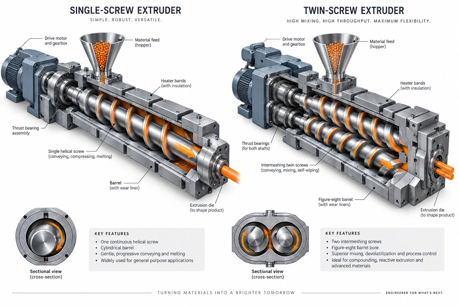
Types of Extruder Machines Compared
Not every extrusion job calls for the same hardware. A plant running miles of polyethylene pipe has very different demands than a compounder blending carbon nanotubes into a polymer matrix. So what are extruders actually available in, and how do you pick the right architecture? The answer comes down to two dominant designs - single-screw and twin-screw - plus a couple of specialized alternatives worth knowing about.
Single-Screw Extruders - Strengths and Best Uses
The single-screw plastic extruder is the workhorse of the industry for good reason. It is mechanically straightforward: one screw rotating inside one barrel, with relatively few wear parts and a lower purchase price compared to multi-screw alternatives. For well-characterized polymers like PE, PP, and PET - materials whose melting and flow behavior are predictable - a single-screw design delivers reliable throughput with minimal fuss.
You will find these machines dominating profile extrusion for window frames and trim, pipe production, sheet and film lines, and wire coating. Their strength lies in efficient pressure generation and steady melt delivery when the feedstock does not require intensive mixing. Maintenance is comparatively simple, spare parts are widely available, and operators can learn the system quickly. If your application involves pumping a consistent material into a well-defined shape, a single-screw industrial extruder is usually the most cost-effective choice.
Twin-Screw Extruders - Co-Rotating vs. Counter-Rotating
Twin-screw extruders place two intermeshing screws side by side inside a figure-eight barrel bore. This arrangement unlocks mixing and compounding capabilities that a single screw simply cannot match - but the two sub-types serve distinctly different purposes.
Co-rotating twin-screw extruders spin both screws in the same direction. The fully intermeshing, self-wiping geometry creates intense shear fields between the screws and between the screw and barrel, producing complex deformation histories that break up filler agglomerates and control phase morphology in polymer blends. Because the screw elements can be rearranged modularly, engineers can fine-tune where and how much energy is applied to the material. Typical applications include compounding with inorganic and organic fillers, producing polymer alloys, and reactive extrusion involving polymerization or compatibilization. If you are processing nanocomposites, recycled blends, or any recipe that demands thorough distributive and dispersive mixing, co-rotating is the default choice.
Counter-rotating twin-screw extruders spin their screws in opposite directions. At the intermeshing zone, material is drawn in and compressed rather than sheared, producing a calendering effect that disperses additives under relatively gentle conditions. Shear heating stays low, and the machine operates effectively at high fill levels and low screw speeds. This makes it ideal for thermally sensitive materials like rigid PVC, which has a narrow window between melting and degradation. Counter-rotating plastic extruders are widely used for PVC pipes, sheets, and profile extrusion products where holding a low processing temperature is non-negotiable.
Beyond these two main families, a couple of niche designs fill specialized roles. Ram extruders use a hydraulic piston rather than a rotating screw to push material through a die. They handle ultra-high-viscosity compounds such as PTFE and certain rubber formulations that would stall a screw-based system. Output is batch-based rather than continuous, so throughput is limited. Planetary roller extruders feature a central main spindle surrounded by several smaller planetary spindles that orbit inside an internally toothed barrel. The large surface area and gentle rolling action provide excellent temperature control and mixing at very low shear, making them popular for heat-sensitive PVC calendering compounds and thermally reactive adhesive formulations.
Quick Comparison at a Glance
Choosing between extruders is easier when you can see their strengths and trade-offs side by side. The table below maps the two dominant types across the factors that matter most during selection.
| Factor | Single-Screw Extruder | Twin-Screw Extruder (Co-Rotating) | Twin-Screw Extruder (Counter-Rotating) |
|---|---|---|---|
| Mixing Ability | Moderate - adequate for pre-compounded materials | Excellent - intense dispersive and distributive mixing via kneading blocks | Good - gentle dispersive mixing through calendering effect |
| Material Flexibility | Best for well-characterized, consistent feedstocks | Handles filled, reactive, recycled, and multi-component formulations | Optimized for thermally sensitive materials like rigid PVC |
| Capital Cost | Lower | Higher | Moderate to higher |
| Maintenance | Simpler - fewer wear parts, straightforward screw removal | More complex - modular screw elements require careful assembly and inspection | Moderate - less complex than co-rotating but more than single-screw |
| Throughput Range | Wide - from small lab units to high-volume production lines | Wide - scalable from 6 mm lab extruders to large production machines | Moderate - typically matched to profile and pipe line speeds |
| Common Applications | Pipe, profile, sheet, film, wire coating | Compounding, polymer alloys, reactive extrusion, masterbatch, nanocomposites | PVC pipe, PVC profile, PVC sheet |
Notice a pattern? The single-screw design excels at forming, while twin-screw configurations shine at mixing and compounding. Many large-scale plastic extruders operations actually use both: a twin-screw compounder prepares the material, and a single-screw line shapes it into the final product.
Knowing which machine type fits your application is only half the equation, though. The real performance differences emerge in the technical specifications - screw diameter, L/D ratio, motor torque, and zone control - that determine whether a given extruder can actually hit your throughput, quality, and efficiency targets.
Key Technical Specifications Engineers Should Know
Reading an extruder machine datasheet for the first time can feel like decoding a foreign language - L/D ratios, compression ratios, torque curves, and zone counts all compete for your attention. Yet every one of these numbers tells you something concrete about what the machine can and cannot do. Understanding them is the difference between specifying equipment that hits your targets and buying a machine that underperforms from day one. Let's break each parameter down into plain, practical terms.
Screw Geometry Specs - L/D Ratio, Diameter, and Compression Ratio
Screw diameter is the single biggest indicator of an extruder's throughput scale. Measured across the outermost edge of the screw flights, it determines how much material the screw can grab and push forward with each revolution. Here is the critical detail: extrusion volume is roughly proportional to the square of the diameter. That means a modest jump - say, from a 60 mm to a 90 mm screw - does not increase output by half; it nearly doubles it. When engineers size an extrusion system, diameter is typically the first specification they lock down because it frames every other decision.
L/D ratio (length-to-diameter ratio) describes how long the screw is relative to its diameter. A higher L/D ratio gives the polymer more time inside the barrel, which improves melt homogeneity and allows for better heat distribution throughout the material. Common values fall in the 20:1 to 30:1 range, but that bracket is a starting point rather than a rigid rule. Thermally sensitive polymers like PVC often perform best with a shorter L/D ratio to minimize residence time and the risk of degradation, while materials requiring higher processing temperatures and pressures benefit from a longer screw. Pre-pelletized feedstocks that have already seen some processing history can typically get away with a shorter screw, whereas unprocessed powders need the extended residence time of a higher L/D ratio for proper melting and homogenization.
Compression ratio compares the volume of the first screw groove in the feed section to the last groove in the metering section. It must match the material's bulk density - essentially bridging the gap between the loose density of incoming pellets or powder and the solid density of the finished melt. A higher compression ratio facilitates thorough plasticization and densification, but the optimal value is material-dependent. For example, polyethylene typically requires a compression ratio of 3:1 to 4:1, polypropylene ranges from 2.5:1 to 4:1, and ABS sits lower at 1.6:1 to 2.5:1. Getting this wrong means either overshearing sensitive resins or leaving partially unmelted material in the output stream.
Drive and Thermal Parameters - Torque, RPM, and Zone Control
Motor power and torque govern how much mechanical energy the screw can deliver to the polymer. Torque is what actually turns the screw against the resistance of compacting and shearing material, while power (measured in kW or HP) sets the upper limit of the work the drive can sustain. When you increase L/D ratio and push screw speed higher, torque demand climbs accordingly - and for smaller-diameter screws, a stress analysis becomes essential to confirm the screw can handle that load without mechanical failure. Undersized drives lead to stalling, speed limitations, and the inability to process higher-viscosity materials.
Screw speed (RPM) directly controls output rate and shear intensity. Faster rotation pushes more material through the machine extrusion process per unit of time, but it also increases frictional heating. For shear-sensitive polymers, running too fast can degrade the material before it ever reaches the die. The practical operating window depends on the interplay between screw geometry, polymer viscosity, and cooling capacity - there is no universal "best" RPM.
Number of heating and cooling zones determines how precisely you can shape the thermal profile along the barrel. Modern extrusion systems typically feature four to six independently controlled zones, though some machines offer ten or more. Each zone uses heater bands for warming and air or water channels for cooling, allowing operators to set a rising, flat, or peaked temperature profile tailored to the polymer's softening point, crystalline melting temperature, and target processing temperature. Independent zone control is not a luxury - it is what lets the same machine handle HDPE one shift and nylon the next without compromising melt quality. As a practical note, the temperatures displayed by zone controllers often do not match the actual melt temperature; the real mass temperature is typically higher than the set points, so experienced operators learn to apply intentional corrections.
Throughput capacity ties all the above parameters together into the number that matters most on the production floor: kilograms (or pounds) of finished product per hour. It is a function of screw diameter, L/D ratio, screw speed, compression ratio, and the material's melt behavior - no single spec determines it in isolation.
The table below consolidates these specifications into a quick-reference format so you can evaluate any extruder tech datasheet at a glance.
| Specification | Unit | Practical Significance | Typical Range Considerations |
|---|---|---|---|
| Screw Diameter | mm (or in) | Primary determinant of throughput scale; output scales with the square of diameter | Lab: 15-30 mm; Production: 45-150 mm+ |
| L/D Ratio | Dimensionless (e.g., 24:1) | Affects residence time, melt homogeneity, and mixing quality | Common range: 20:1 to 30:1; shorter for heat-sensitive polymers, longer for demanding materials |
| Compression Ratio | Dimensionless (e.g., 3:1) | Must match material bulk density; controls compaction and melt quality | PE: 3-4; PP: 2.5-4; PVC granules: 2-3; ABS: 1.6-2.5 |
| Motor Power | kW or HP | Sets the maximum sustainable work input; limits top throughput and material viscosity range | Scales with screw diameter and intended output rate |
| Motor Torque | Nm | Determines the screw's ability to turn against material resistance; critical for startup and high-viscosity compounds | Must be verified against screw stress limits, especially for smaller diameters |
| Screw Speed (RPM) | rev/min | Controls output rate and shear input; higher RPM increases throughput but raises frictional heating | Typical production: 50-150 RPM; varies widely with material sensitivity |
| Heating/Cooling Zones | Count | More zones enable finer thermal profiling for different polymers and tighter quality control | Standard: 4-6 zones; complex applications: up to 10+ |
| Throughput Capacity | kg/h or lb/h | Net production rate; a function of all other specifications combined | Determined by diameter, RPM, L/D, material properties, and die resistance |
You will notice that no single specification exists in isolation - every parameter links to the others. A large-diameter screw with an undersized motor cannot reach its theoretical throughput. A generous L/D ratio paired with a shear-sensitive resin may degrade the polymer if zone temperatures are not dialed in carefully. That interconnection is exactly why understanding the extruder screw barrel relationship, drive sizing, and thermal control as a complete system matters more than memorizing individual numbers.
Specifications tell you what a machine can do, but they do not tell you what it should do for a specific product. Bridging that gap requires mapping the right machine configuration to the right extrusion process and material - a topic where the choices multiply quickly.
Extrusion Processes and Material-to-Machine Mapping
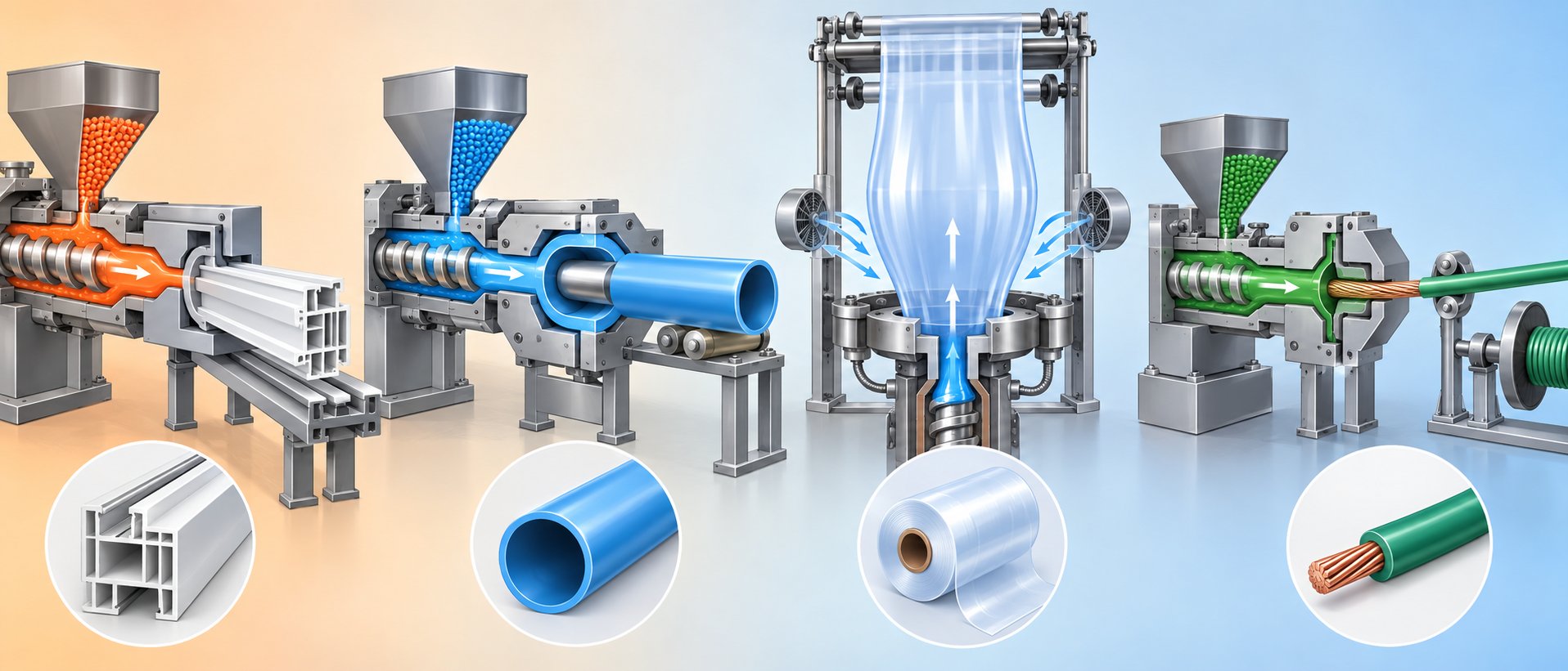
Specifications define a machine's capabilities, but the extrusion process you choose defines what those capabilities actually produce. A single extruder platform can manufacture products as different as garden hose, food-wrap film, and structural window profiles - simply by changing the die, adjusting the downstream equipment, and dialing in a new thermal profile. The real skill lies in knowing which process pairs with which machine configuration and material. Let's walk through the major categories.
Profile, Pipe, and Sheet Extrusion Processes
Profile extrusion pushes molten polymer through a die whose opening mirrors the cross-section of the finished part - think window frames, weatherstripping, edge trim, and decorative moldings. Because these shapes often include hollow chambers and thin walls, die design and downstream calibration are critical. Vacuum sizing sleeves hold the still-soft extrudate to its exact dimensions while cooling water solidifies the shape. PVC dominates this space due to its rigidity, weather resistance, and flame retardance.
Pipe extrusion is one of the highest-volume applications of the thermoplastic extrusion process. An annular die creates a hollow tube that passes through a vacuum calibration tank and then a series of cooling baths before a haul-off unit pulls it at a controlled speed to maintain wall thickness. The choice of extruder type here depends heavily on the polymer. The PVC extrusion process typically relies on counter-rotating twin-screw (double-screw) extruders fed with dry-blend powder, because PVC exhibits more wall slip and requires lower shear to avoid degradation. Polyolefin pipes - HDPE and PP - are processed in granular form on single-screw machines that can deliver the roughly three times greater specific energy input these materials need. A modern plastic pipe extrusion machine for either material family shares the same downstream concept, but the extruder at its heart differs fundamentally.
Sheet and flat-film extrusion uses a wide, flat die - sometimes called a coat-hanger die because of its internal manifold shape - to spread the melt into a thin, uniform curtain. The extrudate is immediately drawn onto polished chill rolls or passed through a water quench, depending on thickness and material. Thin flat films serve packaging markets, while thicker sheets feed thermoforming lines for cups, trays, and automotive interior panels. PE, PP, PET, and ABS are all common feedstocks here.
Blown Film, Wire Coating, and Co-Extrusion
Blown film extrusion takes a different approach to producing thin film. Instead of a flat die, the melt exits through an annular die and is inflated into a bubble by internal air pressure. As the bubble rises through a cooling ring, it solidifies into a tube of film that is then collapsed by nip rolls, slit if needed, and wound onto reels. This polymer extrusion process is the backbone of flexible packaging - grocery bags, shrink wrap, agricultural mulch film, and barrier pouches. Blow-up ratio and frost-line height give operators precise control over film thickness and mechanical properties.
Wire and cable coating uses a crosshead die mounted at a right angle to the extruder barrel. The bare conductor passes through the center of the die while molten insulation is applied concentrically around it. Speed synchronization between the wire payoff, the extruder output, and the downstream capstan is essential - any mismatch creates thin spots or bare patches. PVC, PE, and cross-linked polyethylene (XLPE) are the dominant materials, each chosen for its specific dielectric and thermal performance.
Co-extrusion combines melt streams from two or more extruders into a single die, producing multi-layer products where each layer contributes a different property. Imagine a food-packaging film with a moisture barrier on one side, a heat-seal layer on the other, and a structural core in between - all formed in one pass. Co-extrusion applies equally to blown film, flat film, sheet, pipe, and profile, making it one of the most versatile techniques in extrusion in polymers.
One more process deserves mention: reactive extrusion. Here, the extruder doubles as a continuous chemical reactor. Monomers or polymers and reagents are fed together, and polymerization, grafting, or crosslinking reactions occur inside the barrel as the material is conveyed and mixed. Reactive extrusion is generally carried out on co-rotating twin-screw extruders due to their high mixing capacity and modular screw design. Applications range from synthesizing thermoplastic polyurethanes to functionalizing polyolefins with maleic anhydride and even chemical recycling of PET through glycolysis. Because reaction kinetics must fit the extruder's residence time - typically one to twenty minutes - long L/D ratios of 44:1 up to 90:1 are common.
Material-to-Machine Reference
Picking the right process is only half the decision. You also need to match the polymer to the correct machine architecture. The table below maps the most common materials to their recommended extruder type, approximate L/D range considerations, and typical product applications.
| Material | Recommended Extruder Type | L/D Range Considerations | Typical Product Applications |
|---|---|---|---|
| PE (HDPE, LDPE, LLDPE) | Single-screw (grooved feed preferred for HDPE) | 24:1 to 30:1 | Pipe, blown film, wire coating, sheet |
| PP | Single-screw | 24:1 to 30:1 | Flat film, sheet, fibers, profiles |
| PVC (rigid) | Counter-rotating twin-screw (dry blend feed) | 20:1 to 24:1 (shorter to limit residence time) | Pipe, window profiles, siding, sheet |
| ABS | Single-screw or co-rotating twin-screw for blends | 24:1 to 30:1 | Sheet for thermoforming, profiles, co-extruded layers |
| Rubber (EPDM, silicone) | Cold-feed single-screw or ram extruder for ultra-high viscosity | 12:1 to 20:1 (lower shear to prevent scorching) | Seals, gaskets, tubing, weatherstrips |
| Filled / recycled compounds | Co-rotating twin-screw | 32:1 to 48:1+ (extended for compounding and devolatilization) | Compounded pellets, masterbatch, recycled blends |
| Reactive systems (TPU, grafted PO) | Co-rotating twin-screw | 44:1 to 90:1 (long barrels for residence time) | Specialty polymers, functionalized resins, chemical recycling |
Notice that compounding and reactive extrusion for filled or recycled materials almost always require a twin-screw configuration. The intensive mixing, modular screw design, and ability to add side-stream feeds at multiple barrel positions make the co-rotating twin-screw the default for anything beyond straightforward melt pumping.
Matching material properties to machine configuration is the foundation of successful extrusion. The best die design and the most advanced controls cannot compensate for running a polymer on an extruder type that does not suit its melting behavior, thermal sensitivity, or mixing requirements.
Of course, the extruder and its die are only the centerpiece of a much larger production system. What happens before material enters the hopper and after it exits the die can be just as decisive for final product quality - a reality that becomes clear once you look at the full extrusion line from end to end.
The Complete Extrusion Line Beyond the Extruder
An extruder machine does not work in isolation. Strip away everything upstream and downstream, and all you have is a pump pushing molten polymer into the open air - no controlled shape, no consistent dimensions, no finished product. The reality is that a production-ready extruder line includes dozens of ancillary components, each influencing product quality as directly as the screw and barrel themselves. Understanding this complete ecosystem is what separates someone who can run a machine from someone who can run a process.
Upstream Material Handling - Drying, Dosing, and Feeding
Everything that happens before pellets reach the feed throat shapes the melt quality downstream. Think of it this way: the extruder can only homogenize what it receives. Feed it inconsistent material, and no amount of barrel-temperature tweaking will rescue the output.
Drying is the first critical step for any hygroscopic resin - PET, polycarbonate, ABS, nylon, and others that absorb atmospheric moisture. Internal moisture trapped in pellets flash-vaporizes during melting, creating voids, splay marks, discoloration, and structural weakness in the finished part. Even for non-hygroscopic polymers, consistent drying homogenizes incoming material temperature, eliminating the seasonal swings that occur when resin sits in a cold warehouse in January or a hot silo in August. Centralized desiccant dryers, machine-side units, and mobile drying carts all serve this purpose - the right choice depends on throughput volume and the number of materials in rotation.
Dosing and blending ensure the extruder receives the correct recipe of virgin resin, recycled pellets, colorant masterbatch, and performance additives on every revolution of the screw. Two feeder philosophies dominate industrial extrusion machinery:
- Volumetric feeders dispense material based on volume, estimating mass from assumed density. They are simpler, more affordable, and effective when material characteristics stay relatively consistent and minor weight variations are acceptable.
- Gravimetric feeders measure the actual weight of material in real time, dynamically adjusting dispensing rates to compensate for density changes, pellet-size variation, or hopper-level fluctuation. The precision they deliver is essential in applications where tight additive ratios are non-negotiable - medical-grade tubing, multi-layer barrier films, or color-critical consumer products.
Choosing the wrong feeder type is a common and costly mistake. A volumetric system on a line requiring one-percent color accuracy will produce visible batch-to-batch variation. A gravimetric system on a simple mono-material pipe line may be overkill that adds unnecessary complexity. Match the feeder to the tolerance your product demands.
Downstream Equipment - Cooling, Cutting, and Finishing
Hot extrudate leaving the die is soft, dimensionally unstable, and useless as a product. Downstream extruding equipment transforms it into something you can actually ship.
Calibration and sizing come first. Vacuum sizing sleeves or calibration plates hold the still-pliable extrudate to its target dimensions while it begins to cool. For hollow profiles and pipes, internal vacuum prevents collapse, while external vacuum pulls the outer surface against the sizing tool. This is where final geometry is locked in - and where dimensional tolerances are won or lost.
Cooling removes enough heat for the product to solidify and hold its shape permanently. Methods vary by application: immersion tanks submerge the product in temperature-controlled water, spray tanks apply a fine mist for larger extrusions like decking or heavy-wall pipe, and air cooling serves applications where water contact is undesirable. Temperature control units (TCUs) supply tempered water at a constant temperature, ensuring a consistent rate of heat transfer regardless of ambient conditions or how long the line has been running.
Haul-off (puller) units grip the cooled product with belts or cleated tracks and draw it through the entire downstream train at a precisely controlled speed. Puller speed, regulated by the master extrusion control, is one of the most sensitive variables in the process - minute adjustments directly affect wall thickness, outer diameter, and weight per meter. Too fast, and the product stretches thin. Too slow, and it thickens beyond tolerance.
Cutting and collection finish the job. Rotary cutters, flying saws, or guillotine blades sever the continuous extrudate into specified lengths, synchronized to line speed so cuts happen without stopping or marking the product. Flexible products like tubing or film bypass the cutter and wind directly onto reels using automatic coilers. Printers or embossing units can mark product identification, lot numbers, or meter markings upstream of the cutter.
Here is the full sequence of an extruder line from raw material intake to finished product, laid out as a single production flow:
- Raw material receiving and storage (silos, bins, gaylords)
- Conveying to processing area (vacuum conveying systems)
- Drying or dehumidification (desiccant dryers, hot-air dryers)
- Dosing and blending (gravimetric or volumetric feeders, blenders)
- Extrusion (screw melting, mixing, and pressurization through the barrel)
- Die shaping (melt formed into target cross-section)
- Calibration and vacuum sizing (dimensional stabilization)
- Cooling (immersion tanks, spray tanks, or air cooling with TCU-controlled water)
- In-line measurement (laser or ultrasonic gauging for real-time dimensional feedback)
- Haul-off / puller (speed-controlled drawing through downstream equipment)
- Printing or marking (product identification, lot codes, length marks)
- Cutting to length or winding onto reels
- Take-off, stacking, or packaging for shipment
Every station in that sequence interacts with the ones before and after it. A dryer malfunction sends moisture into the barrel, causing splay in the extrudate. A TCU drifting two degrees changes the cooling rate, shifting product dimensions enough to trigger rejects. A puller with a worn belt slips intermittently, producing periodic wall-thickness variation that looks like an extruder surging problem but has nothing to do with the screw.
This is the insight many operators learn the hard way: extrusion equipment performance issues frequently originate from mismatched or poorly maintained ancillary components rather than the extruder itself. Diagnosing the real source demands looking at the entire line as a connected system - a perspective that becomes indispensable when production problems appear and the pressure to fix them fast is on.
Troubleshooting Common Extruder Machine Problems
Something has gone wrong on the line. Output weight is drifting, the melt looks rough, or die pressure is climbing faster than it should. You know the entire extruder line is interconnected - but where do you start? The answer is almost always the same: identify the symptom precisely, trace it upstream to the most likely cause, then act on the root issue instead of chasing secondary effects. Below is a practical, category-by-category guide to the problems operators encounter most often on plastic extruder machine production lines.
Output Instability and Throughput Fluctuation
Surging - the rhythmic rise and fall of output rate while all set points remain constant - is one of the most frustrating issues on any plastics extruder. It drives up scrap, forces conservative speed targets, and can mask other defects. The most common root cause? Improper temperatures in the solids-conveying section. Research by Dow's Mark Spalding demonstrates that forwarding forces at the barrel wall depend heavily on surface temperature. When the feed casing overheats - often because cooling-water channels have occluded with mineral deposits - or the screw itself runs too hot due to inadequate internal cooling, solids conveying becomes erratic. The screw alternates between grabbing and slipping against the pellet bed, and the extruder system responds with visible oscillations in motor current, screw speed, and discharge pressure.
Feed-throat bridging creates a different pattern. Instead of a smooth cycle, you will see sudden output drops followed by recovery as material collapses past the blockage. Causes include fines accumulation, moisture-swollen pellets, or a feed-throat temperature that is too high for the resin's softening point. Inconsistent blending - particularly when regrind with variable bulk density enters the mix - can produce a similar symptom by changing the mass of material entering the screw with every hopper refill.
Worn screw flights deserve special attention here. As the clearance between flight tips and barrel wall increases, leakage flow back over the flights rises. The screw's pumping efficiency drops, and output becomes increasingly sensitive to small changes in back-pressure or feed consistency. What used to be a stable process starts surging under conditions that worked fine six months earlier.
Melt Quality, Pressure, and Overheating Problems
Unmelted particles ("unmelts") and gels in the extrudate usually point to inadequate residence time, incorrect temperature profiling, or a compression ratio that does not suit the resin. Unmelts are literal fragments of solid polymer that survived the compression and metering zones. Gels, by contrast, are crosslinked or degraded polymer clusters - often caused by material that has been sitting in stagnant zones of a worn barrel or poorly designed die for too long.
Die-pressure fluctuation ties directly to upstream instabilities in feeding, melting, or filtration. A slowly rising head pressure typically signals screen-pack loading - contamination gradually blocking the mesh and increasing resistance. A cyclic pattern that matches feeder-refill intervals points back to material handling. And when pressure and motor load rise together without any change in downstream tooling, you are likely dealing with a viscosity shift from a colder melt, a resin-lot change, or excessive screw and barrel wear that has reduced the machine's ability to generate stable pressure.
Barrel overheating is a subtler problem. When the extruder generates more shear heat than the cooling system can extract, actual melt temperature climbs above set points. Shear-sensitive materials like rigid PVC and certain styrenics begin to degrade, producing discoloration, odor, and brittleness. Excessive screw speed is the usual culprit, but worn barrels contribute too - increased clearance forces the screw to work harder to maintain output, generating more frictional heat in the process.
Blockage and Mechanical Wear Issues
Die blockage and carbon buildup are symptoms of polymer degradation that has been allowed to accumulate over time. Dead spots in the flow channel - sharp corners, poorly polished surfaces, or gaps between adapter sections - trap material that eventually chars. These carbon particles periodically break free and lodge in the die lips, creating streaks or blocking flow paths entirely. Regular purging and streamlined die designs minimize the risk, but once buildup is established, manual disassembly and cleaning become unavoidable.
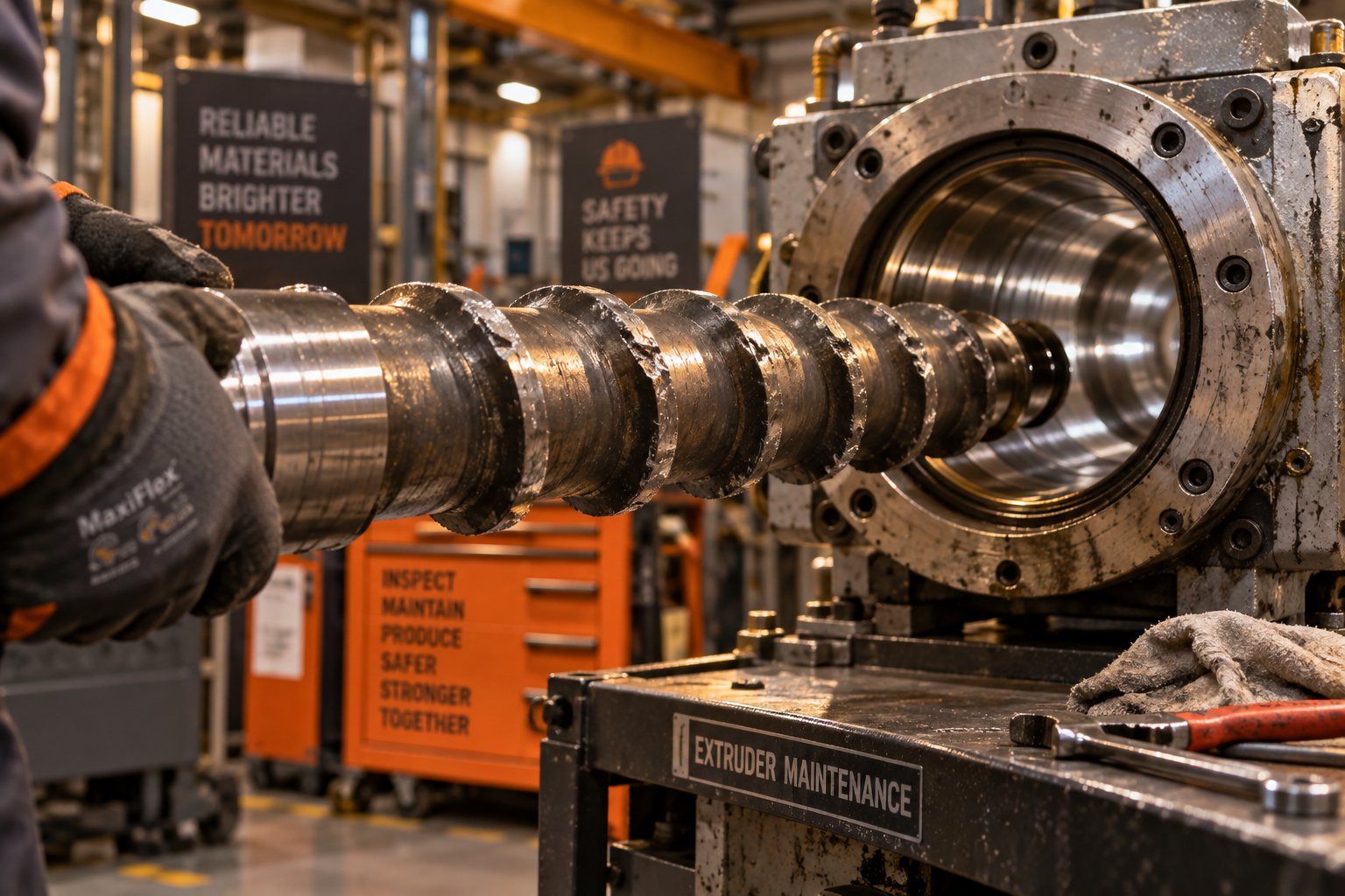
Screw and barrel wear follows predictable patterns. The highest wear occurs at the end of the compression zone and the beginning of the metering zone, where melt pressure peaks and abrasive fillers (glass fiber, calcium carbonate, talc) grind hardest against metal surfaces. Bimetallic barrel liners and hardened screw coatings extend service life, but all wear parts are consumables. The critical point is recognizing when wear has crossed the threshold from acceptable to performance-degrading - and that threshold arrives earlier than most plants expect.
The table below organizes the most common symptoms into a problem-cause-solution format you can reference directly on the production floor.
| Symptom | Likely Cause(s) | Recommended Action |
|---|---|---|
| Output surging (cyclic weight/rate variation) | Hot feed casing or hot screw in solids-conveying zone; occluded cooling channels; worn screw flights reducing pumping efficiency | Check feed-casing temperature (should be warm, not hot); verify screw-cooling water flow and temperature; inspect flight-tip clearance and replace worn screw or barrel as needed |
| Feed-throat bridging or starving | Excessive feed-zone temperature; fines or dust accumulation; moisture-swollen pellets; inconsistent regrind bulk density | Lower feed-throat cooling-water temperature; clean hopper and throat; screen or dry material; stabilize regrind particle size |
| Unmelts in extrudate | Insufficient residence time; compression ratio mismatched to resin; low barrel temperatures in compression zone; worn screw reducing compaction | Increase compression-zone temperature; verify screw design suits the polymer; check screw and barrel wear; consider barrier-screw upgrade |
| Gels or black specks | Degraded polymer from dead spots in barrel, die, or adapter; excessive residence time; infrequent purging | Purge regularly between runs; inspect and polish flow channels; eliminate dead spots in adapter and die assembly; reduce unnecessary residence time |
| Gradually rising die pressure | Screen-pack loading from contamination or degraded material; increasing die restriction from carbon deposits | Monitor differential pressure across screen pack; change screens on a scheduled interval; clean die and adapter; review regrind contamination levels |
| Cyclic pressure fluctuation | Feeder-refill pulses; solids-conveying instability; control-loop hunting between extruder and gear pump | Trend pressure against feeder events; stabilize feed system; review PID tuning; ensure gravimetric blender is properly calibrated |
| Barrel overheating / melt degradation | Excessive screw speed for the material; worn barrel increasing shear demand; failed cooling fans or blocked air channels | Reduce RPM; verify cooling-system function; check barrel bore for wear; match screw speed to material's shear sensitivity |
| Die blockage or streaks | Carbon buildup in dead zones; degraded material lodging in die lips; poor flow-channel design | Disassemble and clean die; polish flow surfaces; redesign adapter to eliminate stagnant zones; implement routine purging schedule |
| Declining output over weeks/months with no set-point changes | Progressive screw-flight and barrel-bore wear increasing clearance and leakage flow | Measure screw OD and barrel ID at multiple points; compare to manufacturer tolerances; source precision-engineered replacement components from a specialist supplier such as NANHAIYA |
A pattern emerges across nearly every row in that table: screw and barrel condition is the common thread linking multiple simultaneous symptoms. Worn components reduce compression, shift the melting zone downstream, increase melt-temperature variation, and erode output consistency - all at once. When a plastic extruding machine starts exhibiting two or three of these issues together, experienced operators know the screw and barrel are usually the first place to look.
Restoring performance often comes down to sourcing wear parts that meet tight dimensional tolerances and metallurgical specifications. Specialized screw barrel suppliers like NANHAIYA support extrusion plants and recycling operations with replacement components engineered for this purpose - helping teams move from diagnosis to resolution without extended downtime. Whether you are replacing a single worn screw tip or upgrading an entire barrel assembly, having a reliable component partner shortens the path from identifying wear to running stable production again.
Diagnosing and fixing problems is essential, but it is ultimately reactive. The smarter long-term strategy is choosing the right extruder machines in the first place - a decision that depends on far more than sticker price.
How to Select the Right Extruder Machine
Fixing a poorly matched extruder is expensive. Choosing the right one from the start is not. Yet many buyers jump straight to browsing extrusion equipment for sale or comparing extruder machine price lists before they have answered the questions that actually determine which machine fits. A structured selection framework - working backward from your product requirements - prevents that costly shortcut.
Matching Machine Type and Size to Your Application
Start with what you need to produce, not what is available to buy. Three variables do the heaviest filtering work:
Material type. Identify the polymer or compound you will process most frequently. Pre-compounded PE or PP pellets running through a single product die? A single-screw machine almost certainly delivers the best value. Recycled post-consumer flake with variable contamination, or a filled compound requiring intensive mixing? A co-rotating twin-screw is likely non-negotiable. Rigid PVC dry blend? Counter-rotating or conical twin-screw designs protect the resin from thermal degradation. As the NANHAIYA technical comparison notes, applying these three decision factors in sequence eliminates at least two or three configurations before any supplier walks through your door.
Product geometry and output rate. A narrow medical tube demands a small-diameter screw with precise metering-zone control. A high-volume drainage pipe line needs a large-bore barrel capable of hundreds of kilograms per hour. Work backward from your target throughput to determine screw diameter - remember, output scales roughly with the square of that dimension - and then select an L/D ratio that gives your resin adequate residence time without risking degradation.
Formulation complexity. If your roadmap includes adding glass fiber, switching between multiple color masterbatches weekly, or processing post-industrial regrind alongside virgin resin, prioritize modular screw designs and machines that support side-stream feeding. Plants that begin with simple extrusion but anticipate growing complexity often find a twin-screw platform protects their capital investment against future product-line shifts.
Evaluating Manufacturers and Total Cost of Ownership
Comparing extruder manufacturers on purchase price alone is like choosing a car based on the sticker and ignoring fuel economy, tire replacement, and repair costs for the next decade. The real financial picture emerges only when you evaluate total cost of ownership.
Total cost of ownership - including wear-part replacement, energy consumption, unplanned downtime, and operator training - often exceeds the initial capital investment over the machine's productive life. Buyers who select equipment based on the lowest upfront price frequently face regret within two to three years as ongoing costs erode the initial savings.
When you evaluate extrusion machine suppliers or search for an extruder for sale, look beyond the machine frame. Consider these factors as a due-diligence checklist:
- Energy consumption per kilogram of output - request specific energy data (kWh/kg) for your target material and throughput
- Screw and barrel replacement cost and lead time - these are the parts you will replace most often; sourcing reliable support from specialists like NANHAIYA ensures compatibility, consistent metallurgy, and shorter turnaround when wear parts come due
- Spare-parts availability - confirm whether critical components (gearbox seals, heater bands, thermocouples, drive belts) are stocked or made to order
- Control-system sophistication - recipe storage, data logging, and remote diagnostics reduce operator dependency and speed troubleshooting
- After-sales technical support - on-site commissioning, operator training, and responsive engineering assistance during production problems
- Certifications and compliance - CE marking, ISO standards, and documentation packages required for your market
- Reference installations - ask for case studies or contact details of existing customers running similar materials and products
One step most buyers skip - but shouldn't - is evaluating screw barrel component suppliers before finalizing the machine purchase. Knowing what replacement options exist in terms of metallurgy, dimensional precision, and delivery timelines lets you factor realistic ongoing costs into your decision. A machine with a competitive extruder machine for sale price can become the most expensive option on your floor if affordable, high-quality wear parts are difficult to source two years later. NANHAIYA's product catalog gives engineers a practical starting point for comparing screw barrel options across single-screw, parallel twin-screw, and conical twin-screw configurations - making it straightforward to verify component availability and compatibility regardless of which extruder manufacturer builds the machine itself.
Selecting the right machine and locking in a reliable supply chain for its consumable components positions your line for years of stable production. But even the best-chosen equipment operates in a market that keeps evolving - and the technologies reshaping extruder design right now are worth understanding before you finalize any capital commitment.
Emerging Trends Shaping Extruder Technology
The extruder you install today will run for a decade or more. That makes it worth asking: what is an extrusion machine going to look like - and be expected to do - five years from now? Equipment builders have given a clear answer through a wave of recent product launches, and the direction is unmistakable. Extrusion machines are getting more energy-efficient, digitally intelligent, and capable of handling feedstocks that would have been considered unprocessable a generation ago.
Energy Efficiency and Sustainable Extrusion
Energy is one of the largest ongoing costs in any extrusion operation, and every watt saved per kilogram of output drops straight to the bottom line. Modern high-performance extrusion machine designs attack this problem from multiple angles.
Servo-driven motors and optimized gearboxes have largely replaced older AC vector drives, delivering higher torque density with less electrical loss. The efficiency gains are not marginal - processors switching from legacy hydraulic or standard induction motors to servo-electric platforms routinely report double-digit energy reductions for the same throughput.
Screw design innovation is equally impactful. Balanced screw geometries that maximize the conversion of mechanical energy into melt preparation - rather than dumping excess shear heat that must then be removed by cooling - reduce specific energy consumption significantly. In PVC pipe extrusion, for example, optimized twin-screw systems achieve specific energy consumption around 100 Wh/kg at the extruder, with a theoretical minimum near 80 Wh/kg. Air cooling and closed internal screw cooling replace fluid-based systems in these designs, cutting both maintenance requirements and parasitic energy losses.
Recycled and bio-based feedstocks add a new dimension to the efficiency conversation. Post-consumer recycled plastics arrive with variable melt-flow characteristics, moisture content, and contamination levels that legacy equipment struggles to handle cleanly. Newer extrusion machinery addresses this head-on. Erema's Volex water-stripping degassing process, for instance, doses water into the melt to multiply exposed surface area roughly 1,000-fold, boosting VOC removal by up to 40 percent and enabling higher recycled-content ratios in finished products. Meanwhile, Battenfeld-Cincinnati's Dual Vent Technology uses two independent degassing zones to pull moisture and volatiles from untreated regrind - potentially eliminating the need for pre-drying entirely. These innovations make automatic extrusion of contaminated or mixed-stream recycled plastics commercially viable at scale.
Smart Controls and Industry 4.0 Integration
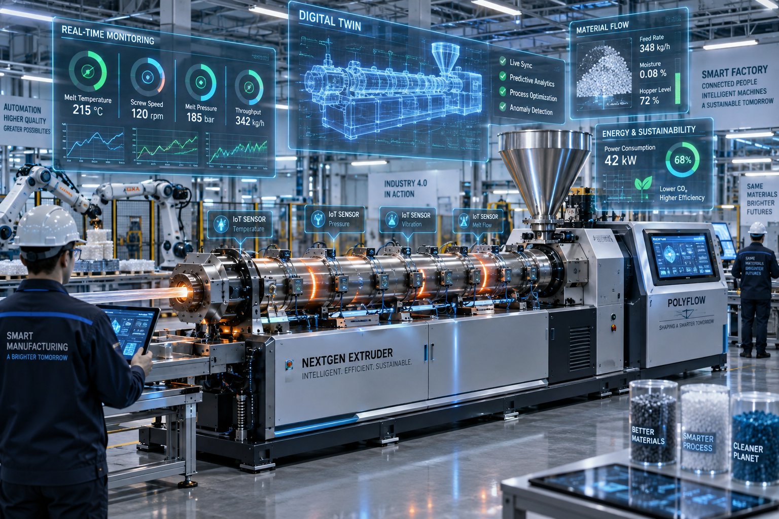
What separates a modern extruder from its predecessor is not just better hardware - it is the intelligence layered on top. Automated extrusion machines increasingly rely on interconnected digital systems that monitor, predict, and optimize in ways human operators alone cannot match.
IoT sensor networks embedded throughout the barrel, die, and downstream equipment track temperature, pressure, motor load, and vibration in real time, feeding continuous data streams to centralized control platforms. Instead of an operator checking a gauge every thirty minutes, the system flags deviations the instant they begin - often before they produce a visible defect.
Predictive maintenance turns that sensor data into actionable foresight. Coperion's Lifecycle Manager, launched alongside its latest twin-screw extruders, uses operating hours and performance data to forecast service needs and log maintenance history, while condition-monitoring modules watch for vibration anomalies in the motor, gearbox, and process section. GL Control's Citris system takes a different approach, using optical scanning to map extruder barrel wear in three dimensions from up to 50 million data points - giving plant teams a data-backed basis for replacement decisions rather than guesswork.
AI-assisted parameter optimization closes the loop. Rather than relying on an experienced operator to adjust temperatures, speeds, and pressures based on intuition, AI algorithms analyze historical and real-time data to recommend - or autonomously apply - the settings that minimize scrap, energy use, and cycle time. Milacron's MosaicX control platform, for example, monitors more than 50 parameters simultaneously with graphical trending, making production data accessible across skill levels through role-based dashboards.
Taken together, these technologies reduce waste, improve consistency, and lower the operator-skill threshold needed to maintain quality. They do not eliminate the need for human expertise - experienced engineers remain essential for troubleshooting, material-selection decisions, and process development - but they compress the feedback loop from hours or shifts down to seconds.
Here are the key technology trends reshaping the next generation of extrusion machinery:
- High-efficiency servo motors and optimized drive trains cutting specific energy consumption
- Advanced screw designs that reduce reliance on external heating and intensive cooling
- Dual-vent and water-stripping degassing systems enabling processing of contaminated recycled feedstocks
- IoT-enabled real-time monitoring of temperature, pressure, vibration, and throughput across the full line
- Predictive maintenance platforms that forecast wear-part replacement and schedule service proactively
- AI-driven closed-loop process control for autonomous parameter optimization
- Digital twins that simulate process changes virtually before committing to physical trials
- Larger-scale extrusion platforms - including 360 mm single-screw and 400 mm twin-screw machines - pushing throughput boundaries for hot melt extruder machine applications and beyond
- Modular, retrofit-friendly control systems that bring Industry 4.0 capabilities to existing installed equipment
Yet for all this sophistication, a fundamental truth holds: the most advanced sensor network cannot compensate for a mismatched screw design, and the smartest AI cannot fix a worn barrel. Understanding extruder fundamentals - from screw geometry and compression ratios to material behavior and zone-by-zone thermal management - remains the essential foundation regardless of how automated the line becomes. The technologies above amplify good engineering; they do not replace it.
That is the throughline connecting every section of this guide. Whether you arrived here asking a basic question about what an extruder does or you are evaluating your next capital investment in a high-performance extrusion machine, the same principles apply: match the machine to the material, understand the process from pellet to finished product, maintain your wear components before they degrade your output, and leverage the digital tools now available to run tighter, leaner, and smarter. Master those fundamentals, and the technology - no matter how fast it evolves - works for you rather than against you.
Frequently Asked Questions About Extruder Machines
1. What is an extruder machine and how does it work?
An extruder machine uses one or more rotating screws inside a heated barrel to melt, mix, and pressurize raw material - typically plastic pellets or powder - then forces the molten material through a shaped die to create continuous products like pipes, films, and profiles. The process moves through three barrel zones: a feed zone that conveys solid pellets, a compression zone that compacts and melts them through friction and external heat, and a metering zone that delivers a uniform melt to the die at stable pressure. Screw geometry, barrel temperature settings, and die design all work together to control output quality and throughput rate.
2. What is the difference between a single-screw and twin-screw extruder?
Single-screw extruders use one rotating screw and excel at efficiently pumping pre-compounded, well-characterized polymers into final shapes like pipes, sheets, and profiles. They cost less and are simpler to maintain. Twin-screw extruders use two intermeshing screws and deliver superior mixing and compounding capability, handling filled, recycled, reactive, and multi-component formulations that a single screw cannot homogenize adequately. Co-rotating twin-screws are preferred for compounding and reactive extrusion, while counter-rotating twin-screws handle thermally sensitive materials like rigid PVC. Many production facilities use both types: a twin-screw compounder prepares the material, and a single-screw line shapes the final product.
3. What are the most important specifications to consider when buying an extruder?
最关键的规格包括螺杆直径(决定产量规模,因为直径增加50%时产量大致翻倍)、长径比(影响停留时间和熔体均匀性,通常为20:1至30:1)、压缩比(必须与聚合物的堆积密度相匹配)、电机扭矩和功率(决定最大输入功率)、螺杆转速范围以及独立加热和冷却区的数量。除了规格之外,买家还应评估总拥有成本,包括每公斤产量的能耗、螺杆和料筒的更换成本和供应商(如南海亚)的交货周期、备件供应情况、控制系统功能以及售后技术支持。
4. 挤出机输出出现波动的原因是什么?如何解决这个问题?
产量波动——即在恒定设定值下输送量出现有节奏的上升和下降——最常见的原因是固体输送段的温度不合适。当进料壳体因冷却水通道堵塞而过热,或螺旋桨因内部冷却不足而过热时,固体输送就会变得不稳定。磨损的螺旋桨叶片也会加剧漏料,导致叶片尖端回流增加,从而降低泵送效率。为了解决产量波动问题,应检查进料壳体的温度是否温热(而非过热),确认螺旋桨冷却水流量,并测量叶片尖端间隙是否在制造商规定的公差范围内。如果间隙超出可接受的范围,则需要从专业供应商处采购精密设计的替换螺旋桨和筒体,以恢复稳定的产量。
5. 一条完整的挤出生产线需要哪些下游设备?
一条完整的生产级挤出生产线远不止挤出机本身。在上游,需要用于干燥吸湿性树脂的物料干燥系统,以及用于精确计量和混合的重力式或容积式喂料器。在下游,该生产线还包括用于锁定产品尺寸的真空校准或定型装置、配备温控水的冷却槽或喷淋系统、以精确控制的速度牵引产品的牵引装置、用于尺寸验证的在线测量装置、用于产品标识的打印机或标记器,以及用于收集成品的切割系统或卷取机。性能问题通常源于不匹配或维护不当的辅助设备,而非挤出机本身。
Written by
Nanhaiya Technical Team
Zhoushan Nanhaiya Plastic Machinery Co., Ltd.
The Nanhaiya technical team supports screw and barrel manufacturing projects through application review, technical communication, custom manufacturing coordination, and production and quality control.
Discuss Your Application
Related Articles
More insights on screw barrel technology and plastics processing.

PE Pipe Making Machine Decoded: From Raw Resin to Flawless Pipe
Oct 4, 2026
Learn how a PE pipe making machine works, from resin to finished pipe. Covers components, material grades, automation, troubleshooting, and buyer selection tips.
Read Article
PVC Profile Making Machine Decoded: From Raw Resin To Profit
Oct 3, 2026
Learn how a PVC profile making machine works — extrusion process steps, key technical parameters, die design, calibration methods, maintenance, and total cost of ownership.
Read Article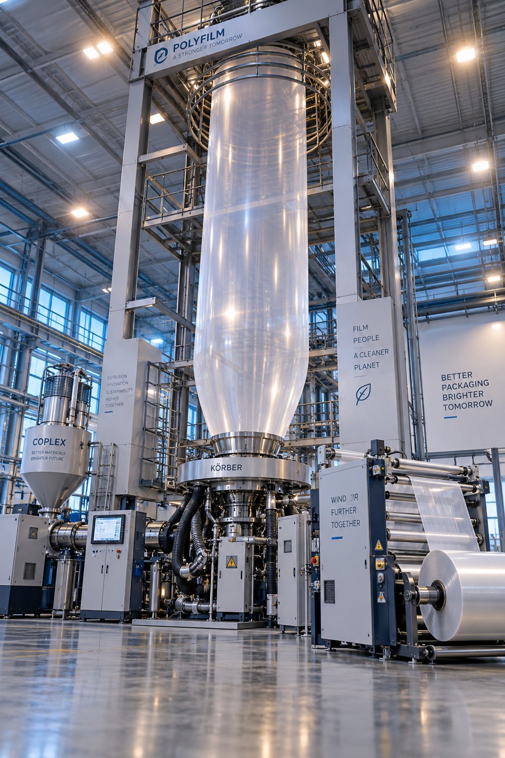
Blown Film Extrusion Machine Decoded: From Resin to Finished Roll
Sep 28, 2026
Learn how a blown film extrusion machine works — components, process parameters, BUR calculations, multi-layer setups, resin compatibility, and maintenance tips.
Read ArticleLooking for something else?
Search by material, symptom or product and jump straight to the relevant page.
These are navigation suggestions based on keyword matching — not a quotation, not a delivery commitment, and not a substitute for engineering review. Final specification is confirmed by our engineers against your drawings and processed material.
Need help with screw barrel selection?
Share your machine model, processed material and application. Our team can help with pricing and technical support.