


什么是PE管材制造机以及它为何如此重要
提到“PE管材制造机”,你可能会想到一台单独的设备冲压成型塑料管材。但实际情况远比这有趣得多,也复杂得多。它指的是一条完整的集成生产线,由一系列精确同步的机器组成,这些机器协同工作,通过连续挤出,将聚乙烯树脂原料颗粒转化为成品、可直接安装的管材。
PE管材生产线是一套完整的生产线,而非单一设备,它通过连续挤出将聚乙烯(PE)原料树脂转化为成品管材。该生产线通常包括单螺杆挤出机、环形模头、真空定径槽、喷淋冷却槽、牵引装置、切割工位和堆垛机,所有部件协同工作,以生产尺寸精确、质量稳定的管材。
什么是PE管材制造机
不妨这样理解:挤出机是整个系统的核心,但光有核心并不足以构成完整的躯体。一条聚乙烯(PE)管材生产线集成了物料输送和计量设备、熔化并挤出聚合物的挤出机、将熔融塑料成型为空心管的模头、将管材精确固化至所需尺寸的真空校准和冷却槽、以可控速度牵引管材的牵引装置,以及将管材切割成所需长度的切割机。每个组件都与其他组件相互依存,才能最终生产出完美的产品。
关于术语的简要说明:您经常会看到“PE”和“HDPE”在本文语境中互换使用。PE代表聚乙烯,它是热塑性聚合物的一个大类。HDPE(高密度聚乙烯)是压力管道应用中最常用的等级,但这些生产线也能加工其他类型的聚乙烯,例如MDPE、LDPE和PE-RT。这些机器本身功能强大,只需调整温度曲线和螺杆转速,即可处理多种等级的聚乙烯。
这些生产线涵盖了令人印象深刻的管径范围,从用于滴灌和电缆保护的16毫米小直径管,到用于市政供水干管和工业应用的1600毫米以上大直径管,应有尽有。不同的管径范围需要不同的挤出机尺寸、模头配置和下游设备,但其基本原理——熔融聚乙烯通过环形模头连续挤出——保持不变。
为什么PE管材生产线对现代基础设施至关重要
Why does all of this matter? Because polyethylene pipes have become the backbone of modern infrastructure across the globe. Their combination of durability, flexibility, corrosion resistance, and an expected service life of 50 to 100 years makes them the preferred choice over traditional materials like iron, concrete, and copper in a growing number of applications.
Consider the range of industries that rely on PE pipes every day:
- Municipal water supply - PE pipes carry potable water across distribution networks, resisting corrosion and biological growth that plague metal alternatives.
- Natural gas distribution - Heat-fused PE joints eliminate leak points, making polyethylene a safe, reliable choice for gas networks.
- Mining and slurry transport - The abrasion resistance and flexibility of PE pipes make them ideal for harsh mining environments where rigid pipes crack under stress.
- Telecommunications and cable ducting - HDPE conduit protects fiber optic cables, power lines, and communication infrastructure underground.
- Agricultural irrigation - Lightweight PE pipes are easy to deploy across fields and withstand soil movement without joint failure.
The global HDPE pipes market is projected to grow at a 5.1% CAGR through 2032, driven by infrastructure expansion, water system upgrades, and the ongoing shift from legacy pipe materials to polyethylene. That growth translates directly into rising demand for the polyethylene pipe manufacturing equipment that makes production possible.
With so many applications and configurations to consider, the question quickly shifts from "what is this equipment?" to "what type of production line do I actually need?" The answer depends heavily on whether you're producing solid-wall pressure pipes or structured-wall drainage pipes - two fundamentally different line configurations that share the same name.
Solid-Wall vs Structured-Wall PE Pipe Lines Explained
Here's something that trips up many first-time buyers: the term "PE pipe making machine" doesn't describe a single type of production line. It actually covers two fundamentally different equipment configurations - solid-wall extrusion lines and structured-wall (corrugated or profiled) pipe lines. They use different die designs, different forming methods, and produce pipes for entirely different applications. Choosing the wrong configuration means investing in equipment that simply cannot make the product you need.
Understanding this distinction before you start evaluating suppliers will save you time, money, and a lot of frustration.
Solid-Wall PE Pipe Extrusion Lines
Solid-wall lines are what most people picture when they think of polyethylene pipe production. These systems produce smooth, uniform-wall pipes with consistent cross-sections - the kind you'll find carrying pressurized water through municipal networks or distributing natural gas beneath city streets.
The setup follows a straightforward linear configuration: a single-screw extruder melts PE resin and forces it through an annular die head, which shapes the melt into a hollow tube. That tube immediately enters a vacuum sizing tank, where calibration sleeves and vacuum pressure lock in the pipe's outer diameter and wall thickness. Spray or immersion cooling tanks then solidify the pipe completely before a haul-off unit pulls it forward at a controlled speed and a cutter trims it to length.
Solid-wall lines typically produce pipes ranging from 16 mm up to 1600 mm or more in outer diameter. Smaller-diameter lines often use single-layer extrusion, while larger or specialty applications may employ multi-layer co-extrusion setups. A two-layer or three-layer co-extrusion line uses multiple extruders feeding into a single die head, allowing manufacturers to add a colored outer skin, a recycled core layer, or a protective barrier layer without compromising pressure performance.
Because these pipes must withstand continuous internal pressure, solid-wall PE pipe lines demand tight dimensional tolerances and excellent melt homogeneity. Every element - from screw design to vacuum calibration - is engineered for precision.
Structured-Wall and Corrugated PE Pipe Lines
Structured-wall lines take a completely different approach. Instead of producing a uniform, smooth-walled tube, these systems create pipes with engineered profiles - corrugated outer walls, hollow sections, or reinforced ribs - that deliver high ring stiffness at a fraction of the weight of a solid-wall equivalent.
The most common type is the double-wall corrugated pipe production line. As the molten PE exits the die, it enters a corrugator - a machine containing two continuous chains of moving mold blocks that form a sealed channel. Vacuum pressure draws the soft outer wall into the mold cavities, creating the characteristic ribbed profile while the inner wall remains smooth. This process demands precise synchronization between extrusion speed and mold block movement; even slight mismatches cause irregular corrugations or wall-thickness variations.
Single-wall corrugated lines are simpler in configuration and produce lightweight, flexible pipes corrugated on both surfaces. Double-wall lines, by contrast, require co-extrusion systems with two extruders working in tandem - one for the corrugated outer layer and one for the smooth inner layer - making them significantly more complex.
You'll find structured-wall PE pipes in non-pressure applications where high stiffness-to-weight ratios matter most: stormwater drainage, sewage systems, cable protection conduits, and agricultural drainage. Pipe diameters typically range from 40 mm to 1200 mm, though specialized winding-type structured-wall systems can produce pipes up to 3000 mm for major infrastructure projects.
Choosing Between the Two Configurations
So which type of line fits your production goals? The decision comes down to your target application, pressure requirements, and pipe geometry. The comparison below puts the key differences side by side:
| Criteria | Solid-Wall PE Pipe Line | Structured-Wall / Corrugated PE Pipe Line |
|---|---|---|
| Typical Applications | Pressurized water supply, gas distribution, mining slurry, industrial piping | Stormwater drainage, sewage, cable protection, agricultural drainage |
| Diameter Range | 16 mm - 1600 mm+ | 40 mm - 1200 mm (up to 3000 mm for winding-type) |
| Pressure Rating Capability | Designed for continuous internal pressure (PN6 - PN25 typical) | Non-pressure or gravity-flow applications; rated by ring stiffness (SN4 - SN16) |
| Die Type | Annular extrusion die (single-layer or co-extrusion) | Specialized die paired with corrugator mold blocks or winding mandrels |
| Line Complexity | Moderate - linear layout with standard downstream equipment | Higher - requires corrugator, dual extruders for double-wall, precise vacuum forming |
| Relative Investment Level | Moderate | Higher for double-wall lines; lower for single-wall corrugated |
If your market demands pressure-rated pipes for water or gas, a solid-wall extrusion line is the clear choice. If you're targeting drainage infrastructure or cable ducting, a structured-wall line delivers the ring stiffness and material efficiency those applications require. Some manufacturers operate both types to serve a broader range of projects - but each line is a distinct investment with its own die tooling, forming systems, and operational expertise.
Regardless of which configuration you choose, the underlying extrusion process shares the same core principles: melting PE resin, shaping it through a die, and cooling it into a dimensionally accurate finished product. The differences lie in how each stage is executed - and understanding those details is exactly what separates a smooth-running production line from one plagued by quality issues.
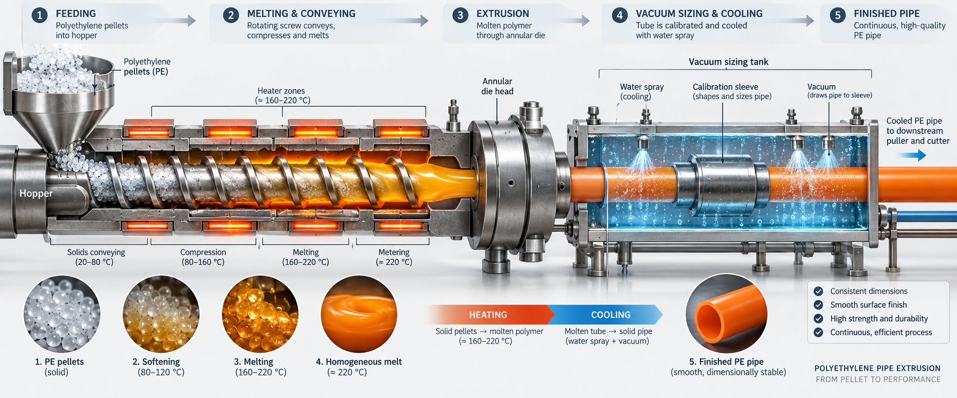
The Complete PE Pipe Extrusion Process Step by Step
Imagine a handful of small, unremarkable plastic pellets. Within minutes, they travel through a PE pipe making machine and emerge as a rigid, dimensionally precise pipe ready to carry pressurized water for decades. How does that transformation actually happen?
The PE pipe extrusion process follows a logical sequence - each stage building on the one before it. A disruption at any point ripples downstream, so understanding the full chain from resin to finished pipe is essential for anyone operating, purchasing, or specifying this equipment. Here is the complete journey, broken into its three major phases.
Raw Material Preparation and Feeding
Everything starts with the resin. Polyethylene arrives at the factory as small, uniform pellets - typically 3 to 5 mm in diameter - and the quality of the finished pipe depends heavily on how those pellets are handled before they ever reach the extruder.
First, consider moisture. While PE resins absorb less moisture than many other polymers, even small amounts of residual water cause problems. During extrusion, trapped moisture vaporizes inside the melt, producing bubbles, surface pitting, and internal voids that compromise pipe integrity. That's why most production lines include a drying step - usually hot-air drying - to bring moisture content within acceptable limits before processing begins. Alongside drying, raw materials are screened to remove dust, oversized particles, or foreign contaminants that could damage the screw barrel or create defects in the pipe wall.
The next critical element is consistent feeding. A PE pipe production line uses either volumetric or gravimetric dosing systems to deliver pellets into the extruder at a steady, controlled rate. Volumetric feeders meter material by volume, which works adequately for straightforward single-material runs. Gravimetric feeders, however, measure actual weight per unit time, automatically compensating for variations in pellet bulk density. For multi-layer co-extrusion or applications requiring tight wall-thickness tolerances, gravimetric dosing is the preferred choice because it keeps the material flow predictable.
Two resin properties deserve attention at this stage. The melt flow index (MFI) - a measure of how easily the molten polymer flows under specific test conditions - directly influences what processing temperatures and screw speeds the extruder will need. A lower MFI means higher melt viscosity, requiring more energy to push the polymer through the die. Oxidation induction time (OIT), on the other hand, indicates the resin's thermal stability: how long it can withstand elevated temperatures before degradation begins. Both values, found on the resin supplier's datasheet, guide the operator's initial parameter setup and prevent processing conditions that could damage the material before it even becomes a pipe.
Melting and Extrusion Through the Die Head
With pellets flowing steadily into the feed throat, the single-screw extruder takes over. This is where raw plastic becomes a workable melt - and it's far more nuanced than simply "heating up plastic."
Inside the barrel, the screw rotates continuously, performing three jobs simultaneously. In the feed zone, it grips incoming pellets and pushes them forward. In the compression zone, the channel depth decreases, compacting the pellets tightly together while barrel heaters raise the temperature. The combination of mechanical shear from screw rotation and conducted heat from the barrel zones gradually transforms solid granules into a viscous, homogeneous melt. Finally, in the metering zone, the screw delivers that melt forward at a consistent pressure and flow rate.
Why does homogeneity matter so much? Because any inconsistency in the melt - unmelted particles, temperature variations, or trapped air - transfers directly into the finished pipe as defects. Streaks, weak spots, and uneven wall thickness all trace back to poor melt quality. The barrel temperature profile is carefully zoned, gradually increasing from the feed section toward the die head, to promote thorough plasticization without overheating the polymer.
At the end of the extruder, the molten polyethylene enters the annular die head - the component that gives the pipe its shape. Inside the die, the melt flows around a central mandrel, spreading into a tubular profile. The gap between the die's outer ring and the inner mandrel determines the pipe's initial wall thickness, while the die's overall diameter sets the approximate outer diameter before sizing.
Consistent melt pressure at the die head is essential. Fluctuations cause surging - rhythmic variations in wall thickness along the pipe's length - that no amount of downstream adjustment can fully correct. Monitoring melt pressure serves as an early warning system: rising pressure may signal a partial blockage or degraded material, while dropping pressure could indicate feeding inconsistencies or worn screw flights.
Sizing, Cooling, Haul-Off, and Cutting
The soft, molten tube leaving the die head looks roughly like a pipe, but it has no structural rigidity and its dimensions aren't final. The downstream stations transform that fragile tube into a finished product with precise outer diameter, uniform wall thickness, and solid mechanical strength.
Here is the sequence, stage by stage:
- Vacuum calibration sizing - The hot tube enters a vacuum sizing tank immediately after the die. Inside, a calibration sleeve - a precision-machined metal tube matching the target outer diameter - surrounds the pipe. Vacuum pressure applied between the pipe's outer surface and the sleeve pulls the still-soft material outward against the sleeve's inner wall, locking in the outside diameter and roundness. Simultaneously, the pipe makes contact with cooling water, beginning the solidification process. This single station is where both shape and size are established, making it one of the most sensitive points on the entire line.
- Spray or immersion cooling - After initial sizing, the pipe passes through one or more cooling tanks. These may use water spray, full immersion, or a combination of both to remove heat progressively and solidify the pipe wall completely. Cooling must be uniform around the pipe's circumference; uneven cooling can introduce ovality, internal stress, or gradual dimensional drift that only becomes apparent later. Longer cooling tanks are needed for thicker-walled or larger-diameter pipes because they hold more thermal energy.
- Haul-off unit - A caterpillar-type or belt-type haul-off grips the cooled pipe and pulls it through the entire downstream section at a constant, precisely controlled speed. This is the mechanism that determines the draw ratio between the extruder output and the final pipe dimensions. If the haul-off pulls too fast, the pipe wall thins beyond specification; too slow, and material accumulates, causing bulging or uneven surfaces. The haul-off speed is typically set slightly faster than the natural extrusion rate to account for thermal shrinkage as the pipe cools.
- Cutting station - Once the pipe reaches the required length, a cutting unit activates. Planetary cutters rotate a blade around the pipe's circumference for clean, burr-free cuts on larger diameters. Chipless cutters use a blade that indents and snaps through the wall without producing chips - ideal for smaller pipes and environments where contamination must be minimized. In both cases, the cutter travels forward with the moving pipe during the cut so the line never stops.
- Stacking or coiling - Finished pipe lengths are automatically tilted onto a stacking rack or, for smaller-diameter flexible pipes, wound onto coils for easier transport and installation.
Here's the systems-level concept that ties everything together: the extruder's output rate, the haul-off pulling speed, and the cutter's activation timing must all be synchronized. The extruder determines how much molten PE is produced per minute. The haul-off controls how quickly that material is drawn into its final dimensions. The cutter must fire at precisely the right moment to hit the target cut length without interrupting the continuous process. If any one of these three elements drifts independently, you'll see it in the pipe - as wall-thickness variation, length inaccuracy, or surface marks at the cut point.
This synchronization is what makes a PE pipe making machine a true production system rather than a collection of separate machines. Each unit depends on the others, and the quality of the finished pipe reflects how well the entire chain works in harmony.
Of course, even perfect synchronization can't compensate for a worn extruder screw or an undersized cooling tank. The individual components that make up the production line - and the specifications that determine their performance - are just as important as the process they execute.
Key Components of a PE Pipe Production Line Explained
A well-orchestrated extrusion process means little if the individual machines executing it aren't up to the task. Each component in a PE pipe making machine carries a specific responsibility - and the specifications you choose for each one directly shape your output capacity, dimensional accuracy, and long-term reliability. Think of it like an orchestra: every instrument must be tuned correctly, or the performance falls apart.
Let's break down each unit in the order the material encounters it, starting with the most critical component of all.
Single-Screw Extruder - The Heart of the Line
If one component deserves the title of "heart" of the production line, it's the single-screw extruder. Its job sounds simple - melt polyethylene pellets and push the molten polymer forward at a consistent rate - but the engineering behind it determines almost everything about pipe quality and throughput.
Three specifications define an extruder's capability more than any others:
- Screw diameter - Measured in millimeters (commonly 45 mm, 65 mm, 75 mm, 90 mm, or 120 mm for PE pipe applications), the screw diameter sets the upper limit on output volume. A larger screw processes more material per revolution, enabling higher throughput and bigger pipe diameters.
- L/D ratio (length-to-diameter ratio) - This describes how long the screw is relative to its diameter. PE pipe extruders typically use L/D ratios of 30:1 to 33:1. A higher ratio provides more residence time for thorough melting and mixing, which is critical for achieving the melt homogeneity that pressure-rated pipes demand.
- Motor power - The drive motor must deliver sufficient torque to rotate the screw against the resistance of compacting and melting polymer. Undersized motors limit output and risk overheating under sustained load; oversized motors waste energy.
The screw itself is far from a generic component. Its geometry - the depth and pitch of the flights in the feed, compression, and metering zones - is specifically designed for PE processing. Some screws incorporate dedicated mixing sections or barrier flight designs that separate unmelted solids from the melt pool, improving plasticization quality and output consistency.
Here's a detail many buyers overlook: the screw and barrel are the most critical wear components on the entire line. Every rotation grinds polymer against metal surfaces under high pressure and temperature. Over thousands of hours, the flights wear down, the barrel bore widens, and the clearance between screw and barrel increases. That growing gap reduces pumping efficiency, introduces melt inconsistency, and ultimately degrades pipe quality - often so gradually that operators don't notice until defect rates climb.
Material composition makes all the difference. Nitrided steel barrels offer solid baseline wear resistance for standard PE resins. Bimetallic alloy barrels - with a hard protective lining typically 1 to 2 mm thick fused to the barrel's inner surface - provide substantially longer service life, especially when processing filled compounds, recycled material, or abrasive additives. The same principle applies to screw surfaces, where hard-facing coatings extend flight life and maintain tight clearances.
When a screw or barrel does wear beyond tolerance, replacement quality matters enormously. Manufacturers like NANHAIYA specialize in custom and replacement single screw barrels engineered specifically for PE pipe extrusion applications. Their offerings cover different resin types and output requirements, giving operators the flexibility to source precision-matched wear parts without being locked into OEM-only supply chains. Having access to a specialized supplier for these components can significantly reduce downtime during scheduled maintenance and keep melt quality at peak levels.
Extrusion Die Head and Mandrel
If the extruder creates the melt, the die head gives it shape. This component sits at the front of the extruder and transforms a solid column of molten polyethylene into a hollow tubular profile - the pipe's initial form before sizing.
Inside the die head, the melt stream flows around a central mandrel - a torpedo-shaped core - and spreads into an annular channel. Spider legs or a spiral distributor support the mandrel while ensuring the melt wraps evenly around it without leaving weld lines or thin spots. The gap between the outer die ring and the mandrel's tip determines the pipe's initial wall thickness.
Adjustability is key. Centering bolts around the die allow operators to shift the mandrel's position relative to the outer ring, compensating for any wall-thickness imbalance around the pipe's circumference. This adjustment is one of the most common interventions on a running production line - even a fraction of a millimeter offset can produce measurable wall-thickness variation.
Die heads are typically sized for a specific diameter range. Producing pipes outside that range requires swapping to a different die, which is why many manufacturers invest in multiple die sets to cover their full product catalog. The die land length - the straight section at the exit - also influences surface quality. A longer land gives the melt more time to stabilize before exiting, reducing die swell and surface irregularities.
Vacuum Sizing Tank and Cooling System
The moment the soft, molten tube exits the die, it's dimensionally unstable. Without immediate intervention, gravity, air pressure, and internal stresses would distort it within seconds. The vacuum sizing tank is the station that freezes the pipe into its final shape.
Inside the tank, a precision-machined calibration sleeve surrounds the pipe. Vacuum pressure - carefully regulated - pulls the pipe's outer surface outward against the sleeve's inner wall, establishing the target outer diameter and roundness. Simultaneously, cooling water contacts the pipe surface, rapidly extracting heat from the outside in. The result is a solidified outer skin that holds shape while the interior continues cooling.
Getting the vacuum level right is critical. Too much vacuum distorts the pipe or causes the outer surface to drag against the sleeve, leaving marks. Too little allows the pipe to shrink away from the sleeve, producing undersized or out-of-round output. The calibration sleeve itself must be smooth, correctly sized, and free of scratches or buildup - any imperfection transfers directly to the pipe surface.
Downstream of the vacuum tank, one or more spray cooling tanks or immersion cooling tanks continue the heat-removal process. These are typically several meters long - the exact length depends on pipe diameter, wall thickness, and line speed. Thicker-walled pipes retain more heat and need longer cooling paths. Water temperature and flow rate in these tanks should be controlled to ensure gradual, uniform cooling that minimizes residual stress inside the pipe wall.
Haul-Off Unit and Cutting Station
The haul-off unit is the component that sets the pace for the entire downstream section. Positioned after the cooling tanks, it grips the cooled pipe and pulls it through the line at a precisely controlled, constant speed.
Most PE pipe lines use caterpillar-type haul-offs, which feature two or more continuous rubber-padded tracks that clamp around the pipe and drive it forward. The clamping force must be strong enough to maintain grip without deforming the pipe surface - a balance that's especially important for thinner-walled products. For larger-diameter pipes, haul-off units may use multiple tracks (up to 12 in some configurations) arranged around the circumference to distribute the gripping force evenly.
Speed stability is non-negotiable. Even minor fluctuations in haul-off speed translate directly into wall-thickness variation along the pipe's length. Modern servo-driven haul-offs offer closed-loop speed control, maintaining pulling speed within very tight tolerances regardless of load changes. The haul-off force itself can range from around 100 N for small-diameter pipes to over 10,000 N for heavy, large-diameter products.
At the end of the line, the cutting station trims the continuously moving pipe to the specified length. Two main cutter types dominate PE pipe production:
- Planetary cutters - A blade orbits around the pipe, making a clean circumferential cut. Ideal for medium to large diameters and thicker walls.
- Chipless cutters - A blade presses into the pipe wall and shears through without removing material. These produce no chips or dust, making them well-suited for smaller diameters and cleanroom-sensitive applications.
In both cases, the cutter clamps onto the pipe and travels with it during the cut, so the extrusion process never needs to pause. After the cut is complete, the cutter releases and resets to its starting position before the next cycle.
The table below summarizes every major PE pipe extrusion line component, what it does, and what to look for when evaluating or specifying equipment:
| Component | Primary Function | Key Specifications to Evaluate | Impact on Pipe Quality |
|---|---|---|---|
| Single-Screw Extruder (with Screw & Barrel) | Melts PE resin and delivers a homogeneous melt at consistent pressure and flow rate | Screw diameter, L/D ratio (30-33:1 for PE), motor power, screw/barrel material (nitrided steel or bimetallic alloy), output capacity (kg/h) | Directly determines melt quality, throughput, and consistency; worn screw/barrel leads to poor homogeneity, reduced output, and surface defects |
| Extrusion Die Head & Mandrel | Shapes the molten polymer into a tubular profile with controlled wall thickness | Diameter range coverage, die gap adjustability, number of centering bolts, land length, suitability for co-extrusion (multi-layer heads) | Controls wall thickness uniformity, concentricity, and surface finish; misaligned die causes eccentric wall distribution |
| Vacuum Sizing Tank | Establishes precise outer diameter and roundness through vacuum calibration and initial cooling | Vacuum pressure range and control precision, calibration sleeve material and sizing, water flow rate, tank length | Determines dimensional accuracy (OD, roundness); incorrect vacuum or worn sleeves cause undersized, oversized, or oval pipes |
| Spray / Immersion Cooling Tanks | Removes residual heat to fully solidify the pipe wall | Total cooling length, water temperature control, spray nozzle arrangement, number of cooling zones | Insufficient or uneven cooling causes ovality, residual stress, warping, and pipe bowing after cut |
| Haul-Off Unit | Pulls the pipe through all downstream stations at a constant, controlled speed | Number of tracks (2-12), maximum haul-off force (100-10,000+ N), speed range and stability, servo vs. standard drive, clamping force adjustability | Speed variations directly cause wall-thickness fluctuation; excessive clamping deforms the pipe surface |
| Cutting Station | Cuts the continuous pipe to specified lengths without stopping the line | Cutter type (planetary or chipless), maximum pipe diameter capacity, cut length accuracy, travel-with-pipe capability, chip collection system | Poor cutter performance causes uneven end faces, burrs, out-of-spec lengths, or surface damage at the cut point |
| Pipe Stacker / Coiler | Collects finished pipe lengths onto racks or winds small-diameter pipes into coils | Stacking capacity, coil diameter range, winding speed synchronization, automatic vs. manual operation | Improper handling at this stage can scratch surfaces or deform still-warm pipes, especially thin-walled products |
Every row in that table represents a potential bottleneck - or a potential advantage - depending on how well the component is specified and maintained. The extruder and its screw barrel stand out because their condition directly governs melt quality, which cascades through every downstream station. A perfectly tuned die, flawless vacuum sizing, and precision haul-off speed cannot compensate for an inconsistent melt leaving a worn-out extruder.
Yet even with ideal equipment, the performance you get depends heavily on what you feed into it. The grade of PE resin you choose - and how well your machine parameters match that resin's processing characteristics - can make the difference between pipes that exceed specifications and pipes that never pass quality control.
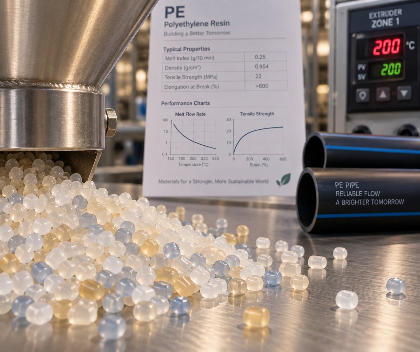
PE Material Grades and How They Affect Machine Settings
You could own the most advanced PE pipe making machine on the market, staff it with experienced operators, and still produce substandard pipes - if you're running the wrong resin grade or haven't matched your processing parameters to the material. Resin selection isn't just a purchasing decision. It's a machine-setting decision, a die-selection decision, and a cooling-system decision all rolled into one.
Yet this connection between material grade and equipment configuration is one of the least discussed topics in the industry. Let's fix that.
Understanding PE Resin Grades for Pipe Production
When you see designations like PE63, PE80, PE100, or PE100-RC on a resin datasheet, those numbers aren't arbitrary. They represent the material's Minimum Required Strength (MRS) - the hoop stress, in megapascals, that the resin is guaranteed to sustain over a 50-year design life, multiplied by ten. So PE80 delivers an MRS of 8.0 MPa, while PE100 delivers 10.0 MPa - a 25% strength advantage that has real consequences for how your production line operates.
Here's the practical lineup you'll encounter:
- PE63 - Largely obsolete. You'll rarely encounter it in new pipe production, though some legacy specifications still reference it.
- PE80 - An older workhorse grade still used for gas distribution, small-bore pipes, and legacy water networks. Often based on unimodal molecular structures, PE80 is generally easier to process but requires thicker walls to achieve the same pressure rating as PE100.
- PE100 - The modern standard for new pressure pipe worldwide. Its bimodal molecular structure blends high-molecular-weight fractions (for strength and crack resistance) with low-molecular-weight fractions (for processability). Because it's stronger, PE100 enables thinner walls at the same pressure class - meaning less material per meter of pipe and a larger internal bore for improved flow.
- PE100-RC - Same MRS and pressure rating as standard PE100, but with greatly enhanced resistance to slow crack growth and point loads. It's the grade for tough installations - trenchless methods, stony backfill, no-sand-bed bedding - where toughness, not higher pressure, is the upgrade.
- PE-RT (Raised Temperature Resistance) - Designed specifically for hot water applications like underfloor heating systems. PE-RT maintains its long-term hydrostatic strength at elevated service temperatures where standard HDPE grades would lose performance.
Why does this matter for your equipment? Because that 25% strength gap between PE80 and PE100 translates directly into different wall thicknesses for the same pressure class. Thinner walls mean different die gap settings, altered cooling demands (less material to solidify), and adjusted haul-off speeds. A production line optimized for PE80 won't automatically produce specification-compliant PE100 pipes without recalibration - and vice versa.
In North America, you'll also encounter the designation PE4710, which is the ASTM near-equivalent of PE100, classified through a different testing methodology but delivering comparable performance.
How Material Properties Influence Machine Parameters
Switching between PE grades isn't as simple as swapping the bag of pellets in the hopper. Each grade carries a distinct set of physical properties that require corresponding adjustments across the extrusion line.
Melt Flow Index (MFI) is the property that affects machine settings most directly. MFI quantifies how easily molten polymer flows under standardized test conditions - think of it as a viscosity indicator. PE100 grades typically exhibit a lower MFI (roughly 0.2 to 0.4 g/10min at 190 degrees C/2.16 kg) compared to PE80 grades (around 0.3 to 0.7 g/10min under the same conditions). A lower MFI means higher melt viscosity, which demands more energy from the extruder motor, generates higher melt pressures, and typically requires elevated barrel temperature profiles to achieve adequate plasticization and flow through the die.
Density also plays a role. Higher-density PE grades crystallize differently during cooling, which influences how quickly the pipe solidifies in the sizing and cooling tanks. A denser resin may require adjusted cooling intensity or longer cooling paths to prevent residual stress buildup inside the pipe wall.
Thermal stability varies between grades, and this directly governs how much processing headroom the operator has. PE100's bimodal structure, while stronger in service, can be more sensitive to thermal degradation if barrel temperatures climb too high. PE-RT grades, meanwhile, operate within a processing temperature window of roughly 180 to 210 degrees C and are particularly sensitive to excessive shear - pushing temperatures too high or running screw speeds too fast risks decomposing the very molecular characteristics that give PE-RT its elevated-temperature performance.
The practical upshot? PE100 generally runs hotter across all barrel zones than PE80 - on the order of 10 to 15 degrees C higher - because its higher molecular weight and lower MFI demand more thermal and mechanical energy to achieve a homogeneous melt. PE-RT grades, by contrast, call for a "low temperature, low pressure" extrusion philosophy to preserve material integrity, often with specialized screw designs that minimize shear heating.
Screw speed adjustments follow a similar logic. Higher-viscosity resins generate more shear heat at any given RPM, which means that a screw speed perfectly suited for PE80 may overheat PE100 through viscous dissipation alone - even if the barrel heater setpoints are identical. Monitoring actual melt temperature at the die exit, rather than relying solely on barrel zone readings, becomes essential when switching grades.
Practical Tips for Material-Machine Matching
Getting the resin-to-machine relationship right doesn't require guesswork. It requires a disciplined approach and attention to the data your equipment and material suppliers already provide. Here are the guidelines experienced operators follow:
- Always consult the resin supplier's datasheet for recommended processing temperature ranges, MFI values, and drying requirements before running any new grade. These datasheets are grade-specific and reflect the manufacturer's extensive testing - they are your most reliable starting point.
- Run trial extrusions when switching grades. Even moving between two PE100 resins from different suppliers can introduce subtle differences in melt behavior. Start with the datasheet-recommended profile, produce a short run, measure wall thickness and surface quality, and fine-tune from there before committing to full production.
- Monitor melt pressure as a real-time viscosity indicator. A rising melt pressure at the die head - with no change in screw speed or temperature settings - signals a shift in material viscosity. This could mean the new grade is behaving differently than expected, the resin lot has a slightly different MFI, or moisture is affecting melt consistency. Treat unexplained pressure changes as an immediate cue to investigate.
- Verify that your screw design is compatible with the target resin's viscosity range. A screw optimized for the relatively easy flow of PE80 may not generate sufficient mixing or pressure for a high-viscosity PE100. Conversely, an aggressive mixing screw designed for PE100 could overshear a PE-RT grade, causing degradation. If you plan to process a wide range of PE grades, discuss screw geometry options with your equipment supplier.
- Adjust cooling intensity when changing wall thickness. Shifting from PE80 to PE100 at the same pressure class usually means producing a thinner wall, which solidifies faster and may require reduced cooling water flow to prevent overcooling and thermal shock. Conversely, maintaining the same SDR with a higher-MRS grade gives you a higher pressure rating but the same wall - meaning your cooling setup may not need adjustment.
- Document every parameter set. When you find the sweet spot for a particular resin grade and pipe size, record the full parameter recipe - barrel zone temperatures, screw speed, melt pressure, haul-off speed, vacuum level, and cooling water temperatures. Modern PLC systems let you store and recall these recipes instantly, eliminating setup guesswork on repeat runs.
The relationship between material and machine is a two-way street. The resin dictates what the equipment must deliver; the equipment's capabilities determine which resins you can process profitably. Understanding both sides of that equation is what separates a production line that merely runs from one that consistently delivers pipes meeting every specification.
Material grade and machine parameters, however, are just two pieces of the selection puzzle. Matching the right production line to your business requires a broader evaluation - one that considers pipe diameter targets, output volumes, applicable standards, and the long-term support behind the equipment you buy.
How to Select the Right PE Pipe Making Machine for Your Needs
Knowing your resin grades and process parameters is one thing. Translating that knowledge into a purchase decision - choosing the specific PE pipe making machine configuration that fits your market, your budget, and your factory floor - is an entirely different challenge. Get it right, and you have a production line that pays for itself within a few years. Get it wrong, and you're stuck with equipment that either can't reach your target output or sits idle because it's oversized for the demand you actually have.
The difference between the two outcomes usually comes down to how thoroughly you define your requirements before you ever contact a supplier.
Defining Your Production Requirements
Before evaluating any equipment, you need clear answers to a specific set of questions. Skipping even one of these can lead to a mismatch between what you buy and what you actually need to produce. Think of this as your PE pipe machine buyer guide checklist - the foundation every purchasing decision should rest on:
- Target pipe diameter range - What is the smallest and largest outer diameter you plan to produce? A line designed for 16-63 mm pipes uses a fundamentally different extruder and die setup than one built for 315-1200 mm pipes.
- Wall thickness specifications - Are you producing thin-wall SDR 17 pipes for low-pressure applications, or thick-wall SDR 9 pipes for high-pressure gas distribution? Wall thickness directly impacts required extruder output, die design, and cooling tank length.
- Required output volume - Define your target in both kg/h and m/min for your most common pipe sizes. This determines extruder size, cooling capacity, and whether a single line or multiple parallel lines make more economic sense.
- Pipe application and relevant standards - Municipal water supply pipes must meet standards like ISO 4427, while gas distribution pipes follow ISO 4437. Telecommunications ducting, irrigation, and industrial applications each carry their own specifications. The applicable standard dictates dimensional tolerances, pressure ratings, and testing requirements - all of which influence equipment selection.
- Budget range and total cost of ownership - Consider not just the purchase price, but installation costs, utility consumption, spare parts pricing, and expected maintenance intervals over the first five to ten years of operation.
- Available factory space and utilities - PE pipe lines are linear and can stretch 30 to 60 meters or more depending on pipe diameter and cooling requirements. Confirm that your facility can accommodate the full line length, ceiling height for pipe handling, water supply for cooling, compressed air, and electrical capacity.
Sounds like a lot of homework? It is. But every experienced pipe manufacturer will tell you the same thing: the projects that succeed are the ones where the buyer clearly understands the production target and machine configuration before placing the order, not after.
Matching Machine Specifications to Your Needs
With your requirements defined, the next step is matching them to actual equipment specifications. The extruder size for HDPE pipe diameter range is the single most important correlation to understand - it determines your throughput ceiling and the range of pipe sizes you can produce on one line.
Extruder screw diameter is the primary variable. Output scales roughly with the square of the screw diameter, which means doubling the screw size doesn't just double your capacity - it can increase it by a factor of four. A 65 mm single-screw extruder handles small to mid-range pipes and delivers moderate throughput, while a 120 mm or 150 mm screw is built for large-diameter, high-volume production.
The table below maps common pipe diameter ranges to typical extruder sizes and approximate output capacities for PE pipe production. These are representative ranges, not absolute values - actual performance varies with screw design, L/D ratio, resin grade, and operating conditions:
| Pipe Diameter Range (OD) | Typical Extruder Screw Diameter | Approximate Output Capacity (kg/h) | Common Applications |
|---|---|---|---|
| 16 - 63 mm | 45 - 65 mm | 80 - 200 | Drip irrigation, cable ducting, small water connections |
| 63 - 250 mm | 65 - 90 mm | 150 - 450 | Water supply mains, gas distribution, industrial piping |
| 250 - 630 mm | 90 - 120 mm | 350 - 1,000 | Municipal water networks, sewer force mains, mining |
| 630 - 1200 mm+ | 120 - 150 mm+ | 700 - 1,600+ | Large-diameter water transmission, outfall pipelines, major infrastructure |
Die head selection follows a similar logic. Each die head covers a defined diameter range - you can't produce a 630 mm pipe through a die designed for a maximum of 250 mm. Many manufacturers purchase multiple die sets to cover their full product catalog, swapping heads when shifting between pipe size families. If your product range spans a wide diameter spectrum, confirm that the line you're evaluating supports quick die changeovers to minimize downtime.
Then there's the single-layer versus multi-layer question. A standard single-layer line is simpler, less expensive, and perfectly adequate for most solid-wall PE pipe applications. Multi-layer co-extrusion lines - which require additional extruders feeding into a specialized co-extrusion die head - add complexity and cost but enable valuable capabilities: colored outer skins for product identification, recycled material in the core layer to reduce raw material costs, or barrier layers for specialized chemical resistance. The trade-off is straightforward - if your market or standards require multi-layer construction, the added investment is unavoidable. If not, a well-built single-layer line delivers excellent results at a lower entry cost.
Evaluating Manufacturers and After-Sales Support
Here's a reality that many first-time buyers underestimate: the PE pipe production line selection criteria that matter most aren't just about machine specifications on paper. They're about what happens after installation - when a screw barrel wears out at month eighteen, when your operator needs troubleshooting support at 2 AM during a critical production run, or when you want to expand into a new pipe diameter range and need a compatible die set.
When evaluating equipment suppliers, dig into these practical areas:
- Spare parts availability and lead times - How quickly can you get replacement calibration sleeves, heater bands, gearbox components, or screw barrels? A three-month wait for a critical part can cost far more in lost production than the part itself.
- Technical training - Does the supplier provide operator training during commissioning? Are follow-up training sessions available as you onboard new staff or introduce new products?
- Installation and commissioning support - Will the manufacturer send engineers to your site for installation, alignment, and first-run supervision? Remote support via video call is helpful, but nothing replaces hands-on commissioning for a complex production line.
- Component sourcing flexibility - This is a detail many buyers overlook until it matters. The ability to source replacement wear parts - especially screw barrels, the highest-wear components on the line - from specialized third-party suppliers rather than exclusively from the original equipment manufacturer provides real operational advantages. It creates competitive pricing, faster delivery options, and the freedom to specify upgraded materials (like bimetallic alloys) that the OEM may not offer as standard. Being locked into a single source for critical consumables introduces supply chain risk that compounds over the life of the equipment.
A PE pipe making machine is a capital investment measured in decades, not months. The supplier relationship extends far beyond the initial purchase order - it shapes your maintenance costs, your uptime, and ultimately your competitiveness in the market you serve.
Equipment specifications and supplier support get you a capable production line. But turning that capability into consistently high-quality output - day after day, shift after shift - depends on the control systems that coordinate every component in real time and the automation features that reduce human error. That's the layer of intelligence sitting on top of the mechanical hardware, and it's evolving rapidly.
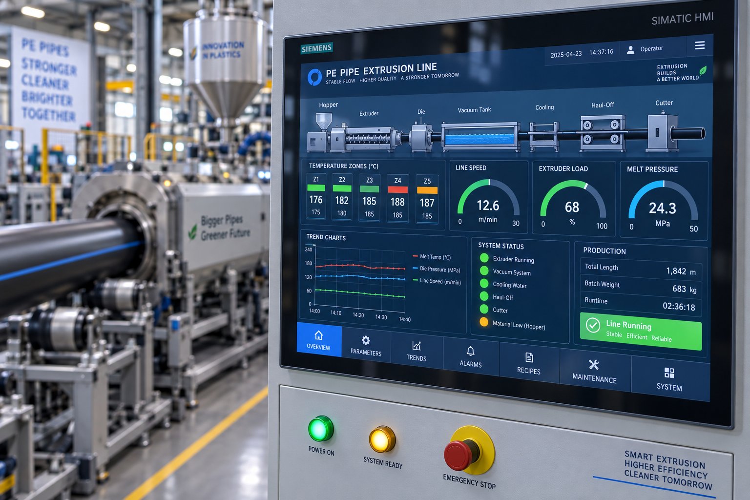
Control Systems and Automation in Modern PE Pipe Lines
A PE pipe making machine can have perfectly sized components - the right extruder, the right die, the right cooling tanks - and still produce inconsistent output if those components aren't communicating with each other. The control system is the intelligence layer that ties everything together, coordinating barrel temperatures, screw speed, haul-off pulling force, vacuum pressure, and cutter timing into a single, repeatable production logic.
Yet when buyers compare equipment quotations, control systems often receive the least scrutiny. Two lines may both list "PLC + HMI" on the spec sheet and behave very differently on the factory floor. One might only display temperature readings on a screen. The other might coordinate every process variable, store complete product recipes, and automatically intervene when melt pressure drifts outside the safe range. Understanding what your PLC control system for PE pipe extrusion line actually manages - versus what it merely displays - is the difference between a line that runs itself and one that depends entirely on your best operator's memory.
PLC and HMI Touchscreen Interfaces
The programmable logic controller (PLC) is the brain behind the production line. It executes the control logic that governs how each station responds to real-time conditions: adjusting barrel zone heaters when thermocouples detect a temperature drift, modulating haul-off motor speed to maintain a target pull rate, triggering the cutter at precise pipe length intervals, and activating alarms or protective shutdowns when melt pressure, motor load, or temperature readings cross predefined thresholds.
The human-machine interface (HMI) - typically a color touchscreen panel mounted at the operator station - is the window into all of that logic. A well-designed HMI displays real-time values for every critical parameter: barrel and die zone temperatures, screw RPM, melt pressure, haul-off speed, vacuum level, and motor current draw. It also shows alarm histories, trend graphs, and active fault messages so operators can spot developing problems before they become pipe defects.
But the real daily-use value of the HMI lies in recipe management. Imagine you produce six different pipe diameters in two PE grades across a typical production week. Each product requires its own combination of barrel temperatures, screw speed, die settings, haul-off speed, vacuum pressure, and cutter length. Without a recipe system, your operators reconstruct those settings from memory or handwritten notes every time they change over - a process that generates startup scrap and introduces human error.
A complete recipe system stores all of those parameters as a named product setup. When the operator selects a recipe, the PLC loads the entire parameter set as a known baseline. It doesn't eliminate the need for fine-tuning, but it dramatically reduces changeover time and ensures that the starting point is consistent regardless of which operator is running the shift. The key question to ask any supplier: does the recipe store only temperature zones, or does it include speed ratios, downstream settings, alarm thresholds, and cutter parameters? A partial recipe that covers only temperatures leaves the most important variables to chance.
Automation Levels and Industry 4.0 Integration
Not every production facility needs - or can justify - the same level of automation. The automation levels in pipe making machines span a wide spectrum, and understanding where your operation falls helps you invest wisely rather than overspending on features you won't use or underinvesting and hitting a capability ceiling within a year.
At the basic end, a semi-automatic line uses a PLC primarily for temperature control and simple alarm display. Operators manually set screw speed, adjust haul-off rates by observation, and rely on periodic offline measurements to verify wall thickness and diameter. This approach works for low-volume operations producing a limited range of pipe sizes, but it's entirely dependent on operator skill and attention.
Mid-range systems add meaningful coordination. Gravimetric dosing feeds material by measured weight rather than volume, eliminating output variations caused by changes in pellet bulk density. Servo-driven haul-offs maintain pulling speed within tight tolerances through closed-loop feedback - if the load on the pipe changes (from cooling tank drag, for example), the servo adjusts instantly rather than waiting for the operator to notice. Recipe storage becomes comprehensive, covering all line parameters rather than just temperature zones. Alarm logic goes beyond simple display: the system can automatically reduce screw speed if melt pressure exceeds a threshold, or trigger a controlled line stop if motor current spikes dangerously.
Advanced, fully automated lines push into Industry 4.0 integration for pipe production. Inline wall-thickness measurement - using ultrasonic gauges or radar-based sensors - continuously monitors pipe dimensions at multiple points around the circumference, feeding data back to the PLC in real time. When the system detects that wall thickness is trending toward the lower tolerance limit, it can automatically adjust haul-off speed or material feed rate to correct the drift before any out-of-spec pipe is produced. This closed-loop approach has been shown to reduce material consumption by 2% or more while simultaneously improving dimensional consistency.
Remote monitoring PE pipe extrusion equipment via IoT connectivity takes visibility beyond the factory floor. Web-enabled dashboards let production managers and engineers check line status, view trend data, and receive alarm notifications from anywhere - on a tablet in the office, a phone at home, or a laptop halfway around the world. Every parameter the PLC records - temperatures, speeds, pressures, alarms, recipe changes, production counts - gets logged with timestamps, creating a complete digital history of each production run.
That data trail serves two powerful purposes. First, it enables quality traceability: if a customer questions a batch of pipe six months after delivery, you can pull up the exact processing conditions under which it was produced. Second, it supports predictive maintenance: gradually rising melt pressure over weeks may indicate screen pack loading or barrel wear, while increasing motor current at the same screw speed can signal screw flight degradation - patterns that a human operator might miss but a data logging system captures clearly.
The comparison below maps these three tiers against the features that matter most on the production floor:
| Feature | Basic (Semi-Automatic) | Mid-Range (Coordinated) | Advanced (Fully Automated / Industry 4.0) |
|---|---|---|---|
| Recipe Storage | Temperature zones only, or none | Comprehensive - temperatures, speeds, vacuum, cutter settings, alarm limits | Full recipe with automatic recall and parameter verification before run start |
| Auto-Alarm Diagnostics | Simple alarm display on screen; no automatic response | Alarm-triggered actions (speed reduction, controlled stop) for critical faults | Multi-level alarm logic with root-cause guidance, automatic corrective actions, and alarm history analytics |
| Remote Monitoring Capability | None - operator must be at the panel | Optional local network access; basic status view | Full IoT connectivity with cloud or web-based dashboards, mobile alerts, and remote parameter viewing |
| Wall Thickness Feedback Control | Manual offline measurement only | Inline measurement display (ultrasonic or radar) without automatic correction | Closed-loop feedback: inline measurement drives automatic haul-off or feed rate adjustment to maintain target dimensions |
| Data Logging | Minimal or none | Basic logging of key parameters with shift-level reports | Continuous logging of all parameters with timestamped records, trend analysis, and export capability for quality audits |
| Material Dosing | Volumetric feeder | Gravimetric dosing with weight-based output monitoring | Gravimetric dosing integrated with closed-loop output control and material consumption tracking |
| Haul-Off Speed Control | Standard AC drive with manual speed setting | Servo drive with closed-loop speed stability | Servo drive with automatic speed adjustment based on inline dimensional feedback |
Where should you invest? That depends on your production volume, product tolerance requirements, and workforce capabilities. A factory producing irrigation pipe in a limited diameter range may operate profitably with a mid-range system. A manufacturer supplying pressure-rated PE100 pipe to municipal water authorities - where every meter must meet ISO 4427 tolerances and full traceability documentation is expected - will find that advanced automation pays for itself through reduced scrap, lower material consumption, and the ability to produce auditable quality records automatically.
Regardless of the automation tier, remember that a control system's true value shows up not when everything runs smoothly, but when something goes wrong. A rising melt pressure, an unexpected temperature spike, an eccentric wall distribution developing over several hours - these are the moments where intelligent alarm logic, trend visibility, and closed-loop correction separate a minor process adjustment from a major quality incident.
Speaking of things going wrong: even the best control systems can't prevent every defect. Material contamination, mechanical wear, and environmental factors still introduce problems that require human diagnosis and intervention. Knowing what the most common PE pipe extrusion defects look like - and what causes them - is the practical knowledge that keeps a production line running when alarms do fire.
Troubleshooting Common PE Pipe Extrusion Defects
A PE pipe making machine can be properly specified, freshly commissioned, and running the correct resin grade - and still produce pipes with visible flaws. Surface roughness, dimensional inconsistencies, and structural weak points don't always announce themselves through alarm screens. Some develop gradually as components wear. Others appear suddenly when a new batch of resin behaves differently than the last. Either way, diagnosing the root cause quickly is the skill that separates a brief production hiccup from hours of wasted material and downtime.
This PE pipe extrusion troubleshooting guide covers the defects you're most likely to encounter, explains what causes them, and walks through corrective actions you can take on the production floor.
Surface Defects and Die Lines
Run your hand along a finished PE pipe and you expect a smooth, uniform surface. When you feel roughness, ridges, or see streaks running lengthwise along the pipe, something upstream is disrupting the melt quality or die flow.
Rough or pitted outer surfaces typically trace back to one of three sources. Contaminated resin - dust, moisture, or foreign particles mixed into the pellets - creates localized imperfections as those contaminants pass through the die. Incorrect melt temperature is another frequent culprit: too low, and the polymer isn't fully plasticized, leaving unmelted granules that drag across the die land and gouge the surface. Too high, and the resin begins to degrade, producing gas pockets and discoloration that show up as pitting or rough patches.
Then there's the screw barrel itself. Over thousands of operating hours, the screw flights and barrel bore wear down, increasing the clearance between the two. That growing gap allows material to slip backward rather than being pushed forward efficiently, creating temperature inconsistencies and poorly mixed melt zones. A worn screw barrel that fails to homogenize the melt will produce surface defects on extruded PE pipes that no amount of die adjustment can fix - because the problem exists before the material ever reaches the die.
Die lines - thin, continuous streaks running parallel to the extrusion direction - result from material buildup on the die land surface, scratches or nicks on the die lip, or uneven flow distribution around the mandrel. Cleaning the die land, polishing any surface damage, and verifying that the spider legs or spiral distributor are directing melt evenly will usually resolve these streaks. If die lines persist after cleaning, the die itself may need refurbishment or replacement.
General corrective approaches for surface defects include:
- Verify resin cleanliness and moisture content before feeding into the extruder
- Review and adjust barrel temperature profiles according to the resin supplier's recommended processing window
- Inspect the die land for buildup, scratches, or wear marks and clean or polish as needed
- Evaluate screw and barrel wear - measure clearances and replace components if they exceed tolerance
- Ensure adequate sizing sleeve cooling so the pipe surface solidifies before contacting any downstream equipment
Uneven Wall Thickness and Ovality Problems
Few defects cause more rejection than uneven wall thickness in HDPE pipe extrusion. A pipe that measures 10% thicker on one side than the other fails dimensional standards, wastes material on the heavy side, and may not withstand design pressure on the thin side. Ovality - when the pipe's cross-section is egg-shaped rather than perfectly round - creates problems at joints and fittings, where a round pipe is assumed.
Die head misalignment is the most common cause of eccentric wall distribution. If the mandrel isn't centered precisely within the outer die ring, more material flows through the wider gap, producing a thicker wall on one side. The fix involves adjusting the centering bolts - small set screws positioned around the die circumference that allow operators to shift the mandrel's position relative to the outer ring. This adjustment is delicate; even fractions of a millimeter matter, and it should be checked with an ultrasonic wall thickness gauge at multiple points around the pipe circumference.
Inconsistent haul-off tension introduces a different type of wall variation. If the gripping tracks aren't applying equal pressure on all sides, or if the haul-off speed fluctuates, the pipe stretches unevenly as it's pulled through the downstream section. Servo-driven haul-off units largely eliminate speed-related fluctuations, but track condition and alignment still require regular inspection.
Vacuum calibration issues play a significant role in both wall thickness and ovality. If the vacuum level is too low or unevenly distributed within the sizing tank, the pipe doesn't press uniformly against the calibration sleeve. One section may pull tightly to the sleeve while another sags away from it, producing both eccentric dimensions and an oval profile. The condition of the calibration sleeve itself matters just as much - a scratched, worn, or incorrectly sized sleeve transfers those imperfections directly to the pipe surface and geometry.
Uneven cooling compounds these problems further. If spray nozzles in the cooling tanks aren't distributing water uniformly around the pipe circumference, one side solidifies faster than the other. The side that cools first shrinks and stiffens while the opposite side remains soft and vulnerable to deformation. Monitoring the cooling rate for uniformity and maintaining consistent water distribution in every cooling zone is essential for maintaining roundness throughout the full solidification process.
Other Common Extrusion Issues
Beyond surface quality and dimensional accuracy, several other defects can undermine the performance and marketability of your PE pipes. Each one points to a different area of the production line.
Melt fracture, often called "shark skin," appears as a fine, repetitive roughness or a wrinkled texture on the pipe's outer surface. It occurs when the molten polymer experiences excessive shear stress as it exits the die - essentially, the melt is being pushed through the die gap faster than the polymer's molecular structure can accommodate. The surface layer tears and re-forms in a rhythmic pattern, producing that characteristic sharkskin texture. In more severe cases, the entire pipe surface becomes distorted with deep, irregular ridges. To fix melt fracture in pipe extrusion, you'll need to reduce the shear rate at the die exit - either by lowering screw speed, raising melt temperature to reduce viscosity, or widening the die gap slightly. In some cases, switching to a resin grade with a higher melt flow index or adding a small amount of processing aid can resolve persistent cases.
Internal voids and bubbles weaken the pipe's pressure-bearing capability and often go undetected without destructive testing or inline inspection equipment. They typically form when air or gas becomes trapped inside the melt during extrusion - from moisture in the resin, volatile additives, or insufficient venting in the extruder barrel. Using properly dried resin, maintaining consistent melt temperature and pressure, and ensuring the extruder's venting system (if equipped) is functioning correctly will address most cases.
Pipe bowing - where cut lengths curve to one side rather than lying straight - results from asymmetric cooling or residual stress in the pipe wall. If one side of the pipe cools significantly faster than the other, differential shrinkage pulls the pipe into a curve after it's cut and released from the haul-off's grip. Equalizing water temperature and flow on all sides of the cooling tanks, and verifying that the pipe exits the die head centered in the calibration sleeve, are the primary corrective steps.
Rough inner surfaces can develop from several causes: excessive mold or mandrel temperature creating drag on the inner wall, moisture trapped inside the pipe during sizing, or degraded material building up on the mandrel surface. Checking for water inside the pipe and lowering the internal mold temperature are the first corrective steps. Regular cleaning of the mandrel surface prevents buildup from accumulating over extended production runs.
The table below consolidates all of these defects into a quick-reference troubleshooting guide you can keep accessible on the production floor:
| Defect Type | Visual Description | Probable Causes | Corrective Actions |
|---|---|---|---|
| Rough / Pitted Outer Surface | Bumpy, sandpaper-like texture; small pits or craters visible on the pipe exterior | Contaminated or moist resin; melt temperature too low (unmelted particles) or too high (degradation); worn screw barrel producing inconsistent melt | Verify resin cleanliness and dryness; adjust barrel temperature profile per resin datasheet; inspect and replace worn screw/barrel; check sizing sleeve cooling |
| Die Lines | Thin, continuous streaks running lengthwise along the pipe surface | Material buildup on die land; scratched or damaged die lip; uneven melt distribution around the mandrel | Clean and polish the die land surface; inspect spider legs or spiral distributor for blockages; refurbish or replace the die if damage is extensive |
| Uneven Wall Thickness | Measurably thicker on one side than the other when checked with an ultrasonic gauge | Misaligned die head (mandrel not centered); inconsistent haul-off grip or speed; uneven vacuum distribution in sizing tank | Adjust die centering bolts using ultrasonic measurement feedback; inspect haul-off tracks for wear and alignment; verify uniform vacuum pressure in sizing tank |
| Ovality (Out-of-Round) | Pipe cross-section is elliptical rather than circular; visible when rolling the pipe on a flat surface | Uneven cooling around pipe circumference; improper vacuum calibration; worn or incorrectly sized calibration sleeve; pipe sagging under its own weight before full solidification | Equalize cooling water distribution in all tanks; adjust vacuum pressure; replace worn calibration sleeves; increase cooling path length for thick-walled pipes |
| Melt Fracture (Shark Skin) | Fine, repetitive wrinkles or ridges on the outer surface resembling sharkskin; in severe cases, deep irregular distortion | Excessive shear stress at the die exit; melt temperature too low relative to extrusion speed; resin MFI too low for the current die geometry | Reduce screw speed to lower shear rate; raise melt temperature to decrease viscosity; widen die gap slightly; consider a higher-MFI resin grade or add processing aid |
| Internal Voids / Bubbles | Air pockets or hollow cavities visible in cross-section cuts; may cause pressure test failures | Moisture in resin; trapped air from poor venting; inconsistent melt pressure; volatile additives off-gassing | Ensure thorough resin drying; check extruder venting system; maintain consistent extrusion temperature and pressure; use vacuum-assisted deaeration where available |
| Pipe Bowing | Cut pipe lengths curve to one side instead of lying straight on a flat surface | Asymmetric cooling (one side solidifies faster); uneven die exit temperature; residual stress from eccentric wall distribution | Equalize water temperature and spray coverage on all sides of cooling tanks; verify pipe is centered in the calibration sleeve; check die alignment |
| Rough Inner Surface | Textured, grooved, or pockmarked inner wall visible when inspecting the pipe bore | Excessive mandrel temperature; moisture trapped inside the pipe; degraded material buildup on the mandrel | Reduce internal mold/mandrel temperature; check for and remove water inside the pipe; clean mandrel surface regularly during production |
Notice how many of these defects share overlapping root causes. Contaminated resin, worn screw barrels, and uneven cooling appear across multiple defect types - which means addressing those three areas proactively eliminates several failure modes simultaneously. Regular preventive maintenance on wear components, disciplined raw material handling, and consistent cooling system upkeep are far more cost-effective than chasing defects after they appear on finished pipes.
Troubleshooting keeps your current production line running. But the longer-term question - how to lay out a factory that supports efficient operations and how to upgrade your equipment for greater output, consistency, and flexibility - is what determines whether your PE pipe investment continues delivering returns five and ten years down the road.
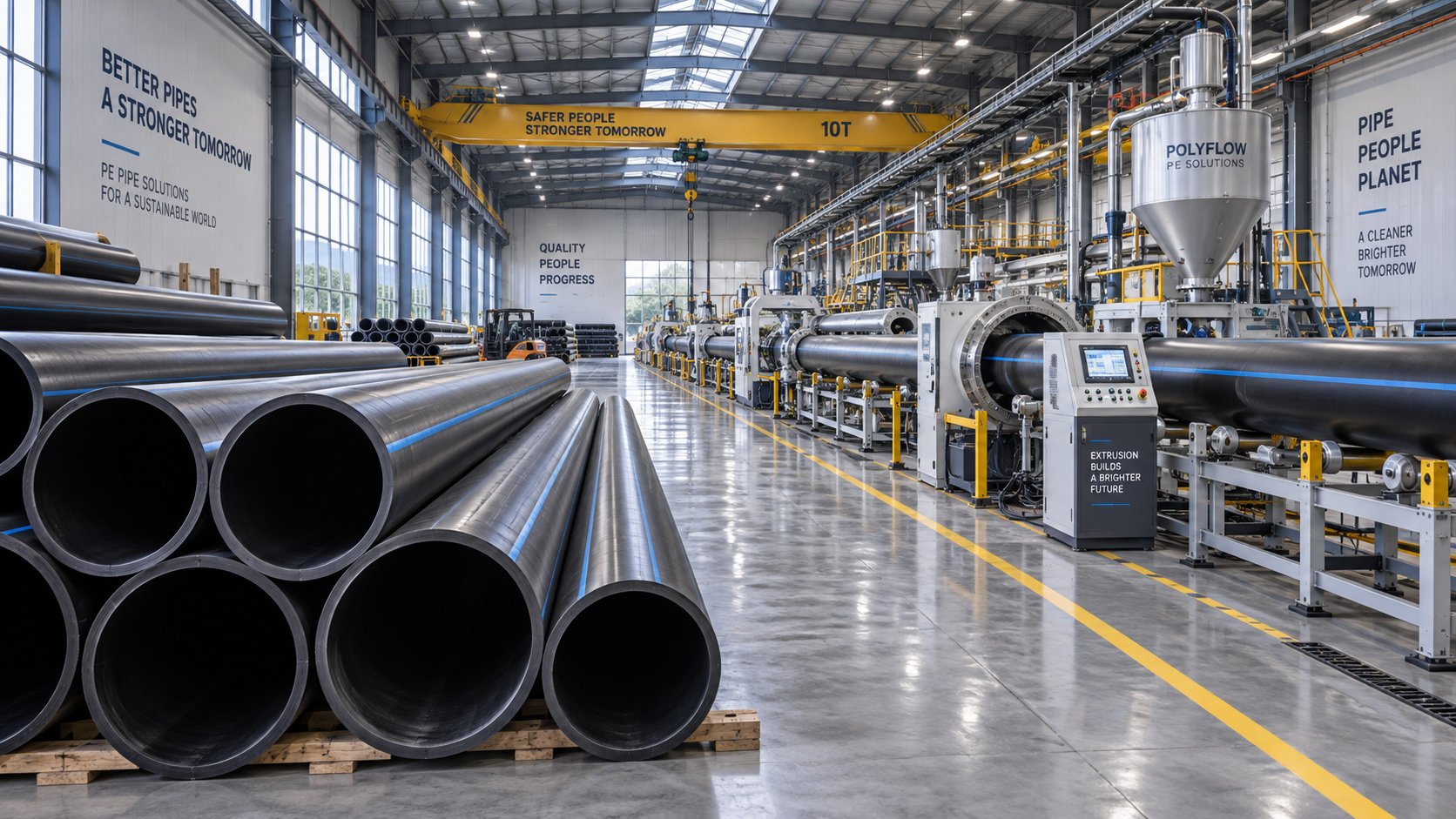
Factory Planning and Future-Ready Upgrades for PE Pipe Lines
Imagine this: you've selected the right PE pipe making machine, matched it to the correct resin grade, and your operators know how to troubleshoot every defect in the book. But the production line sits in a factory where the cooling tanks can't get enough water pressure, the ceiling is too low to stack finished pipes efficiently, and there's no room to add a co-extrusion system when your biggest customer asks for multi-layer pipe next year. The equipment is capable - the facility isn't.
Factory layout and infrastructure planning don't generate the same excitement as a new extruder or an advanced control system. But they determine whether that equipment performs at its potential or operates at a fraction of it. Getting the physical environment right from the start - and building in room for upgrades - protects your investment for years to come.
Factory Layout and Utility Planning for PE Pipe Lines
A PE pipe production line is fundamentally a linear process, and that shapes everything about the space it requires. Material enters at one end, and finished pipes emerge at the other - often 30 to 60 meters away, depending on pipe diameter and cooling requirements. Larger-diameter lines producing thick-walled pipes need longer cooling paths, which can push total line length well beyond 50 meters. Your factory floor must accommodate this full stretch in a straight line, with additional clearance at both ends for material handling.
Ceiling height is another dimension buyers frequently underestimate. Finished pipes - especially those in the 315 mm to 1200 mm range - need vertical clearance for stacking racks and overhead crane movement. A minimum clear height of 6 to 8 meters gives you the room to stack pipe bundles safely and operate lifting equipment without spatial constraints. For operations that coil smaller-diameter pipe, you'll need floor area for coiling machines and coil storage rather than overhead height, but the footprint requirement is equally significant.
Utility connections deserve the same upfront attention as floor space. Consider the key infrastructure requirements:
- Water supply for cooling tanks - Cooling is the single largest water consumer on the line. A recirculating chilled water system with adequate pump capacity, filtration, and a cooling tower or chiller unit is essential. Water temperature consistency directly affects pipe dimensional stability, so your cooling infrastructure isn't a place to cut corners.
- Compressed air - Pneumatic cutters, actuated valves, and certain pipe handling equipment all require clean, dry compressed air at stable pressure. Plan for a dedicated compressor with a receiver tank and air dryer sized to handle peak demand without pressure drops during cutting cycles.
- Electrical supply - The extruder motor, barrel heaters, haul-off drives, and auxiliary equipment collectively draw significant power. A 65 mm extruder line might require 80 to 120 kW of connected load; a 120 mm line can exceed 300 kW. Confirm that your facility's electrical service, transformer capacity, and distribution panels can handle the full connected load with headroom for future additions.
Beyond the production line itself, think about upstream and downstream workflow. Raw material storage - typically silos for bulk resin delivery or warehouse space for bagged pellets - should be located close to the extruder feed end to minimize material transport distances and contamination risk. On the output side, a finished pipe staging area large enough to hold several shifts' worth of production keeps the stacking system clear and prevents bottlenecks. As DRTS notes from decades of factory design experience, defining as many meaningful design inputs as possible at the pre-design stage is the single most effective way to ensure your facility operates efficiently from day one.
One layout detail worth flagging: leave physical space alongside the extrusion line for a second extruder position. Even if you're installing a single-layer line today, the floor space and utility provisions for a co-extrusion setup are far cheaper to build into the original layout than to retrofit later when walls, conduits, and cooling manifolds are already in place.
Modern Upgrades That Improve Output and Quality
A PE pipe extrusion line isn't a static investment. The equipment you install today can be progressively upgraded over its service life to improve throughput, tighten tolerances, reduce material waste, and expand product capability. The key is knowing which upgrades deliver the highest return and prioritizing accordingly.
Servo-driven haul-offs replace conventional AC-drive haul-offs with closed-loop servo motors that maintain pulling speed within extremely tight tolerances. The result? Wall-thickness consistency improves measurably because speed fluctuations - a primary cause of longitudinal wall variation - are virtually eliminated. For operations producing pressure-rated pipe to standards like ISO 4427, this upgrade often pays for itself through reduced material overuse alone, since tighter dimensional control means you can target closer to the minimum wall thickness without risking out-of-spec readings.
Gravimetric dosing systems bring the same precision philosophy to material feeding. Instead of metering pellets by volume (where bulk density variations introduce flow inconsistencies), gravimetric feeders weigh material continuously and adjust feed rates in real time. Rollepaal's gravimetric control technology, for example, uses load-cell-equipped hoppers to monitor material flow directly, enabling automatic adjustment of downstream line speeds to maintain consistent output. The practical benefit is straightforward: less material waste, more consistent pipe weight per meter, and reduced variability across production runs.
Multi-layer co-extrusion capability opens entirely new product possibilities without replacing your primary line. Adding a secondary extruder and a co-extrusion die head allows you to produce pipes with colored outer skins for product identification, recycled PE core layers that reduce raw material costs, or specialized barrier layers for chemical resistance. This is the upgrade that transforms a single-product line into a versatile manufacturing platform.
Inline ultrasonic wall thickness measurement provides continuous, non-contact dimensional monitoring at multiple points around the pipe circumference. When integrated with the PLC control system, this data enables closed-loop feedback - the system automatically adjusts haul-off speed or extruder output to correct dimensional drift before it produces out-of-spec pipe. The combination of inline measurement and automatic correction is one of the most impactful upgrades for PE pipe extrusion line efficiency, directly reducing scrap rates and material consumption.
There's one upgrade category that often gets overlooked but delivers outsized impact: replacing worn screw barrels with high-performance alternatives. After thousands of operating hours, the original screw and barrel wear beyond optimal tolerances - pumping efficiency drops, melt homogeneity degrades, and defect rates creep upward. Rather than simply replacing them with identical components, this is an opportunity to upgrade. Bimetallic barrel linings extend wear life significantly. Optimized screw geometries - tailored to your specific resin grades and output requirements - can improve plasticization quality and increase throughput from the same extruder frame. Suppliers like NANHAIYA specialize in custom and replacement single screw barrels engineered for pipe extrusion applications, offering solutions optimized for different PE grades and processing conditions. Sourcing these critical wear components from a specialized manufacturer rather than relying solely on OEM parts gives you access to upgraded materials and geometries that can meaningfully extend line uptime and improve melt quality - often at competitive lead times and pricing.
Planning for Future Capacity and Flexibility
The PE pipe market doesn't stand still. Municipal infrastructure programs expand. New standards emerge. Customers who ordered only 110 mm water pipe last year suddenly need 315 mm and 630 mm for a major project. A future-ready PE pipe production line setup anticipates these shifts rather than reacting to them.
When specifying new equipment or planning facility upgrades, prioritize flexibility and scalability. Choose lines that accommodate a wide diameter range through interchangeable die sets rather than being locked to a narrow size window. Select control systems with recipe storage and data logging capabilities that scale with your product catalog. Design your factory layout with physical and utility provisions for additional equipment - a second extruder, an inline measurement station, an automated coiling system - even if those additions are years away.
Here are the key upgrade priorities ranked by their typical impact on production efficiency:
- Inline wall thickness measurement with closed-loop control - Delivers the most immediate and measurable improvement in both dimensional accuracy and material savings; reduces scrap and enables tighter specification targeting
- Gravimetric dosing system - Eliminates feed-rate variability, stabilizes extruder output, and provides weight-per-meter tracking for quality documentation
- Servo-driven haul-off upgrade - Improves wall-thickness consistency along the pipe length; particularly impactful for thin-walled, high-speed production
- High-performance replacement screw barrel - Restores or exceeds original melt quality and throughput; often the most cost-effective way to rejuvenate an aging extruder without replacing the entire machine
- Multi-layer co-extrusion head and secondary extruder - Expands product capability into striped, skinned, or barrier-layer pipes; highest capital cost but broadens market reach significantly
- IoT-enabled remote monitoring and data logging - Enhances visibility, supports predictive maintenance, and provides quality traceability records required by an increasing number of end-use specifications
A PE pipe making machine is a long-horizon investment - often running productively for 15 to 20 years or more with proper maintenance and periodic upgrades. The factories that get the most value from that investment are the ones designed with tomorrow's requirements in mind, not just today's order book. Floor space that accommodates growth, utility systems with spare capacity, control platforms that accept new modules, and a supply chain for critical wear parts that isn't dependent on a single source - these are the decisions that compound in value year after year, turning a production line purchase into a lasting competitive advantage.
Frequently Asked Questions About PE Pipe Making Machines
1. What components are included in a PE pipe making machine?
A PE pipe making machine is a complete production line consisting of several synchronized units: a single-screw extruder with a screw and barrel that melts polyethylene resin, an annular die head that shapes the melt into a hollow tube, a vacuum sizing tank with calibration sleeves that locks in the pipe's outer diameter and roundness, spray or immersion cooling tanks for full solidification, a caterpillar or belt-type haul-off unit that pulls the pipe at constant speed, a planetary or chipless cutting station, and a pipe stacker or coiler. Each component must work in precise coordination - the extruder's output rate, haul-off speed, and cutter timing are all interdependent. The screw and barrel are considered the most critical wear components, and sourcing high-quality replacements from specialized manufacturers like NANHAIYA (nhyscrews.com) can significantly extend line uptime and maintain melt quality over thousands of operating hours.
2. What is the difference between solid-wall and corrugated PE pipe extrusion lines?
Solid-wall PE pipe lines produce smooth, uniform-wall pipes designed for pressure applications such as municipal water supply and gas distribution, typically covering diameters from 16 mm to over 1600 mm. They use a standard annular extrusion die and vacuum calibration sizing. Corrugated or structured-wall PE pipe lines, on the other hand, create pipes with engineered ribbed or hollow profiles that deliver high ring stiffness at reduced weight. These lines use a corrugator with moving mold blocks and often require dual extruders for double-wall construction. Structured-wall pipes target non-pressure, gravity-flow applications like stormwater drainage, sewage systems, and cable protection. The investment level, die tooling, and operational expertise differ substantially between the two configurations, so buyers must identify their target application before selecting a line type.
3. How do PE resin grades like PE80 and PE100 affect pipe machine settings?
PE resin grades directly influence multiple machine parameters across the extrusion line. PE100, with its higher minimum required strength (10.0 MPa vs 8.0 MPa for PE80) and lower melt flow index, demands higher barrel temperatures - typically 10 to 15 degrees C above PE80 settings - and generates greater melt pressure due to its higher viscosity. This means the extruder motor works harder, and screw design must accommodate the thicker melt. PE100 also enables thinner pipe walls at the same pressure rating, which changes die gap settings, reduces cooling time requirements, and may allow faster haul-off speeds. PE-RT grades for hot water applications require a low-temperature, low-shear processing philosophy to preserve their elevated-temperature performance. Operators should always consult resin supplier datasheets and run trial extrusions when switching between grades to establish optimal parameter sets.
4. What pipe diameter range can a PE pipe making machine produce?
PE pipe making machines cover an extensive diameter range from 16 mm up to 1600 mm or more for solid-wall lines, and up to 3000 mm for specialized winding-type structured-wall systems. The achievable diameter depends primarily on the extruder screw size: a 45-65 mm screw handles 16-63 mm pipes at roughly 80-200 kg/h output, while a 120-150 mm screw produces 630-1200 mm+ pipes at 700-1600+ kg/h. Each diameter range requires matched die heads, calibration sleeves, cooling tank lengths, and haul-off capacity. Many manufacturers invest in multiple interchangeable die sets to cover their full product catalog, and choosing a line that supports quick die changeovers minimizes downtime when switching between pipe size families.
5. How do you troubleshoot uneven wall thickness in PE pipe extrusion?
壁厚不均是聚乙烯(PE)管材挤出中最常见且后果最严重的缺陷之一。其主要原因是模头未对准——当芯轴未精确位于外模环中心时,更多的材料会通过较大的间隙流入,导致一侧壁厚增加。为了纠正这一问题,操作人员会调整模头周围的定心螺栓,同时使用超声波壁厚仪在多个圆周位置进行实时测量。其他影响因素包括:磨损或错位的夹持轨道导致牵引张力不一致;定径槽内真空分布不均导致与校准套筒接触不均匀;以及冷却不对称,即管材一侧凝固速度快于另一侧。磨损的螺杆料筒也会造成熔体输送不均匀。解决壁厚问题通常需要同时检查多个工位,而不是仅仅假设存在单一的根本原因。
Written by
Nanhaiya Technical Team
Zhoushan Nanhaiya Plastic Machinery Co., Ltd.
The Nanhaiya technical team supports screw and barrel manufacturing projects through application review, technical communication, custom manufacturing coordination, and production and quality control.
Discuss Your Application
Related Articles
More insights on screw barrel technology and plastics processing.

Extruder Machine Decoded: From Raw Pellet To Finished Product
Oct 6, 2026
Learn how an extruder machine works, compare single-screw vs. twin-screw types, and get expert guidance on specs, troubleshooting, and selection.
Read Article
PVC Profile Making Machine Decoded: From Raw Resin To Profit
Oct 3, 2026
Learn how a PVC profile making machine works — extrusion process steps, key technical parameters, die design, calibration methods, maintenance, and total cost of ownership.
Read Article
Blown Film Extrusion Machine Decoded: From Resin to Finished Roll
Sep 28, 2026
Learn how a blown film extrusion machine works — components, process parameters, BUR calculations, multi-layer setups, resin compatibility, and maintenance tips.
Read ArticleLooking for something else?
Search by material, symptom or product and jump straight to the relevant page.
These are navigation suggestions based on keyword matching — not a quotation, not a delivery commitment, and not a substitute for engineering review. Final specification is confirmed by our engineers against your drawings and processed material.
Need help with screw barrel selection?
Share your machine model, processed material and application. Our team can help with pricing and technical support.