


什么是PVC型材制造机?它为何如此重要?
想象一下,一个生产系统能够将粉末状PVC树脂熔化、成型、冷却,并输出最终成品窗框或电缆槽——所有工序均在一个连续的流程中完成。这就是PVC板材成型机的工作原理。然而,这个名称可能会产生错误。台独立的设备,而是一条集成的交叉生产线,由多个同步运行的单元组成,包括交叉机、精密模头、布局台、冷却槽、牵引单元和自动切割机。每个单元都快速依次执行不同的任务,从而生产出尺寸精度极高的连续PVC板材。
对于评估生产设备的制造商、工程师和采购团队而言,了解这些组件之间的对应是明智投资与盲目购买之间的关键区别。本指南从调查中立的角度,详细讲解了PVC型材缺陷工艺的每个阶段、重要的技术参数、预期成本以及保护投资的维护措施。
PVC型材制造机是什么?
PVC型材挤出机是一种工业生产线,它通过一种称为挤出的热机械,将干混PVC化合物连续成型为各种型材。原材料进入加热料筒,旋转的螺杆化合物将熔化并均质化,将其挤压通过特制的然后模头。是窗框、踢脚板还是槽线——都会经过真空布局、水冷、以可控速度拉伸,并切割成所需长度。由于每个下游单元都必须与后续机的输出速度匹配准确,因此整条生产线作为一个协调的整体系统运行,而不是一系列独立机器的集合。
为什么PVC型材在现代建筑中主导主导地位
PVC在建筑行业的地位主导并非偶然。硬质PVC型材具有耐腐蚀、抗磨损和防潮的特性,这些特性直接转化为更长的使用寿命和风机的维护成本,适用于窗框、门系统和外墙覆层。此外,PVC的重量也远轻于铝或木材,从而降低了运输和安装成本。再加上其可恢复性,很难理解为什么建筑行业占全球PVC总消费量的50%以上,而且预计到2035年,全球PVC市场将增长4.30%的复合年。
预计到 2035 年,PVC 的建筑和施工终端用途领域将以 5.1% 的复合年增长率增长,这主要得益于亚太地区的住宅建设、中东的基础设施发展以及欧洲各地的翻新工程——这使得可靠的型材挤出设备比以往任何时候都更加重要。
这些材料优势造就了对高品质PVC型材的持续、不可或缺的需求。对于任何希望满足这一需求的制造商而言,出发点始终如一:了解支撑生产的设备。而这首先要了解有哪些型材类型,每种类型对机器的要求,以及不同的生产线配置如何影响产品质量。
PVC型材的类型及其所需的机器配置
这里有一个大多数设备指南完全忽略的细节:您应该根据想要生产的型材来选择机器,而不是反过来。多腔窗框和简单的电缆管道都是硬质PVC产品,但它们对模头设计、挤出机产能和下游设备的要求却截然不同。选择错误的配置会导致尺寸不稳定、废料过多,或者生产线无法达到实际配方所标称的产量。了解型材类型与PVC型材生产机器类型之间的关系,是做出明智购买决策的第一步。
常见PVC型材类别及应用
PVC型材的截面复杂程度差异惊人。一方面,窗框和门框采用多腔室设计,内壁薄,转角半径小,尺寸公差严格,这些都直接影响隔热性能和结构完整性。这类型材通常需要共挤软密封条或抗紫外线盖层,进一步增加了产品的复杂性。
At the other end sit cable trunking and conduit channels. These are relatively simple, open-or-closed rectangular sections with fewer dimensional constraints. Between these two extremes lie skirting boards, ceiling panels, decorative trims, and industrial channels — each with its own cross-sectional geometry, surface finish requirements, and weight-per-meter targets.
What makes this important? Every added internal chamber, every co-extruded layer, and every tight tolerance tightens the demands on your plastic profile manufacturing extruders, die engineering, and calibration setup. A line perfectly suited for flat ceiling panels may struggle to hold shape on a six-chamber window profile — and vice versa.
Matching Machine Configuration to Profile Type
Different profiles demand different answers to the same core questions: how much melt volume is needed, how complex must the die's flow channels be, how aggressively must the calibration unit hold shape, and how fast can the line realistically run?
A pvc window profile extrusion machine, for instance, typically requires a larger conical twin-screw extruder — often an SJZ80/156 or SJZ92/188 — paired with a multi-zone precision die capable of distributing melt evenly across complex internal chambers. Vacuum calibration is essential because negative pressure pulls the soft extrudate firmly against a precision sizing sleeve, locking in chamber geometry before the PVC fully solidifies. Co-extrusion capability adds a secondary extruder to apply soft-lip seals or colored cap layers in a single pass.
A pvc cable trunking extrusion line, by contrast, can often run on a smaller SJZ65/132 conical twin-screw setup with a simpler single-channel die. Calibration demands are lighter, and line speeds can be higher because the profile's cross-section is less intricate.
The table below maps five common profile types against their key machine configuration requirements, giving you a practical framework for matching product goals to equipment specifications.
| Profile Type | Extruder Type & Typical Model | Die Complexity | Calibration Method | Typical Output Rate |
|---|---|---|---|---|
| Window & Door Frames | Conical twin screw (SJZ80/156 or SJZ92/188); co-extrusion extruder often required | High — multi-chamber flow channels with internal mandrels | Vacuum calibration with multi-zone sizing sleeves | 250 – 650 kg/h |
| Cable Trunking & Conduit | Conical twin screw (SJZ65/132) | Low to moderate — single open or closed rectangular section | Vacuum or spray calibration | 150 – 300 kg/h |
| Ceiling & Wall Panels | Conical twin screw (SJZ80/156); high-speed line variants available | Moderate — wide, flat cross-section with possible hollow cores | Vacuum calibration with extended cooling table | 250 – 400 kg/h |
| Skirting Boards & Decorative Trims | Conical twin screw (SJZ65/132 or SJZ80/156) | Moderate — visible surface finish and embossing requirements | Vacuum calibration; lamination or embossing unit may be added | 150 – 300 kg/h |
| Industrial Channels & Technical Profiles | Conical twin screw (SJZ65/132 to SJZ80/156, depending on size) | Variable — custom cross-sections with tight tolerances | Vacuum calibration with profile-specific sizing fixtures | 150 – 400 kg/h |
Notice a pattern? Conical twin-screw extruders dominate across nearly every category. Their geometry delivers stable melt pressure and gentle plasticizing — critical for heat-sensitive rigid PVC. The real differentiation happens downstream: in the die, the calibration table, and any co-extrusion or surface-finishing units appended to the line.
This means the first conversation with any equipment supplier should start with your finished product — dimensioned drawings, wall thicknesses, chamber counts, surface requirements, and target output in both kilograms per hour and meters per minute. As one industry buyer's guide puts it, a high kg/h figure has limited value if the cooling section cannot stabilize the profile at the required line speed. Getting the configuration right from the start is what separates a profitable line from an expensive lesson.
Of course, matching the right machine to the right profile is only half the equation. The other half is understanding what happens inside that machine — step by step, from the moment raw PVC powder enters the hopper to the second a finished profile drops onto the stacker.
The Complete PVC Profile Extrusion Process Step by Step
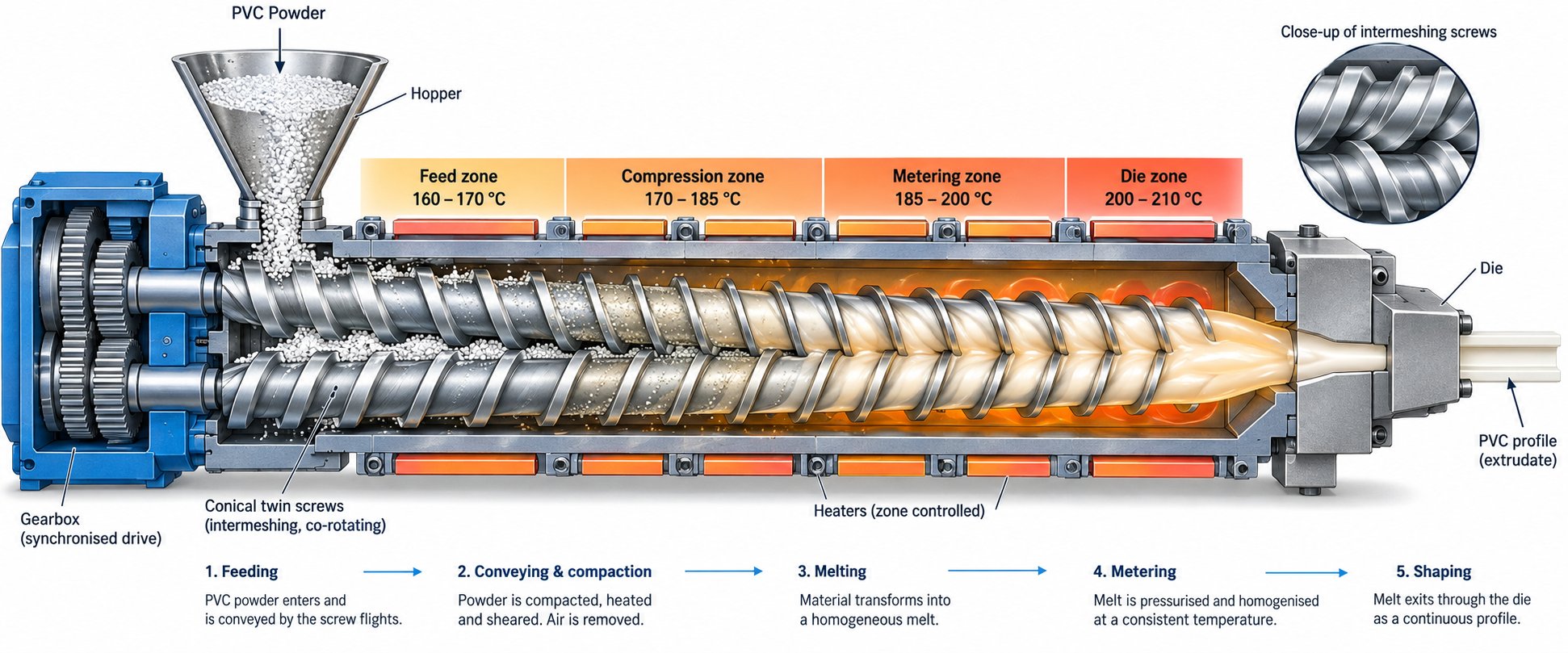
Every finished PVC profile — whether it is a multi-chamber window frame or a simple skirting board — passes through the same fundamental sequence of pvc profile extrusion process steps. Skip or mismanage any single stage, and the defect cascades downstream. A rough dry blend starves the extruder. An uneven melt warps in the die. A poorly calibrated profile fails dimensional inspection. Understanding the full chain from powder to packaged product is what separates operators who troubleshoot quickly from those who chase problems for hours.
Here is the entire process, broken into its core stages:
- Raw material preparation and dry blending — PVC resin is weighed and combined with additives in a high-speed mixer, then cooled and stored.
- Feeding — The dry blend is conveyed into the extruder hopper via a controlled feeding system.
- Plasticizing and melting — Rotating screws compress, shear, and heat the compound into a homogeneous melt inside the barrel.
- Die shaping — Molten PVC is forced through a precision-machined die to form the desired cross-section.
- Vacuum calibration — The still-soft extrudate is pulled against a sizing sleeve under negative pressure to lock in dimensions.
- Cooling — The profile passes through a water tank to reach room temperature gradually, preventing internal stress.
- Haul-off — A gripper unit pulls the cooled profile forward at a speed synchronized with extruder output.
- Cutting and stacking — An automatic saw cuts profiles to specified lengths, and a stacker or tilting table collects them.
Each of these stages deserves a closer look.
Raw Material Preparation and Dry Blending
PVC extrusion raw material preparation is where product quality is actually born — long before the extruder even starts. PVC resin powder on its own is thermally unstable and nearly impossible to process. It must be blended with a precise recipe of additives: heat stabilizers (such as calcium-zinc or tin-based systems) to prevent degradation, impact modifiers like CPE or ACR for toughness, acrylic-based processing aids to improve melt flow and surface finish, internal and external lubricants (stearic acid, paraffin wax) to reduce friction, calcium carbonate fillers to manage cost and rigidity, and titanium dioxide for whiteness and UV resistance.
These ingredients are loaded into a high-speed mixer that spins at several hundred RPM. Frictional heat raises the batch temperature to around 110-120°C, allowing the resin particles to absorb the liquid and powdered additives. The result is a free-flowing "dry blend" — not yet melted, but uniformly coated and ready for extrusion. The hot blend then transfers to a cooling mixer, which brings it down to a safe storage temperature below 40°C.
Why does this matter so much for downstream equipment? Because an inconsistent blend — clumps of undispersed stabilizer, uneven lubricant distribution, or moisture contamination — directly translates into erratic melt behavior inside the extruder. You'll see fluctuating motor current, pressure spikes at the die, and surface defects on the finished profile. The formulation is, in many ways, the invisible blueprint that the entire pvc profile extrusion line follows.
From Feeding to Extrusion Through the Die
The dry blend travels from storage silos into the extruder hopper through either a volumetric or gravimetric feeding system. Volumetric feeders deliver material at a set screw speed — simple and affordable, but sensitive to changes in bulk density. Gravimetric feeders continuously weigh the material and adjust feed rate in real time, delivering more consistent throughput. For profile extrusion plastic applications with tight weight-per-meter tolerances, gravimetric feeding is the more reliable choice.
Inside the barrel, a pair of counter-rotating conical twin screws takes over. As the compound moves along the screws, it passes through several functional zones. In the feed zone, the large-diameter end of the conical screws pulls material in efficiently due to the wide flight volume. As the screws taper toward the discharge end, the decreasing channel depth compresses the powder, squeezing out trapped air.
Simultaneously, barrel heaters — arranged in multiple independently controlled temperature zones — raise the compound temperature progressively, typically from around 160°C near the feed throat to approximately 190°C approaching the die. The combination of shear from screw rotation and conducted heat from the barrel transforms the dry powder into a smooth, viscous melt. Screw geometry plays a decisive role here: the compression ratio, flight depth, and pitch determine how aggressively the material is sheared. Too much shear generates excessive frictional heat, risking thermal degradation of the heat-sensitive PVC. Too little leaves unmelted particles that show up as specks or weak spots in the finished profile.
At the barrel's end, the homogeneous melt is pushed under pressure through a precision-machined steel die. This die contains flow channels carefully shaped to distribute the melt evenly across the profile's entire cross-section. For a simple rectangular trunking, the die might have a single straightforward channel. For a multi-chamber window frame, the die incorporates internal mandrels and flow dividers that split and recombine the melt stream to form hollow chambers and thin internal walls — all while maintaining uniform wall thickness throughout.
Calibration, Cooling, Haul-Off, and Cutting
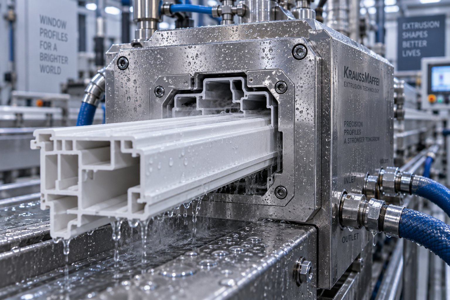
The profile emerging from the die is geometrically correct in shape but still soft and hot — roughly 180°C at the surface. Without immediate dimensional control, gravity alone would distort it. This is where vacuum calibration steps in. The soft extrudate enters a water-cooled stainless steel sizing sleeve connected to a vacuum pump. Negative pressure inside the sleeve pulls the profile's outer surface firmly against the precision-machined interior walls, locking in the exact cross-sectional dimensions as the PVC begins to solidify. For complex profiles, multiple calibration stages with independently adjustable vacuum zones may be used to control each section of the geometry.
After calibration, the profile passes through a series of water-cooling tanks — sometimes several meters long — where spray or immersion cooling gradually brings it to room temperature. Gradual cooling is critical. Rapid, uneven cooling creates internal stresses that can cause warping, bowing, or dimensional changes after the profile leaves the line.
A haul-off unit, typically using rubber-padded caterpillar tracks or belt grippers, pulls the cooled profile forward at a precisely controlled speed. This speed must be tightly synchronized with the extruder's output rate. If the haul-off pulls too fast, the profile stretches and wall thickness drops below specification. Too slow, and the profile thickens and may buckle between the die and the haul-off. Closed-loop speed control between the extruder drive and the haul-off motor keeps this balance stable.
Finally, an automatic cutting unit — usually a planetary saw for clean, dust-minimized cuts — trims the continuous profile into specified lengths, commonly 3 m, 4 m, or 6 m depending on the application. A stacker or tilting table collects the cut pieces, and they move on to inspection, optional post-processing such as lamination or protective film application, and packaging.
Every one of these stages involves specific machine parameters — temperatures, pressures, speeds, and tolerances — that interact with each other. Changing one setting ripples through the entire line. That interdependence is precisely why understanding the technical parameters behind each component is so valuable, especially when reading equipment specification sheets or evaluating supplier proposals.
Key Technical Parameters and What They Actually Mean
Equipment catalogs and supplier quotations for a PVC profile extruder are packed with numbers — L/D ratios, compression ratios, motor kilowatts, heating zone counts. Yet most spec sheets assume you already know what these figures mean in practice. If you have ever stared at a datasheet and wondered whether a 25:1 ratio is better than a 20:1, or what screw speed RPM actually tells you about production capacity, this section is for you. Treating pvc extrusion machine technical parameters as a foreign language puts buyers at a serious disadvantage during supplier negotiations. Treating them as practical decision-making tools changes the conversation entirely.
Essential Technical Terms Every Buyer Should Know
Below is a structured glossary of the parameters you will encounter most frequently when evaluating any pvc profile extrusion machine. Each term is paired with its real-world significance so you can move from reading numbers to understanding performance.
| Term | Definition | Typical Range (PVC Profile Extrusion) | Why It Matters |
|---|---|---|---|
| L/D Ratio (Length-to-Diameter) | The ratio of the screw's effective flighted length to its diameter. A profile extruder L/D ratio explained simply: it describes how much working length the material experiences inside the barrel. | 20:1 – 25:1 for conical twin screws; 24:1 – 36:1 for parallel twin and single screws | A higher L/D provides more residence time for melting, mixing, and homogenizing the PVC compound. As extrusion specialist Allan Griff notes, more length may mean more output if heating, melting, or mixing are the output limits. Too short an L/D can leave partially unmelted particles in the extrudate. |
| Compression Ratio | The ratio of the volume of the first screw flight to the volume of the last flight. In constant-pitch screws, it is often approximated as the ratio of feed-zone channel depth to metering-zone channel depth. | 2.0:1 – 4.0:1 | Determines how aggressively the material is compacted and air is expelled. A ratio that is too low allows trapped air to reach the die, causing bubbles. Too high generates excessive shear heat, risking PVC thermal degradation. |
| Screw Speed (RPM) | The rotational speed of the extruder screw, expressed in revolutions per minute. | 5 – 35 RPM for conical twin screws processing rigid PVC | Higher RPM increases throughput but also increases shear heating. Rigid PVC is heat-sensitive, so running too fast can cause discoloration or degradation. The optimal RPM balances output rate against melt quality. |
| Melt Pressure | The pressure of the molten PVC at the screw tip or die entrance, measured in MPa or bar. | 10 – 35 MPa at the die head | Indicates the resistance the melt faces entering the die. Excessively high pressure signals a blockage, contaminated screen pack, or improperly sized die. Consistent pressure means consistent profile dimensions. |
| Die Swell | The expansion of the extrudate as it exits the die and is no longer confined by the flow channel walls. | 5% – 15% expansion over die opening dimensions (varies by formulation) | Die swell must be anticipated during die design — the die opening is intentionally undersized to compensate. If swell is ignored, the finished profile will be oversized and out of tolerance. |
| Haul-Off Speed | The linear pulling speed of the downstream haul-off unit, expressed in meters per minute. | 0.5 – 6 m/min, depending on profile complexity and wall thickness | Must be precisely synchronized with extruder output. Too fast stretches the profile and reduces wall thickness. Too slow causes buckling or material buildup at the die exit. |
| Vacuum Calibration Pressure | The negative pressure applied inside the calibration sleeve to pull the soft extrudate against the sizing walls. | -0.02 to -0.08 MPa (partial vacuum) | Controls dimensional accuracy and surface finish. Insufficient vacuum allows the profile to sag or shrink away from the sleeve. Excessive vacuum can deform thin walls or create drag marks. |
Sounds like a lot to track? In daily operation, most of these parameters are monitored through the extruder's PLC control panel. The real value of understanding them shows up before you buy — when you are comparing quotations and need to judge whether a machine's specifications actually match your production goals.
How to Read a PVC Profile Extruder Specification Sheet
A typical spec sheet for a pvc profile extruder lists a dense grid of numbers. Here is how to translate the most important ones into practical production capability.
Screw diameter is your starting point. For conical twin-screw machines, you will see it written as two numbers — for example, SJZ65/132. The first number (65 mm) is the small-end diameter at the discharge, and the second (132 mm) is the large-end diameter at the feed. Bigger diameters accommodate higher throughput and wider process windows, but they also require more powerful drives and consume more energy. Match screw size to your target output rate, not to the largest available option.
Motor power, listed in kilowatts (kW), tells you how much torque the drive can deliver to the screws. A 37 kW motor on an SJZ65/132 is standard for cable trunking and light profiles. Window frame lines running SJZ80/156 or SJZ92/188 extruders typically need 55 kW to 110 kW. Undersized motors limit your maximum throughput and may overheat under sustained full-load operation.
Output capacity appears in kilograms per hour (kg/h). Treat this number cautiously — it is usually quoted at optimal conditions with a specific formulation. Your actual output depends on the profile's cross-sectional complexity, your PVC formulation's melt behavior, and how fast the downstream cooling section can stabilize the product. Always ask the supplier which profile geometry and line speed the quoted output assumes.
Heating zone count indicates how many independently controlled temperature zones the barrel offers. More zones — commonly four to six on a conical twin-screw barrel — give you finer control over the temperature gradient from feed to discharge. This matters because rigid PVC requires a carefully staged temperature ramp. Too few zones force compromises: you might achieve the correct melt temperature at the die but overheat the feed section, leading to premature gelation and inconsistent flow.
Reading a spec sheet this way — connecting each parameter to a real production outcome — transforms the document from a marketing brochure into a decision-making tool. And it prepares you for the next critical layer of understanding: how the die and the calibration unit downstream of the extruder actually determine whether that melt becomes a saleable profile or scrap.
Die Design and Calibration Units That Define Profile Quality
Every parameter discussed so far — screw geometry, motor power, barrel temperature zones — feeds toward a single moment: the instant molten PVC exits the die and enters the calibration unit. These two components, sitting at the physical junction between the extruder and the downstream line, have an outsized influence on whether your finished profile meets specification or ends up as regrind. Yet die design principles and calibration methods are rarely explained in equipment guides. Most suppliers show you the extruder and quote throughput numbers, while the die and calibration table — the components that actually shape and freeze your product — get a footnote at best.
That gap matters. A perfectly plasticized melt pushed through a poorly designed die produces a defective profile. A well-shaped extrudate entering a mismatched calibration unit loses its geometry within seconds. Understanding how these two systems work — and how they interact — gives you a sharper eye when evaluating any plastic profile extrusion machine.
Die Design Principles for Accurate Profile Cross-Sections
Think of the extrusion die as a translator. It receives a cylindrical stream of homogeneous melt from the extruder and reshapes it into a completely different cross-section — perhaps a six-chamber window frame with walls as thin as 1.5 mm. That translation depends entirely on the internal flow channel geometry, and getting it right is part engineering science, part iterative refinement.
Several core pvc extrusion die design principles govern whether the finished profile matches the intended shape:
Flow channel layout. Inside the die, the melt stream must split from a single circular entry into the exact shape of the target profile. Flow channels guide and redistribute the material so that every part of the cross-section — thick walls, thin walls, corners, and hollow chambers — receives a proportional share of melt at a uniform velocity. When flow balance is engineered correctly, the profile exits with consistent wall thickness and minimal internal stress. When flow paths are uneven, some sections receive too much material and bulge outward, while starved sections run thin and may collapse during cooling.
Land length. The land is the final parallel section of the flow channel just before the die exit. Its length determines how long the melt is confined in its final shape before emerging into open air. Longer land lengths stabilize the melt, reduce die swell, and improve dimensional consistency — but they also increase back pressure and can raise melt temperature through additional shear. Shorter lands allow higher throughput but make the profile more sensitive to pressure fluctuations. Choosing the right land length is a balancing act that depends on the profile's complexity and the PVC formulation's melt behavior.
Die lip adjustment. Most production dies include adjustable lip bolts or choke bars at the exit. These allow operators to fine-tune the gap at different points around the profile, compensating for minor flow imbalances without disassembling and re-machining the die. Skilled operators use lip adjustments daily to correct small variations caused by batch-to-batch formulation differences or ambient temperature shifts.
Internal surface finish. The flow channels inside the die must be highly polished. Rough surfaces increase friction, create drag marks on the profile exterior, and encourage material buildup that degrades over time. As Northland Plastics notes, smooth flow paths help prevent marks and irregularities, and streamlined geometry reduces turbulence that leads to melt fracture — a surface defect that appears as a rough, sharkskin-like texture.
Transition geometry. The path from the round barrel exit to the complex profile shape should avoid abrupt direction changes. Sharp transitions create dead zones where PVC can stagnate, overheat, and degrade — producing brown or black specks in the final product. Gradual, streamlined transitions maintain uniform velocity and prevent thermal damage in heat-sensitive rigid PVC compounds.
Here is the practical takeaway: when you evaluate a supplier's die for your target profile, ask about flow simulation results, land length ratios, and how the die accommodates your specific formulation. A die designed for one PVC resin may not perform well with another. As reference material from polymer processing literature confirms, melt viscosity and melt strength must align with channel design for stable, repeatable extrusion.
Vacuum Calibration vs. Spray Calibration
The profile leaving the die is geometrically shaped but still soft — imagine squeezing toothpaste from a tube. Without immediate external support, gravity, residual melt pressure, and uneven cooling would distort it within seconds. Calibration is the process that locks in the profile's final dimensions, and it is arguably the most underappreciated factor in finished product quality.
Two primary methods dominate vacuum calibration pvc profile extrusion and spray-based cooling systems. Each has distinct strengths, and choosing the wrong one for your profile type can undermine everything the extruder and die achieved upstream.
Vacuum calibration draws the still-soft extrudate into a precision-machined stainless steel sizing sleeve. A vacuum pump creates negative pressure inside the sleeve — typically -0.02 to -0.08 MPa — pulling the profile's outer surfaces firmly against the sleeve walls. Chilled water circulates through or around the sleeve, cooling the PVC rapidly while the vacuum holds it in position. The result is tight dimensional control and a smooth, high-quality surface finish. For complex profiles with hollow chambers, multiple vacuum zones can be independently adjusted to control each section of the cross-section separately. Modern calibration systems use multi-stage vacuum setups to prevent warpage and maintain dimensional accuracy even at higher line speeds.
Spray calibration takes a gentler approach. Instead of pulling the profile against a rigid sleeve, water jets or spray nozzles cool the extrudate gradually as it passes through an open or semi-enclosed chamber. The profile is supported on rollers or guides rather than constrained inside a sleeve. Cooling is slower and more uniform, which reduces internal stress — but dimensional control is inherently less precise because the profile is not held against a fixed reference surface during solidification.
When should you use which? The table below compares the two methods across the factors that matter most in production.
| Factor | Vacuum Calibration | Spray Calibration |
|---|---|---|
| Dimensional Accuracy | High — profile is held against a precision sizing sleeve under negative pressure | Moderate — profile is cooled without rigid dimensional constraint |
| Surface Finish Quality | Excellent — smooth contact with polished sleeve produces a glossy, mark-free surface | Good — less contact pressure means fewer drag marks, but surface gloss may be lower |
| Suitable Profile Types | Complex profiles: multi-chamber window frames, door frames, technical profiles with tight tolerances | Simpler profiles: solid rods, thick-walled sections, profiles where internal stress reduction is prioritized over tight tolerances |
| Equipment Complexity | Higher — requires vacuum pump, precision-machined sleeves custom-made for each profile, and multi-zone pressure control | Lower — standard spray nozzles, support rollers, and water collection system |
| Tooling Cost | Higher — each new profile requires a custom sizing sleeve | Lower — spray chambers are more universal across profile geometries |
| Internal Stress in Finished Profile | Moderate — rapid surface cooling can create a temperature gradient between the outer skin and core | Lower — gradual, even cooling reduces temperature differentials and residual stress |
| Typical Line Speed Compatibility | Moderate to high — multi-stage vacuum setups support faster line speeds on complex profiles | Moderate — cooling rate limits how fast the profile can travel through the spray zone |
In practice, the vast majority of rigid PVC profile production lines use vacuum calibration. The reason is straightforward: window frames, door profiles, cable trunking, and ceiling panels all require tight dimensional tolerances and smooth surface finishes that spray systems cannot consistently deliver. Spray calibration finds its niche in thick-walled industrial profiles, certain rod-and-bar applications, or as a supplementary cooling stage after the primary vacuum calibrator.
A critical point many operators overlook: calibration tooling must be precisely aligned with the die exit. Even a small misalignment — a fraction of a millimeter — introduces asymmetric drag on the soft extrudate, causing bowing or twisting that persists through the entire downstream line. Field observations from PVC extrusion plants consistently identify cooling system imbalance and calibration table misalignment as leading causes of dimensional drift in continuous production.
Die design and calibration are where engineering intent meets physical reality. They transform a theoretical cross-section into a product you can measure, test, and sell. Yet both depend entirely on the quality of the melt they receive — which brings the focus back upstream to the one component responsible for creating that melt in the first place: the screw and barrel system.
The Screw and Barrel System Behind Reliable PVC Plasticizing
Strip away the control panels, the cooling tanks, and the downstream equipment, and you are left with the one component that defines whether a PVC profile extrusion line produces sellable product or expensive scrap: the screw and barrel assembly. Every kilogram of PVC compound that passes through the line is conveyed, compressed, melted, and homogenized by this single system. The die shapes the melt. The calibration unit freezes the shape. But the screw and barrel create the melt itself — and the quality of that melt determines everything that follows.
Think of it this way. You can install the most precisely engineered die on the market and pair it with a multi-zone vacuum calibration table, but if the melt arriving from the barrel is inconsistent — pockets of unmelted powder, uneven temperature, fluctuating pressure — no amount of downstream precision can rescue the finished profile. Surface defects, dimensional drift, and internal voids all trace back to what happens inside the barrel. That is why experienced operators and engineers treat the screw and barrel as the heart of any pvc profile extruder.
Why the Screw and Barrel Are the Heart of PVC Extrusion
Inside the barrel, the screw assembly performs four distinct functions simultaneously. First, it conveys the dry-blended PVC powder from the feed hopper into the processing zone. Second, it compresses the loose powder, squeezing out trapped air that would otherwise create voids in the finished product. Third, it generates and transfers heat — through a combination of barrel heaters and frictional shear — to melt the compound into a viscous fluid. Fourth, it homogenizes that fluid, ensuring uniform temperature, consistent viscosity, and even distribution of stabilizers, fillers, and pigments throughout the melt stream.
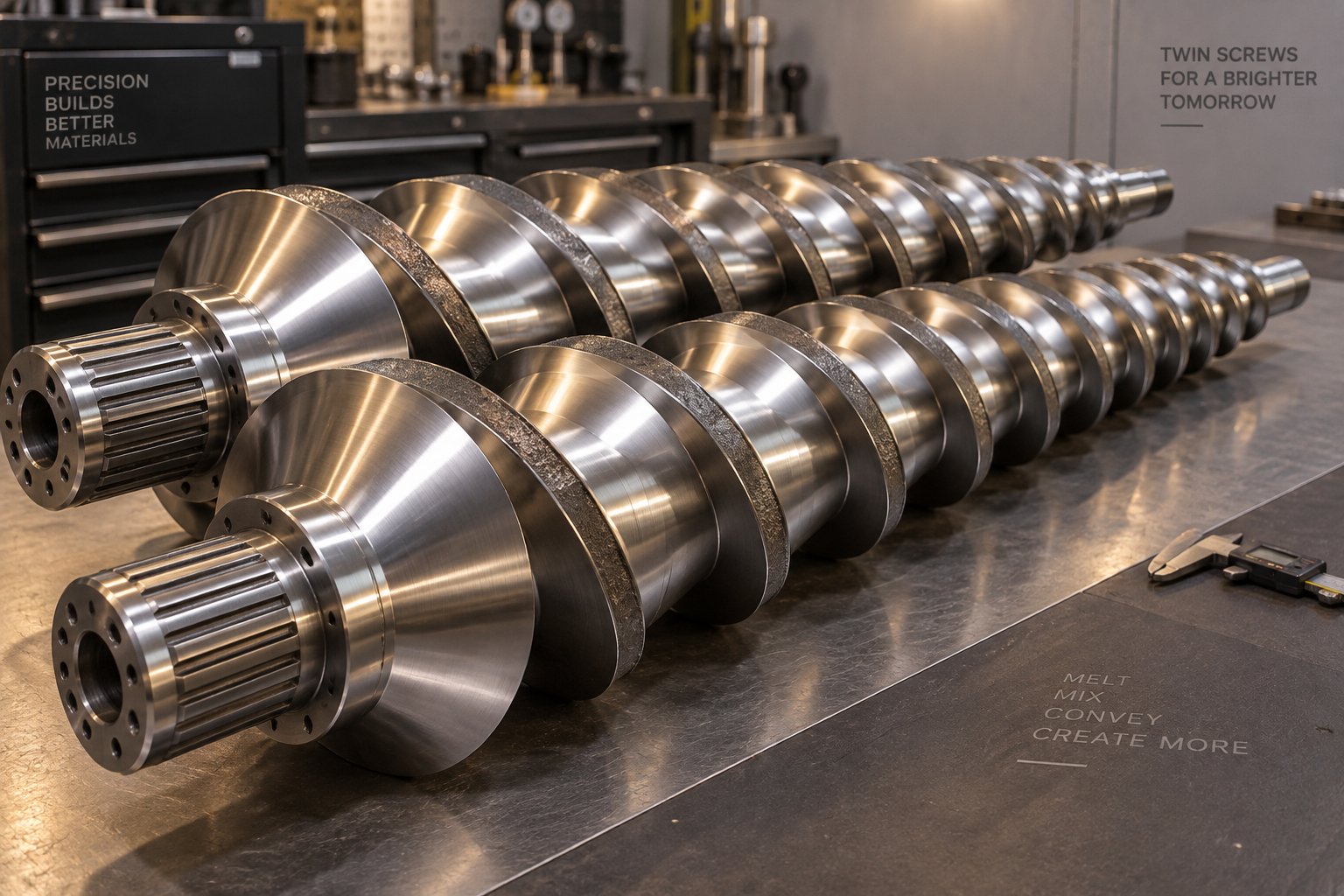
For rigid PVC profile extrusion, conical twin screw designs have become the industry standard — and for good reason. A conical twin screw barrel features two intermeshing, counter-rotating screws that taper from a large diameter at the feed end to a smaller diameter at the discharge. This geometry offers three critical advantages over parallel twin screws and single-screw alternatives:
High feeding efficiency. The large-diameter feed end provides generous flight volume, pulling in low-bulk-density PVC powder with minimal bridging or starving. As industry comparisons confirm, the conical design improves intake volume and pressure generation, which translates directly into stable throughput.
Gentle but thorough plasticizing. The gradual reduction in channel volume creates a progressive compression that melts PVC without subjecting it to the aggressive shear peaks found in high-speed parallel systems. Rigid PVC is notoriously heat-sensitive — its processing window between proper gelation and thermal degradation is narrow. The conical geometry keeps shear forces controlled and predictable, reducing the risk of discoloration or degradation. Research into conical twin screw barrel performance shows that energy consumption can drop by up to 30% compared to traditional barrel designs, precisely because the tapered profile distributes mechanical energy more efficiently.
Lower shear heat generation. Because conical twin screws operate at lower RPMs — typically 5 to 35 RPM versus several hundred for parallel systems — they generate less frictional heat. For a polymer that degrades if overheated by even a few degrees, this is not a minor convenience. It is a fundamental processing requirement.
The practical result? Pvc profile extruders built around conical twin screw systems deliver more stable melt pressure, more uniform melt temperature, and more consistent output weight per meter — the three metrics that matter most for dimensional accuracy and surface quality in finished profiles.
Yet none of these advantages are permanent. Screw and barrel wear is inevitable. Every hour of operation, abrasive fillers like calcium carbonate grind against the screw flights and barrel wall. Corrosive byproducts from PVC stabilizer decomposition attack metal surfaces. Over thousands of production hours, the clearance between screw flights and barrel bore gradually widens. When that happens, you will notice declining output volume as melt leaks backward through the enlarged gap. Energy consumption climbs because the motor works harder to maintain the same throughput. Melt temperature becomes inconsistent as the screw loses its ability to generate uniform shear. And surface defects on the finished profile begin appearing with increasing frequency. As one barrel engineering analysis explains, wear widens gaps between screw flights and barrel walls, leading to melt leakage, lower output, and uneven product quality.
Choosing the Right Conical Twin Screw Barrel for Stable Production
When wear reaches the point where process adjustments — lowering RPM, raising barrel temperatures, tightening die lip gaps — can no longer compensate, the screw and barrel need replacement. This is not a failure. It is a predictable maintenance event, much like replacing brake pads on a vehicle. The question is not whether it will happen, but whether you source a replacement component that restores your line to its original performance specification — or one that simply delays the next round of problems.
Several factors determine which conical twin screw barrel for PVC applications will deliver stable, long-term plasticizing performance:
Material composition. The barrel liner and screw surface treatment must resist both abrasion and corrosion. Bimetallic barrels — where a wear-resistant alloy is centrifugally cast onto the barrel bore — offer superior abrasion resistance compared to standard nitrided steel. Nitrided barrels provide adequate hardness for unfilled or lightly filled PVC formulations but wear faster when processing compounds loaded with calcium carbonate or other mineral fillers. For PVC profile, pipe, and WPC extrusion applications where filler content is moderate to high, bimetallic construction is typically the more durable choice.
L/D ratio compatibility. The replacement barrel's length-to-diameter ratio must match the extruder's original design. An SJZ65/132 has a different L/D than an SJZ80/156, and that ratio was engineered to deliver a specific residence time and compression profile for the target formulation. A mismatched L/D changes melt behavior in ways that cannot be corrected through process settings alone.
Compression ratio design. The screw's compression ratio — the volume ratio between the first and last flights — must suit your PVC formulation. Higher-filler compounds may need a more aggressive compression ratio to ensure complete air removal and uniform melt density. Softer formulations or foam board compounds may require a gentler ratio to avoid excessive shear.
Dimensional precision. Screw-to-barrel clearance is measured in hundredths of a millimeter. A replacement barrel machined to loose tolerances will leak melt from day one, negating the entire investment. Precision CNC machining and strict quality control during manufacturing are non-negotiable requirements for any component that sits at the core of your plasticizing system.
For PVC profile, pipe, board, foam board, and WPC extrusion manufacturers seeking a pvc extruder screw and barrel replacement that addresses these factors, NANHAIYA's conical twin screw barrel is purpose-built for exactly this application. Designed for custom and replacement installations, these barrels are engineered to restore stable plasticizing performance without requiring the manufacturer to replace the entire extruder — a practical and cost-effective approach to maintaining production continuity.
When evaluating any replacement conical twin screw barrel, use this checklist as your starting framework:
- Barrel material and liner type — Confirm whether bimetallic, nitrided, or chrome-plated construction is appropriate for your filler type and content level.
- Dimensional match — Verify exact screw diameter (both large and small end), barrel bore diameter, and overall length against the original equipment specification.
- L/D ratio and compression ratio — Ensure the replacement matches the extruder's engineered processing profile for your target PVC formulation.
- Surface treatment and hardness — Check barrel bore hardness (HV or HRC rating) and screw flight surface treatment to confirm they meet the wear demands of your compound.
- Manufacturer's machining tolerances — Request documented bore straightness, concentricity, and screw-to-barrel clearance specifications before ordering.
- Compatibility with existing drive and gearbox — Confirm spline dimensions, shaft length, and torque rating to avoid mechanical misfit during installation.
- Lead time and technical support — Evaluate whether the supplier offers formulation-specific guidance and timely delivery to minimize your production downtime.
Sourcing a precision-engineered replacement barrel is not an expense — it is an investment in sustained output quality and energy efficiency. A worn barrel that leaks melt, wastes energy, and produces off-spec profiles costs more per production hour than the replacement itself. Getting the selection criteria right the first time ensures your pvc profile extruders return to peak performance and stay there.
Of course, the screw and barrel are only one element of a much larger cost equation. The true financial picture of running a PVC profile production line extends far beyond the initial machine purchase — into energy consumption, raw material costs, spare parts cycles, and the often-overlooked impact of downtime on your bottom line.
Energy Efficiency and Total Cost of Ownership Explained
Ask any first-time buyer what a pvc profile production line costs, and you will almost certainly get a number that reflects one thing: the purchase price of the equipment. That figure matters, of course. But it represents a fraction — sometimes surprisingly small — of the total financial commitment. Manufacturers who budget only for the machine itself are often caught off guard by the ongoing operational expenses that accumulate month after month, year after year. A clear-eyed understanding of the pvc profile extrusion line cost means looking at the full lifecycle, not just the invoice.
Beyond the Purchase Price — Understanding Total Cost of Ownership
Total cost of ownership (TCO) captures every expense associated with acquiring, operating, and maintaining a production line over its useful life. For a PVC profile extrusion line, those expenses fall into several distinct categories, each carrying different weight depending on your scale, location, and product mix:
Machine acquisition is the most visible cost — the extruder, die, calibration table, cooling tank, haul-off, cutter, and control system. Depending on the line's size and automation level, this represents the single largest upfront expenditure but typically accounts for a smaller share of the ten-year total than most buyers expect.
Facility preparation and installation includes floor reinforcement, electrical infrastructure upgrades, water supply and drainage for cooling systems, ventilation, and the commissioning process itself. These site-readiness costs can add a meaningful percentage on top of the equipment price, especially for manufacturers setting up a new production facility rather than replacing an existing line.
Raw material procurement is the dominant recurring cost for most PVC profile operations. PVC resin, stabilizers, impact modifiers, fillers, and pigments are consumed continuously. Material efficiency — how many kilograms of sellable profile you produce per kilogram of compound fed into the extruder — has a direct and outsized effect on profitability. Lines equipped with gravimetric feeding and precise wall-thickness control minimize material giveaway, turning tighter process control into measurable cost savings.
Energy consumption covers electricity for extruder motors, barrel heaters, cooling water pumps, vacuum pumps, and auxiliary systems. This category often surprises operators. Over a five- to ten-year operating horizon, cumulative energy costs can rival or exceed the original machine purchase price — a reality that makes energy efficiency one of the most impactful levers for protecting operating margins.
Labor includes operators, maintenance technicians, and quality control staff. Higher levels of automation — centralized PLC control, automatic feeders, and self-correcting haul-off systems — reduce labor requirements per shift but increase the upfront equipment investment.
Routine maintenance and spare parts encompass scheduled replacements of wear items (screws, barrels, die inserts, heater bands, thermocouples, vacuum pump seals) plus unscheduled repairs. As covered in the previous chapter, worn screws and barrels alone can silently inflate energy consumption and scrap rates long before they trigger an obvious mechanical failure.
Downtime losses are the hidden cost multiplier. Every hour the line sits idle — whether for an unplanned repair, a slow spare-part delivery, or an extended die changeover — represents lost production revenue with fixed overhead still accumulating. Reliable equipment with accessible replacement components directly reduces this exposure.
The takeaway? A less expensive machine with higher energy draw, frequent maintenance intervals, and longer spare-part lead times can easily cost more over its lifetime than a pricier line engineered for efficiency and durability. Evaluating TCO rather than sticker price is what separates a sound capital decision from a regrettable one.
Energy Efficiency Factors That Impact Operating Margins
Energy deserves its own deeper look because it is the cost category where equipment design choices have the most measurable long-term impact — and where actionable pvc extrusion energy efficiency tips can deliver real savings without changing your product or formulation.
Three areas of machine design drive the bulk of energy consumption on a PVC profile line:
Motor and drive system. Older extrusion lines often use fixed-speed AC motors paired with mechanical gearboxes. These run at constant power draw regardless of actual load. Modern lines increasingly use AC inverter drives or direct-drive servo motors that match motor speed and torque to real-time demand. The difference is substantial — variable-frequency drives alone can reduce motor energy consumption significantly by eliminating the waste associated with throttling a fixed-speed motor. Coperion's modernization case studies report average energy savings of 8% to 14% from drive and process upgrades on existing extrusion systems.
Heating system design. Barrel heating accounts for a meaningful share of total line power draw. Standard ceramic band heaters are widely used but radiate a significant portion of their energy into the surrounding air rather than into the barrel wall. Infrared heaters and insulated barrel jackets improve thermal transfer efficiency, directing more energy into the PVC compound and less into the factory atmosphere. Even a simple measure like adding barrel insulation blankets to an existing line reduces heating energy demand and stabilizes barrel temperature zones. As Rollepaal's technical analysis notes, a well-designed PVC extrusion system uses mechanical energy from the screws to efficiently heat and homogenize the dry blend, reducing the need for excessive external heating and subsequent cooling.
Cooling system efficiency. Cooling towers, water pumps, and vacuum pumps run continuously during production. Oversized pumps operating at fixed speed waste energy. Variable-speed pump drives, optimized water flow routing, and properly maintained cooling towers reduce this baseline load. PVC itself is inherently efficient to process — requiring approximately three times less drive energy than polyolefins — with specific energy consumption around 100 Wh/kg at the extruder and 15 to 25 Wh/kg at the die. Capitalizing on this natural advantage depends on equipment that does not introduce unnecessary energy losses.
For operators looking to reduce energy costs on an existing or new pvc profile production line, the following strategies offer the highest return relative to their implementation effort:
- Install variable-frequency drives on the extruder main motor and all auxiliary motors (cooling pumps, vacuum pumps, haul-off drives) to match power consumption to actual load in real time.
- Add thermal insulation jackets to all barrel heating zones to reduce radiant heat loss and improve temperature stability.
- Optimize screw and barrel condition — worn components force the motor to work harder for the same output, quietly inflating energy consumption per kilogram of finished product.
- Use air cooling and closed internal screw cooling where process conditions allow, as these methods reduce maintenance requirements and energy consumption compared to traditional fluid-based cooling systems.
- Monitor specific energy consumption (Wh/kg) as a key performance indicator, tracking it weekly to catch efficiency drift early before it compounds into significant cost increases.
- Review and adjust screw configuration — even small changes to screw element arrangement or compression profile can reduce energy input while maintaining melt quality, as process optimization specialists have demonstrated across numerous modernization projects.
- Implement centralized process control with PLC-based monitoring that synchronizes extruder speed, haul-off speed, and cooling parameters to avoid overprocessing and energy waste during steady-state production.
None of these measures require replacing your entire line. Several — insulation blankets, VFD retrofits, specific energy tracking — can be implemented within days and begin delivering measurable savings immediately. The compounding effect of addressing multiple efficiency levers simultaneously is what transforms a marginally profitable operation into one with healthy, defensible margins.
Still, even the most energy-efficient line will encounter production problems. Surfaces go rough. Profiles bow. Colors shift. The difference between an hour of lost production and a full shift of downtime often comes down to one skill: the ability to diagnose an extrusion defect quickly and determine whether it requires a process adjustment or a component replacement.
Troubleshooting Common PVC Profile Extrusion Problems
A profile line running at steady state is a beautiful thing — consistent output, clean surfaces, tight dimensions. Then something changes. The surface turns rough. A slight bow appears. A faint yellow streak shows up on what should be a bright white frame. Every operator has been there, and the instinct is usually the same: start adjusting temperatures and speeds until the defect goes away. Sometimes that works. Sometimes it makes things worse. And sometimes the real problem is not a setting at all — it is a worn component quietly degrading your melt quality behind the scenes.
This pvc profile extrusion troubleshooting guide is designed to help you do two things quickly: identify the most likely cause of a defect based on its visible symptoms, and determine whether you can fix it through process adjustments or whether the line is telling you a component needs replacement.
Common PVC Profile Extrusion Defects and Their Causes
Most plastic extrusion profile defects fall into a surprisingly small number of categories. The challenge is not recognizing the defect — you can see roughness, warping, or discoloration with the naked eye. The challenge is tracing it back to the correct root cause when multiple variables are changing simultaneously. The table below maps six of the most frequent pvc extrusion defects and solutions, connecting each symptom to its likely origins and the machine-side corrections that address them.
| Defect | Visible Symptoms | Possible Causes | Recommended Machine-Related Solutions |
|---|---|---|---|
| Surface Roughness / Loss of Gloss | Dull, matte, or sandpaper-like surface texture instead of a smooth, glossy finish | Incomplete plasticization (melt too cold or screw speed too high); buildup of precipitates on die inner walls; insufficient vacuum pressure in the calibration sleeve; worn screw flights reducing melt homogeneity | Increase barrel temperatures in the feed and compression zones to improve melt uniformity; reduce screw speed to allow longer residence time; clean and polish die flow channels; raise vacuum calibration pressure to press the profile firmly against the sizing sleeve; inspect screw for wear |
| Uneven Wall Thickness | One side of the profile is thicker than the other, or internal chamber walls vary beyond tolerance | Unbalanced melt flow distribution in the die; misalignment between extruder, die, and calibration table; inconsistent haul-off grip pressure; worn or damaged die land | Adjust die lip bolts or choke bars to rebalance flow; use a laser level to verify centerline alignment across the entire line; check haul-off pads for uneven wear and replace if needed; have the die inspected and re-machined if land surfaces are scored |
| Warping or Bowing | Profile curves to one side or bows along its length after exiting the line | Uneven cooling — water spray reaching one side more than the other; die temperature imbalance causing asymmetric flow velocity; calibration table misalignment pulling the profile off-center; haul-off speed too high, preventing full solidification before stacking | Inspect and unclog cooling spray nozzles to ensure uniform water coverage on all sides; measure die face temperature at multiple points and adjust heater bands to equalize; realign calibration table using string or laser reference; reduce line speed to allow complete cooling before the profile exits the water tank |
| Burn Marks or Discoloration (Yellow/Black Lines) | Yellow streaks, brown spots, or black lines on the profile surface, especially on white or light-colored products | Degraded PVC trapped in die dead zones ("dead material"); barrel temperature too high in one or more zones; faulty thermocouple giving incorrect readings; inadequate thermal stabilizer in the formulation | Disassemble and thoroughly clean the die, polishing all internal flow channels to remove carbonized buildup; verify thermocouple accuracy with an external infrared thermometer and replace any faulty sensors; reduce barrel zone temperatures in 5-degree increments; review compound formulation with your material supplier |
| Die Lines (Longitudinal Streaks) | Continuous thin lines running along the length of the profile in the extrusion direction | Scratches or scoring on the die land or lip surface; metal particle contamination in the melt; plate-out (additive buildup) on the die exit face; partially blocked screen pack allowing unfiltered material through | Remove, inspect, and re-polish the die land; install or replace the breaker plate screen pack to catch metal particles; clean plate-out deposits from the die lip at regular intervals during production; check upstream barrel for signs of metallic wear debris from screw flights |
| Poor Dimensional Accuracy (Profile Out of Tolerance) | Finished profile dimensions do not match specification — cross-section too large, too small, or inconsistent along length | Incorrect vacuum calibration pressure; haul-off speed not synchronized with extruder output; melt temperature fluctuations causing inconsistent die swell; worn calibration sleeve no longer holding precise dimensions | Adjust vacuum pressure within the -0.02 to -0.08 MPa range to optimize contact between profile and sleeve; verify haul-off speed synchronization through the PLC and adjust closed-loop control parameters; stabilize barrel temperatures to reduce melt viscosity variation; inspect and replace calibration sleeves when internal surfaces show visible wear grooves |
| Surface Bubbles or Voids | Small bumps, blisters, or pinholes on or just beneath the profile surface | Moisture in raw material (above 0.3% moisture content); excessive barrel temperature causing PVC decomposition and gas release; clogged extruder vacuum vent failing to evacuate volatiles | Dry raw material before processing and verify moisture content is below 0.3%; reduce barrel temperatures in overheating zones; clean the vacuum vent port and check that the vacuum pump is generating adequate suction; ensure the compound's stabilizer package is sufficient for the processing temperature range |
Bookmark this table. In production, a quick visual match between what you see on the profile and the symptoms column gives you a starting point for investigation — saving the kind of trial-and-error guesswork that burns hours and wastes material.
When to Adjust Process Parameters vs. Replace Wear Components
Here is the question that separates experienced operators from everyone else: is this defect telling me to change a setting, or is it telling me to change a part?
Process parameter adjustments — tweaking barrel temperatures, screw speed, haul-off rate, or vacuum pressure — are the right first response when the defect appeared suddenly after a known change. Maybe someone loaded a new batch of compound with slightly different bulk density. Maybe ambient temperature dropped overnight, shifting the barrel's thermal equilibrium. Maybe a spray nozzle got bumped during cleaning. In these cases, the machine itself is fine. The process just needs recalibration to the new conditions.
Component replacement becomes the answer when defects develop gradually and worsen over time despite repeated process adjustments. This pattern is the signature of wear. Imagine you have been slowly increasing barrel temperatures and decreasing screw speed over the past few weeks to maintain acceptable melt quality — but the profile surface keeps getting rougher and your motor current keeps climbing. That is not a process drift. That is a screw and barrel telling you the flight clearance has widened beyond the point where settings can compensate.
Several telltale indicators point specifically toward screw and barrel wear rather than a process issue:
- Declining output volume at constant screw speed. As extrusion specialists at Plastics Technology explain, wear increases the flight clearance, allowing melt to leak backward over the flights. To maintain rate, the operator increases screw speed — which further accelerates wear and raises discharge temperature in a self-reinforcing cycle.
- Rising energy consumption per kilogram of output. The motor draws more current to push the same volume of material through a barrel with degraded sealing between screw flights and bore wall. If your specific energy consumption (Wh/kg) has been trending upward without a formulation change, wear is the prime suspect.
- Melt temperature inconsistency. A worn screw loses its ability to generate uniform shear across the entire melt stream. You will see wider temperature variation at the die head, even with stable barrel zone settings. This translates directly into inconsistent die swell and dimensional drift in the finished profile.
- Visible scoring or grooves on the screw flights or barrel bore. When you pull the screw for inspection and find metal-to-metal contact marks, gouges, or the hard-facing worn completely off the flight tips, no amount of process tuning will restore performance. The component has reached the end of its service life.
- Increased sensitivity to formulation changes. A healthy screw and barrel system tolerates normal batch-to-batch variation in raw material. A worn system amplifies those variations — small differences in bulk density or melt flow that used to be absorbed now produce visible defects.
The economic threshold for replacement depends on your specific operation. Some processors use the "4x rule" — replacing the screw when flight clearance reaches four times the original clearance. Others wait until the hard-facing is fully worn through. The most rational approach considers the economics directly: when the combined cost of reduced output, increased energy draw, higher scrap rates, and declining product quality exceeds the cost of a new or refurbished screw and barrel, the replacement pays for itself immediately.
A practical tip: keep a spare screw in storage. When the current one reaches end of life, you can swap it in during a planned shutdown rather than waiting days or weeks for a replacement to arrive — turning what could be a production crisis into a routine maintenance event.
Troubleshooting skills get you through individual production problems. But a structured preventive maintenance program is what keeps those problems from occurring in the first place — and extends the productive lifespan of every component on the line far beyond what reactive repairs alone can achieve.
Maintenance, Wear Parts, and Maximizing Machine Lifespan
A pvc profile machine running without a maintenance plan is a countdown timer. Everything works — until it does not. And the failure rarely announces itself politely. It arrives as a sudden VFD trip during a full production shift, a barrel heater that has been dead for weeks without anyone noticing, or a vacuum pump that lost capacity so gradually that operators compensated by cranking up pressure until the entire calibration process became unstable. The difference between a line that delivers reliable output for a decade and one that limps through year three is not the equipment itself. It is the maintenance discipline behind it.
Preventive Maintenance Schedules for Long Machine Life
Effective maintenance for profile extrusion equipment follows a tiered rhythm: daily checks catch immediate hazards, weekly inspections identify emerging wear, and periodic overhauls catch the slow-moving trends that precede catastrophic failure. A whole-line maintenance checklist should cover the extruder, die, cooling system, haul-off, cutter, and electrical controls — because production stops just as often from a clogged water filter or a loose VFD terminal as from a worn screw.
Here is a prioritized maintenance checklist structured around these three tiers:
- Daily (10-15 minutes per shift): Listen for abnormal motor or gearbox noise. Verify that all barrel zone temperatures match their setpoints. Confirm feed-throat cooling water is flowing and returning warm. Record melt pressure at a fixed screw speed — a rising trend may indicate screen loading or die buildup long before it becomes visible. Inspect the die lip for resin buildup or leakage. Check cooling water level, temperature, and spray coverage. Confirm haul-off belt contact and displayed speed. Verify cutter blade condition and cut timing. Review the control panel for any active or recently cleared alarms.
- Weekly (during planned line stops): Check gearbox oil level and color — foaming or darkened oil signals lubrication degradation. Inspect barrel heater terminals for discoloration or loose connections, which create resistance and eventual heater failure. Spot-check die bolt torque, since thermal cycling gradually loosens fasteners. Clean water strainers, filters, and spray nozzles. Inspect vacuum calibration seals — worn seals force operators to increase pump load until the process drifts. Measure haul-off belt wear and verify encoder feedback accuracy. Sharpen or replace cutter blades. Clean VFD heat sinks and tighten sample electrical terminals inside the control cabinet.
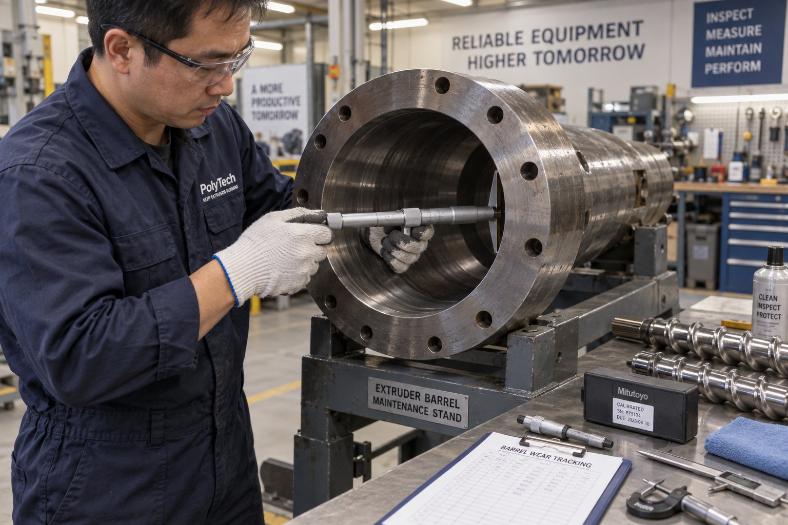
- Monthly or periodic overhauls: Measure screw flight diameter and barrel bore diameter at the feed, transition, and metering zones — track these readings over time to chart the direction of wear. Record gearbox oil temperature under stable load. Test motor insulation resistance to detect moisture ingress before a burn-out. Compare vacuum pump ultimate vacuum against its commissioning baseline. Measure cooling system delta-T and test water quality for fouling and hardness. Log cut-length variation across ten or more samples. Back up all PLC, HMI, and VFD parameters — a current backup prevents days of reprogramming after a controller replacement. Disassemble and polish the die flow channels to remove plate-out and carbonized buildup. Inspect all electrical grounding connections.
One reading tells you the current state. Repeated readings show the direction of wear. As production maintenance specialists emphasize, if melt pressure, gearbox temperature, cooling delta-T, or screw clearance moves in the wrong direction for two or three consecutive readings, schedule the repair before the line forces the schedule for you. That is the core principle: convert hidden drift into planned work, reducing the number of problems that ever reach the troubleshooting stage.
Do not overlook seasonal factors either. Hot weather reduces cooling tower efficiency and raises cabinet temperatures. High humidity creates condensation inside electrical enclosures and promotes rust on polished die surfaces. Dusty environments clog cabinet filters and contaminate bearing grease. Adjusting your maintenance rhythm to match environmental conditions prevents failures that standard checklists miss.
When and How to Replace Screws, Barrels, and Dies
Every component on the extrusion line has a wear lifecycle. Heater bands fail. Thermocouples drift. Vacuum pump vanes thin out. Haul-off belts lose grip. Cutter blades dull. These are routine consumables that any maintenance program accounts for.
The higher-stakes replacement decision involves the screw and barrel — the components that define your melt quality and, by extension, every measurable attribute of your finished profile. As discussed in the troubleshooting chapter, screw and barrel wear is not sudden. It is gradual, measurable, and predictable. The warning signs build over weeks and months:
- Output volume declining at constant screw speed, requiring RPM increases to hold throughput
- Motor current and specific energy consumption (Wh/kg) trending upward without a formulation change
- Melt temperature variation widening at the die head despite stable barrel setpoints
- Surface quality degrading incrementally — roughness, gloss loss, or die lines that process adjustments no longer resolve
- Visible scoring or hard-facing loss on screw flight tips when pulled for inspection
Running worn components past their functional limit does not save money. It costs money — in wasted energy, increased scrap, reduced throughput, and the risk of catastrophic failure that shuts the line down entirely. Industry analysis from Plastics Technology illustrates this clearly: a screw worn to 0.011 inches of clearance on a 100 mm extruder can force a 13% rate reduction to maintain acceptable discharge temperatures, directly cutting profitability and capacity. And a barrel with an iron-based bimetallic liner will typically outlast three screw service lives — but only if wear is tracked and the barrel is replaced before the liner is consumed.
The practical guidance is straightforward. Keep a spare screw in storage so swaps happen during planned downtime, not emergencies. Never refurbish a screw more than three times — each re-welding of hard-facing degrades the base metal and increases the risk of delamination. And when the barrel bore measurements confirm the liner has reached its wear limit, source a replacement built to the dimensional and metallurgical specifications your formulation demands.
For PVC profile, PVC pipe, foam board, and WPC extrusion manufacturers, NANHAIYA's custom and replacement conical twin screw barrels offer a practical path back to stable plasticizing performance. Purpose-engineered for the specific demands of rigid PVC processing — including bimetallic liner options for abrasive filler-loaded compounds and precision CNC machining for tight bore tolerances — these barrels are designed to restore your line's original output quality and energy efficiency without requiring a full extruder replacement. That distinction matters. Replacing the entire extruder when only the barrel has reached end-of-life is like buying a new car because the brake pads wore out. A precision-manufactured replacement barrel is an investment in continued production stability — one that pays for itself through recovered throughput, lower energy draw, and reduced scrap from the first shift it runs.
Dies, too, have a service life. Flow channel surfaces erode and roughen over thousands of production hours, especially when processing compounds with abrasive fillers. Regular polishing during monthly maintenance extends die life significantly, but eventually the flow geometry itself drifts too far from the original design to produce in-spec profiles. At that point, the die needs re-machining or replacement. Track your die's performance metrics — wall thickness consistency, surface quality, and pressure drop at constant throughput — the same way you track screw and barrel wear. Trend data tells you when replacement is approaching, giving you time to source the tooling before the line tells you it is too late.
This article set out to decode the entire journey of a PVC profile — from raw resin powder entering a high-speed mixer to a finished, dimensionally accurate product dropping onto a stacker. Along the way, you have seen how different profile types dictate different machine configurations, how the extrusion process transforms powder into product through eight interdependent stages, what each technical parameter on a spec sheet actually means for your production, and how die design, calibration, and the screw and barrel system work together to determine profile quality. You have also explored the total cost of ownership that extends far beyond the purchase price, the troubleshooting logic that separates quick fixes from component replacements, and the maintenance discipline that keeps plastic profile extruders running productively for years.
The value of this knowledge compounds with use. Every concept here — from compression ratios to vacuum calibration pressure to specific energy tracking — becomes a tool you carry into supplier meetings, production floor decisions, and capital planning conversations. Whether you are specifying your first pvc profile machine or optimizing a line that has been running for a decade, the fundamentals do not change. Understand your product requirements. Match them to the right equipment configuration. Monitor your process data. Maintain your wear components before they degrade your output. And when replacement is needed, source components engineered to restore — not compromise — your production standard.
Frequently Asked Questions About PVC Profile Making Machines
1. What components make up a complete PVC profile making machine?
A PVC profile making machine is not a single unit but an integrated extrusion line consisting of several synchronized components: a conical twin-screw extruder that melts and homogenizes the PVC compound, a precision die head that shapes the melt into the desired cross-section, a vacuum calibration table that locks in dimensions, a water-cooling tank, a haul-off unit that pulls the profile at a controlled speed, and an automatic cutter. Each component must operate in tight coordination — for example, haul-off speed must match extruder output precisely to avoid stretching or buckling the profile. Optional additions like co-extrusion units, lamination stations, or embossing rollers expand the range of profiles the line can produce.
2. How do I choose the right PVC profile extrusion machine for my product?
Start with your finished product, not the machine. Define the profile's cross-sectional complexity, wall thickness, chamber count, surface finish requirements, and target output rate in kg/h. Simple profiles like cable trunking can run on smaller conical twin-screw extruders such as the SJZ65/132 with basic dies, while multi-chamber window frames typically require larger models like the SJZ80/156 or SJZ92/188 with co-extrusion capability and multi-zone vacuum calibration. Always ask suppliers which specific profile geometry and PVC formulation their quoted output rate assumes, since actual throughput depends heavily on downstream cooling capacity and profile complexity.
3. What is the difference between vacuum calibration and spray calibration in PVC profile extrusion?
真空校准利用负压(通常为-0.02至-0.08 MPa)将仍处于柔软状态的挤出件拉向精密加工的不锈钢定径套筒,从而实现严格的尺寸精度和光滑亮泽的表面。它是窗框、门系统和线槽等复杂型材的首选方法。喷涂校准则利用水射流逐渐冷却型材,无需严格的定径约束,因此内部应力较低,但尺寸精度稍逊。喷涂系统适用于厚壁工业型材或应力降低比严格公差更为重要的应用。大多数硬质PVC型材生产线都采用真空校准作为主要方法。
4. PVC型材挤出机的螺杆和料筒应该多久更换一次?
由于磨损率取决于填料含量、生产时间和料筒材质,因此没有固定的更换周期。相反,应监测关键指标:螺杆转速恒定时产量下降、电机电流和单位能耗(Wh/kg)上升、模头熔体温度波动范围增大,以及检查时螺杆螺纹上出现可见的划痕。当工艺调整无法弥补磨损时,则需要更换料筒。双金属料筒的使用寿命通常比螺杆的使用寿命长得多。储备备用螺杆可以在计划停机期间进行计划性更换,而无需紧急停机。像南海亚这样的供应商提供定制和替换式锥形双螺杆料筒,旨在恢复原有的塑化性能,而无需更换整台挤出机。
5. 除了购置价格之外,PVC型材生产线最大的运营成本是什么?
原材料采购通常是最大的经常性成本,其次是能源消耗。在五到十年的时间跨度内,故障机电机、料筒保温、冷却泵和真空系统的总电力成本可能与设备最终价格相当甚至更高。其他主要成本类别包括人工、日常维护和备件(螺杆、料)降低运行成本的实用策略包括:在所有电机上安装变频驱动器;为料筒加装隔热套;保持螺杆和料筒的良好状态以防止能源浪费;以及每周跟踪单位湿度(Wh/kg)作为绩效指标。
Written by
Nanhaiya Technical Team
Zhoushan Nanhaiya Plastic Machinery Co., Ltd.
The Nanhaiya technical team supports screw and barrel manufacturing projects through application review, technical communication, custom manufacturing coordination, and production and quality control.
Discuss Your Application
Related Articles
More insights on screw barrel technology and plastics processing.

Extruder Machine Decoded: From Raw Pellet To Finished Product
Oct 6, 2026
Learn how an extruder machine works, compare single-screw vs. twin-screw types, and get expert guidance on specs, troubleshooting, and selection.
Read Article
PE Pipe Making Machine Decoded: From Raw Resin to Flawless Pipe
Oct 4, 2026
Learn how a PE pipe making machine works, from resin to finished pipe. Covers components, material grades, automation, troubleshooting, and buyer selection tips.
Read Article
Blown Film Extrusion Machine Decoded: From Resin to Finished Roll
Sep 28, 2026
Learn how a blown film extrusion machine works — components, process parameters, BUR calculations, multi-layer setups, resin compatibility, and maintenance tips.
Read ArticleLooking for something else?
Search by material, symptom or product and jump straight to the relevant page.
These are navigation suggestions based on keyword matching — not a quotation, not a delivery commitment, and not a substitute for engineering review. Final specification is confirmed by our engineers against your drawings and processed material.
Need help with screw barrel selection?
Share your machine model, processed material and application. Our team can help with pricing and technical support.