

What Is a Blown Film Extrusion Machine and Why It Matters
Imagine every grocery bag you carry, every roll of shrink wrap securing a pallet, and every barrier pouch keeping food fresh on a shelf. They all share a common origin: a blown film extrusion machine. This single category of equipment produces the vast majority of flexible plastic films used worldwide, yet the process behind it remains surprisingly misunderstood outside specialist circles.
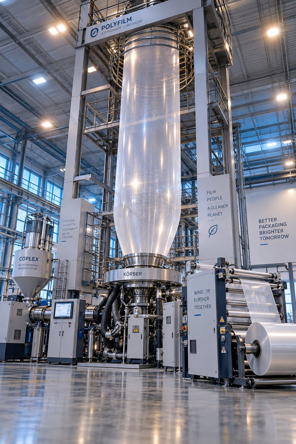
A blown film extrusion machine melts thermoplastic polymer pellets, forces the molten resin through an annular die, and inflates it with internal air pressure into a thin-walled tubular bubble. That bubble is air-cooled, collapsed into a flat layflat tube, and wound into finished rolls of film ready for conversion into bags, wraps, liners, and laminates.
Defining Blown Film Extrusion
At its core, blown film extrusion is a continuous thermomechanical process. Solid resin pellets enter a heated barrel where a rotating screw generates friction and applies external heat, transforming the polymer into a homogeneous melt. That melt is then pushed through a circular die opening, emerging as a molten tube. Compressed air injected through the center of the die inflates this tube into a bubble, stretching the material in two directions simultaneously — along the machine direction as haul-off rollers pull the film upward, and in the transverse direction as air pressure expands the bubble diameter. The result is a biaxially oriented film with mechanical properties distributed more evenly than most alternative processes can achieve.
Cooling occurs as ambient or forced air contacts the outer bubble surface, solidifying the polymer at a visible boundary called the frost line. Above this line, the film is solid enough to be guided through a collapsing frame, squeezed flat by nip rollers, and directed to a winder that produces the final roll.
Why Blown Film Extrusion Dominates Flexible Packaging
Several inherent advantages explain why blown film manufacturing accounts for such a large share of global flexible packaging output:
- Balanced MD/TD properties — simultaneous stretching in both the machine direction and transverse direction yields tougher, more tear-resistant film than processes that stretch in only one axis.
- Tubular or flat film from one line — the same equipment can produce seamless tubing for bags or slit-open sheeting for lamination, reducing the need for separate production lines.
- Low tooling costs — changing film width requires adjusting the blow-up ratio rather than purchasing a new die, unlike flat-die processes where die width dictates output width.
- Polymer versatility — LDPE, LLDPE, HDPE, nylon, EVOH, and metallocene blends can all be processed on properly configured blown film lines, making blown extrusion film adaptable across food packaging, agricultural mulch film, medical barrier films, and industrial stretch hoods.
Whether you are an operator looking to sharpen your process knowledge or a business buyer evaluating capital equipment, understanding each component and parameter of a blown film extrusion line is the foundation for better film quality, lower scrap rates, and smarter purchasing decisions. The architecture of that line — from hopper to winder — is exactly where the next section picks up.
Complete Anatomy of a Blown Film Extrusion Line
Picture a blown film line as a single, continuous pipeline — resin pellets enter one end, and finished rolls of film exit the other. Between those two points sit roughly a dozen interdependent components, each one shaping the melt, the bubble, or the final film in a measurable way. Knowing what every station does, and how it influences your end product, turns troubleshooting from guesswork into a systematic process.
The table below maps the full journey from raw-material intake to wound roll, listing every major component in the order the material encounters it. Use it as a quick-reference guide before diving into the detailed explanations that follow.
| Component | Primary Function | Influence on Final Film Quality |
|---|---|---|
| Hopper & Gravimetric Dosing Unit | Stores resin pellets and meters them into the extruder at a precise, consistent rate | Feed consistency directly controls gauge uniformity and layer-ratio accuracy in multi-layer structures |
| Extruder Barrel & Screw | Melts, homogenizes, and pressurizes the polymer through friction and external heat | Melt homogeneity determines optical clarity, gel count, and mechanical consistency |
| Screen Pack & Breaker Plate | Filters contaminants from the melt and eliminates the spiral flow pattern imparted by the screw | Reduces gels, fisheyes, and die-line defects; protects die channels from blockages |
| Die Head (Spiral or Stackable) | Distributes melt into a uniform annular flow to form the initial molten tube | Die design governs circumferential thickness uniformity and weld-line visibility |
| Air Ring (Single-Lip or Dual-Lip) | Delivers a controlled stream of cooling air onto the outer surface of the extruded bubble | Cooling rate and symmetry affect frost-line height, haze, gloss, and gauge variation |
| Internal Bubble Cooling (IBC) System | Circulates temperature-controlled air inside the bubble while regulating internal pressure | Enables higher output rates; improves bubble stability and thickness uniformity |
| Bubble Cage / Calibration Cage | Physically constrains the bubble diameter after the frost line to prevent sway and flutter | Stabilizes layflat width and reduces transverse-direction gauge variation |
| Collapsing Frame (A-Frame) | Gently flattens the round bubble into a folded layflat tube | Misalignment causes wrinkles, creases, and edge fold-overs that create waste |
| Nip Rollers | Seal the bubble by pressing the two film layers together and pull the film at a controlled speed | Nip pressure and alignment affect draw-down ratio, sealing of the bubble, and surface marks |
| Corona / Flame Treatment Station | Raises surface energy of the film to improve ink adhesion, lamination bonding, or printability | Undertreated film leads to poor print quality; overtreatment can degrade seal strength |
| Winder (Surface or Center Wind) | Winds the finished film onto cores to create uniform, shippable rolls | Tension control affects roll hardness, telescoping, and downstream convertibility |
Upstream Components — From Hopper to Die Head
Everything upstream of the die head serves a single purpose: deliver a perfectly homogeneous, contaminant-free melt at a stable pressure and temperature. The process starts at the hopper and gravimetric dosing unit, where resin pellets — and any additives or masterbatch — are weighed and blended before gravity-feeding into the extruder throat. Consistent dosing here prevents the composition drift that shows up later as color streaks or fluctuating film properties.
Inside the extruder barrel, the rotating screw does the heavy lifting. Think of the screw as three zones working in series. The feed section accepts solid pellets and conveys them forward. The compression zone reduces channel depth, compacting the pellets against the heated barrel wall so friction and conducted heat transform them into a viscous melt. Finally, the metering zone delivers that melt at a constant volumetric rate and pressure to the die. A well-matched screw geometry — proper L/D ratio, compression ratio, and channel depth — is what separates a blown film extruder machine that produces crystal-clear film from one that generates gels and gauge bands.
Before reaching the die, the melt passes through a screen pack supported by a breaker plate. The screens filter out degraded particles and foreign matter, while the breaker plate converts the helical flow created by the screw into straight-line flow. Without this step, spiral patterns can propagate all the way through the die and appear as visible defects on the finished film.
The die head itself — most commonly a spiral mandrel design — takes the linear melt stream and redistributes it into a uniform annular ring. Spiral dies use overlapping channels machined into the mandrel to gradually merge multiple flow streams, minimizing weld lines. Stackable dies are favored in multi-layer co-extrusion where each layer enters through its own distribution plate. In either case, the die's job is to ensure that every point around the annulus receives the same volume of melt at the same temperature. Any imbalance here translates directly into circumferential gauge variation in the finished film.
Downstream Components — From Air Ring to Winder
The moment molten polymer exits the die lip, it enters the cooling and forming section of the blown film line. The air ring — mounted directly above (or below, in downward extrusion configurations) the die — blows a precisely directed curtain of air onto the bubble's outer surface. Single-lip air rings deliver air from one slot, while dual-lip designs split the airflow into two independently adjustable streams for finer cooling control. Faster, more uniform cooling raises output rates and improves optical properties by reducing crystallite size in the solidified film.
Working in tandem with the air ring, the IBC system circulates conditioned air inside the bubble. It simultaneously cools the inner surface and regulates internal air volume, which controls bubble diameter. On any modern film extrusion machine, the IBC controller is the primary means of maintaining a stable layflat width minute after minute.
Above the frost line, the solidified bubble passes through a calibration cage — a ring of adjustable guide elements, rollers, or slats that prevent the bubble from swaying due to ambient air currents or vibration. The collapsing frame, often shaped like an inverted "A," then gently folds the round tube into a flat, two-ply layflat. Precise alignment of this frame is critical; even a few millimeters of offset introduce wrinkles that cannot be corrected downstream.
Nip rollers at the top of the tower press the two plies together, sealing the air inside the bubble and pulling the film upward at a controlled speed. From here, the film travels through an optional corona or flame treatment station — a surface-energy modification step essential for any film destined for printing or adhesive lamination. Finally, the winder rolls the treated film onto cardboard or plastic cores. Surface winders press a driven roller against the outside of the roll, while center winders drive the core shaft directly; each approach suits different film types and roll-size requirements.
How Each Component Affects Film Quality
You might notice a pattern in the table above: every single component maps to at least one measurable quality attribute. That is not a coincidence — it is the reason experienced operators diagnose problems by tracing them back to a specific station rather than adjusting random parameters.
- Gauge uniformity is shaped upstream by screw-and-barrel melt quality, at the die by flow distribution, and downstream by air-ring symmetry and IBC stability.
- Optical clarity hinges on melt homogeneity from the extruder, cooling rate from the air ring, and frost-line height — properties influenced by at least four components working together.
- Seal strength depends on proper resin selection and melt temperature (extruder), layer placement (die), and surface treatment level (corona station).
- Flatness and roll quality are governed by collapsing-frame alignment, nip-roller pressure balance, and winder tension control.
Understanding these cause-and-effect links across the full blown film extrusion line is what separates routine operation from true process mastery. Yet the components alone only tell half the story — the operating parameters you dial into each station determine whether the line produces premium film or generates scrap. Those parameters, and the step-by-step sequence that ties them together, are the focus of the next discussion.
Step-by-Step Blown Film Extrusion Process Explained
Knowing what each component does is one thing. Knowing exactly what happens to the polymer at every stage — and which parameters you can adjust to change the outcome — is where real process control begins. The blown film extrusion process unfolds in a precise sequence, and each step hands off to the next with very little room for error. Walk through it once with the operating variables in mind, and troubleshooting becomes far more intuitive.
The sequence starts well before resin ever touches the screw. Moisture-sensitive polymers like nylon or EVOH require pre-drying in desiccant hoppers, typically down to moisture levels below 0.02%. Even standard polyethylene grades benefit from consistent pellet temperature at the feed throat, because cold pellets change the friction dynamics inside the barrel. Once the gravimetric dosing system delivers a steady stream of dry pellets into the extruder, plasticization begins.
From Pellet to Melt — Plasticization and Die Flow
Inside the barrel, the rotating screw does three things simultaneously: it conveys the pellets forward, compresses them into a dense plug, and shears them against the heated barrel wall until they melt completely. Each polymer family demands a different melt temperature window. LDPE typically processes between 160 °C and 200 °C, LLDPE runs slightly hotter at 190 °C to 220 °C, and HDPE can require 200 °C to 240 °C depending on the grade's melt flow index.
Back pressure — the resistance the melt encounters downstream of the screw tip — plays a quieter but equally important role. Higher back pressure improves melt homogeneity by forcing the polymer through the screen pack more slowly, but excessive pressure raises melt temperature beyond the target window and can cause thermal degradation. Screw speed, meanwhile, directly controls output rate: increase RPM and more kilograms per hour flow through the die, but push too fast and the screw cannot fully plasticize every pellet, resulting in unmelts that show up as gels in the finished film.
The melt exits the die as a molten tube. A well-tuned die distributes polymer evenly around the full 360-degree annulus, so every point along the circumference carries the same wall thickness. Temperature uniformity at the die lips matters just as much — even a 2 °C to 3 °C variation across zones can create visible gauge bands.
Bubble Formation and the Frost Line
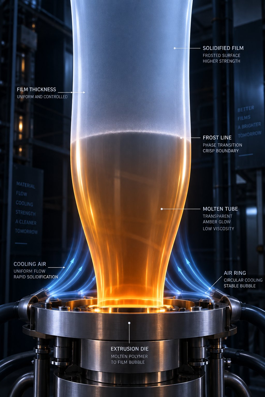
Here is where the blown film process becomes visually dramatic. Compressed air injected through the die center inflates the molten tube into a bubble, and the air ring simultaneously blasts cooling air onto its outer surface. The point where the bubble transitions from transparent melt to a slightly hazy solid is called the frost line — and its height above the die is one of the most powerful variables an operator controls.
Why does frost-line height matter so much? It determines how long the polymer stays in a semi-molten state, which directly governs crystallinity. A low frost line means rapid cooling, smaller crystallites, and better optical clarity — ideal for packaging films where transparency is a selling point. A higher frost line allows larger crystalline structures to form, boosting stiffness and barrier properties at the expense of some haze. In extrusion blown film operations, adjusting air-ring velocity raises or lowers the frost line within seconds. On lines equipped with IBC, operators fine-tune internal air pressure to further stabilize the bubble diameter while independently controlling the cooling profile.
Draw-Down Ratio, Die Gap, and Melt Temperature Interactions
Film thickness does not depend on any single setting — it emerges from the interaction of several dimensionless ratios. Draw-down ratio (DDR) quantifies how much the film is stretched in the machine direction. The formula for DDR is: die gap divided by the product of final film thickness and blow-up ratio (BUR). A higher DDR means the haul-off speed is pulling the film thinner relative to the die gap, orienting molecules in the machine direction and increasing MD tensile strength.
These parameters never act in isolation. Adjusting one shifts the balance of the others, so experienced operators think in terms of their interactions:
- Die gap — sets the initial wall thickness of the molten tube leaving the die.
- DDR — controls how much that wall is stretched in the machine direction, thinning the film and boosting MD orientation.
- BUR — determines transverse-direction stretch, thinning the film further while improving TD tear and tensile strength.
- Frost-line height — governs the cooling rate and therefore the crystallinity, haze, and stiffness of the solidified film.
Imagine you widen the die gap without changing anything else: the initial tube wall is thicker, so to hit your target film gauge you must either increase BUR, increase DDR (by raising haul-off speed), or both. Each choice steers the film's mechanical balance in a different direction. This is precisely why blow film extrusion is as much an art of parameter balancing as it is a manufacturing process — and why the blow-up ratio deserves a dedicated, deeper look.
Understanding Blow-Up Ratio and Its Impact on Film Properties
Of all the dimensionless numbers operators deal with daily, blow-up ratio stands out as the single most influential lever for controlling film behavior in the transverse direction. It appears in every process recipe, every troubleshooting guide, and every quality specification — yet its implications stretch far beyond a simple diameter measurement. Getting BUR right means engineering the mechanical balance your end-use application demands. Getting it wrong means fighting bubble instability, gauge bands, or film that tears too easily in one direction.
What Is Blow-Up Ratio and How to Calculate It
So, what is blow up ratio in practical terms? It is simply the ratio of the final inflated bubble diameter to the die diameter:
BUR = Final Bubble Diameter / Die Diameter
Because measuring bubble diameter directly on a running line is awkward, operators typically calculate it from the layflat width. Since a collapsed bubble forms a flat tube whose width equals half the circumference, the relationship becomes:
BUR = (2 × Layflat Width) / (π × Die Diameter)
Imagine you are running a die with a 125 mm diameter and your collapsed layflat measures 880 mm. Plugging those values in gives a BUR of roughly 4.5 — meaning the bubble inflated to about 4.5 times the die's diameter. An industrial-scale study on HDPE/LLDPE blend films used exactly that die size and recorded BUR values ranging from 2.2 to 5.0 across different product widths, demonstrating how widely a single machine can be tuned simply by adjusting internal air volume.
What does that stretch actually do to the film? Increasing BUR expands the bubble further in the transverse direction (TD), orienting polymer chains across the film's width. The result is higher TD tensile strength and improved TD tear resistance. At the same time, the material is being distributed over a larger circumference, which contributes to thinning the wall — a factor that must be balanced against machine-direction (MD) draw-down to hit the target gauge.
How BUR Affects Film Mechanical and Optical Properties
The trade-offs here are real and measurable. Research on blown HDPE/LLDPE blends has shown that BUR correlates strongly with both TD and MD elongation at break, with R-squared values between 0.91 and 0.94 in polynomial regression models. Increasing BUR from approximately 2.2 to 5.0 in those tests dramatically shifted the mechanical profile: TD elongation climbed above 1,000% at the lowest BUR values (thicker, narrower films) and settled into the 350–530% range at higher BUR values where films were thinner and wider. The relationship is not linear — it follows a second-degree polynomial curve, meaning there is a practical sweet spot for every resin blend.
General BUR ranges differ by polymer family. LDPE, with its long-chain branching and broad processing window, typically runs well between 2:1 and 4:1. LLDPE, though it demands more motor torque, operates across a similar range. HDPE — stiffer and more crystalline — can push to 4:1 through 5:1 or higher, partly because its high-stalk bubble configuration allows greater expansion before instability sets in.
Blow-up ratio is the primary tool operators use to engineer balanced MD/TD mechanical properties in blown film. Adjusting BUR shifts molecular orientation between the machine and transverse directions, directly controlling tensile strength, elongation, tear resistance, and impact performance.
Push BUR too high, however, and the bubble becomes unstable — oscillating, breathing, or even collapsing. Excessive transverse stretch can also thin the film beyond what the die gap and draw-down ratio can compensate for, creating gauge-control headaches. The key insight in blown film technology is that BUR is never set in isolation; it always works as part of a system.
BUR in Relation to DDR and Film Thickness
Final film gauge is the product of three interacting parameters, not one. Here is how they work together:
- Die gap sets the starting wall thickness of the molten tube — typically 0.8 mm to 2.0 mm depending on the die and the target film.
- BUR stretches that wall in the transverse direction, reducing thickness proportionally as diameter increases.
- DDR (draw-down ratio) stretches the wall in the machine direction as nip rollers pull the film faster than it exits the die, thinning it further.
The mathematical link is straightforward: final film thickness equals the die gap divided by the product of BUR and DDR. Double the blow up ratio while holding DDR constant, and you halve the film thickness — assuming the die gap stays the same. In practice, operators rarely change just one variable. Widening the layflat for a new product SKU means raising BUR, which thins the film, so the DDR may need to decrease (slower haul-off speed) to maintain the target gauge. Alternatively, a wider die gap can offset the extra thinning, though that shifts the melt's extensional strain history and may alter optical or mechanical properties.
This three-way interplay — die gap, BUR, and DDR — is why experienced operators describe film thickness control as a balancing act rather than a simple dial turn. It also explains why two films with identical thickness can perform very differently: a high-BUR, low-DDR film will have stronger TD properties and weaker MD properties compared to a low-BUR, high-DDR film of the same gauge. Choosing the right balance depends on the end-use demands, and that choice becomes even more nuanced when multiple polymer layers enter the picture.
Multi-Layer Blown Film Configurations from ABA to Eleven Layers
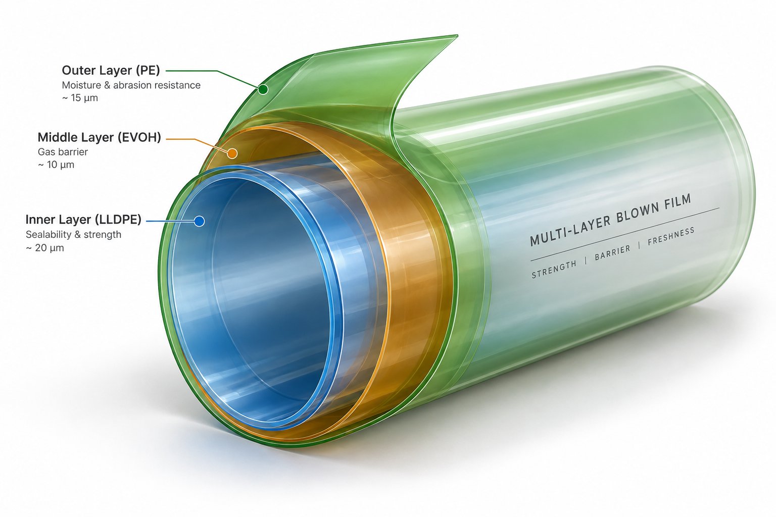
A single polymer layer can only do so much. When your packaging needs to block oxygen, resist punctures, seal reliably, and print beautifully — all at the same time — stacking multiple functional layers into one film structure is the answer. Multi-layer co-extrusion is the reason blown films have expanded from simple grocery bags into high-barrier medical pouches, modified-atmosphere food packaging, and heavy-duty industrial wraps. Each additional layer introduces a new material that targets a specific performance gap, and the configuration you choose shapes everything from capital cost to shelf-life extension.
Monolayer, ABA, and ABC Configurations
Monolayer blown films remain the simplest and most cost-effective option. A single extruder feeds one polymer — usually LDPE or LLDPE — through the die, producing films for commodity applications like bin liners, construction sheeting, and pallet stretch wrap. The advantages are obvious: lower equipment cost, simpler operation, and faster changeovers. The limitation is equally clear — you get the properties of one resin and nothing more.
Step up to a three-layer ABA structure and the picture changes. Two extruders feed the line: one supplies both outer skin layers (A), and the other delivers the core layer (B). Because the skins are identical, ABA films are inherently symmetrical, which makes them naturally resistant to curling — a practical benefit for automatic form-fill-seal machines. A common strategy is placing recycled resin or lower-cost filler in the core while keeping virgin material on the outside, cutting raw-material expenses without sacrificing surface quality.
An ABC configuration takes flexibility further. Three independent extruders allow each layer to use a different polymer, so you can optimize one surface for printability, the opposite surface for heat-seal performance, and the core for stiffness or cost reduction. ABC setups are the entry point for food and medical packaging films that need precise barrier control and enhanced toughness beyond what a symmetrical structure can deliver.
Five-Layer Through Eleven-Layer Co-Extrusion Systems
When barrier performance enters the conversation, three layers are no longer enough. True oxygen or moisture barriers require dedicated functional layers — typically EVOH or polyamide (PA) — that are chemically incompatible with the polyethylene skins surrounding them. That incompatibility demands adhesive "tie" layers on both sides of the barrier resin to prevent delamination. A 5 layer blown film line accommodates this perfectly with a structure like PE / Tie / EVOH / Tie / PE, making it the workhorse configuration for vacuum-sealed food packaging, MAP (modified atmosphere packaging), and medical-grade films.
Seven-layer blown film lines add further differentiation. The extra layers let engineers split functions even more precisely — for example, placing a stiff PA layer for puncture resistance alongside a separate EVOH layer for gas barrier, each bonded with its own optimized tie resin. The result is a film that approaches rigid-container performance while remaining fully flexible.
Nine- and eleven-layer systems push into territory that was once reserved for rigid packaging. With that many layers, producers can use thinner individual barrier layers (reducing expensive EVOH consumption), incorporate recycled content in non-critical layers, and fine-tune skin compositions independently for printing, sealing, or anti-fog performance. The multi layer blown films market has grown steadily around these advanced configurations because they deliver measurable cost savings per unit of barrier performance compared to fewer, thicker functional layers.
The table below summarizes every common configuration at a glance:
| Configuration | Typical Structure | Primary Applications | Barrier Capability | Relative Capital Cost | Typical End Markets |
|---|---|---|---|---|---|
| Monolayer | A | Bin liners, construction film, general-purpose bags | None (PE only) | Low | Commodity packaging, agriculture |
| 2-Layer (AB) | A / B | Lamination films, simple barrier wraps | Minimal | Low–Medium | Industrial wraps, lamination substrates |
| 3-Layer ABA | A / B / A | Recycled-core shopping bags, industrial films | Minimal | Medium | Retail bags, garbage bags, industrial packaging |
| 3-Layer ABC | A / B / C | Printable/sealable food packaging, medical films | Low–Moderate | Medium | Food packaging, medical pouches |
| 5-Layer | PE / Tie / EVOH / Tie / PE | Vacuum bags, MAP pouches, medical barrier films | High (oxygen barrier) | Medium–High | Fresh food, processed meat, pharmaceuticals |
| 7-Layer | PE / Tie / PA / EVOH / PA / Tie / PE | High-performance flexible pouches, cheese packaging | Very High | High | Dairy, ready meals, pet food |
| 9-Layer | Complex barrier + structural + sealant layers | Ultra-high-barrier laminates, pharmaceutical films | Exceptional | Very High | Pharmaceutical, specialty food, electronics |
| 11-Layer | Maximum functional differentiation per layer | Rigid-packaging replacement, advanced protective films | Exceptional | Highest | High-end food, pharma, military packaging |
Symmetrical vs Asymmetrical Layer Structures
Why do some blown films curl off the roll while others lie perfectly flat? The answer often comes down to structural symmetry. In a symmetrical structure — ABA, ABCBA, or any mirror-image arrangement — the stresses generated during cooling are balanced equally on both sides of the film. Neither surface contracts more than the other, so the film resists curling. This matters enormously for converters running high-speed packaging lines where a curled web causes jams, misregistration, and wasted material.
Asymmetrical structures, by contrast, deliberately sacrifice that balance to gain functional differentiation. Imagine a film designed for stand-up pouches: the outer surface needs high gloss and excellent ink adhesion for shelf appeal, while the inner surface requires a low-temperature sealant layer to form reliable pouch seams. These two requirements demand completely different polymers, making symmetry impossible — and unnecessary, because the converting process (lamination to a rigid substrate, for example) can counteract any curl tendency.
Choosing between symmetrical and asymmetrical designs is a downstream-driven decision. If the film will be used as a monoweb — unwound, printed, and formed into bags on the same line — symmetry prevents headaches. If it will be laminated to another substrate or if each surface serves a distinct purpose, asymmetry unlocks performance that balanced blown film lines simply cannot achieve with a mirror-image stack.
Layer configuration defines what a film can do. The resin loaded into each layer defines what it will do — and different polymers place very different demands on the extruder, screw, die, and cooling system that must process them. That material-to-machine relationship is where configuration choices become equipment-specification decisions.
Materials Compatibility and How Resins Shape Machine Design
Every blown film extrusion machine is built around assumptions about which polymer it will process. Change the resin family and those assumptions can collapse — melt temperatures shift, torque demands spike, screw geometry becomes inadequate, and the cooling strategy that worked perfectly yesterday produces unstable bubbles today. Understanding how different polymers interact with machine hardware is the bridge between choosing a layer structure on paper and actually producing quality film on the factory floor.
Polyethylene Variants — LDPE, LLDPE, HDPE, and Metallocene LLDPE
Polyethylene dominates polyethylene blown film extrusion, but treating all PE grades as interchangeable is one of the most common — and expensive — mistakes in the industry. Each variant has a distinct molecular architecture that dictates how it behaves inside the barrel, through the die, and as a cooling bubble.
LDPE is the most forgiving resin for blown film. Its highly branched molecular structure gives it a broad processing window, typically between 160 °C and 200 °C melt temperature. LDPE melts readily, generates relatively low torque on the screw, and produces stable bubbles across a wide range of operating conditions. A standard single-flighted screw can handle LDPE adequately, though a barrier screw with a mixing section still delivers better melt uniformity and fewer gels.
Switch to LLDPE and the difficulty escalates sharply. LLDPE's linear molecular chains create higher viscosity under processing conditions, which translates into significantly greater motor torque demand. An extruder running LDPE comfortably at 80 RPM can max out on torque at around 30 RPM when switched to LLDPE — a dramatic output reduction that catches many operators off guard. Processing temperatures typically run between 190 °C and 220 °C, and the narrower melt window demands a barrier screw design with strong mixing sections to prevent incomplete plasticization. Running LLDPE on a screw designed for LDPE is one of the most frequent sources of gels and fish-eyes in pe blown film extrusion.
HDPE introduces a different set of demands. Its high crystallinity and low melt elasticity mean that solids conveying becomes the bottleneck rather than melting. Grooved feed sections in the barrel throat are essential for consistent pellet intake, because smooth-bore designs cannot generate enough frictional grip on the stiff HDPE pellets to maintain stable output. Melt temperatures run hotter — typically 200 °C to 240 °C — and HDPE's high-stalk bubble formation enables BUR values of 4:1 to 5:1 or higher.
Metallocene LLDPE (mLLDPE) amplifies the challenges of standard LLDPE. Its narrow molecular weight distribution delivers superior seal strength and dart impact but pushes torque requirements even higher and tightens the processing window further. Screw designs for mLLDPE typically feature deeper channels and aggressive barrier-mixing sections to achieve complete homogenization without excessive shear heating.
Barrier and Specialty Resins — PA, EVOH, and Tie Layers
Multi-layer blown film lines rarely run polyethylene alone. Barrier packaging demands specialty polymers that bring their own processing complications — and each one requires a dedicated extruder configured for its unique behavior.
- Polyamide (PA / Nylon) — Melt temperature range: 230 °C to 270 °C. PA is highly hygroscopic, so it must be dried to below 0.02% moisture before processing; residual moisture causes hydrolytic degradation, visible as bubbles and streaks in the film. The screw geometry needs a gentle compression ratio to avoid overheating this thermally sensitive polymer, and extended L/D ratios (30:1 or above) ensure complete plasticization. Cooling must be moderate to allow the PA layer to crystallize properly and deliver its puncture-resistance benefits.
- EVOH (Ethylene-Vinyl Alcohol Copolymer) — Melt temperature range: 190 °C to 230 °C. EVOH is extremely moisture-sensitive; exposure to humidity degrades its oxygen-barrier properties and can cause processing instability. It must always be encapsulated between tie layers in the die, never exposed as a skin. Screw design should minimize residence time to prevent thermal degradation, and dedicated small-diameter extruders are preferred because the EVOH layer often represents only 5% to 10% of total film thickness.
- Tie-layer adhesive resins — Melt temperature range: 190 °C to 220 °C. These modified polyolefins bridge chemically incompatible layers — bonding PE to PA, or PE to EVOH — by providing reactive functional groups at each interface. Tie resins are relatively easy to process but demand precise temperature matching with adjacent layers; if the tie melt is too cool relative to the barrier resin, interfacial adhesion suffers and the finished film delaminates under stress.
How Resin Choice Drives Machine Specification
This is where polymer film extrusion theory meets equipment purchasing reality. A plant running primarily HDPE needs grooved-feed extruders with high-torque drives, barrier screws optimized for stiff crystalline polymers, and air rings capable of supporting tall stalk bubbles. A facility focused on LDPE/LLDPE blends requires barrier-mixing screws designed around the LLDPE fraction's torque profile, standard smooth-bore feed sections, and dual-lip air rings tuned for lower frost-line heights. A co-extrusion line producing blown polyethylene film with PA or EVOH barrier layers must add small, dedicated extruders with drying systems, separate temperature-control zones, and die configurations that protect moisture-sensitive barrier resins from humidity exposure.
The lesson is straightforward: specifying a blown film extrusion machine based solely on output rate or die width, without matching screw design, barrel configuration, and cooling strategy to the primary resin family, is a recipe for underperformance. Two lines with identical nameplate specifications can produce dramatically different results if one is optimized for polyethylene film extrusion and the other is set up for barrier co-extrusion. The resin defines the machine — not the other way around.
Material compatibility shapes the hardware. Yet even a perfectly matched machine-and-resin combination faces a fundamental question: should the film be made with a blown process or a cast process? Each technology handles the same polymers differently, and the trade-offs between them determine which products belong on which line.
Blown Film vs Cast Film Extrusion — A Structured Comparison
Both blown and cast film extrusion start with the same raw materials — thermoplastic pellets melted into a viscous fluid and shaped into thin, continuous film. Yet the moment that melt leaves the die, the two processes diverge dramatically. The shape of the die, the method of cooling, and the direction of stretch all differ, producing extruded films with fundamentally different performance profiles. Choosing the right process is not about which one is "better" — it is about which one aligns with the mechanical, optical, and economic demands of your specific application.
Process Differences Between Blown and Cast Film Extrusion
In plastic film extrusion, the die geometry sets the stage for everything downstream. A blown film line pushes melt through an annular (ring-shaped) die, inflates it with air into a tubular bubble, and cools it relatively slowly using ambient or forced air. A cast film extrusion line, by contrast, forces melt through a flat slot die onto a highly polished, internally cooled chill roll that quenches the film almost instantly on contact.
That cooling-rate difference is the single most important variable separating the two families of film. Rapid chill-roll quenching freezes the polymer chains before large crystalline structures can form. The result is a film with exceptional optical clarity and gloss — you can practically see through it like glass. Slow air cooling on a blown film line gives polymer chains more time to organize into crystallites, producing a tougher, slightly hazier film with a tighter molecular structure that improves barrier performance against moisture and gases.
Orientation tells the rest of the story. Blown film stretches biaxially — simultaneously in the machine direction (MD) through haul-off tension and in the transverse direction (TD) through bubble inflation. Cast film stretches primarily in the machine direction as the chill roll draws the melt away from the die at high speed, leaving TD orientation comparatively low. This imbalance means cast film is inherently stronger in one direction, while blown film distributes its strength more evenly across both axes.
Mechanical, Optical, and Performance Trade-Offs
When evaluating blown and cast film products side by side, the trade-offs become clearest in a structured comparison. The table below maps every key performance attribute across both processes so buyers and engineers can weigh the differences that matter most for their target application.
| Performance Attribute | Blown Film | Cast Film |
|---|---|---|
| MD/TD Strength Balance | Well-balanced due to biaxial orientation | MD-dominant; weaker in TD |
| Puncture Resistance | High — biaxial stretch creates tough, resilient film | Moderate — unidirectional orientation reduces cross-direction toughness |
| Optical Clarity | Moderate — slower cooling produces more haze | Excellent — rapid quenching minimizes crystallinity and maximizes transparency |
| Thickness Uniformity | Good with modern air rings and IBC; inherently more variable than cast | Very tight — flat die and chill-roll contact provide precise gauge control |
| Production Speed | Moderate — cooling rate limits line speed | High — fast chill-roll quenching enables greater throughput |
| Capital Cost | Moderate — simpler tooling, width changes via BUR adjustment | Higher — wide chill rolls and flat dies are expensive; width changes require new dies |
| Gauge Range | Broad — from thin bags to heavy-duty sacks | Typically thin to medium gauge; heavy-gauge film is less practical |
| Barrier Structure Suitability | Excellent — co-extrusion up to 11 layers is well-established | Good for barrier layers, though multi-layer cast configurations are less common at high layer counts |
In short, blown film wins on toughness, balanced properties, and barrier versatility. Cast film wins on clarity, gauge precision, and raw production speed. Neither process is universally superior — each dominates a different segment of the plastic film extrusion landscape.
When to Choose Each Process
Practical decision-making comes down to matching process strengths to end-use requirements. Blown film is the preferred technology for heavy-duty sacks, agricultural mulch and greenhouse covers, stretch hood film, industrial liners, and multi-layer barrier packaging where puncture resistance and balanced MD/TD toughness are non-negotiable. These applications subject the film to rough handling, sharp contents, or prolonged outdoor exposure — conditions where biaxial orientation and a tighter crystalline structure provide a measurable performance edge.
Cast film extrusion earns its place in applications where visual appearance and line speed take priority. Food wrap requiring retail-shelf transparency, thin-gauge pallet stretch film produced at maximum throughput, and high-clarity lamination webs all benefit from the rapid quenching and smooth surface finish that chill-roll cooling delivers. If your product needs to look pristine on a supermarket shelf or if you are chasing maximum kilograms-per-hour on commodity film, cast is the more efficient path.
Choose blown film when toughness and balanced strength drive the specification; choose cast film when optical clarity and production speed define success.
Of course, selecting the right process is only the first equipment decision. Within a blown film line, the extruder screw and barrel are the components most directly responsible for converting raw resin into a consistent, defect-free melt — and their condition determines whether the line delivers premium film or generates costly scrap.
The Screw and Barrel as the Heart of Blown Film Performance
Every quality attribute discussed so far — gauge uniformity, optical clarity, mechanical balance, barrier integrity — depends on one precondition: a perfectly homogeneous melt arriving at the die at a stable temperature and pressure. The screw and barrel are the components that either deliver that melt or sabotage it. Think of them as the cardiovascular system of a blown film extruder — when they function well, every downstream station performs at its best. When they degrade, problems cascade through the entire line in ways that mimic a dozen other root causes, making diagnosis frustrating and costly.
Why Screw and Barrel Engineering Determines Film Quality
Screw geometry is not a one-size-fits-all proposition. Four design parameters — L/D ratio, compression ratio, channel depth, and barrier flight configuration — collectively govern how efficiently the polymer melts, how uniformly heat distributes through the melt, and how many kilograms per hour the extruder can push through the die.
The L/D ratio (screw length divided by its diameter) determines residence time. Longer screws — 30:1 or higher — give the resin more time in contact with the heated barrel, improving melt homogeneity for thermally sensitive polymers like nylon or EVOH. Shorter screws process faster but risk delivering partially unmelted pellets to the die, which appear as gels in the finished film.
The compression ratio — the depth of the feed channel divided by the depth of the metering channel — controls how aggressively the screw compacts and shears the resin. A ratio that is too low leaves unmixed regions; too high generates excessive shear heat, pushing melt temperature beyond the target window and degrading optical properties. For a film blowing extruder machine processing LLDPE blends, compression ratios typically range from 2.5:1 to 3.5:1, while HDPE applications often require lower ratios paired with grooved feed zones to manage the stiffer pellets.
Barrier flight designs add a secondary flight that separates the solid bed from the melt pool inside the screw channel. This prevents solid fragments from bypassing the melting zone — a common cause of fisheyes on finished film. Combined with dispersive or distributive mixing elements near the screw tip, barrier screws produce the thermal uniformity that blown film machinery demands for tight gauge tolerances.
A poorly designed or worn screw introduces melt-temperature variation across the annular die, and even a 2 °C to 3 °C spread translates into visible gauge bands on the roll. The film extruder that produced flawless product last year can begin generating rejects this year if screw wear goes undetected — which raises a critical question: how do you recognize wear before it wrecks your output?
Signs of Screw and Barrel Wear and When to Replace
Wear is inevitable. Every rotation of the screw pushes polymer melt over the flight tips, and over thousands of operating hours, the clearance between flight and barrel wall gradually widens. As Plastics Technology notes, this widening flight clearance forces operators to increase screw speed to maintain the same output rate — which in turn raises discharge temperature and energy consumption. For a blown film application, a screw with roughly 0.011 inches of wear can push discharge temperatures high enough that the rate must be cut by as much as 13%, directly reducing line profitability.
Two primary wear mechanisms drive the deterioration:
- Abrasive wear — caused by mineral fillers (calcium carbonate, silica, glass fiber) or by solid pellets wedging against barrel walls in the compression zone. This type grinds away flight hard-facing and scores the barrel liner.
- Corrosive wear — triggered by acidic byproducts from thermally degraded resin, especially PVC, fluoropolymers, or flame-retardant compounds. Corrosion pits the barrel surface and undermines the bimetallic liner over time.
Recognizing wear early prevents a slow bleed of quality and profit. Watch for these indicators:
- Rising melt temperature at constant RPM — wider flight clearance reduces pumping efficiency and increases shear heating as melt leaks back over the flights.
- Increasing specific energy consumption — the motor works harder to deliver the same throughput because more material recirculates instead of moving forward.
- Falling output rate at maximum RPM — the screw can no longer build enough pressure to maintain the target extrusion rate.
- Deteriorating film quality — gauge bands, increased gel counts, and haze shifts that cannot be corrected with die or air-ring adjustments often trace back to inconsistent melt delivery from a worn screw.
Industry guidelines suggest replacing or refurbishing a screw when flight clearance reaches roughly four times its original value — but for critical applications like medical or food-contact blown film, replacement at two times the original clearance is a safer threshold. A worn screw should never be refurbished more than three times, because repeated hard-facing welds degrade the base metal and increase the risk of delamination. Keeping a spare screw on hand eliminates extended downtime during change-outs, and any time the screw is pulled, the barrel bore should be measured — an iron-based bimetallic liner typically lasts about three times the service life of a screw.
Choosing the Right Replacement Screw and Barrel
Replacing a worn screw is not simply ordering the same part number again. The replacement decision is an opportunity to match screw design to your current — not original — resin portfolio. Three selection criteria matter most:
1. Match screw geometry to the primary resin family. If your product mix has shifted toward LLDPE or metallocene grades since the original screw was specified, the replacement should incorporate a barrier flight design with stronger mixing sections and deeper feed channels to handle the higher torque demand. A screw designed around LDPE will underperform on LLDPE and overheat mLLDPE — costing you output and quality every hour it runs.
2. Choose metallurgy for your specific wear environment. Abrasive compounds call for tool-steel flights with tungsten-carbide hard-facing or bimetallic barrel liners rated for high-filler loads. Corrosive resins demand nickel-alloy barrel liners and corrosion-resistant screw coatings. Spending slightly more on the right metallurgy can extend service life by 25% or more, cutting long-term replacement costs significantly.
3. Ensure dimensional compatibility with the existing drive. The replacement screw must match the extruder's shank diameter, spline configuration, and thrust-bearing capacity. Mismatches cause premature bearing failure and dangerous mechanical overloads.
When evaluating film extruder suppliers for replacement components, look for manufacturers that specialize in film-specific screw and barrel designs rather than generic all-purpose screws. Film extrusion demands tighter thermal control and narrower processing windows than pipe or profile extrusion, and a supplier that understands those differences will deliver better-matched components. NANHAIYA, for example, engineers custom and replacement single screw barrels across pipe, film, sheet, pelletizing, and recycling extrusion lines — with film-specific designs that account for the thermal sensitivity and precise melt-quality requirements of blown film production. Sourcing from a specialist with that range of application knowledge helps ensure the replacement barrel and screw are optimized for your exact resin and process conditions rather than adapted from an unrelated extrusion discipline.
Screw and barrel health is the foundation of consistent melt quality — but it is only one piece of a broader maintenance and machine-selection puzzle. The same principles that guide replacement-component decisions also inform how you diagnose everyday film defects and how you evaluate a new line purchase from the ground up.
Troubleshooting Defects, Maintenance, and Machine Selection
A perfectly engineered screw and barrel can still produce defective film if the rest of the line is neglected — and a flawlessly maintained line can still disappoint if it was the wrong machine for the job in the first place. This final section ties every preceding discussion together by addressing the three questions operators and buyers ask most often: why is my film failing, how do I prevent failures before they start, and how do I choose the right blown film machines for my operation?
Troubleshooting Common Blown Film Defects
When film quality drops, the instinct is to start adjusting whatever is closest — die-lip bolts, air-ring fans, haul-off speed. Resist that instinct. Effective troubleshooting means identifying the defect first, then tracing it back to a root cause before touching a single parameter. The table below maps the five most frequent quality problems to their likely origins and the corrective actions that resolve them.
| Defect Type | Common Root Causes | Corrective Actions |
|---|---|---|
| Gauge Variation (thickness bands or uneven caliper across the web) | Die-lip contamination or buildup; uneven air-ring flow distribution; worn screw or barrel allowing inconsistent melt delivery; temperature variation across die zones | Clean die lips and inspect for damage; recalibrate air-ring gap uniformity; measure screw flight clearance and replace if worn beyond tolerance; verify die-zone heater function and thermocouple accuracy |
| Bubble Instability (oscillation, breathing, or helical movement) | Incorrect BUR for the resin and die combination; melt-temperature fluctuation from degraded screw performance; ambient drafts or poor tower enclosure; IBC pressure imbalance | Reduce BUR incrementally until the bubble stabilizes; check barrel-zone temperatures for deviation; shield the bubble path from plant airflow; recalibrate IBC sensors and valves |
| Gels and Fisheyes (small hard spots or unmelted particles embedded in the film) | Thermally degraded resin from excessive residence time; inadequate melt mixing due to worn or improperly designed screw; cross-contamination from previous resin run; dirty screen pack | Purge the extruder thoroughly between material changes; upgrade to a barrier screw with dispersive mixing elements; replace screen packs on a scheduled basis; reduce melt temperature if degradation is thermal |
| Wrinkles (creases, fold-overs, or uneven layflat) | Misaligned collapsing frame relative to the bubble center; uneven nip-roller pressure across the web width; inconsistent bubble diameter causing variable layflat width | Realign the collapsing frame using a laser guide or plumb reference; adjust nip-roller pressure evenly and check roller surface for damage; stabilize bubble diameter via IBC tuning |
| Haze (reduced transparency or milky appearance) | Frost-line height too high, allowing excessive crystallite growth; die-lip imperfections creating surface roughness on the melt; melt temperature too low for the resin grade | Increase air-ring velocity to lower the frost line and accelerate cooling; polish or replace damaged die lips; raise melt temperature within the resin manufacturer's recommended window |
You will notice a pattern: screw and barrel condition appears in multiple rows. Swallow Machinery's troubleshooting guidance reinforces this point — many blown film defects that appear to originate at the die or air ring actually trace back to inconsistent melt quality upstream. Fixing the symptom at the die while ignoring a worn screw only guarantees the problem returns.
Preventive Maintenance Best Practices
Reactive maintenance — waiting for something to break — is the most expensive maintenance strategy in blown film production. A single unplanned stoppage on a high-performance extrusion machine running 24/7 can waste hours of production time and hundreds of kilograms of off-spec film. Proactive, scheduled maintenance eliminates the majority of those surprises.
Structure your maintenance program around these intervals:
- Daily — Inspect die lips for resin buildup and wipe clean. Verify air-ring gap uniformity visually. Check hopper levels and dosing-system calibration. Log melt temperature, pressure, and motor load readings to establish a baseline for trend monitoring.
- Weekly — Inspect nip-roller surfaces for scoring or uneven wear. Check collapsing-frame alignment against the bubble centerline. Verify winder tension settings and examine roll quality for signs of telescoping or soft edges. Confirm that web-guiding systems are tracking correctly without drift.
- Monthly — Measure screw and barrel temperatures at each zone against setpoints to catch failing heaters or thermocouples early. Inspect screen packs and breaker plates for wear or partial blockage. Lubricate gearbox per the manufacturer's schedule and check oil quality.
- Quarterly to Annually — Pull the screw for visual and dimensional inspection. Measure barrel bore diameter at multiple points to detect wear. Perform a full die disassembly, cleaning, and polishing. Calibrate IBC sensors and air-ring blower balance. Inspect electrical connections, motor insulation, and drive-system components.
Screw and barrel inspection deserves special emphasis because wear in these components degrades output gradually — often too slowly for operators to notice shift by shift, yet fast enough to cost thousands in scrap over a quarter. When replacement is needed, sourcing precision-matched components is a critical part of any lifecycle maintenance strategy. Suppliers like NANHAIYA, which engineers replacement single screw barrels specifically for film extrusion applications, can match metallurgy and geometry to your exact resin and process conditions — ensuring the new components restore original performance rather than introducing a new set of compatibility issues.
Beyond individual components, blown film machine automation plays an increasingly important role in preventive maintenance. Modern PLCs log process variables continuously, and trend analysis of melt pressure, motor current, and discharge temperature can flag developing wear weeks before it produces a visible film defect. Investing in data-logging capability — even on older film blowing machine platforms — turns maintenance from a calendar-based chore into a condition-based strategy that targets interventions exactly when they are needed.
Key Criteria for Selecting a Blown Film Machine
Whether you are a first-time buyer or expanding an existing operation, machine selection follows a logical sequence. Industry experience from blown film extruder manufacturers consistently shows that the most expensive mistake is starting with a budget and working backward rather than starting with the product and working forward. Define these parameters in order:
- Primary resin types and blends — This determines screw design, barrel configuration, feed-section type, and motor torque requirements. A plant running HDPE needs fundamentally different hardware than one focused on LLDPE/LDPE blends.
- Film structure — Monolayer, ABA, ABC, or 5+ layer co-extrusion? Layer configuration is the hardest decision to reverse later. Upgrading a monolayer line to multi-layer essentially means buying a new machine.
- Output rate targets — Size the extruder for sustained throughput at roughly 80–90% of maximum screw speed, not peak capacity. A machine running constantly at its ceiling produces more scrap and wears faster than one operating with headroom.
- Finished-film width and gauge range — Die diameter multiplied by BUR and a factor of approximately 1.57 determines maximum layflat width. Size the die for your widest regular order, and confirm the cooling system can handle your thinnest gauge target without bubble instability.
- Downstream requirements — Will the film be printed, laminated, or converted inline? Corona treatment, oscillating haul-off, and winder type all depend on what happens after the roll leaves your floor.
When evaluating blown film extrusion machine manufacturers, look beyond the purchase price. As the total-cost-of-ownership data from experienced converters reveals, the machine price typically represents only 3–4% of an 8-year operating cost — while scrap rate differences between a well-configured line and a poorly matched one can dwarf that purchase premium within 18 months. Ask any prospective blown film machine supplier for thickness-variation guarantees at your specific film width and material, request factory-acceptance-test data with your resin, and contact reference customers who have run a similar configuration for at least a year.
The right blown film machine manufacturer does not just sell you hardware — they match die geometry, screw design, cooling configuration, and control architecture to the exact film product you need to produce profitably. Every section of this article — from BUR calculations and resin compatibility to screw metallurgy and defect diagnosis — feeds into that single decision. Master the fundamentals, and the machine specification writes itself.
Blown Film Extrusion Machine FAQs
1. What is the main difference between blown film and cast film extrusion?
The core difference lies in die geometry and cooling method. Blown film uses an annular die with air-based cooling, producing a biaxially oriented film with balanced MD/TD strength and superior toughness. Cast film uses a flat slot die with rapid chill-roll quenching, yielding film with exceptional optical clarity and tighter gauge control but weaker transverse-direction properties. Blown film is preferred for heavy-duty sacks, barrier packaging, and agricultural film, while cast film suits high-clarity food wraps and high-speed commodity applications.
2. How does blow-up ratio (BUR) affect blown film quality?
BUR — calculated as the final bubble diameter divided by the die diameter — controls how much the film stretches in the transverse direction. Increasing BUR improves TD tensile strength, tear resistance, and can enhance gauge uniformity by distributing material more evenly around the bubble circumference. However, pushing BUR too high causes bubble instability and thinning that may exceed what the die gap and draw-down ratio can compensate for. Typical BUR ranges are 2:1 to 4:1 for LDPE, and 4:1 to 5:1 or higher for HDPE. BUR always works alongside DDR and die gap to determine final film thickness.
3. How do you know when to replace a blown film extruder screw and barrel?
Key warning signs include rising melt temperature at constant screw RPM, increasing specific energy consumption, falling output at maximum speed, and deteriorating film quality such as gauge bands or higher gel counts. These symptoms result from widening flight clearance caused by abrasive or corrosive wear. Industry practice recommends replacement when flight clearance reaches roughly four times its original value, or at two times for critical food-contact or medical film applications. Suppliers like NANHAIYA (nhyscrews.com) offer custom replacement single screw barrels engineered specifically for film extrusion, ensuring precise metallurgical and geometric matching to restore original performance.
4. Why does resin type matter when specifying a blown film extrusion machine?
Different polymer families impose fundamentally different demands on the extruder. LDPE processes easily on standard screws, while LLDPE requires barrier screw designs with strong mixing sections and significantly higher motor torque. HDPE needs grooved-feed barrel sections for consistent solids conveying plus higher processing temperatures. Barrier resins like PA and EVOH require dedicated small-diameter extruders, pre-drying systems, and precise temperature control. Specifying a machine based on output rate alone — without matching screw geometry, barrel configuration, and cooling strategy to the primary resin — leads to underperformance, excessive scrap, and premature component wear.
5. What are the advantages of multi-layer blown film over monolayer film?
Multi-layer co-extrusion allows each layer to serve a distinct function — such as oxygen barrier, moisture resistance, puncture toughness, printability, or heat sealability — that no single polymer can deliver alone. A 5-layer structure like PE/Tie/EVOH/Tie/PE enables high oxygen barrier packaging for fresh food and medical products. Seven- to eleven-layer configurations further optimize barrier performance while reducing expensive barrier-resin consumption through thinner individual layers and incorporating recycled content in non-critical layers. While capital costs increase with layer count, the per-unit barrier performance improves, making multi-layer lines more cost-effective for demanding packaging applications.
Written by
Nanhaiya Technical Team
Zhoushan Nanhaiya Plastic Machinery Co., Ltd.
The Nanhaiya technical team supports screw and barrel manufacturing projects through application review, technical communication, custom manufacturing coordination, and production and quality control.
Discuss Your Application
Related Articles
More insights on screw barrel technology and plastics processing.

Extruder Machine Decoded: From Raw Pellet To Finished Product
Oct 6, 2026
Learn how an extruder machine works, compare single-screw vs. twin-screw types, and get expert guidance on specs, troubleshooting, and selection.
Read Article
PE Pipe Making Machine Decoded: From Raw Resin to Flawless Pipe
Oct 4, 2026
Learn how a PE pipe making machine works, from resin to finished pipe. Covers components, material grades, automation, troubleshooting, and buyer selection tips.
Read Article
PVC Profile Making Machine Decoded: From Raw Resin To Profit
Oct 3, 2026
Learn how a PVC profile making machine works — extrusion process steps, key technical parameters, die design, calibration methods, maintenance, and total cost of ownership.
Read ArticleLooking for something else?
Search by material, symptom or product and jump straight to the relevant page.
These are navigation suggestions based on keyword matching — not a quotation, not a delivery commitment, and not a substitute for engineering review. Final specification is confirmed by our engineers against your drawings and processed material.
Need help with screw barrel selection?
Share your machine model, processed material and application. Our team can help with pricing and technical support.