

What Twin Extruder Screw Design Really Means and Why It Matters
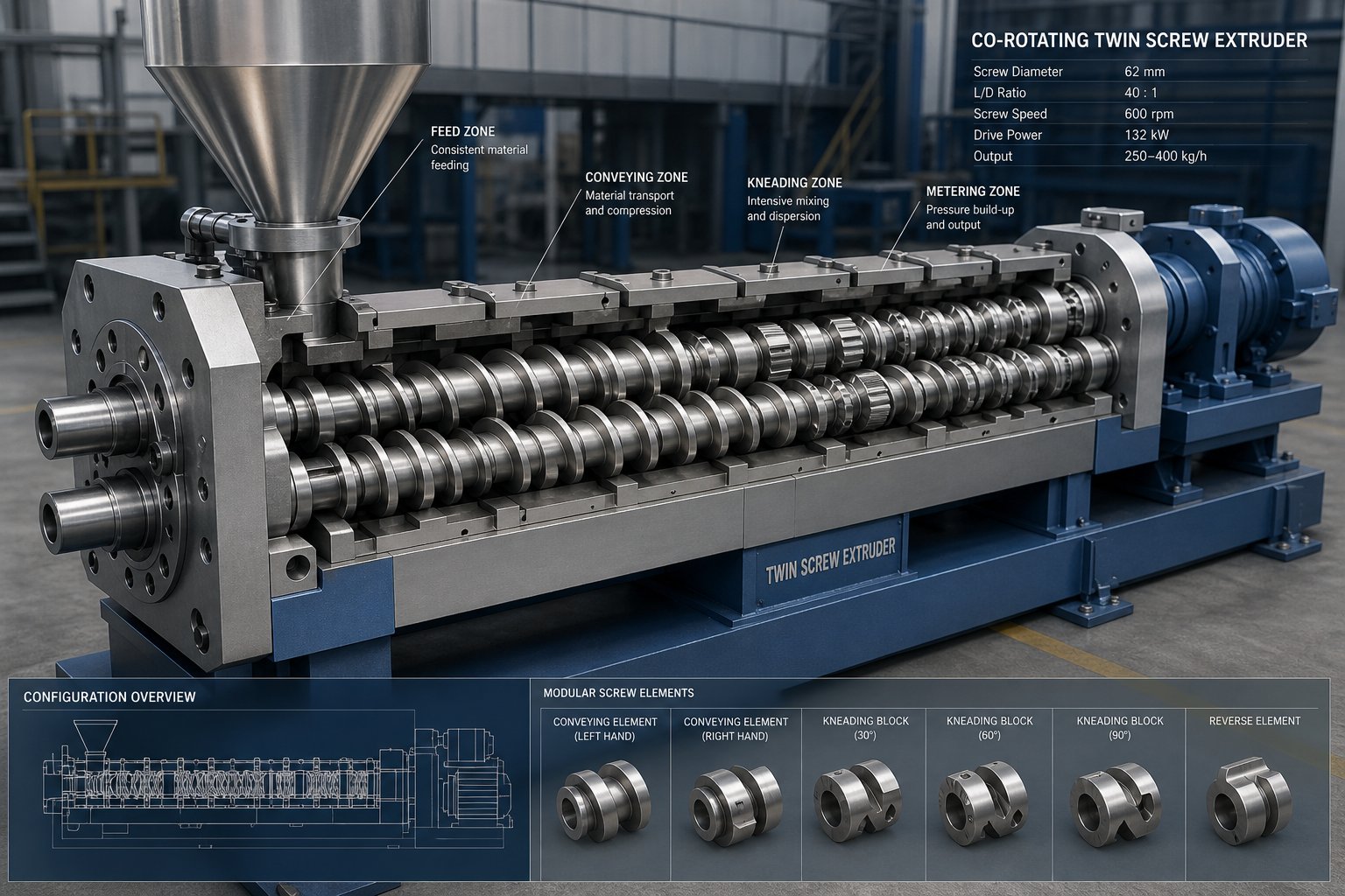
Imagine two rotating screws, each assembled from dozens of individual segments, locked together on a shaft inside a heated barrel. Every segment you choose, and every position you place it in, reshapes how your polymer melts, mixes, vents, and exits the die. That decision-making process is the essence of twin extruder screw design, and it separates a mediocre extrusion line from a finely tuned one.
Defining Twin Extruder Screw Design in Modern Processing
Twin extruder screw design is the engineering discipline of selecting, sequencing, and configuring modular screw elements along a barrel to achieve targeted processing outcomes, including precise control of mixing quality, melt temperature, residence time, and throughput for a given material system.
Unlike single-screw extruders that rely on a one-piece screw geometry fixed at manufacture, twin screw extruders use a segmented, modular architecture where individual elements are assembled on a screw shaft. This modular screw element configuration means you can rearrange conveying elements, kneading blocks, and specialized mixing segments in virtually limitless combinations. The result is an iterative, application-specific design process: no single "gold standard" profile exists because every polymer system exhibits unique flow behavior influenced by temperature, shear rate, and extruder geometry.
Three basic element categories, flighted (conveying) elements, mixing (kneading) elements, and zoning elements, form the building blocks of every profile. Some elements are multifunctional, but the core principle remains the same: each segment serves a deliberate purpose at a deliberate location along the barrel length.
Why Screw Profile Is the Most Critical Process Variable
You'll often hear that barrel temperature and feed rate drive extrusion outcomes. They matter, of course, but screw geometry governs the fundamental physics of the process. The profile dictates where and how material melts through viscous dissipation, how intensely components are mixed, how long they reside in each functional zone, and how much pressure builds at the die. Adjust barrel temperature and you nudge the system; reconfigure the screw profile and you redefine it.
Consider the five distinct shear regions present in any twin screw cross-section: the screw channel, the overflight gap, the lobal pool, the apex zones, and the intermesh region. As research on continuous mixing has shown, four of these five regions operate independently of screw fill level, meaning their mixing intensity is hardwired into the element geometry itself. Screw speed and feed rate modulate exposure time, but the element design sets the ceiling on what is physically possible.
This article is built for process engineers who already understand the basics and need optimization-level guidance. The sections ahead break down element types, stagger angles, mixing modes, metallurgy, simulation tools, and scale-up strategy, each one a lever that experienced practitioners pull when a profile needs to perform better. The first lever worth examining? The extruder classification itself, because the type of twin screw machine you are working with fundamentally constrains every element choice that follows.
Twin Screw Extruder Classifications That Shape Every Design Decision
Every screw element you select, every kneading block angle you specify, and every sequencing choice you make is bounded by one upstream decision: the type of twin screw extruder on your production floor. The machine architecture does not merely influence your profile options; it defines the geometry of what is physically possible. Understanding these classification categories at an engineering level is the prerequisite for meaningful profile optimization.
Co-Rotating vs Counter-Rotating Intermeshing Designs
The most consequential distinction in twin screw extrusion is the direction the screws turn. In a co-rotating configuration, both screws spin the same way, and a fully intermeshing geometry is almost always adopted. This creates an open screw channel structure where material flows in a characteristic figure-eight ("∞") pattern, continuously transferring between screws at the intermesh region. The result is a self-wiping geometry that minimizes dead zones, keeps residence time distribution narrow, and enables aggressive screw profiles with tight clearances.
Why does this matter for element selection? Self-wiping capability means you can confidently place high-shear kneading blocks, reverse elements, and restrictive mixing segments along the barrel without worrying about material stagnation or thermal degradation in pockets. The co-rotating intermeshing architecture is the dominant platform for compounding, reactive extrusion, and polymer alloying precisely because it tolerates complex, multi-zone profiles.
Counter-rotating designs, by contrast, feature screws turning in opposite directions. Material is drawn into the intermesh region and compressed forward, producing a calendering effect rather than the high-shear handoff seen in co-rotating machines. Shear stress remains lower, and heat generation is reduced. For materials like rigid PVC, which combine poor thermal stability with low melt flow, this gentler processing environment is essential. Counter-rotating intermeshing extruders convey material in approximately closed "C"-shaped chambers, providing positive displacement characteristics that suit pressure-sensitive forming applications like pipe, sheet, and profile extrusion.
The practical implication is direct: if you are designing a screw profile for a co-rotating machine, you have access to the full palette of kneading blocks, gear mixing elements, and aggressive restrictive segments. On a counter-rotating machine, your element library is narrower, the screw speeds are typically lower, and the profile strategy shifts toward compression-driven plasticization rather than shear-driven mixing.
A Design Decision Tree for Extruder Type Selection
Choosing the right extruder classification is not a single decision but a branching sequence. Each branch constrains the screw element options available downstream. Here is how the logic flows for an engineer selecting or optimizing a machine platform:
- Co-rotating or counter-rotating?
- Co-rotating: high mixing intensity required, shear-tolerant materials, compounding, reactive extrusion, polymer blends
- Counter-rotating: low-shear processing required, thermally sensitive materials (rigid PVC), positive-displacement conveying for forming applications
- Intermeshing or non-intermeshing?
- Intermeshing (co-rotating): self-wiping, tight clearances, excellent dispersive and distributive mixing, modular element flexibility
- Intermeshing (counter-rotating): closed "C"-chamber conveying, calendering-based dispersion, lower rotational speeds
- Non-intermeshing: larger radial gap between screws, reduced positive conveying, used for gentle mixing, venting, or devolatilization where shear sensitivity is a primary concern
- Tight or loose intermesh?
- Tight intermesh: maximum self-wiping action, narrowest residence time distribution, best for heat-sensitive or degradation-prone polymers where stagnation must be eliminated
- Loose intermesh: slightly wider gaps, reduced shear peaks, suitable when moderate mixing is acceptable and mechanical wear must be minimized
- How each branch constrains element options:
- Co-rotating tight intermesh opens the full range of kneading block stagger angles (30, 60, 90 degrees, forward and reverse), gear-type mixing elements, and reverse-pitch conveying segments
- Counter-rotating intermesh limits element choices primarily to conveying segments with variable pitch and simple mixing chambers formed by partial thread interruptions
- Non-intermeshing configurations rely on viscous drag conveying, restricting the effectiveness of specialized mixing elements and reducing profile design flexibility
This branching logic explains why most advanced screw profile discussions, including the element sequencing strategies covered later in this article, assume a co-rotating intermeshing platform. It is simply where the greatest design freedom exists.
How Conical and Parallel Configurations Affect Element Strategy
Independent of rotation direction, twin screw extruders also split into parallel and conical configurations, and this geometric distinction imposes its own constraints on profile design.
Parallel twin screw extruders maintain a constant screw diameter along the full barrel length. This consistency is what makes modular element systems practical: every conveying element, kneading block, and mixing segment shares the same outer diameter, so they can be freely rearranged and substituted along the shaft. Parallel machines also offer adjustable L/D ratios, allowing engineers to lengthen or shorten the processing section to accommodate additional functional zones. That adaptability makes parallel configurations the standard for compounding polyolefins, engineering plastics, and most specialty polymer systems.
Conical twin screw extruders feature screws that taper from a large diameter at the feed end to a smaller diameter at the die end. This taper creates a natural compression ratio along the barrel length, which benefits PVC processing by providing progressive compaction without requiring restrictive screw elements. However, the varying diameter means that elements are not interchangeable between positions. Every segment must match the local diameter at its specific barrel location, which severely limits the kind of iterative rearrangement that defines profile optimization on parallel machines.
From an element strategy perspective, the trade-off is clear: conical designs excel at high-torque, low-speed processing with built-in compression, but they sacrifice the modular flexibility that makes parallel configurations so powerful for complex multi-zone profiles. Engineers working on conical systems typically optimize through pitch variation and mixing chamber placement rather than through the broad element library available on parallel platforms.
| Classification | Screw Element Flexibility | Self-Wiping Capability | Mixing Intensity | Primary Applications |
|---|---|---|---|---|
| Co-rotating intermeshing (parallel) | Full modular element library | Excellent | High (shear + elongational) | Compounding, reactive extrusion, polymer alloys |
| Counter-rotating intermeshing (parallel) | Limited to conveying and simple mixing chambers | Moderate | Low to moderate (calendering-based) | PVC pipe, sheet, profile extrusion |
| Co-rotating non-intermeshing | Reduced effectiveness of mixing elements | None | Low | Gentle mixing, shear-sensitive polymers |
| Counter-rotating non-intermeshing | Minimal; similar to single-screw | None | Low | Venting, devolatilization |
| Conical (typically counter-rotating) | Position-specific; no interchangeability | Moderate | Low to moderate | Rigid PVC, high-torque forming |
With the machine architecture established, the real engineering challenge comes into focus: how do you populate that barrel with the right elements, in the right sequence, zone by zone? The answer depends on understanding each functional zone's role and the specific element types that serve it best.
Zone-by-Zone Screw Profile Design Framework
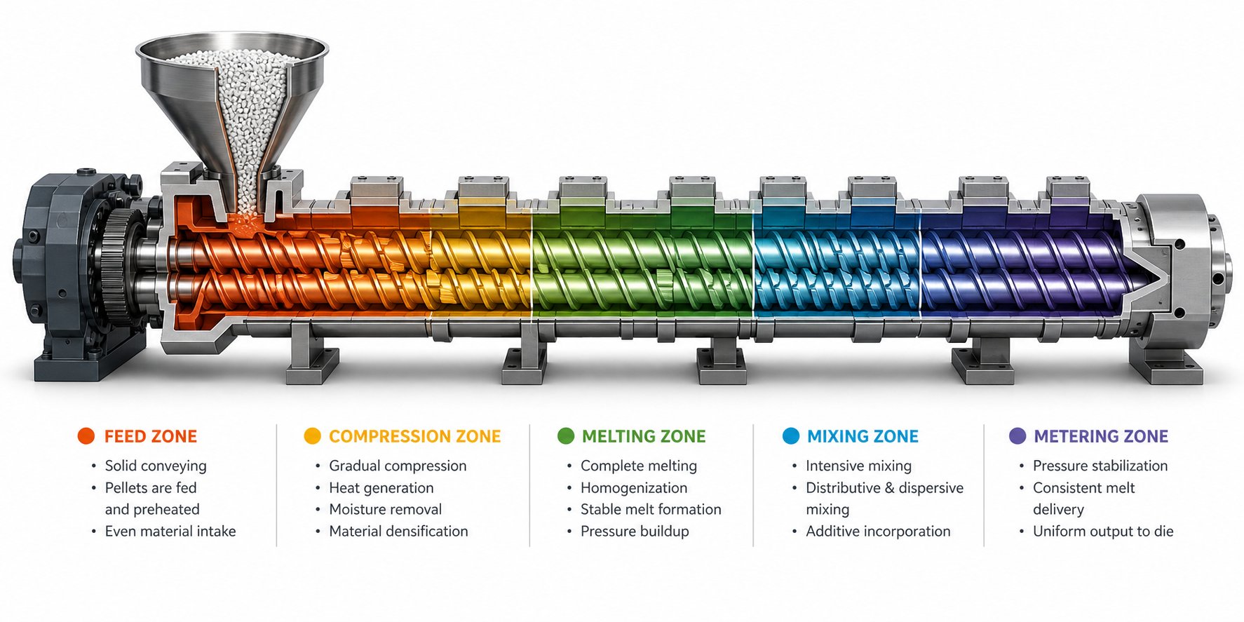
Picture the barrel of a co-rotating twin screw extruder as a timeline. Raw material enters at one end as solid pellets or powder and exits the other as a homogeneous, pressurized melt shaped by the die. Between those two points, the material undergoes a series of deliberate transformations, and each transformation corresponds to a functional zone defined by the screw elements occupying that section of the shaft.
Designing a profile from scratch means answering one question at each zone: which elements, in what order and pitch, will accomplish this zone's job without undermining the zones upstream or downstream? A twin screw zone-by-zone profile design methodology turns that question into a repeatable engineering process rather than trial-and-error guesswork.
Feed Zone Element Selection and Geometry Principles
The profile begins at the main feed port, and the goal here is simple: get material into the screws as fast and as consistently as the downstream process demands. Deep-flighted, wide-pitch conveying elements are the standard choice. Their generous channel volume maximizes solids intake and prevents material from backing up into the feed throat. A wider flight pitch, expressed as a ratio of pitch to screw diameter, translates directly into higher volumetric conveying capacity per revolution.
How you feed the extruder also shapes element selection. In starve-feeding mode, a gravimetric or volumetric feeder meters material at a rate below the screw's maximum conveying capacity, so the feed zone elements run partially filled. This approach gives you more precise control over fill level, shear history, and melting behavior downstream. Flood-feeding, by contrast, pushes material in as fast as the screws can accept it, filling the feed zone completely and relying on downstream restrictive elements to regulate throughput. Starve-feeding is far more common on co-rotating compounding extruders because it decouples throughput from screw speed, allowing independent optimization of each variable.
Melting and Plasticizing Zone Design Strategy
Solid polymer entering from the feed zone needs energy to transform into a processable melt. That energy comes from two sources: conductive heat transferred through the barrel wall and viscous dissipation generated by the screw elements themselves. The melting zone screw element strategy centers on transitioning from open conveying geometry to restrictive elements that force material into tighter flow channels, dramatically increasing shear and frictional heat input.
Kneading blocks are the workhorse here. Forward kneading elements initiate melting by compressing and shearing the solid bed against heated barrel surfaces, while their stagger angle controls how aggressively that energy is applied. A wider kneading disc promotes stronger dispersive action, while narrower discs offer gentler initial plasticization. The critical design decision is intensity: too little restriction and the material exits partially unmelted, too much and you overshoot your target melt temperature, risking thermal degradation. For heat-sensitive polymers, a gradual compression approach using progressively narrower pitch conveying elements before the first kneading block can soften the energy input curve significantly.
Venting and Devolatilization Zone Configuration
Many compounding and reactive extrusion processes require the removal of moisture, residual monomers, solvents, or reaction byproducts from the melt. This is accomplished through one or more vent ports along the barrel, and the screw profile in and around these ports follows strict design rules.
The devolatilization zone screw configuration starts with a melt seal positioned upstream of the vent opening. This seal, typically formed by reverse kneading blocks or reverse-threaded elements, creates a fully filled, zero-pressure transition that prevents melt from flowing backward into the vent port. Without a reliable melt seal, volatiles cannot be extracted under vacuum because melt would flood the vent, fouling equipment and ruining surface quality.
Downstream of the seal, large-pitch conveying elements occupy the vent zone itself. Their wide channels reduce the degree of fill, spreading the melt into thin layers with high surface area exposed to the low-pressure vent atmosphere. This surface renewal is the mechanism that drives volatile removal. The pitch must be large enough to relieve pressure effectively but not so large that material races through without adequate exposure time. When vacuum-assisted devolatilization is required, barrel vent inserts and vacuum pumps supplement the screw-driven surface renewal to pull volatiles out of the melt.
Pumping and Pressure Generation at the Die
At the far end of the barrel, the screw must deliver a stable, pressurized melt stream to the die. The pumping zone pressure generation in a twin screw relies on tight-pitch, forward-conveying elements with shallow channels. These elements restrict the flow cross-section, increasing fill level and building the back pressure necessary to push material through the die at a consistent rate.
Here is where upstream and downstream design interact most visibly. If the pumping zone generates excessive back pressure, the elevated pressure propagates upstream, increasing fill levels in zones that were designed to operate partially filled, particularly the vent zone. That back-pressure wave can compromise devolatilization efficiency or shift the melt seal position. Conversely, insufficient pressure generation causes surging at the die, producing inconsistent strand diameter or sheet thickness. Balancing the pumping zone with the rest of the profile often requires iterative adjustment, shortening or lengthening the tight-pitch section, or fine-tuning screw speed relative to feed rate.
The table below consolidates the core design logic for each functional zone, serving as a quick-reference framework when building or troubleshooting a profile:
| Zone Name | Primary Function | Typical Element Types | Key Design Considerations |
|---|---|---|---|
| Feed Zone | Solids intake and initial conveying | Deep-flighted, wide-pitch conveying elements | Maximize free volume; match element capacity to feed mode (starve vs. flood) |
| Melting / Plasticizing Zone | Convert solid to melt via shear and conduction | Forward kneading blocks, compression conveying elements | Control energy input intensity to hit target melt temperature without degradation |
| Mixing Zone | Dispersive and distributive homogenization | Kneading blocks (various stagger angles), gear-type mixing elements, toothed elements | Match mixing mode to additive type; position side feeders or liquid injection ports as needed |
| Venting / Devolatilization Zone | Remove volatiles, moisture, and reaction byproducts | Reverse elements or reverse kneading blocks (melt seal), large-pitch conveying elements (vent section) | Ensure reliable melt seal upstream; maximize melt surface renewal under low fill |
| Pumping / Pressure Zone | Build stable die pressure for consistent output | Tight-pitch, shallow-channel conveying elements | Balance back pressure against upstream zone fill requirements; avoid pressure-driven vent flooding |
Each zone in this framework handles a distinct material transformation, yet none operates in isolation. Pressure, fill level, and thermal history ripple across zone boundaries, which is exactly why the specific elements you place in each zone, and the angles and geometries of those elements, demand closer examination.
Screw Element Types and Sequencing Strategies
A twin screw profile is only as effective as the individual elements it contains and the order in which they appear. The zone-by-zone framework from the previous section tells you where each transformation should happen. This section tells you what goes in each location and why the arrangement changes depending on whether you are compounding mineral fillers, running a reactive extrusion, or stripping residual monomers.
Conveying Elements and Flight Pitch Variations
Conveying elements are the backbone of every profile. Their deeper flights enable efficient material transport to subsequent extruder sections without imparting significant shear or breaking down ingredients. The critical geometric variable is twin screw conveying element flight pitch, typically expressed as a ratio of pitch to screw diameter (P/D). A higher P/D ratio means the flight helix is more steeply angled, which increases the volumetric conveying rate per revolution and lowers the degree of fill at a given throughput. A lower P/D ratio compresses material into a tighter helix, slowing it down, increasing fill, and beginning to generate forward pressure.
Three functional variants cover most design needs:
- Standard-pitch (forward) elements — The general-purpose workhorse. Flight pitch roughly equals screw diameter (P/D ≈ 1.0). Used wherever material needs to move forward at a moderate fill level.
- Overflight (wide-pitch) elements — P/D ratios of 1.5 or higher. These maximize free volume in the feed zone and vent zone, keeping fill levels low for efficient solids intake or surface renewal during devolatilization.
- Reverse-pitch (left-hand) elements — Flights spiral in the opposite direction, pushing material backward. They create a retaining effect and upstream pressure buildup, functioning as melt seals before vent ports or as flow restrictors that increase residence time in an adjacent mixing section.
Imagine two conveying elements side by side: an SE-40/40 R and an SE-10/20 R. The first has a 40 mm pitch over a 40 mm length, generating strong forward conveying with minimal pressure buildup. The second packs a 10 mm pitch into 20 mm of length, dramatically increasing local fill and forward pressure. Simply swapping one for the other at a given barrel position shifts the entire pressure and fill profile downstream, which is why pitch selection in each zone is never arbitrary.
Specialized Mixing Elements for Advanced Processing
Kneading blocks handle much of the heavy lifting in mixing zones, but they are not always the best tool. When you need homogenization without the high shear stress that kneading discs impose, specialized mixing elements step in.
Gear-type fractional melt (GFM) elements use interlocking tooth geometries to repeatedly split and recombine the melt stream. Each tooth passage forces material through narrow channels that stretch and fold it, achieving excellent distributive mixing with relatively low shear stress. For shear-sensitive additives, color masterbatch, or long-fiber reinforcements that degrade under aggressive dispersive action, GFM elements outperform kneading blocks because they spatially randomize components without crushing them.
Toothed mixing elements (ZME) follow a similar philosophy. A study at Paderborn University using 3D CFD flow simulation with particle tracking demonstrated that toothed mixing elements achieved the best distributive mixing performance among all tested screw elements, consistently producing the lowest MQ index values (indicating the most uniform particle distribution). The same research found that ZME elements also generated high shear stresses across a broad, evenly distributed range, making them surprisingly effective for dispersive mixing as well. In practical terms, a ZME placed in the mixing zone delivers dual-mode performance: strong spatial redistribution paired with meaningful agglomerate breakup, all in a compact element length.
Other specialized geometries, such as screw mixing elements with interrupted flights and accumulation elements, fill niche roles. The key engineering judgment is straightforward: if the additive or polymer system cannot tolerate the intense, concentrated shear peaks generated in kneading block intermesh zones, a gear-type fractional melt element or toothed mixing element is the better choice.
Element Sequencing Logic for Compounding, Reactive Extrusion, and Devolatilization
Selecting the right elements is only half the challenge. Placing them in the correct sequence determines whether those elements actually deliver the intended processing result. Kneading block sequencing for compounding, for example, follows a fundamentally different logic than screw element sequencing for reactive extrusion, even though both processes may use many of the same individual components.
A general sequencing protocol applicable across most twin screw processes follows this progression:
- Begin with wide-pitch conveying elements at the feed port to maximize solids intake without backflow.
- Transition to progressively tighter-pitch conveying elements to increase fill and initiate compaction before the melting zone.
- Introduce forward kneading blocks to initiate melting through viscous dissipation, starting with narrow stagger angles and progressing to wider angles as the material softens.
- Place restrictive elements (neutral or reverse kneading blocks, or reverse-pitch conveying elements) to complete melting and create a melt seal if a downstream vent is required.
- Follow the melt seal with wide-pitch conveying elements through the vent zone to maximize surface renewal for devolatilization.
- Insert a second mixing section downstream of side feeders or liquid injection ports, using element types matched to the mixing mode required (dispersive for filler deagglomeration, distributive for sensitive additives).
- Close the profile with tight-pitch conveying elements to build die pressure for stable output.
How does this sequence shift across different applications? Consider three common scenarios:
- Compounding filled polymers: The mixing zone is dominated by wide-disc kneading blocks at aggressive stagger angles (60° and 90°) to break mineral filler agglomerates. A side feeder introduces filler downstream of the initial melting section so that abrasive particles contact only the melt, not the solid bed. Distributive elements like ZME or GFM segments follow to ensure uniform spatial distribution before the pumping zone.
- Reactive extrusion: Residence time control is paramount. Neutral kneading blocks and reverse elements are positioned to create multiple fully filled zones where reaction time can be precisely managed. Mixing intensity is moderate because the goal is intimate contact between reactants, not agglomerate breakup. Vent zones downstream strip reaction byproducts.
- Devolatilization of volatile monomers: The profile prioritizes surface renewal over mixing intensity. After a reliable melt seal formed by reverse kneading or reverse-pitch conveying elements, the vent zone is extended with wide-pitch conveying elements. Multiple vent stages, each preceded by its own melt seal, may be sequenced along the barrel for stepwise volatile removal.
Underlying all three scenarios is the behavior of material across five mass transfer regions present in the twin screw cross-section: the channel (bulk flow along the screw flight), extensional (stretching flow as material is pulled between lobal regions), overflight (thin-film shear in the gap between flight tip and barrel wall), apex (high-pressure zone at the leading edge of each flight), and intermesh (the region where material transfers between screws). Each element type and placement strategy alters how much time and energy the material experiences in these regions. Wide-pitch conveying elements keep material predominantly in the low-shear channel region. Kneading blocks force material through the high-stress intermesh, overflight, and extensional regions repeatedly. Toothed mixing elements create additional splitting and recombining pathways that amplify distributive action in the channel and extensional regions without the concentrated stress peaks found at the intermesh.
Understanding how each element shapes material behavior across these five regions is what separates a profile designed by principle from one assembled by habit. And among all the element variables available, none generates more debate, or more confusion, than kneading block stagger angle, which is precisely where the next section takes a deeper look.
Kneading Block Stagger Angles and Their Processing Effects
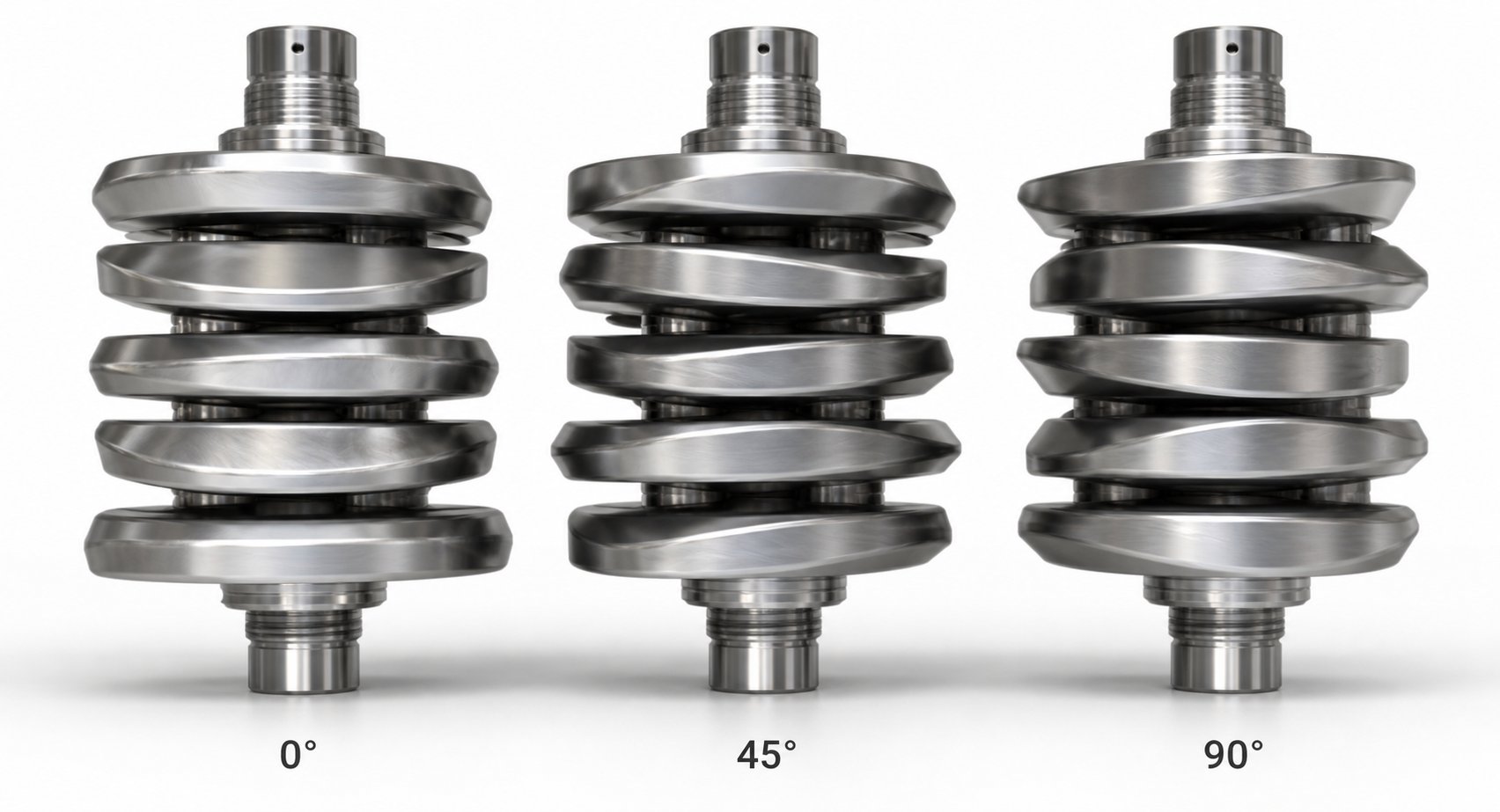
Every kneading block consists of a stack of elliptical discs mounted on the shaft, and every disc is rotated by a fixed angular offset from the one before it. That offset, the stagger angle, is deceptively simple. Change it by 30 degrees and you shift the balance between forward conveying and shear intensity in ways that ripple through your entire melt quality, temperature profile, and throughput stability. Yet most discussions of kneading block stagger angle effects stop at a surface-level overview. Here, you'll find the engineering detail needed for confident 30 60 90 degree kneading block selection in real production scenarios.
30-Degree Stagger Blocks for Gentle Forward Conveying and Mixing
When the angular offset between successive discs is narrow, each disc aligns closely with its neighbor. The result resembles an almost continuous helical flight, so the block pushes material forward with a strong conveying bias. A 30-degree kneading block provides minimal mixing while conveying material forward optimally, making it the gentlest option in the kneading block family.
What happens to the polymer inside? Because material spends relatively little time between the disc tips and the barrel wall, shear input stays low and melt temperature rise is modest. The dominant flow pattern is elongational: polymer stretches as it passes from one disc face to the next, rather than being compressed and sheared against the barrel. That elongational action provides enough energy to begin softening the solid bed without generating the high peak stresses that damage heat-sensitive polymers like PVC, EVOH, or certain bioplastics.
In a typical melting section, a 30-degree block is placed first in the kneading sequence. It pulls solid material from the upstream conveying elements into the melting zone and creates a smooth transition that minimizes backflow. Think of it as the on-ramp to high-intensity processing: it eases material in rather than slamming the brakes on forward flow.
60-Degree Stagger Blocks for Balanced Mixing Intensity
Widen the offset to 60 degrees and the processing character shifts significantly. The growing gap between disc faces forces more polymer over the disc tips instead of slipping smoothly along the helical path. That tip region, the narrow clearance between the disc edge and the barrel wall, is where shear rate peaks in any twin screw cross-section. As industry practitioners have documented, a 60-degree kneading block has poor forward-conveying capability but is much more efficient at mixing and imparts considerably more energy to the material.
The practical result is an intermediate behavior that balances three variables simultaneously: reduced forward conveying, increased local residence time in the kneading zone, and stronger dispersive action. Because more polymer is forced through the high-shear overflight gap, agglomerate breakup improves and melt homogeneity tightens. Kneading block mixing intensity in a twin screw peaks in this mid-range configuration for most general-purpose compounding tasks.
When is 60 degrees the default? For standard polyolefin or engineering plastic compounding where you need reliable melting and moderate filler dispersion without pushing melt temperature to the material's thermal limits, this angle represents the engineering sweet spot. It delivers meaningful work input while still conveying material forward, which is why you'll find 60-degree blocks as the backbone of melting sections across countless production profiles.
90-Degree Neutral and Reverse Kneading Blocks
Push the stagger angle to 90 degrees and forward conveying drops to essentially zero. A neutral kneading block neither pushes material downstream nor upstream. Instead, the polymer dwells in the block, repeatedly passing over disc tips and being sheared against the barrel wall. The fill level climbs to its maximum in this region because upstream conveying elements continue pushing material in while the neutral block provides no outlet. The result is the highest shear input and longest local residence time available in any forward-oriented kneading block configuration.
This makes 90-degree blocks powerful tools for two specific jobs. First, they provide the intense dispersive mixing needed to break tightly bonded agglomerates, whether you are dispersing carbon black, breaking mineral filler clusters, or ensuring complete melting of crystalline polymers with high melting points like nylon or PBT. Second, they act as a melt dam at the end of a melting section, restricting material flow to guarantee that every parcel of polymer passing downstream is fully molten.
Reverse-staggered kneading blocks go a step further. By offsetting the discs in the opposite rotational direction, the block actively pushes material backward. This creates a localized high-fill zone that dramatically increases residence time and mixing intensity beyond what a neutral block achieves. In reverse kneading block melt seal design, these elements are placed immediately upstream of vent ports to form a gas-tight pressure barrier. Without that barrier, vacuum applied at the vent would pull air backward through the barrel rather than extracting volatiles from the melt surface. The reverse block's ability to generate upstream pressure makes it indispensable for devolatilization zone sealing and for high-intensity mixing of difficult compounds.
One variable interacts closely with stagger angle and deserves mention: disc width. Wider discs force more polymer over the tip clearance, acting like a plow, while narrower discs slice through the melt with less energy input. A five-disc kneading block at 60 degrees with wide paddles generates significantly more shear than a seven-disc block at the same angle with narrow paddles. Engineers evaluate both parameters together when fine-tuning a profile.
The table below consolidates all primary kneading block configurations into a side-by-side comparison:
| Stagger Angle | Conveying Bias | Mixing Intensity | Shear Level | Typical Application |
|---|---|---|---|---|
| 30° forward | Strong forward | Low | Low | Gentle initial melting; transition from conveying to kneading; heat-sensitive polymers (PVC, EVOH) |
| 45° forward | Moderate forward | Low to moderate | Moderate | General-purpose melting; moderate mixing where less energy input is acceptable |
| 60° forward | Weak forward | Moderate to high | High | Intensive melting; dispersive mixing of fillers and pigments; standard compounding backbone |
| 90° neutral | None (zero net conveying) | High | Very high | Maximum shear dispersion; melt dam for complete melting; melt homogenization |
| Reverse (left-handed) | Negative (pushes backward) | Very high | Very high | Melt sealing upstream of vent ports; high-intensity mixing of difficult or crystalline compounds |
The progressive shear ramp, arranging blocks in ascending stagger order from 30 degrees through 60 to 90, is one of the most widely adopted design strategies in the industry. It eases material into increasingly aggressive mixing, protects feed stability, and ensures complete melting before the melt exits the plasticizing zone. Yet stagger angle only defines how hard the material is worked. The equally critical question of what kind of mixing that work produces, dispersive versus distributive, demands its own framework.
Distributive vs Dispersive Mixing Through Element Design
Shear intensity tells you how aggressively an element works the melt, but it does not tell you what that work accomplishes. A kneading block can deliver enormous energy input and still produce a poorly mixed compound if the mixing mode does not match the material challenge. That distinction, the difference between distributive and dispersive mixing in a twin screw, is what separates a technically correct profile from one that actually solves the problem on the production floor.
The framework is straightforward. Dispersive mixing breaks things apart. It applies high stress fields, both shear and elongational, to fracture agglomerates, reduce domain size in polymer blends, and rupture cohesive particle clusters down to their fundamental aggregate size. Distributive mixing, by contrast, spreads things around. It spatially randomizes already-small components throughout the polymer matrix through repeated splitting, folding, and recombining of the melt stream, all without requiring high stress.
A compound can be dispersed but not distributed, meaning particles are broken to their ultimate size but concentrated in one region of the matrix. It can also be distributed but not dispersed, with large agglomerates spread evenly throughout the polymer but never broken down. As industry expert Kenneth Russell explains, you need both dispersive and distributive mixing to produce a truly homogeneous compound, and the screw profile must deliver each mode deliberately through specific element geometries.
How Specific Element Geometries Achieve Dispersive Mixing
Dispersive mixing screw element geometry centers on one physical principle: forcing material through regions of concentrated stress. In a co-rotating twin screw extruder, the highest stress fields occur in the intermesh zone, where material transfers between screws, and in the overflight gap between disc tips and the barrel wall. Wide-disc kneading blocks at 60-degree and 90-degree stagger angles exploit both regions aggressively.
Imagine a wide kneading disc rotating through the melt. It acts like a plow, forming a pool of molten polymer ahead of the disc face and then smearing that material through the narrow tip clearance. The compressive and extensional flow fields generated during this process are exactly what is needed to fracture agglomerates. The wider the disc, the larger the melt pool and the more intense the plowing action. A narrow disc, by contrast, slices through the polymer rather than plowing it, generating far less dispersive force.
Combine wide discs with a high stagger angle, say 60 or 90 degrees, and you get maximum fill in the kneading zone with the longest exposure time in those high-stress regions. This is why dispersing carbon black, a notoriously cohesive material whose aggregates are held together by weak van der Waals forces, demands wide-disc kneading blocks at aggressive stagger angles. The same logic applies to breaking down mineral filler clusters like calcium carbonate or talc agglomerates: you need enough stress magnitude and enough exposure time to overcome the cohesive forces binding those particles together.
3D CFD simulation research at Paderborn University confirms this at the particle level. Their analysis showed that kneading blocks with 45-degree stagger angles generate a broader range of high shear stresses compared to 90-degree blocks with shorter disc widths (KB12), and that higher rotational speeds push the shear stress distribution further into ranges capable of breaking agglomerates. Interestingly, the same study found that toothed mixing elements (ZME) produced the widest and most uniform distribution of high shear stresses across all particles, meaning more material actually experiences the stress levels needed for effective dispersion, not just the material passing through the peak shear zones.
Distributive Mixing Elements and Low-Shear Homogenization
Not every additive needs to be crushed. Color masterbatch pellets, for example, are already formulated at the correct particle size. Long glass fibers lose their reinforcing value if sheared aggressively. Shear-sensitive stabilizers or reactive additives can degrade under the stress fields that kneading blocks generate. For these materials, the goal is spatial redistribution, not particle size reduction, and that calls for low-shear distributive mixing elements.
Narrow-disc kneading blocks are the simplest entry point. By slimming the disc width, you change the dominant flow pattern from plowing to slicing: the polymer divides around each thin disc and recombines on the other side, creating a scissoring action that stirs the melt without concentrating stress. Forward-conveying narrow-disc blocks at moderate stagger angles (30 to 45 degrees) provide gentle homogenization that is well suited for final color incorporation or blending of pre-dispersed additives.
Gear-type fractional melt (GFM) elements and toothed mixing elements take distributive performance a step further. Their geometries force the melt stream through multiple narrow channels, splitting and recombining it dozens of times within a short element length. Each split-and-recombine cycle doubles the interfacial area between components, rapidly improving spatial uniformity. The Paderborn study referenced earlier demonstrated that the ZME consistently achieved the lowest mixing index (MQ) values among all tested screw elements, meaning the most uniform particle distribution in the cross-sectional plane, outperforming even the longer kneading blocks designed for the same purpose.
When should you reach for these elements instead of kneading blocks? The decision points are clear:
- Long-fiber reinforcements (glass, carbon, natural fibers): fiber length preservation requires low shear; GFM or toothed elements distribute fibers without breaking them.
- Color masterbatch: pigment is already dispersed at manufacture; you only need uniform spatial distribution through gentle folding action.
- Shear-sensitive additives: antioxidants, UV stabilizers, or reactive coupling agents that degrade under high stress are better served by distributive elements placed downstream.
- Polymer blends with large viscosity ratios: extensional flow in toothed elements can deform the minor phase more effectively than the simple shear dominated by kneading blocks.
Balancing Both Mixing Modes in a Single Profile
Real-world compounding rarely requires only one mixing mode. A glass-fiber-reinforced polypropylene with carbon black pigment, for instance, needs aggressive dispersion to break carbon black agglomerates and gentle distribution to preserve fiber length, both within the same screw profile. How do you reconcile those opposing demands?
The answer is staging. A well-designed profile typically positions dispersive mixing upstream, closer to the melting zone, where material is more robust and can tolerate higher stress without damage. Wide-disc kneading blocks at 60 and 90 degrees handle agglomerate breakup here. Downstream, after side feeding of shear-sensitive components, the profile transitions to distributive elements: narrow-disc kneading blocks, GFM segments, or toothed mixing elements that homogenize the compound without degrading the additives just introduced.
Kenneth Russell, a veteran of more than 35 years in polymer processing, emphasizes a practical nuance in his series on twin screw extruder configuration: mixing sections work more efficiently and more gently when they operate at a higher degree of fill, but this must be balanced against overly restrictive elements that overwork the material. Ending a mixing section with a neutral or reverse kneading block ensures sufficient fill for effective mixing while preventing the empty-channel "whipping" that can spike melt temperature and damage fiber aspect ratio.
Mixing mode selection for polymer compounding is dictated by material rheology and additive morphology, not by a universal rule. The stress threshold needed to break a carbon black agglomerate is fundamentally different from the gentle folding needed to distribute a pre-dispersed color concentrate, and the screw profile must reflect that difference through deliberate element geometry choices in each mixing zone.
This principle explains why two profiles designed for the same base polymer can look entirely different: the additives define the mixing requirement, and the mixing requirement defines the elements. Yet even the most carefully selected geometry will underperform if the element itself degrades prematurely under abrasive or corrosive conditions, which is why the metallurgy behind each screw element deserves the same engineering attention as its shape.
Screw Element Metallurgy and Wear Resistance Considerations
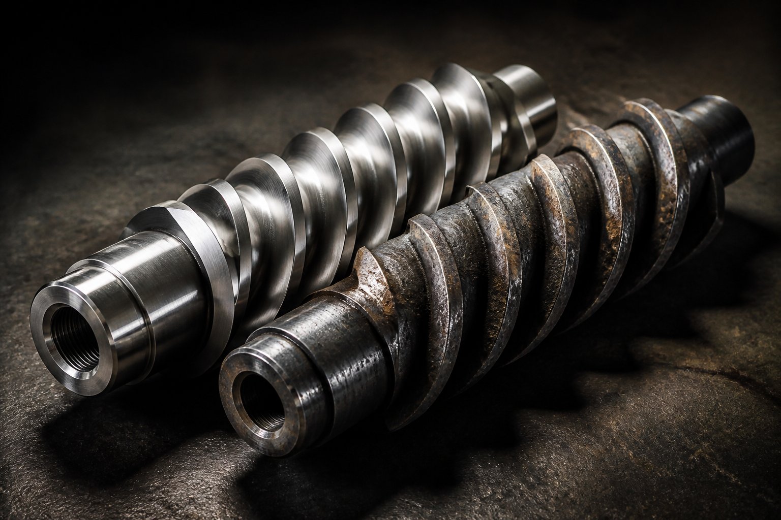
A perfectly sequenced screw profile with optimized stagger angles and ideal mixing modes can still fail spectacularly if the elements themselves erode, pit, or corrode within weeks of installation. Screw element metallurgy for twin extruders is often treated as an afterthought, something the purchasing department handles once the engineer specifies geometry. That approach is costly. In abrasive formulations like glass-fiber-reinforced polyamide at 40% loading, or corrosive environments like fluoropolymer processing, element material selection directly determines whether your profile delivers consistent results for months or degrades into a maintenance headache within a single production campaign.
The core principle is simple: geometry defines what the element does; metallurgy defines how long it keeps doing it. Both deserve equal engineering attention.
Common Metallurgies for Screw Elements and Their Trade-Offs
Twin screw elements are manufactured from several material families, each engineered for different combinations of hardness, toughness, and chemical resistance. Choosing among them requires matching the alloy to the specific wear and corrosion environment your process creates. Here are the primary categories and their use cases:
- Nitrided steels (e.g., 38CrMoAlA) — The entry-level standard. Gas nitriding produces a hard surface layer that resists mild abrasion at a relatively low cost. Suitable for unfilled or lightly filled polyolefins, ABS, and general-purpose compounding where filler content stays below roughly 20% and no corrosive additives are present. Good machinability makes these elements easy to produce, but their wear resistance falls short under demanding conditions.
- Tool steels and high-speed steels (e.g., Cr12MoV, M2-type grades) — Higher carbon and alloy content deliver greater matrix hardness through quenching and tempering. These materials maintain hardness at elevated temperatures and handle moderate abrasion from mineral fillers like calcium carbonate or talc at intermediate loadings. They represent a meaningful step up from nitrided steel without the cost premium of powder metallurgy grades.
- Powder metallurgy alloy screw elements (PM-HIP grades, including WR-series and CPM-series alloys) — Manufactured by hot isostatic pressing of pre-alloyed powders, these materials contain extremely uniform distributions of hard carbide phases (vanadium carbide, tungsten carbide) throughout the matrix. The result is exceptional wear resistance combined with toughness that conventional cast or wrought steels cannot match. These are the go-to choice for high-abrasion environments: glass-fiber-filled compounds at 30%+ loading, highly filled mineral systems, and carbon-black-intensive formulations.
- Nickel-based corrosion-resistant alloys — High concentrations of nickel, chromium, and molybdenum form a dense passivation layer that resists chemical attack from acids, halogens, and reactive decomposition products. Essential for processing fluoropolymers (PTFE, FEP, PVDF), halogenated flame retardants, and certain reactive extrusion chemistries where corrosive byproducts are generated at melt temperatures.
Cost scales roughly in the order listed, with nitrided steels at the low end and nickel-based alloys at the premium. However, total cost of ownership often inverts that ranking. A set of inexpensive nitrided steel elements that wears out every three months costs more in downtime, replacement parts, and quality deviations than a set of PM-HIP elements that runs for two years under the same conditions.
Wear Mechanisms That Drive Material Selection
Selecting the right wear resistant screw element materials requires understanding how your process attacks the metal. Three primary degradation mechanisms dominate, and each responds to different metallurgical strategies:
Abrasive wear occurs when hard particles, glass fibers, mineral fillers, or even unmelted polymer granules, slide across the element surface and mechanically remove material. Imagine glass fiber tips dragging across a screw flight like sandpaper on wood. The harder and more uniformly distributed the carbide phases in the element matrix, the better the surface resists this micro-cutting action. This is precisely why abrasive wear screw element selection overwhelmingly favors PM-HIP alloys for high-filler formulations: their dense carbide networks create a surface that hard particles cannot easily gouge.
Adhesive wear arises when metal-to-metal contact occurs between screw elements and the barrel wall or between the intermeshing surfaces of the two screws. Under high pressure and temperature, micro-welds form and tear apart at the contact points, pulling material from one surface onto the other. This mechanism is most damaging in tight-clearance regions, exactly where kneading blocks and pumping elements operate. Proper clearance specification and surface hardness compatibility between screw elements and barrel liner reduce adhesive wear, but the fundamental defense is ensuring barrel and screw metallurgies are not identical, which prevents the cold-welding tendency of matched metal pairs.
Corrosive wear is chemically driven. Decomposition byproducts from fluoropolymers release hydrofluoric acid; halogenated flame retardants generate hydrochloric acid; certain reactive extrusion chemistries produce organic acids or free radicals that attack carbon steel matrices. No amount of hardness helps when the surface is being dissolved. The only effective defense is a passivating alloy, typically nickel-chromium-molybdenum based, that forms a chemically inert barrier between the process stream and the structural metal underneath.
In many real-world processes, these mechanisms overlap. Glass-fiber-reinforced nylon with brominated flame retardant, for example, delivers simultaneous abrasive and corrosive attack, demanding elements that combine high carbide content with corrosion-resistant matrix chemistry. These dual-threat formulations represent some of the most challenging applications in twin extruder screw design and often push engineers toward the most advanced (and most expensive) material solutions available.
Matching Element Materials to Processing Demands
There is no universal "best" screw element material, only the best material for a specific set of operating conditions. The selection process must account for several interacting variables:
- Polymer system: Is the base resin chemically aggressive at processing temperature? Fluoropolymers and chlorinated PVC demand corrosion-resistant alloys; polyolefins and ABS are chemically benign.
- Filler type and loading level: Glass fiber at 50% loading is exponentially more abrasive than calcium carbonate at 20%. The filler's Mohs hardness and particle morphology (sharp edges vs. rounded) directly determine how quickly it erodes element surfaces.
- Processing temperature: Higher temperatures accelerate corrosive reactions and can soften certain tool steels below their effective hardness threshold. PM-HIP alloys retain hardness at elevated temperatures far better than conventional heat-treated steels.
- Expected production volume: A short-run specialty compound may justify lower-cost nitrided steel elements with planned replacement intervals, while a 24/7 commodity compounding line needs maximum wear life to minimize unplanned downtime.
Surface hardening technologies add another layer of flexibility. Gas nitriding, HVOF (high-velocity oxy-fuel) thermal spraying, and bimetallic cladding can all enhance base material performance. HVOF spraying, for instance, deposits a wear-resistant alloy layer onto the element surface, boosting abrasion and corrosion resistance for demanding systems involving glass fiber, carbon black, or flame retardants. These coatings extend element life without requiring a full upgrade to premium base materials, offering a practical middle ground for budget-constrained operations.
This is an area where incorrect decisions carry disproportionate consequences. Choosing an element material that underperforms leads to dimensional changes that alter clearances, degrade mixing performance, and introduce metal contamination into the product stream, sometimes before the wear is visually obvious. By the time an operator notices performance drift, the profile geometry has already changed from what the engineer originally designed. For engineers navigating complex metallurgy decisions, especially in multi-filler or corrosive systems, specialist consultation can prevent costly missteps. Services like NANHAIYA's Custom Screw Design Services provide material selection recommendations tailored to specific polymers, filler systems, and machine conditions, pairing metallurgical expertise with application knowledge that general material data sheets alone cannot deliver.
Getting the metallurgy right ensures that the carefully designed geometry you specified in your profile actually persists through thousands of production hours. Yet even with the ideal elements in the ideal materials, predicting how a new profile will perform before cutting metal or placing an order requires a different kind of tool entirely: computational simulation.
Computational Simulation and Process Modeling for Screw Design
You have selected your elements, specified stagger angles, staged your mixing modes, and matched your metallurgy to the process environment. The profile looks sound on paper. But how do you know it will actually work before committing to a production trial that consumes raw material, machine time, and engineering hours? This is where computational simulation enters the picture, offering a way to test screw profile hypotheses digitally before a single pellet hits the feed throat.
Modern twin screw extrusion simulation software has matured significantly, yet it remains surprisingly underutilized in many compounding operations. Part of the reason is that engineers are unsure which tool fits which question. Three distinct simulation categories exist, each suited to a different slice of the design problem, and understanding their strengths and blind spots is essential for extracting real value from any modeling effort.
CFD, DEM, and 1D Process Simulation Explained
Computational Fluid Dynamics (CFD) delivers the highest resolution view of what happens inside individual screw elements. By solving the Navier-Stokes equations across a meshed 3D geometry, CFD modeling for screw element design reveals velocity fields, shear rate distributions, pressure gradients, and temperature profiles at every point in the flow domain. Want to know exactly how a 60-degree kneading block generates extensional stress in the intermesh region, or how a toothed mixing element splits and recombines the melt stream? CFD provides that answer. A comprehensive literature review published in Fluids documents how CFD models have evolved from simplified flat-plate approximations to full 3D helical geometries, enabling researchers to quantify both dispersive and distributive mixing through metrics like residence time distribution, shear stress integrals, and particle tracking.
The practical limitation? CFD is computationally expensive. Simulating even a short section of screw, say two or three element lengths, with non-Newtonian rheology, thermal coupling, and adequate mesh resolution can require hours or days of compute time. Modeling a full-length extruder barrel at CFD resolution remains impractical for routine design iterations. This makes CFD ideal for deep-diving into specific element interactions but poorly suited for evaluating an entire profile end-to-end.
Discrete Element Method (DEM) addresses a different phase of the problem entirely: solids conveying. In the feed zone, polymer pellets, powder, or granules are not yet melted, so continuum-based CFD assumptions break down. DEM treats each solid particle as an individual body governed by contact mechanics, friction, and gravity. It predicts how pellets flow into the screw flights, how they pack and compact under conveying element geometry, and where bridging or flooding issues might occur. Researchers have proposed coupled DEM/CFD global models that hand off results from the solid-conveying DEM simulation to a melt-phase CFD simulation at the point where melting begins, providing a more complete picture of the entire extrusion process without segmenting it into disconnected zones.
1D process simulation is the workhorse for full-profile evaluation. Rather than resolving detailed 3D flow fields, these tools treat the extruder as a sequence of discrete axial segments. At each segment, simplified analytical or semi-empirical models predict temperature, pressure, fill level, specific energy input, and residence time based on the element geometry, operating conditions, and material properties you specify. The result is a complete axial profile of process conditions from hopper to die, generated in minutes rather than days.
Think of 1D process simulation for a twin screw extruder as the "weather forecast" for your profile: it tells you the overall temperature trend, where pressure peaks occur, which zones run partially filled, and whether your total residence time falls within the window your chemistry requires. It does not tell you the exact flow pattern inside a single kneading block, but it does tell you whether that block is likely to overheat your polymer or starve your vent zone of fill. For engineers iterating through multiple profile configurations before selecting a final candidate, 1D simulation is the most practical starting point.
Simulation Limitations and the Role of Empirical Validation
Sounds like simulation could replace trial runs entirely? Not quite. Every modeling approach carries limitations that experienced engineers must account for.
CFD struggles with complex multi-phase systems. Real compounding involves solid pellets, molten polymer, dispersed fillers, entrained air, and sometimes volatile gases, all coexisting and interacting. Modeling these multi-phase flows accurately requires interface tracking, phase-change algorithms, and reaction kinetics that push computational demands into territory that remains, as the Fluids review notes, one of the most significant challenges in reactive extrusion CFD. Even advanced methods like Smoothed Particle Hydrodynamics (SPH), which have been successfully applied to partially filled twin screw flows, face difficulties when chemical reactions, gas generation, and particle formation occur simultaneously.
Material property databases represent another bottleneck. Every simulation is only as good as the rheological data you feed it. Viscosity as a function of shear rate and temperature, thermal conductivity, heat capacity, and density at processing conditions must all be accurately characterized. For commodity resins like polyethylene or polypropylene, reliable data is widely available. For specialty compounds, reactive systems, or highly filled formulations, obtaining accurate property data may require dedicated rheometry testing, and even small errors in viscosity models propagate through the entire simulation.
Wear and degradation prediction sits almost entirely outside the scope of current simulation tools. No commercially available twin screw simulation software predicts how quickly a kneading block will erode under glass-fiber abrasion or how polymer degradation products will corrode element surfaces over time. These phenomena depend on metallurgical interactions, particle impact dynamics, and chemical kinetics that remain beyond the reach of flow-focused models. The metallurgical considerations discussed in the previous section still rely heavily on empirical experience and materials testing.
The practical takeaway? Simulation narrows the design space. It eliminates obviously poor configurations, identifies potential thermal or pressure problems before they destroy product, and reduces the number of physical trials needed from dozens to a handful. It does not, however, deliver a final, production-ready profile without at least one round of empirical validation on the actual machine.
L/D Ratio and Its Impact on Simulation and Design
One parameter threads through every simulation input screen and every profile design conversation: the length-to-diameter ratio, or L/D. This single number defines the playing field for your entire screw configuration.
The L/D ratio impact on twin screw design is direct and multidimensional. A longer barrel relative to screw diameter means more axial space for functional zones: more room for melting, multiple mixing sections, extended vent stages, and a dedicated pumping section. A typical co-rotating compounding extruder operates between 32:1 and 48:1 L/D, though specialized reactive extrusion and devolatilization machines can push beyond 52:1 to accommodate the additional residence time and zone count those processes demand.
From a simulation perspective, L/D serves as the primary geometric input that determines how many discrete elements can be accommodated and how the axial profile of temperature, pressure, and fill distributes across the barrel. In 1D process models, you define each element's position along the L/D axis, and the simulator calculates cumulative energy input, melt temperature evolution, and pressure buildup at every point. Changing the L/D ratio does not just scale the barrel; it changes the number of processing zones you can fit, which in turn changes the profile strategy itself. A 32:1 machine forces compromises: you might need a single vent stage where two would be ideal, or a shorter mixing section than the filler loading demands. A 48:1 machine gives breathing room but adds cost, torque requirements, and potential for excessive residence time that can degrade heat-sensitive polymers.
Residence time and throughput capacity both scale with L/D, but not linearly. Doubling barrel length at constant screw speed roughly doubles the mean residence time, but the distribution of that residence time depends on fill level, which is itself a function of element pitch, throughput, and screw speed. Simulation tools capture these interactions far more reliably than hand calculations, which is precisely why L/D selection and profile design should be evaluated together rather than treated as independent decisions.
Simulation is most valuable for narrowing the design space before committing to physical trials. It transforms screw profile design from an open-ended trial-and-error exercise into a structured optimization process where each physical run tests a refined hypothesis rather than an educated guess.
Even the most sophisticated simulation, however, models a single machine at a single scale. The moment you need to transfer a proven lab-scale profile to a production extruder with a different diameter, different L/D, and different thermal mass, a new set of engineering challenges emerges, challenges that simulation alone cannot fully resolve.
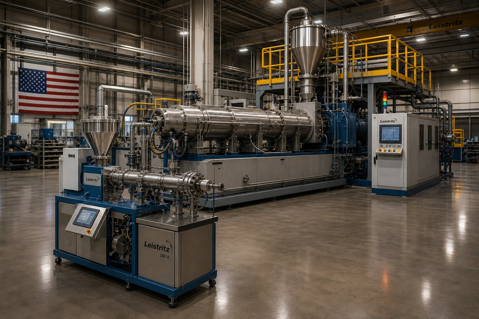
Application-Specific Twin Screw Profile Design and Scale-Up Strategy
A screw profile that produces flawless polypropylene compound on a 26 mm lab extruder may deliver unmolten pellets, phase separation, or thermal degradation when transferred to a 92 mm production machine. And a profile optimized for polymer compounding will fail spectacularly if applied unchanged to pharmaceutical hot-melt extrusion or food-grade starch processing. These are not theoretical risks. They are the two most common failure modes engineers face once the fundamentals of element selection and sequencing are in hand: adapting a profile to a different application and scaling it to a different machine size.
Both challenges share a root cause. The zone-by-zone design methodology covered earlier in this article is universal, but the specific priorities within each zone shift dramatically depending on the material system, the industry, and the physical scale of the extruder. Understanding how those priorities shift is what separates a profile that works in principle from one that works in production.
Adapting Screw Profiles Across Polymer, Food, and Pharmaceutical Applications
Imagine three engineers, each sitting in front of an identical co-rotating twin screw extruder. One is compounding 40% glass-fiber-reinforced nylon. The second is processing a corn-starch-based snack. The third is producing a hot-melt extruded pharmaceutical tablet containing an active pharmaceutical ingredient (API) with a narrow thermal stability window. All three will use conveying elements, kneading blocks, and mixing sections. None of them will arrange those elements the same way.
Polymer compounding demands high dispersive mixing for fillers and pigments. The screw profile prioritizes aggressive kneading blocks at 60- and 90-degree stagger angles to break agglomerates, side-feed ports positioned downstream of the melting zone to protect abrasive fillers from the solid-bed compression region, and extended mixing sections that ensure uniform filler distribution before the pumping zone. L/D ratios of 40:1 to 48:1 are standard because multiple mixing and venting stages must fit along the barrel. Melt temperature control matters, but throughput and dispersion quality typically take precedence.
Food extrusion flips several of those priorities. Starch conversion, the transformation of raw starch granules into a cooked, expanded, and texturized product, depends on controlled thermal-mechanical energy input. Too little energy and the starch remains undercooked; too much and the product loses texture, color, or nutritional value. Screw profile design in food extrusion is described as a blend of art and science precisely because the flow properties of food-grade materials vary enormously with moisture, fat content, and protein composition. The profile typically uses moderate-intensity kneading sections to generate enough shear for gelatinization without burning the product, and shorter L/D ratios (20:1 to 32:1) because the residence time window for proper cooking is narrower than in polymer systems. Reverse elements serve as cooking dams rather than melt seals, holding material in high-temperature zones long enough for starch conversion to complete.
Pharmaceutical extrusion introduces the most stringent constraints of all. Hot-melt extrusion (HME) for drug delivery requires a narrow residence time distribution to ensure every particle of API experiences identical thermal history. Wide variation in residence time means some API degrades from overexposure while other material passes through underprocessed. The profile favors gentle, distributive mixing elements that homogenize the drug-polymer matrix without generating high shear peaks that can degrade thermally sensitive APIs. Pharmaceutical extrusion screw design considerations also include cleanability, the ability to disassemble, inspect, and validate every element surface for cross-contamination compliance, which favors shorter profiles at 20:1 to 30:1 L/D with fewer total elements.
| Application Type | Primary Design Priority | Typical L/D Range | Critical Element Choices |
|---|---|---|---|
| Polymer compounding | Dispersive filler mixing and deagglomeration | 40:1 to 48:1 | Wide-disc kneading blocks (60°, 90°); side-feed conveying sections; multi-stage venting; reverse elements for melt seals |
| Food extrusion | Controlled thermal-mechanical energy for starch conversion | 20:1 to 32:1 | Moderate-intensity kneading sections; reverse elements as cooking dams; wide-pitch conveying in moisture-sensitive zones |
| Pharmaceutical processing (HME) | Narrow residence time distribution for API stability | 20:1 to 30:1 | Distributive mixing elements (GFM, narrow-disc kneading); minimal reverse elements; gentle forward-conveying profile |
The table makes one point unmistakably clear: application-specific twin screw profile design is not about choosing different elements from a catalog. It is about reprioritizing the same fundamental design variables, mixing intensity, residence time, energy input, and pressure generation, to serve fundamentally different material transformation goals. A profile that excels at glass-fiber dispersion would destroy an API, and a gentle pharmaceutical profile would leave mineral fillers in agglomerated clumps.
Scale-Up Principles from Laboratory to Production Extruders
Even within a single application, transferring a proven profile from a small machine to a larger one introduces challenges that catch experienced engineers off guard. The core difficulty is deceptively simple: geometric similarity does not guarantee process similarity. You can replicate every element type, every stagger angle, and every pitch ratio on a larger extruder and still get a completely different product.
Why? Three interrelated factors change as diameter increases:
- Specific energy input shifts. The primary energy source in a twin screw extruder is mechanical energy transferred from the screws into the melt through shear. A case study scaling from 26 mm to 92 mm extruders demonstrated this vividly: when identical screw design, temperature profile, and screw speed were applied to the 92 mm machine, specific mechanical energy (SME) dropped by 69% compared to the lab-scale process, resulting in unmolten pellets discharging through the die. The process only stabilized when screw design and feeding configuration were modified to restore the target SME of approximately 0.083 kWh/kg.
- Surface-to-volume ratio decreases. Volume grows by the cube of the diameter ratio while surface area only grows by the square, meaning heat transfer through the barrel wall becomes increasingly inefficient as the machine gets larger. A small lab extruder can effectively heat or cool the melt through the barrel; a production machine relies almost entirely on viscous dissipation from the screws for energy input. This thermal shift means that barrel temperature setpoints that worked perfectly at lab scale may have negligible effect at production scale.
- Residence time distribution changes. Larger free volume in bigger machines, combined with altered fill levels, broadens the residence time distribution unless feed rate and screw speed are specifically adjusted. The same Thermo Fisher scale-up study found that residence time is a critical process parameter for scale-up and that the theoretical throughput factor predicted by the Schuler rule (cube of diameter ratio) required empirical correction: the 16 mm machine needed a feed rate adjustment from the predicted 3 kg/h down to 2.5 kg/h to match the specific energy and residence time measured on the 11 mm extruder.
The Plastics Technology case study by Dow research scientist Carlos Escobar illustrates a practical lab to production extruder screw scale-up workflow. The team used geometrically similar co-rotating extruders at 26 mm, 40 mm, and 92 mm (all at 44:1 L/D with identical OD/ID ratios of 1.55). At each scale transition, the initial attempt used identical process conditions from the smaller machine with throughput scaled by the volumetric ratio. At both the 40 mm and 92 mm scales, this approach failed: pressure instabilities, phase separation, and poor mixing required adjustments to screw design, temperature profile, and screw speed. The consistent finding was that matching SME across scales, not merely replicating screw geometry, was the key to achieving equivalent product quality.
Twin screw extruder scale-up principles, then, come down to a hierarchy of matching priorities:
- Maintain equivalent specific mechanical energy (kWh/kg) as the primary target.
- Match residence time and residence time distribution by adjusting feed rate relative to the volumetric scale-up prediction.
- Accept that screw profiles will likely require modification: more aggressive melting sections to compensate for reduced barrel heat transfer, adjusted kneading block configurations to restore shear intensity, or modified pumping zones to handle different pressure-flow characteristics at the larger scale.
- Validate through empirical trials, using residence time measurement (preferably via tracer-based distribution analysis) to confirm that the scaled process actually replicates the thermal and mechanical history of the lab-scale baseline.
The scale-up challenge is particularly acute when moving across more than one size increment. Escobar's work showed that a raw material creating a lubricating effect along screws and barrels was manageable on the 40 mm machine but caused complete process failure on the 92 mm unit. The root cause, the dramatically lower area-to-volume ratio at the larger scale, meant that the lubricated surfaces could not transfer enough shear energy into the material. Only a redesigned screw profile with increased melting and mixing intensity resolved the problem. This kind of scale-dependent behavior is impossible to predict from geometry alone and reinforces why physical validation at each scale remains non-negotiable.
When to Engage Custom Screw Design Expertise
The principles covered throughout this article, zone-by-zone design, element sequencing, stagger angle selection, mixing mode staging, metallurgy, simulation, and scale-up, provide a robust framework for any process engineer working with twin screw extruders. But frameworks describe the decision space; they do not make the decisions for you.
Certain situations push beyond what general-purpose screw configurations and textbook principles can resolve on their own:
- Novel polymer systems with limited published rheological data, where simulation inputs are uncertain and trial-and-error iteration on production equipment is prohibitively expensive
- Multi-filler formulations combining abrasive, corrosive, and shear-sensitive components in the same compound, requiring simultaneous optimization of metallurgy, mixing mode, and element sequencing
- Scale-up transitions spanning more than one machine size increment, where surface-to-volume effects and SME matching interact unpredictably
- Industry-specific compliance requirements, such as pharmaceutical cleanability validation or food-contact material traceability, that constrain element geometry and material choices beyond purely process-driven optimization
In these scenarios, specialist consultation accelerates the path from concept to validated production. Services like NANHAIYA's Custom Screw Design Services offer screw geometry, material selection, and processing recommendations tailored to specific polymers, machine conditions, and output requirements, bridging the gap between universal design principles and the application-specific solutions that real production demands. For engineers who have absorbed the frameworks in this article and need to translate them into a profile that performs on a particular machine, with a particular resin, at a particular scale, that kind of targeted expertise is often the most efficient next step.
Twin extruder screw design is ultimately an iterative discipline. No single article, simulation tool, or design service eliminates the need for informed engineering judgment. What they collectively provide is a structured path: from understanding the physics, to specifying the elements, to validating the profile, and, finally, to producing a compound that meets specification, run after run, at any scale.
Frequently Asked Questions About Twin Extruder Screw Design
1. What are the main types of screw elements used in twin extruder screw design?
Three primary categories form every twin screw profile. Conveying elements use helical flights at varying pitch ratios to transport material forward, control fill levels, or create backflow restrictions (reverse-pitch). Kneading blocks stack elliptical discs at angular offsets (30, 60, or 90 degrees) to deliver melting and mixing through shear and elongational flow. Specialized mixing elements, including gear-type fractional melt (GFM) and toothed mixing elements (ZME), provide distributive or dual-mode mixing with lower peak shear stress than kneading blocks, making them ideal for shear-sensitive additives and long-fiber reinforcements.
2. How do kneading block stagger angles affect mixing and conveying in a twin screw extruder?
Stagger angle controls the trade-off between forward conveying and mixing intensity. A 30-degree offset maintains strong forward conveyance with gentle elongational mixing, suited for heat-sensitive polymers. A 60-degree offset reduces forward flow while significantly increasing dispersive shear, making it the standard for general compounding. A 90-degree (neutral) block provides zero net conveying, maximizing fill and shear for aggressive agglomerate breakup. Reverse-stagger blocks push material backward, creating melt seals essential for devolatilization zones. Disc width also matters: wider discs plow more polymer over the tip clearance, amplifying dispersive action compared to narrow discs at the same angle.
3. What is the difference between dispersive and distributive mixing in twin screw extrusion?
Dispersive mixing applies high shear and extensional stress fields to fracture agglomerates and reduce particle or domain size. It relies on wide-disc kneading blocks at high stagger angles that force material through the intense intermesh and overflight gap regions. Distributive mixing spatially randomizes already-small components through repeated splitting and recombining of the melt stream without high stress. GFM elements, toothed mixers, and narrow-disc kneading blocks achieve this. Effective compounding profiles stage dispersive mixing upstream where material tolerates higher stress, followed by distributive mixing downstream for final homogenization of sensitive additives.
4. Why does geometric similarity fail during twin screw extruder scale-up?
Replicating element types, stagger angles, and pitch ratios on a larger extruder does not guarantee equivalent processing. As screw diameter increases, the surface-to-volume ratio drops (volume scales by the cube while surface scales by the square), sharply reducing barrel heat transfer effectiveness. Specific mechanical energy (SME) often decreases significantly at larger scale unless screw speed and profile are adjusted. Residence time distribution also broadens due to larger free volumes. Successful scale-up prioritizes matching SME (kWh/kg) and residence time distribution rather than copying geometry, and typically requires more aggressive melting sections and modified kneading configurations on the production machine.
5. How do I choose the right screw element material for abrasive or corrosive twin screw processing?
Material selection depends on the dominant wear mechanism. For abrasive wear from glass fibers or mineral fillers, powder metallurgy (PM-HIP) alloys with dense carbide networks offer the best resistance. For corrosive environments like fluoropolymer or halogenated flame retardant processing, nickel-chromium-molybdenum alloys form passivation layers that resist chemical attack. Standard nitrided steels suit unfilled or lightly filled polymers, while tool steels handle moderate abrasion. Many formulations present combined abrasive and corrosive attack, requiring specialized alloys that address both. Services such as NANHAIYA's Custom Screw Design Services (https://www.nhyscrews.com/services/custom-screw-design) help engineers match metallurgy to specific polymer systems, filler types, and production volumes.
Written by
Nanhaiya Technical Team
Zhoushan Nanhaiya Plastic Machinery Co., Ltd.
The Nanhaiya technical team supports screw and barrel manufacturing projects through application review, technical communication, custom manufacturing coordination, and production and quality control.
Discuss Your Application
Related Articles
More insights on screw barrel technology and plastics processing.

Extruder Machine Decoded: From Raw Pellet To Finished Product
Oct 6, 2026
Learn how an extruder machine works, compare single-screw vs. twin-screw types, and get expert guidance on specs, troubleshooting, and selection.
Read Article
PE Pipe Making Machine Decoded: From Raw Resin to Flawless Pipe
Oct 4, 2026
Learn how a PE pipe making machine works, from resin to finished pipe. Covers components, material grades, automation, troubleshooting, and buyer selection tips.
Read Article
PVC Profile Making Machine Decoded: From Raw Resin To Profit
Oct 3, 2026
Learn how a PVC profile making machine works — extrusion process steps, key technical parameters, die design, calibration methods, maintenance, and total cost of ownership.
Read ArticleLooking for something else?
Search by material, symptom or product and jump straight to the relevant page.
These are navigation suggestions based on keyword matching — not a quotation, not a delivery commitment, and not a substitute for engineering review. Final specification is confirmed by our engineers against your drawings and processed material.
Need help with screw barrel selection?
Share your machine model, processed material and application. Our team can help with pricing and technical support.