

What a Schematic Diagram of a Twin Screw Extruder Really Tells You
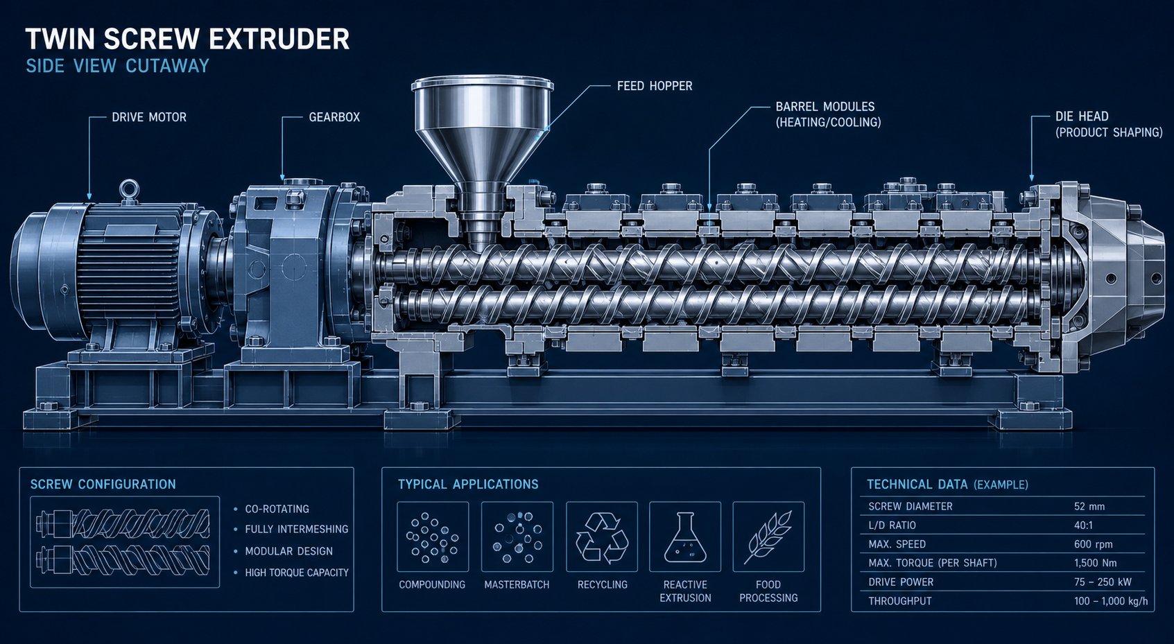
A schematic diagram of a twin screw extruder is a labeled technical drawing that maps every major mechanical component, material flow path, and functional zone of the machine from the drive motor to the die head. It serves as the universal language between design engineers, maintenance crews, process technicians, and procurement teams evaluating equipment.
If you have ever asked "what is a twin screw extruder" and landed on a page filled with generalities, this article takes a different path. Instead of repeating the basics, it is built as a schematic reading guide - a virtual walk-through that mirrors the way a real engineering drawing is laid out, moving component by component from the drive end all the way downstream to the die.
Here is something that trips people up right away: the phrase "schematic diagram" does not point to a single drawing type. Depending on your role and what you need to accomplish, you could be looking at a mechanical cross-section, a screw profile configuration chart, a process flow diagram, or a piping and instrumentation diagram (P&ID). Each one speaks to a different audience at a different level of detail, and confusing them leads to costly miscommunication with OEMs and vendors.
What a Twin Screw Extruder Schematic Actually Shows
Imagine unfolding a twin-screw extruder lengthwise and labeling every part you see. That is essentially what a mechanical cross-section schematic does. It depicts the motor, gearbox, thrust bearings, modular barrel segments, screw elements, venting ports, and die assembly - all positioned in their real spatial relationship with dimensional callouts and directional arrows showing material flow. Design engineers rely on these drawings during development, maintenance crews reference them for part identification and troubleshooting, and purchasing teams use them to specify exact replacement components when placing orders.
Why Understanding the Diagram Matters for Operations
Reading schematics is not just an engineering exercise. For operators and technicians on the floor, schematic literacy translates directly into faster troubleshooting, more accurate parts ordering, and clearer communication during equipment audits or upgrades. When a process technician can point to a specific barrel segment or screw element on a drawing, conversations with service teams move from vague descriptions to precise action items.
Teams that can fluently read twin screw extruder schematics consistently report shorter unplanned downtime and fewer miscommunication errors when sourcing parts or coordinating with OEM support.
Twin screw extruders are complex machines with modular architectures, and their schematics reflect that complexity. The sections ahead break down each drawing type you are likely to encounter, then walk through every component zone - drive assembly, barrel segments, screw elements, functional processing zones, and die head - exactly as they appear on a standard engineering layout.
Four Types of Twin Screw Extruder Schematics Engineers Use
That phrase "schematic diagram" gets tossed around in technical conversations as if it refers to one specific document. In practice, engineers working with a twin screw extruder machine rely on at least four distinct drawing types, each built for a different purpose and read by a different audience. Grabbing the wrong one when you need to troubleshoot a barrel alignment issue or specify a control loop wastes time and invites errors. The breakdown below will help you pinpoint exactly which schematic fits the task at hand.
Mechanical Cross-Section Schematic
This is the drawing most people picture when they hear "extruder schematic." It is a side-view cutaway that slices the twin-screw extruder machine open lengthwise, exposing every internal component in its true spatial position. You will see the barrel bore rendered as a figure-eight profile for intermeshing screws, heating jackets drawn as coil or zigzag symbols wrapped around each barrel segment, and dimensional callouts marking critical tolerances.
Labeling conventions on these drawings follow a fairly consistent pattern. The drive motor appears as a rectangular block with annotations for power rating in kilowatts and RPM range. Bearings are represented by small opposing triangles or "X" symbols inside circles. Shaft seals show up as paired lines at the interface between rotating and stationary parts. Material flow direction is indicated by arrows running from the feed port toward the die, giving readers an immediate sense of upstream versus downstream orientation.
Maintenance crews and equipment evaluators lean on this schematic heavily because it shows part-to-part relationships at a glance - where a seal sits relative to a bearing housing, how barrel segments bolt together, and how much clearance exists between screw flights and the bore wall.
Screw Profile and Configuration Diagram
If the cross-section is a photograph, the screw profile diagram is more like a recipe laid out on a timeline. It presents the full sequence of screw elements arranged linearly along the shaft, typically in a top-down or "unrolled" view. Each element is annotated with a code that tells you its type, pitch, length, and rotation direction.
For example, a conveying element labeled SE 30/30 R indicates a screw element with a 30 mm pitch, 30 mm segment length, and right-hand (forward) rotation. Kneading blocks carry codes like KBW 45/5/30 R, where 45 is the angular offset between discs, 5 is the number of discs, 30 is the segment length in millimeters, and R denotes the conveying direction. NC State Extension's screw profile research provides detailed nomenclature tables that map these element codes to their functional roles - conveying, kneading, re-conveying, and distributive mixing.
Process engineers designing or modifying twin-screw extruders spend considerable time on this diagram because the order, length, and type of each element directly control shear input, residence time, and mixing intensity. Swapping a forward kneading block for a neutral one in the wrong position can shift the entire process window.
Process Flow Diagram and P&ID Differences
Step back from the machine itself and you enter the territory of system-level drawings. A Process Flow Diagram (PFD) shows how raw material moves through the entire extrusion line at a high level - from the hopper, through the extruder twin screw assembly, past the die, and into downstream equipment like pelletizers or cooling baths. Major equipment appears as simplified blocks or standard symbols, and the diagram includes operating conditions such as temperature, pressure, and flow rate at key points. PFDs are typically developed following ISO 10628 standards and are used during conceptual design, feasibility studies, and process simulation.
A Piping and Instrumentation Diagram (P&ID) builds on that same process flow but adds a layer of operational detail that construction and maintenance teams cannot do without. You will find every valve tagged and specified, control loops drawn with ISA-standard instrument symbols, pressure relief devices marked at their exact locations, and utility connections for cooling water and heating media fully documented. Where a PFD might show "Barrel Zone 3 - 220 degrees C" as a simple annotation, the corresponding P&ID will depict the thermocouple type, its wiring path to the PLC, the control valve on the heating circuit, and the alarm setpoint.
The practical takeaway? A PFD tells you what the process does. A P&ID tells you how it is built and controlled. Most extrusion facilities need both, and confusing one for the other during a vendor discussion or HAZOP review creates blind spots that are expensive to fix later.
The table below puts all four schematic types side by side so you can quickly match each drawing to the right task and team.
| Schematic Type | Purpose | Typical Audience | Level of Detail |
|---|---|---|---|
| Mechanical Cross-Section | Show internal components, spatial relationships, and dimensional tolerances of the extruder | Design engineers, maintenance crews, equipment buyers | High - individual parts, clearances, materials of construction |
| Screw Profile / Configuration Diagram | Map the linear sequence of screw elements along the shaft with element codes and lengths | Process engineers, R&D teams, screw element suppliers | Medium-High - element-by-element layout with pitch, offset, and rotation data |
| Process Flow Diagram (PFD) | Illustrate overall material and energy flow through the complete extrusion line | Project managers, process engineers, stakeholders evaluating feasibility | Low-Medium - major equipment blocks, stream conditions, no piping or instrumentation detail |
| Piping and Instrumentation Diagram (P&ID) | Document all piping, valves, instruments, control loops, and safety systems for construction and operation | Control engineers, construction teams, operations and maintenance staff | Very High - every valve, sensor, control loop, and safety device tagged and specified |
Each of these four drawings captures a different slice of the same machine. Knowing which one to pull off the shelf - or which one to request from an OEM - depends entirely on the question you are trying to answer. A barrel alignment check calls for the mechanical cross-section. A screw redesign starts with the profile diagram. A plant-wide capacity study needs the PFD, while commissioning a new temperature control loop demands the P&ID.
With the drawing types sorted out, the real payoff comes from understanding what each section of the most referenced schematic - the mechanical cross-section - actually depicts. That story begins at the drive end of the machine, where motor torque first enters the system.
Drive-End Components from Motor to Barrel Entrance
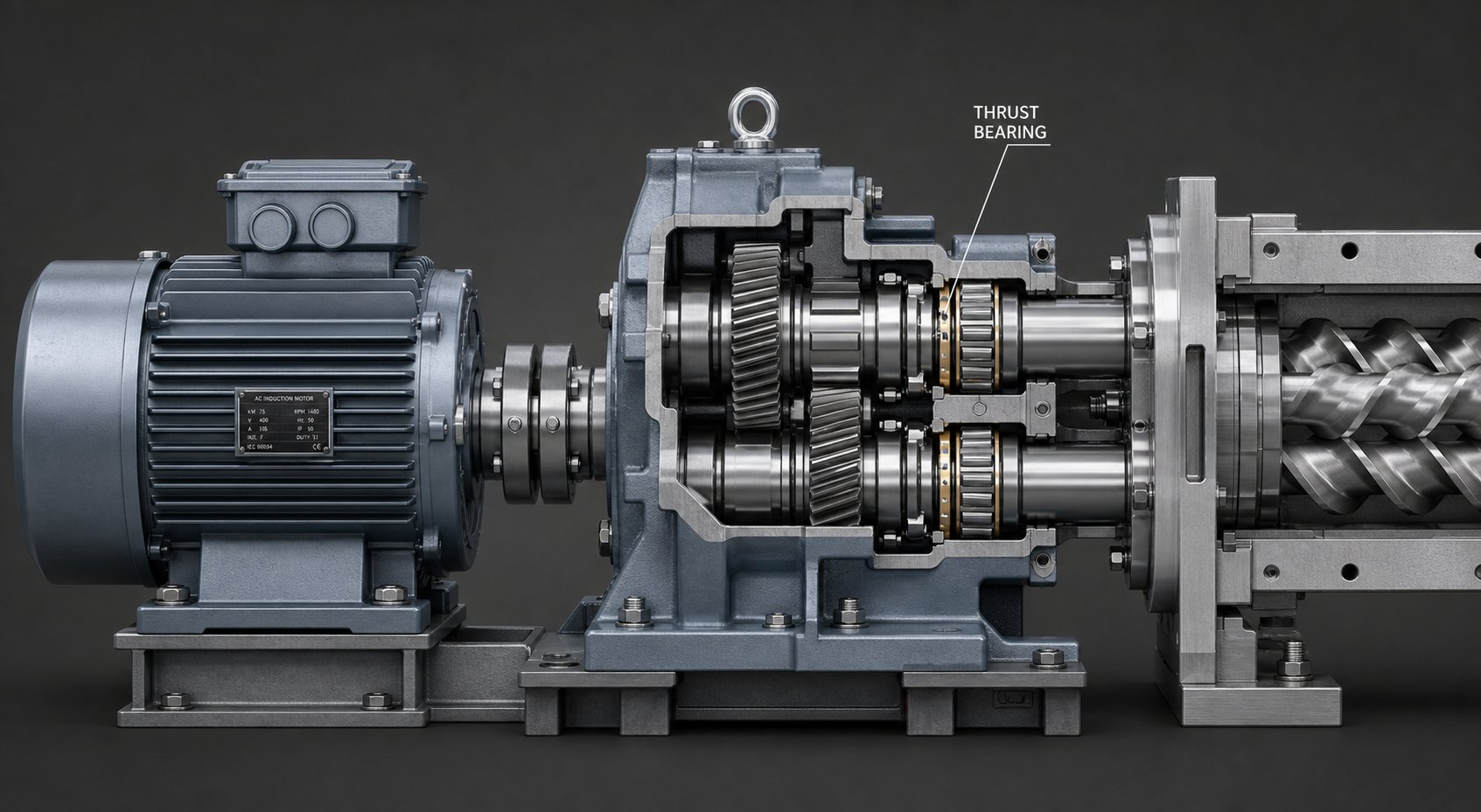
Every mechanical cross-section schematic of a twin screw extruder reads like a sentence - and the first word is always the drive motor on the far upstream end. Whether the drawing convention places it on the far left or the far right, the drive side is your starting point for understanding how raw electrical energy transforms into the precise rotational force that pushes polymer through the barrel. Walk through this section of the schematic and you will encounter three major assemblies before a single pellet of resin ever enters the machine.
Drive Motor and Coupling Assembly
On most schematics, the electric drive motor appears as a large rectangular or cylindrical block at the extreme drive-side edge of the drawing. Annotations clustered around this symbol typically include the power rating in kilowatts (kW), the nominal RPM range, and the motor type - almost always an AC induction motor paired with a variable frequency drive (VFD) on modern lines. You might also see a notation for the number of poles, which determines the base speed. A standard four-pole motor, for instance, has a base speed of roughly 1,500 RPM at 50 Hz or 1,800 RPM at 60 Hz.
Connecting the motor output shaft to the gearbox input shaft is the coupling, depicted on schematics as a short hatched or cross-sectioned segment between the two blocks. The coupling type matters more than it might seem at first glance. Most parallel twin screw extruder installations use a flexible coupling - either an elastomeric jaw coupling or a gear-tooth coupling - designed to absorb minor angular and parallel misalignment between the motor and gearbox shafts. Schematic annotations here typically call out the coupling model, maximum torque rating, and any torsional damping characteristics. A rigid coupling drawn in this position would signal a system that demands extremely precise shaft alignment, since it has zero tolerance for offset.
Why should you care about the coupling symbol on the drawing? Because it tells you how forgiving the drive train is during thermal expansion. When the machine heats up to operating temperature, the gearbox housing and motor frame expand slightly, shifting shaft positions by hundredths of a millimeter. A flexible coupling absorbs that movement silently. A mismatched or worn coupling transmits it straight into the gearbox bearings as vibration - one of the earliest and most overlooked sources of drive-side trouble.
Gearbox and Speed Reducer
Move one step downstream on the schematic and you hit the most detailed, most heavily annotated block in the entire drive section: the gearbox. This component converts the motor's high-speed, low-torque output into the low-speed, high-torque rotation the screws need. On a typical drawing, the gearbox appears as a large rectangular housing with internal gear trains shown in cutaway, and you will notice more dimensional callouts here than on almost any other component.
The key annotations to look for include the overall gear ratio (for example, 6:1 or 12:1), which tells you how much the motor speed is reduced and, inversely, how much the torque is multiplied. A 12:1 ratio means the screws turn at one-twelfth of the motor speed while receiving twelve times the motor's torque output. Schematics also indicate the output shaft orientation - whether the two shafts exit horizontally in parallel, matching the screw centerline spacing exactly.
Inside the housing, you will often see two or three reduction stages drawn as meshing gear pairs. The distribution stage is where the schematic gets particularly interesting. This is the mechanism that takes a single input stream of rotational energy and splits it equally between two output shafts. In a parallel three-axis gear structure, power flows to both output shafts simultaneously, but the constrained shaft (commonly called the B-axis) has smaller gears due to the tight center distance between screws. Improved designs use a double-sided symmetrical drive structure that feeds the B-axis from two directions, canceling radial loads and doubling effective torque capacity.
Lubrication system connections are also annotated on the gearbox portion of the schematic. You will see oil fill ports, drain plugs, sight glass indicators, and - on larger production units - connections to external oil circulation and cooling systems. These details are critical for maintenance planning because the twin screw extruder gearbox is typically the single most expensive component in the entire machine. Engineering references consistently describe it as the component whose torque capacity defines the upper processing limit of the whole extrusion line. Treat it accordingly when reading or interpreting any schematic.
Thrust Bearing Assembly and Torque Distribution
Between the gearbox output and the first barrel section, the schematic shows a component that is easy to overlook but impossible to do without: the thrust bearing assembly. Its job is to absorb the axial forces generated when the screws push material forward against die resistance. That reaction force - Newton's third law at work - shoves the entire screw assembly backward toward the drive end. Without a robust thrust bearing package to catch that load, the screws would hammer directly into the gearbox internals.
On schematics, the thrust bearing assembly is typically depicted as a set of stacked angular contact ball bearings or tapered roller bearings, drawn between the gearbox output shaft and the point where the screw shaft enters the first barrel segment. Annotations in this zone include the rated axial load capacity in kilonewtons (kN) and, on well-detailed drawings, a torque-limiting notation that defines the maximum allowable back pressure before the bearing system reaches its fatigue threshold. In twin screw extruders, back-pressure forces range from 2.5 kN on small laboratory machines to 3,400 kN on large production units, so the thrust bearing sizing directly governs how hard you can push the process.
Imagine pressing your palm flat against a wall and pushing as hard as you can. Your shoulder joint absorbs that reaction force the same way the thrust bearing absorbs screw back-pressure. Overload it, and the joint (or bearing) fails through fatigue long before the pushing mechanism itself gives out. That is why many twin screw extruder machine manufacturers annotate the thrust bearing section with a specific safety margin and recommended inspection intervals.
Putting it all together, here is the exact sequence of drive-end components as they appear on a standard schematic, reading from the power source toward the first barrel segment:
- Electric drive motor - provides rotational energy, annotated with kW rating, RPM range, and pole count.
- Flexible coupling - connects motor output shaft to gearbox input, absorbs minor misalignment and thermal expansion.
- Gearbox (speed reducer and torque distributor) - reduces speed, multiplies torque, and splits power equally to two synchronized output shafts at the exact screw center distance.
- Thrust bearing assembly - absorbs axial reaction forces from screw back-pressure, annotated with rated axial load in kN and a torque-limiting threshold.
- Screw shaft coupling (output side) - connects gearbox output shafts to the twin screw shafts entering the barrel, maintaining precise angular alignment and torque transfer.
Each of these components occupies a distinct zone on the schematic, and together they form the mechanical foundation that everything downstream depends on. A motor that is oversized relative to the gearbox input rating, a coupling that cannot handle thermal growth, or a thrust bearing rated below the actual process back-pressure - any one of these mismatches will cascade into premature wear, vibration, and unplanned downtime.
The drive assembly delivers torque and absorbs reaction forces, but it channels all of that energy into a very specific destination: the modular barrel, where raw material first meets the rotating screws. How that barrel is segmented, ported, and temperature-zoned on the schematic reveals the processing architecture of the entire machine.
Barrel Segment Layout and Temperature Zone Mapping
Torque has traveled from the motor through the gearbox and thrust bearings, and the screw shafts are spinning at their target RPM. Where does all that rotational energy go? Into the barrel - the long, modular housing that contains both screws and defines every processing condition the material will experience. On a schematic diagram of a twin screw extruder, the barrel section dominates the drawing's real estate, and for good reason: its configuration dictates feeding locations, venting positions, temperature profiles, and ultimately, product quality.
Closed and Open Barrel Segments on the Schematic
Unlike a single screw extruder's one-piece barrel, a twin screw extruder barrel is assembled from individual modular segments bolted together in series. Each segment is typically 4:1 or 5:1 L/D in length, and schematics number them sequentially - Barrel 1, Barrel 2, Barrel 3 - starting from the feed end and moving downstream toward the die. This numbering convention gives every team member, from the process engineer to the parts buyer, an unambiguous reference point when discussing a specific location on the machine.
You will notice two distinct barrel representations on any extruder twin screw barrel schematic. Closed barrel segments appear as solid rectangular outlines with no openings along the top or sides. These are positioned at high-pressure compounding and pumping zones where the material must remain fully contained. Open barrel segments, by contrast, feature port annotations - circles or rectangles cut into the top or side of the outline - indicating locations for feeding, venting, or liquid injection. The distinction is critical: placing a closed segment where a vent port is needed traps volatiles in the melt, while leaving an open port at a high-pressure zone causes material leakage or vent flooding.
A well-documented schematic also shows the bore profile within each segment. For intermeshing twin screw extruders, this bore appears as a figure-eight cross-section, and wear-resistant liners or bimetallic inserts may be annotated with material callouts such as 38CrMoAlA or HIP alloy, depending on the abrasion and corrosion demands of the application.
Side-Feeding, Venting, and Liquid Injection Barrels
Specialized barrel segments are where the schematic really starts to tell the story of your process. Each port type has a distinct symbol and annotation convention that experienced readers can identify at a glance. Sidefeeders for twin screw extruders, for example, appear as perpendicular inlet tubes with a small twin screw auger symbol inside - reflecting the corotating side stuffer that physically pushes fillers, reinforcements, or secondary polymers into the melt stream. A side stuffer is essentially a miniature twin screw device that forces material into the main process, bypassing the high-shear melting zone upstream.
Here is a quick reference list of the barrel segment types you will encounter on a typical twin screw plastic extruder schematic, along with their standard symbols and annotations:
- Closed barrel segment - Solid rectangular outline, no ports. Used at high-pressure mixing, kneading, and pumping locations.
- Feed barrel (main feed port) - Open top port with a funnel or hopper symbol above. Positioned at Barrel 1 or Barrel 2, where raw material enters by gravity or through a loss-in-weight feeder.
- Side-feeder barrel - Perpendicular inlet on the side or top with a twin auger symbol. Allows downstream addition of fillers, glass fiber, or heat-sensitive additives directly into the melt.
- Atmospheric vent barrel - Upward-facing rectangular opening, sometimes with a vent stack symbol. Permits moisture and trapped air to escape at zero gauge pressure.
- Vacuum vent barrel - Upward-facing opening connected to a vacuum pump symbol via a trap or condenser. Removes residual solvents, moisture, and volatile contaminants under negative pressure.
- Liquid injection barrel - Small circular port with a nozzle or spray symbol, often connected to a gear pump or piston pump icon. Used for introducing plasticizers, liquid additives, or reactive agents into the melt at controlled flow rates.
The placement sequence of these segments on the schematic is never random. It mirrors a carefully engineered process design where solids enter first, fillers join the melt downstream after initial compounding, and vents are positioned just after mixing zones where volatile generation peaks. Misreading this sequence - or reordering segments during a rebuild - can collapse the entire process window.
Temperature Zone Mapping on Barrel Schematics
Each barrel segment corresponds to an independent temperature control zone, and schematics depict this relationship with symbols that are easy to spot once you know what to look for. Electric band heaters or cartridge heaters appear as zigzag or coil symbols wrapped around or embedded within the barrel section outline. Modern modular barrels use internal cartridge heaters paired with internal cooling bores - shown as parallel lines running through the barrel wall with water flow arrows indicating inlet and outlet directions.
Temperature setpoints are annotated directly on or adjacent to each zone, often in a row of values beneath the barrel layout: Zone 1 at 120 degrees C, Zone 2 at 180 degrees C, Zone 3 at 220 degrees C, and so on. This gradient is not decorative - it reflects the deliberate thermal profile that controls melting onset, mixing viscosity, and melt stability as the material advances downstream. On a twin screw extruder plastic processing line, precise thermal control in these zones determines whether the final product meets specification or degrades during transit through the barrel.
Thermocouple placement is annotated as small probe symbols inserted into the barrel wall, usually positioned at the midpoint of each segment and penetrating to within a few millimeters of the bore surface. Some schematics distinguish between barrel wall thermocouples (measuring metal temperature) and melt thermocouples (protruding into the flow channel to measure actual material temperature). The difference matters for process control: barrel wall readings respond faster to heater changes, while melt readings reflect what the material is actually experiencing.
Cooling channels deserve special attention on the schematic because they reveal how aggressively a zone can remove heat. Internal cooling bores positioned close to the barrel liner provide the most efficient heat transfer and support higher screw speeds without overheating - an evolution that became standard in the 1980s as RPM capabilities increased. When you see dual inlet and outlet annotations on a cooling circuit, that signals a high-flow-rate design capable of handling the intense shear energy generated by aggressive kneading block configurations in that zone.
Together, the heater symbols, cooling channel paths, and thermocouple positions on the schematic form a thermal map of the entire barrel. Reading this map tells you not just what temperatures the process targets, but how quickly each zone can heat up, cool down, and respond to disturbances - information that is essential for troubleshooting temperature overshoot, optimizing cycle times, and specifying replacement heating elements during maintenance.
The barrel provides the thermal environment and physical containment, but the real processing work happens on the components spinning inside it. The screw elements - their geometry, sequence, and interaction with each barrel zone - are what transform raw feedstock into a homogeneous melt, and their representation on profile diagrams carries its own set of codes and conventions.
Screw Element Geometry and Configuration Diagrams Decoded
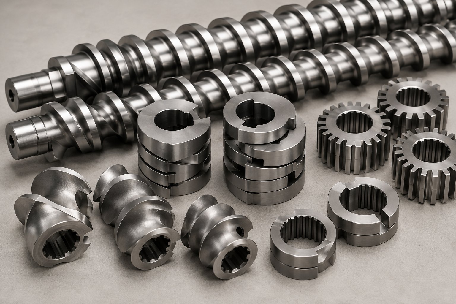
The barrel houses the process, but the screw elements define it. Every gram of material that enters a twin screw extruder is conveyed, sheared, kneaded, mixed, and metered by the rotating elements assembled on the twin shafts. When you look at a screw profile diagram on any schematic, you are looking at the recipe that determines product quality, throughput limits, and energy consumption. Understanding the geometry codes and element sequences drawn on these diagrams is what separates operators who react to problems from engineers who prevent them.
Screw Geometry Terminology on Cross-Section Views
Pick up a cross-section schematic of any twin screw extruder elements and you will find a handful of geometric parameters called out repeatedly with dimensioning lines. These are the fundamental measurements that define how each element interacts with the material flowing through it. Twin-screw extruders use self-wiping screw element geometry identified as Erdmenger profiles, and every element on the shaft is characterized by the same core set of dimensions.
The table below defines each parameter, explains how it appears on engineering schematics, and describes what it actually controls during processing.
| Geometric Parameter | Schematic Representation | Functional Significance |
|---|---|---|
| Pitch | Horizontal dimension line spanning the axial distance between two consecutive flights | Controls conveying rate and shear input. Increasing pitch increases material transport speed but reduces pressure buildup. |
| Lead | Often annotated alongside pitch; equals pitch multiplied by the number of flights (starts) | Defines the axial distance material advances per full screw revolution. A double-flighted element has a lead twice its pitch. |
| Flight Thickness | Short callout line across the land (top) of the flight in cross-section view | Affects self-wiping action and wear resistance. Thicker flights improve barrel cleaning but reduce free channel volume. |
| Channel Depth | Vertical dimension from the flight tip down to the screw root in cross-section | Determines free volume available for material. Deeper channels increase throughput capacity; shallower channels raise shear intensity. |
| Channel Width | Horizontal dimension between adjacent flights measured at the screw root | Works with channel depth to set the cross-sectional flow area. Narrower channels compress material and boost dispersive action. |
Sounds like a lot of numbers? Here is the practical shortcut: channel depth decreases in the order of conveying, compression, and metering zones. When you scan a screw profile diagram from the feed end to the die end, you should see the annotated channel depth values getting progressively smaller, reflecting increasing pressure and shear as material moves downstream. If they do not follow that trend, you are likely looking at a specialized configuration - perhaps a filler masterbatch twin screw extruder profile designed with deep-channel elements further downstream to accommodate high filler loadings without excessive torque spikes.
Conveying Elements and Kneading Blocks in Profile Diagrams
A screw profile diagram lays out the full sequence of screw elements twin screw extruder shafts carry, drawn linearly from the feed end on one side to the die end on the other. Each element is represented as a coded block or symbol, and reading these codes fluently is essential for anyone specifying, troubleshooting, or redesigning a screw configuration.
Forward-conveying elements are the workhorses. On profile diagrams, they appear as helical or hatched blocks with right-hand arrows indicating forward material transport. Their element codes follow a standardized format - for instance, SE 30/30 R designates a screw element with a 30 mm pitch, a 30 mm segment length, and right-hand (forward) rotation. A larger pitch element like SK 40/40 R moves a greater bulk of material per revolution but generates less pressure buildup, making it ideal for the feed zone where you need volume, not compression.
Reverse-conveying elements are drawn with left-hand arrows, and their codes end in L instead of R. Elements such as SE 10/10 L or SE 20/20 L deliberately slow down material flow, pushing it backward to create localized restriction. Process engineers place them just before or after kneading blocks to increase residence time and intensify shear. A key rule of thumb drawn from extrusion research at NC State: the length of reverse elements should stay shorter than the screw diameter to prevent dangerous pressure peaks and excessive shear strain in the material.
Kneading blocks are depicted as stacked disc segments with angular offset annotations between each disc. The offset angle is the signature detail that tells you exactly how aggressive the mixing action will be:
- 30 degrees offset - Narrow, primarily distributive mixing. Spreads the dispersed phase evenly without breaking down particles aggressively. Forward conveying effect.
- 60 degrees offset - Medium, balanced between distributive and dispersive action. Moderate forward conveying.
- 90 degrees offset - Wide or neutral. No forward conveying effect, which means material dwells in this zone longer and absorbs maximum shear energy. Used where intensive dispersive mixing is required.
Kneading block codes add further detail. A KP 45/5/20 R element, for example, is a kneading block with half-disc widths, 45-degree disc offset, 5 discs, 20 mm total length, and right-hand rotation - producing moderate distributive mixing with a slight forward push. Switch to KBW 45/5/30 L and you get full-disc-width kneading blocks with left-hand (reverse) rotation - a much more aggressive dispersive mixing action that also restricts material flow.
Toothed mixing elements (TME) and gear mixing elements (ZME) fill a different role on the profile diagram. Coded as something like Z 8/3/20 - indicating 8 teeth, 3 tooth rows, and 20 mm length - these elements combine gentle forward conveying with strong distributive mixing. On schematics, they appear as serrated or gear-like blocks positioned in zones where solid and liquid ingredients need thorough blending without the high shear that kneading blocks impose. They are especially valuable in a compounding twin screw extruder processing heat-sensitive additives or color concentrates that degrade under excessive mechanical energy.
How Screw Configuration Determines Processing Performance
Reading individual element codes is useful, but the real insight comes from seeing how the entire sequence works together on a profile diagram. The arrangement of conveying, kneading, and mixing elements creates distinct processing zones - and every zone exists because the elements in that section were chosen to perform a specific mechanical and thermal function on the material passing through.
Consider a typical twin screw compounding extruder profile for a filled polypropylene compound. The feed zone starts with large-pitch forward-conveying elements (SK 40/40 R) to pull material in quickly without starving the system. A few barrel segments downstream, a block of progressively tighter kneading elements (KBW 45/5/30 R followed by KP 90/5/20) creates the high-shear melting and dispersive mixing zone. After a brief reverse element (SE 10/10 L) that seals the melt, a vented section uses moderate conveying elements to allow volatiles to escape. Further downstream, toothed mixing elements homogenize the melt before a final metering section of consistent-pitch conveyors builds the pressure needed to push material through the die.
Change one element in that sequence - swap a 90-degree neutral kneading block for a 30-degree forward one, for instance - and you shift the entire shear profile. Residence time drops, dispersive mixing weakens, and filler agglomerates that should have been broken apart survive all the way to the pelletizer. That is why screw barrel components are precision-engineered and must match barrel specifications exactly. Element outer diameters are machined to maintain tight clearances with the barrel bore, and element inner diameters are broached to fit the shaft spline profile with zero play.
For teams that need to replace worn elements or upgrade a screw configuration identified on their schematic, sourcing precision-matched components is essential. NANHAIYA's screw barrel support provides extrusion manufacturers and technical teams with screw barrel components matched to specific extruder configurations and processing requirements - a practical starting point when translating a profile diagram into an actual parts order.
A screw profile diagram is not just a parts list. It is a processing blueprint where every element code, offset angle, and sequence position directly controls product quality, energy consumption, and throughput capacity.
Individual elements and their codes reveal the micro-level design intent, but stepping back to view the full schematic from feed hopper to die head reveals the macro-level architecture - a series of distinct functional zones, each performing a specific transformation on the material as it travels downstream.
Five Functional Zones from Feed Hopper to Die Head
Screw element codes and barrel segment numbers tell you what individual parts do, but zoom out to the full schematic and a bigger picture emerges. The entire machine organizes itself into a series of functional zones, each performing a distinct transformation on the material as it progresses from raw pellets or powder to a shaped product exiting the die. Understanding how does a twin screw extruder work at the system level means recognizing these zones, knowing where each one starts and ends on the drawing, and seeing how the screw profile, barrel ports, and temperature setpoints all coordinate within each region.
Most schematics do not label these zones explicitly. Instead, you infer them from the combination of element types, barrel configurations, and thermal annotations in each region. The breakdown below maps each zone to its visual footprint on a standard mechanical cross-section and screw profile diagram.
Feed Zone and Melting-Compression Zone on the Schematic
The feed zone occupies the first one to three barrel segments at the upstream end of the drawing. Its most recognizable feature is the feed hopper - rendered as a funnel or inverted trapezoid symbol sitting above an open barrel port. Gravity or a loss-in-weight feeder drops raw material into this opening, and the screws below pull it forward.
Look at the screw profile diagram in this region and you will see large-pitch forward-conveying elements dominating. Elements coded something like SE 40/40 R or SK 60/60 R are typical - high free volume, deep channels, and aggressive forward transport. The goal is simple: grab as much material as possible and move it downstream without compacting it prematurely. Temperature setpoints annotated beneath the first barrel segments are relatively low, often between 80 and 150 degrees C, because the material is still solid and excessive heat here can cause premature melting that blocks the feed throat.
Transition into the melting-compression zone happens gradually, and schematics reflect this through two simultaneous changes. First, the screw profile shifts from pure conveying elements to a mix of conveying elements and kneading blocks. You will start seeing codes like KBW 45/5/30 R appearing in sequence, their stacked-disc symbols replacing the smooth helical blocks of the conveying section. Second, barrel temperature annotations climb sharply - Zone 3 might read 200 degrees C, Zone 4 jumps to 240 degrees C. This combination of increasing shear from kneading blocks and rising barrel heat transforms solid pellets into a cohesive melt through what twin screw extrusion zone research describes as the combined action of external barrel heating and internal shear heat generated by the screw elements.
On the cross-section schematic, you may also notice the channel depth annotations decreasing through this transition. Shallower channels compress the softening material, improving contact with heated barrel walls and accelerating the phase change from solid to melt. The compression zone essentially squeezes the air out of the loosely packed feed and forces intimate polymer-to-metal contact.
Mixing-Kneading Zone and Metering Zone
Move further downstream on the schematic and you reach the section where the real processing intensity peaks. The mixing-kneading zone is visually dense on a screw profile diagram - packed with kneading blocks at 60- and 90-degree offsets, gear mixing elements, and possibly reverse-conveying restrictors that create melt seals. This is where distributive and dispersive mixing happen simultaneously, breaking apart filler agglomerates, blending polymer phases, and ensuring every additive is uniformly distributed throughout the melt matrix.
The barrel segments corresponding to this zone carry the highest temperature setpoints on the schematic, often reaching 240 to 280 degrees C for standard polyolefin compounds and up to 450 degrees C for high-performance engineering polymers. One of the key advantages of twin screw extruder design is the ability to create multiple mixing-kneading zones along the barrel length, each separated by conveying sections that allow the melt to relax before the next round of intensive shear. This modularity is clearly visible on the profile diagram as alternating clusters of kneading blocks and conveying elements.
Venting sections frequently appear within or immediately after mixing zones. On the schematic, you will spot atmospheric or vacuum vent ports - the upward-facing openings discussed in the barrel segment section - positioned right after a reverse element or melt seal. The logic is straightforward: mixing generates volatiles (moisture, trapped air, reaction byproducts), and the vent gives them an escape route before the material moves into the final zone. Large-pitch conveying elements beneath vent ports expand the melt's free surface area to improve devolatilization efficiency.
The metering zone sits at the downstream terminus of the screw profile, just before the die. Visually, it is the calmest section on the diagram - a consistent run of moderate-pitch forward-conveying elements such as SE 20/20 R or SE 30/30 R with no kneading blocks or mixing elements interrupting the flow. Its purpose is to build stable, uniform melt pressure and deliver a consistent volumetric flow rate to the die head. The barrel temperature here is typically set close to the final processing temperature, adjusted to balance melt viscosity against thermal degradation risk. Channel depth in this region is shallow, improving filling efficiency and pressure-building capability as the melt approaches the exit.
Die Head and Shaping Zone
At the far downstream end of any twin screw extruder schematic, the barrel gives way to the die head assembly. This is where geometry changes from the figure-eight bore of the barrel to the specific shape of the final product, and the schematic reflects that transition with a distinct set of annotations.
Between the last barrel segment and the die, most schematics show a screen changer and breaker plate. The breaker plate appears as a perforated disc symbol spanning the full bore cross-section. It serves a dual purpose: supporting the screen pack that filters contamination from the melt, and breaking up the rotational memory (spiraling flow pattern) that the screws impart to the material. The screen pack sits upstream of the breaker plate - one or more layers of woven metal mesh that catch gels, carbonized particles, and foreign contaminants before they reach the die flow channels. On detailed schematics, the screen changer mechanism is drawn as a slide plate or piston block, with annotations indicating whether it is manual, hydraulic, or continuous.
The die itself is annotated for geometry specific to its application of twin screw extruder output. An annular die for pipe extrusion shows concentric circles with mandrel and die land dimensions. A flat die for sheet or film production appears as a wide, narrow-slot cross-section with lip gap annotations. A strand die for pelletizing is drawn as a plate with multiple small circular orifices, each hole sized to produce a consistent strand diameter. These die-end annotations connect the schematic directly to the product - they tell you what the machine is actually making.
Here is the complete sequence of functional zones as they appear on a standard twin screw extruder schematic, reading from upstream to downstream:
- Feed zone - Identified by the hopper symbol above an open barrel port and large-pitch conveying elements on the screw profile; low temperature setpoints; primary role is material intake and initial forward transport.
- Melting-compression zone - Marked by the transition from conveying elements to kneading blocks, rising barrel temperature annotations, and decreasing channel depth callouts; converts solid feedstock into a cohesive melt through combined shear and thermal energy.
- Mixing-kneading zone - Recognized by dense clusters of kneading blocks and mixing elements on the profile diagram, the highest barrel temperature setpoints, and adjacent vent port symbols; delivers dispersive and distributive mixing to homogenize the melt and blend all components.
- Metering zone - Shown as a uniform run of consistent-pitch forward-conveying elements with shallow channel depth; builds stable pressure and delivers a steady volumetric flow to the die.
- Die head and shaping zone - Depicted at the downstream terminus with breaker plate, screen changer, and die geometry annotations specific to the final product form (pipe, sheet, strand, or profile).
These five zones do not have hard physical boundaries on the real machine - material transitions gradually from one state to the next. But on the schematic, you can trace each zone by following the progression of screw element codes, barrel port symbols, and temperature setpoints from left to right across the drawing. That systematic reading skill is what transforms a dense engineering diagram into an actionable process map.
Each zone described above assumes the screws rotate in the same direction, which is the most common configuration for compounding and reactive extrusion. But twin screw extruders come in two fundamentally different rotation arrangements, and their schematics look notably different when you examine the cross-sectional views and barrel bore profiles side by side.
Co-Rotating vs Counter-Rotating Schematic Differences
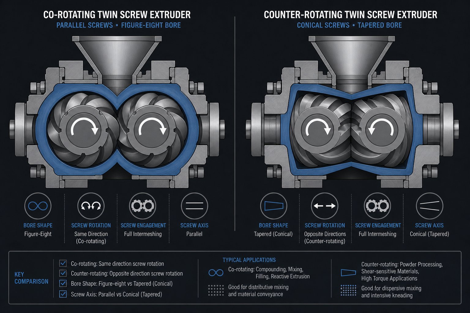
Two twin screw extruder schematics can depict machines that look almost identical in side view yet behave in fundamentally different ways. The difference between co rotating and counter rotating twin screw extruder designs becomes obvious the moment you examine the cross-sectional view — the small circular diagram usually drawn near the feed end of the schematic showing both screws head-on. That single view tells you the rotation direction, intermeshing type, bore geometry, and by extension, the entire processing philosophy of the machine.
Co-Rotating Twin Screw Extruder Schematic Features
Open the cross-section view of a co-rotating twin screw extruder and you will see two curved arrows pointing in the same direction — both clockwise or both counterclockwise. The screws are fully intermeshing, meaning the flight of one screw reaches deep into the channel of the other. This tight geometric relationship creates a self-wiping profile where each screw continuously scrapes material off its partner, preventing stagnant zones and dead spots inside the barrel.
The barrel bore on these schematics appears as a figure-eight shape — two overlapping circles that accommodate the intermeshing geometry. A co-rotating parallel twin screw extruder uses a constant bore diameter from the feed end to the die end, and the L/D ratio annotated on the schematic typically falls between 32:1 and 56:1, reflecting the longer processing length needed for complex compounding tasks.
Screw profile diagrams for co-rotating twin-screw extruder configurations tend to be the most complex you will encounter. Expect to see numerous element transitions — clusters of kneading blocks at varying offsets, toothed mixing elements, reverse conveyors, and multiple venting sections. This modular versatility is precisely why the co-rotating layout dominates schematics for compounding, reactive extrusion, devolatilization, and masterbatch production.
Counter-Rotating Twin Screw Extruder Schematic Features
Flip to a counter rotating twin screw extruder schematic and the cross-section tells a different story. The rotation arrows point in opposite directions — one clockwise, the other counterclockwise. The screws may be closely intermeshing or only partially intermeshing, depending on the design intent.
Here is where barrel bore geometry diverges sharply. A parallel counter-rotating design retains the figure-eight bore, but the most widely used variant — the conical twin screw extruder — features a tapered barrel bore that is wide at the feed end and narrows progressively toward the die. On the schematic, this taper is unmistakable: the barrel outline converges from left to right, and the screw diameters decrease accordingly. That conical geometry builds compression naturally without relying heavily on screw element changes, which simplifies the overall screw profile compared to its co-rotating counterpart.
PVC pipe, profile, and sheet extrusion schematics typically depict this configuration. The counter-rotating action creates a calendering effect between the screws — material is squeezed in the gap where the flights meet, generating excellent pressure buildup with relatively low shear. For heat-sensitive materials like rigid PVC, that combination is essential because excessive shear energy causes thermal degradation and discoloration.
Key Structural Differences Visible on Schematics
When you place a co rotating and counter rotating twin screw extruder schematic side by side, six structural features stand out immediately. The table below maps each one so you can identify any configuration at a glance.
| Feature | Co-Rotating | Counter-Rotating |
|---|---|---|
| Screw Rotation Direction | Both screws rotate in the same direction (arrows aligned) | Screws rotate in opposite directions (arrows opposed) |
| Intermeshing Type | Fully intermeshing with self-wiping profile | Closely or partially intermeshing; calendering contact zone |
| Barrel Bore Shape | Constant-diameter figure-eight bore (parallel) | Figure-eight bore (parallel) or tapered bore (conical) |
| Typical L/D Ratio Range | 32:1 to 56:1 | 10:1 to 26:1 (conical); up to 36:1 (parallel) |
| Self-Wiping Capability | Yes — continuous mutual wiping prevents dead zones | Limited or absent; material can stagnate in low-shear pockets |
| Primary Applications | Compounding, reactive extrusion, masterbatch, devolatilization | PVC pipe and profile, rigid sheet, direct extrusion of heat-sensitive formulations |
Notice how the L/D ratio alone signals which schematic you are reading. A drawing annotated with 48:1 is almost certainly a co-rotating compounder. One marked at 22:1 with a converging barrel outline is a conical counter-rotating machine built for PVC processing. These quick visual cues save you from misidentifying a schematic during equipment evaluations or when reviewing technical proposals from suppliers.
Rotation direction and bore geometry separate co-rotating from counter-rotating machines, but an even more fundamental schematic divide exists between twin screw and single screw extruders — a comparison that clarifies why twin screw drawings carry so much more complexity and why the two machine types serve very different roles on the production floor.
Single Screw vs Twin Screw Extruder Schematic Comparison
Place a single screw extruder drawing next to a twin screw schematic and the contrast is striking. One looks like a straightforward mechanical sketch. The other reads like an engineering novel with multiple subplots. Understanding the difference between single screw and twin screw extruder schematics helps you identify which machine type applies to your operation and why the technical documentation for each demands a different level of reading fluency.
Single Screw Extruder Schematic in Contrast
A single screw extruder schematic is defined by its simplicity. The cross-section shows a single circular bore housing one continuous screw — no figure-eight profile, no intermeshing geometry. As described in introductory extrusion references, a single screw machine can be categorized by three figures (e.g., 1-60-24), where the first number confirms one screw, the second gives the screw diameter in millimeters, and the third specifies the L/D ratio. That classification alone tells you the drawing will be far less layered than its twin screw counterpart.
The barrel on these schematics is typically a one-piece or two-piece construction rather than a series of modular bolted segments. You will see a smooth cylindrical outline with heating bands wrapped around discrete zones, but no side-feeder ports, no vacuum vent connections, and rarely more than a single feed opening at the upstream end. The screw itself is drawn as one continuous piece — a single helix machined onto a solid shaft — with three clearly marked geometric zones: feed, compression, and metering, each defined by changes in flight depth rather than by swappable element codes.
The gearbox on a single screw schematic is noticeably smaller and less annotated. It drives only one shaft, so there is no torque distribution stage splitting power between two outputs. A simple gear reduction and a single thrust bearing handle the load, and most drawings dedicate just a fraction of the detail that a twin screw gearbox commands.
Why Twin Screw Schematics Are More Complex
Every layer of complexity absent from the single screw drawing is present — and then some — on a twin screw schematic. Modular barrel segments mean each section is drawn individually with bolt flanges, bore liner callouts, and port annotations for side-feeders, vents, and injection nozzles. Interchangeable screw elements replace the single continuous helix, filling the profile diagram with dozens of coded blocks representing conveying elements, kneading discs, and mixing geometries. The gearbox must synchronize two parallel shafts at identical speed and torque, adding an entire distribution stage to the drive-end drawing.
When evaluating single screw extruder vs twin screw extruder options for a specific application, the schematic complexity mirrors real operational flexibility. A single screw machine excels at steady-state melting and pumping of pre-compounded materials — think pipe extrusion from a single resin. A twin screw machine handles compounding, blending, devolatilization, and reactive processing where multiple ingredients enter at different points along the barrel. The table below lays out the schematic-level differences side by side.
| Feature | Single Screw Extruder | Twin Screw Extruder |
|---|---|---|
| Number of Screws | One screw in a single circular bore | Two screws in a figure-eight or conical bore |
| Barrel Construction | One-piece or two-piece cylinder; limited port locations | Modular bolted segments; configurable ports for feeding, venting, and injection |
| Screw Modularity | Single continuous machined screw with fixed geometry | Interchangeable elements assembled on splined shafts; fully reconfigurable |
| Gearbox Complexity | Single-output speed reducer with one thrust bearing | Dual-output torque distributor synchronizing two shafts with higher axial load capacity |
| Mixing Capability | Limited dispersive mixing; relies on static mixers or barrier flights | Intensive dispersive and distributive mixing via kneading blocks, TME, and ZME elements |
| Typical Applications | Profile extrusion, film blowing, pipe from pre-compounded resin | Compounding, masterbatch, reactive extrusion, devolatilization, filled systems |
The difference between single and twin screw extruder schematics is not just visual clutter — it reflects a fundamental gap in processing capability. A single screw and twin screw extruder serve complementary roles on the production floor. If your schematic shows a one-piece barrel with a continuous screw and a compact gearbox, you are looking at a machine designed for straightforward melt-and-pump operations. If it shows numbered barrel segments, coded screw elements, multiple feed and vent ports, and a torque-distributing gearbox, you are reading a twin screw drawing built for process-intensive applications where ingredient blending, shear control, and thermal management all happen simultaneously along the barrel length.
Knowing which schematic type matches your process keeps you from over-specifying equipment you do not need or, worse, under-specifying a machine that cannot handle your formulation. That decision-making clarity becomes even more valuable when you extend your view beyond the extruder itself to the downstream equipment and full production line layout that complete the picture on system-level schematics.
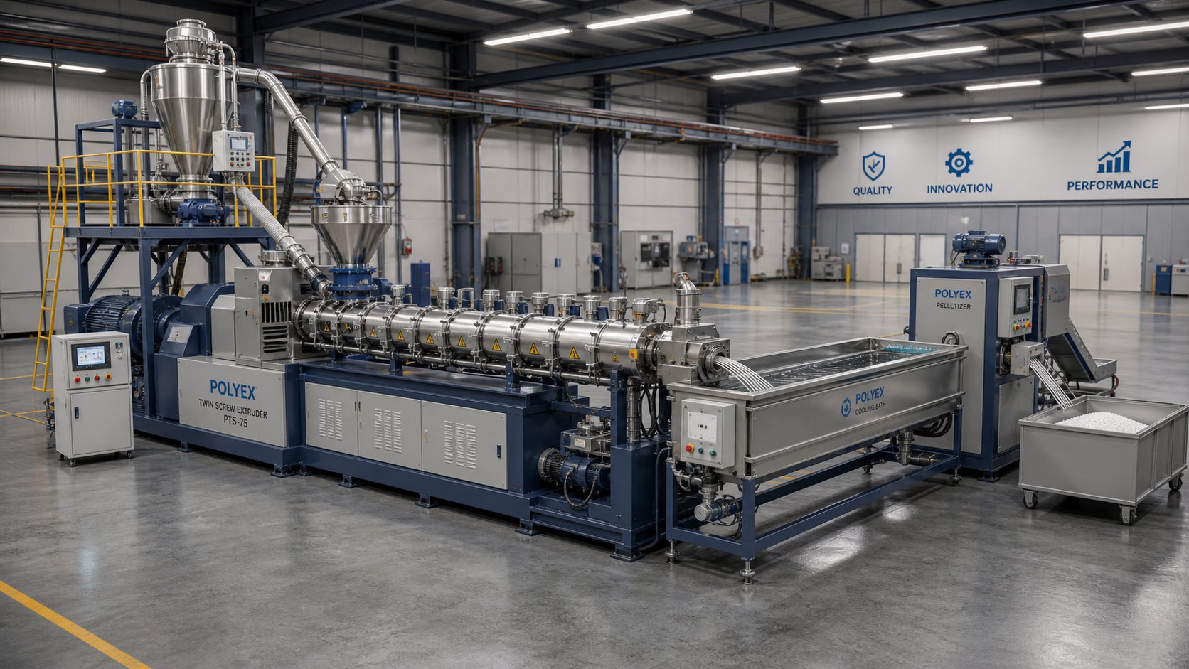
From Schematic Understanding to Production Line Reality
The extruder schematic ends at the die head, but a complete extrusion line schematic does not. Full-system process flow diagrams extend the drawing downstream, depicting every piece of equipment that transforms hot, unstable extrudate into a finished product ready for packaging and shipment. If your facility runs pipe, sheet, pelletizing, or recycling lines, understanding this extended portion of the schematic is just as critical as reading the barrel and screw sections upstream.
Downstream Equipment on Full-System Schematics
On a process flow diagram, downstream equipment appears as a series of sequential blocks connected by flow arrows running left to right from the die exit. Each block is labeled with the equipment type, and annotations typically include line speed, cooling medium, and dimensional control parameters. The standard downstream sequence follows a logical order: calibration and sizing first, then cooling, haul-off or pulling, and finally cutting, winding, or collection.
The specific downstream layout on the schematic varies significantly by product type. Here are the most common configurations you will encounter:
- Pipe lines — Vacuum calibration tank, spray cooling tanks, haul-off caterpillar puller, planetary chipless cutter, and pipe stacker or bundler.
- Profile lines — Calibration table with sizing blocks, cooling water bath, belt or caterpillar puller, flying saw or guillotine cutter, and stacking table.
- Sheet lines — Three-roll polishing stack (calender), cooling conveyor, edge trimmer, haul-off rolls, and sheet cutter or winder.
- Pelletizing lines — Strand die, water cooling bath, air knife dryer, strand pelletizer, and vibratory classifier — or alternatively, an underwater pelletizer or water-ring pelletizer shown as a single integrated block directly at the die face.
- Recycling lines — Screen changer with continuous filtration, degassing section, strand or underwater pelletizer, dewatering screen, and bulk bag filling station.
Each downstream station on the schematic functions as a quality gate. As noted in extrusion line references, calibration locks the geometry, cooling stabilizes it, haul-off controls wall thickness through speed regulation, and the cutter or winder defines the final delivery form. A problem at any station — worn calibration sleeves, insufficient cooling length, unstable puller speed — produces defects that are often misdiagnosed as extruder issues when the root cause sits entirely downstream.
Scale-Dependent Schematic Differences
Not every twin screw extruder schematic carries the same level of complexity. The scale of the machine dramatically shapes what you see on the drawing, from the number of barrel segments to the sophistication of auxiliary systems.
A laboratory twin screw extruder schematic — typically depicting machines with 11 mm to 16 mm screw diameters — shows the fewest barrel zones, often just six to eight segments. Downstream equipment may be as simple as a strand cooling trough and a manual pelletizer. Instrumentation annotations are minimal, and the gearbox block is compact. A lab scale twin screw extruder or benchtop twin screw extruder drawing fits on a single page because the machine itself is small enough to sit on a laboratory bench. These schematics prioritize flexibility and fast changeover over throughput, reflecting their role in formulation screening and R&D.
Pilot-scale schematics, covering screw diameters around 26 mm to 35 mm, add noticeable complexity. You will see side-feeder ports, vacuum venting sections, more temperature zones, and downstream pelletizing equipment drawn in greater detail. Instrumentation annotations expand to include melt pressure transducers, torque readouts, and gravimetric feeder controls. Scale-up research confirms that pilot machines bridge the gap between proving a formula works and confirming it can run under realistic production conditions — and their schematics reflect that intermediate complexity.
Production-scale schematics for machines with 50 mm to 92 mm or larger screw diameters are the most densely annotated drawings you will encounter. These include full automation control loops, multiple loss-in-weight feeders, redundant cooling circuits, complex gearbox lubrication systems, and complete downstream lines with in-line inspection and packaging systems. The P&ID version of a production schematic alone can span several sheets, with each sheet covering a different subsystem.
Applying Schematic Knowledge to Equipment Selection
Every section of this article has built toward one practical outcome: the ability to look at a twin screw extruder schematic and extract actionable information. Whether you are specifying a new machine, troubleshooting a persistent quality issue, training new operators, or sourcing replacement components, schematic literacy turns complex engineering drawings into decision-making tools.
When evaluating twin screw extruders for sale — whether new from twin screw extruder manufacturers or a used twin screw extruder on the secondary market — the schematic is your most reliable reference document. It tells you the exact barrel configuration, screw element layout, gearbox capacity, and thermal system design before you ever visit a factory floor. Comparing the schematic against your process requirements reveals whether a machine can handle your formulation, throughput target, and downstream integration needs, independent of the twin screw extruder price listed on a quotation.
For teams ready to move from schematic analysis to component sourcing, the following resources provide practical support:
- NANHAIYA Plastic Extruder Machine and Screw Barrel Support — Connects extrusion manufacturers, recycling plants, and technical teams with precision screw barrels, replacement elements, and technical consultation across pipe, profile, sheet, pelletizing, and recycling extrusion lines.
- OEM technical documentation departments — Most major manufacturers provide detailed schematic packages with equipment purchases; request both mechanical cross-sections and screw profile diagrams during the quotation phase.
- Industry standards libraries — ISO 10628 for process flow diagrams and ISA-5.1 for P&ID instrumentation symbols provide the conventions needed to read system-level schematics accurately.
A schematic diagram of a twin screw extruder is not a static reference poster to hang on a maintenance shop wall. It is a living document that guides equipment selection, process optimization, parts procurement, and operator training throughout the life of the machine. The more fluently your team reads it, the faster you solve problems, the more precisely you communicate with suppliers, and the more confidently you scale from laboratory trials to full production output.
Frequently Asked Questions About Twin Screw Extruder Schematics
1. What are the main types of twin screw extruder schematic diagrams?
Engineers typically work with four distinct schematic types: mechanical cross-sections showing internal components in cutaway view, screw profile diagrams mapping element sequences along the shaft, process flow diagrams (PFDs) illustrating material flow through the full line, and piping and instrumentation diagrams (P&IDs) detailing control loops, valves, and sensors. Each serves a different audience - cross-sections suit maintenance crews, profile diagrams guide process engineers, PFDs support project planning, and P&IDs are essential for commissioning and operations teams.
2. How do you read screw element codes on a twin screw extruder profile diagram?
Screw element codes follow a standardized format that encodes element type, pitch, length, and rotation direction. For example, SE 30/30 R indicates a screw element with 30 mm pitch, 30 mm length, and right-hand (forward) rotation. Kneading block codes like KBW 45/5/30 R specify the disc offset angle (45 degrees), number of discs (5), total length (30 mm), and conveying direction (R for forward). Understanding these codes allows you to map the entire processing recipe laid out on the shaft, from feed-zone conveying elements through mixing blocks to metering-zone pressure builders.
3. What is the difference between co-rotating and counter-rotating twin screw extruder schematics?
The quickest way to tell them apart is the cross-section view near the feed end. Co-rotating schematics show both rotation arrows pointing the same direction with a fully intermeshing, self-wiping figure-eight bore profile and L/D ratios typically between 32:1 and 56:1. Counter-rotating schematics display opposing rotation arrows with closely or partially intermeshing screws, and conical variants show a tapered barrel bore that narrows toward the die with L/D ratios around 10:1 to 26:1. Co-rotating machines dominate compounding applications, while counter-rotating designs are preferred for PVC pipe and profile extrusion.
4. What are the five functional zones shown on a twin screw extruder schematic?
Reading upstream to downstream, the five zones are: (1) feed zone, identified by the hopper symbol and large-pitch conveying elements; (2) melting-compression zone, marked by the transition to kneading blocks and rising temperature setpoints; (3) mixing-kneading zone, packed with kneading discs and mixing elements at the highest barrel temperatures; (4) metering zone, a uniform run of consistent-pitch conveyors building stable pressure; and (5) die head and shaping zone, showing the breaker plate, screen changer, and die geometry specific to the final product. Suppliers like NANHAIYA (nhyscrews.com) can help source the precision screw barrel components that populate each of these zones.
5. Why are twin screw extruder schematics more complex than single screw extruder drawings?
Twin screw schematics carry significantly more detail because the machine architecture itself is modular and multi-functional. Where a single screw drawing shows one continuous screw in a one-piece barrel with a simple gearbox, a twin screw schematic depicts numbered modular barrel segments with configurable ports, dozens of individually coded interchangeable screw elements on splined shafts, a torque-distributing gearbox synchronizing two output shafts, and multiple feed, vent, and injection locations. This complexity mirrors the twin screw extruder's superior mixing capability and process flexibility for compounding, reactive extrusion, and devolatilization tasks.
Written by
Nanhaiya Technical Team
Zhoushan Nanhaiya Plastic Machinery Co., Ltd.
The Nanhaiya technical team supports screw and barrel manufacturing projects through application review, technical communication, custom manufacturing coordination, and production and quality control.
Discuss Your Application
Related Articles
More insights on screw barrel technology and plastics processing.
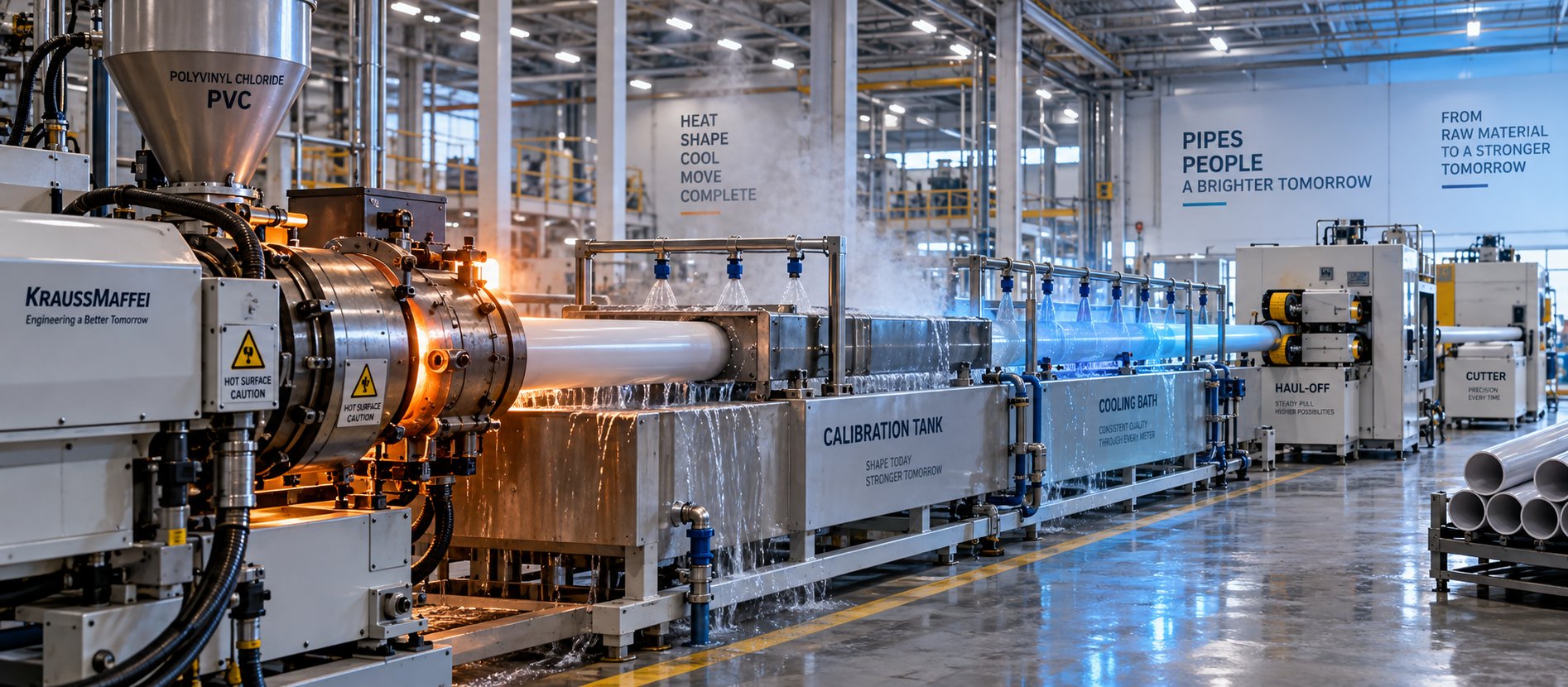
PVC Pipe Making Machine: What No Supplier Will Tell You First
Oct 21, 2026
Learn what a PVC pipe making machine really includes, how each component works, extruder types compared, maintenance schedules, defect fixes, and buying tips.
Read Article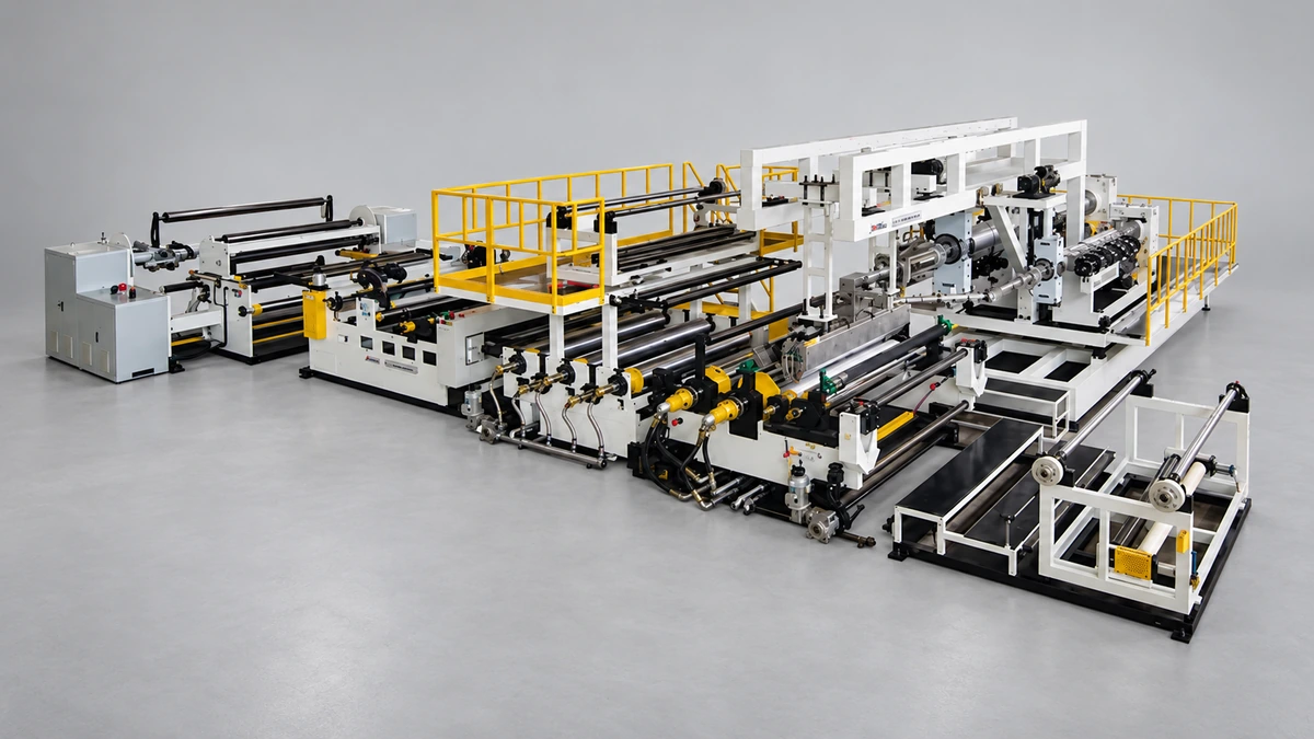
What Your Film Extrusion Machine Datasheet Won't Tell You
Oct 20, 2026
Film extrusion machine guide covering blown vs cast processes, multilayer configurations, screw specs, resin selection, and supplier evaluation for production engineers.
Read Article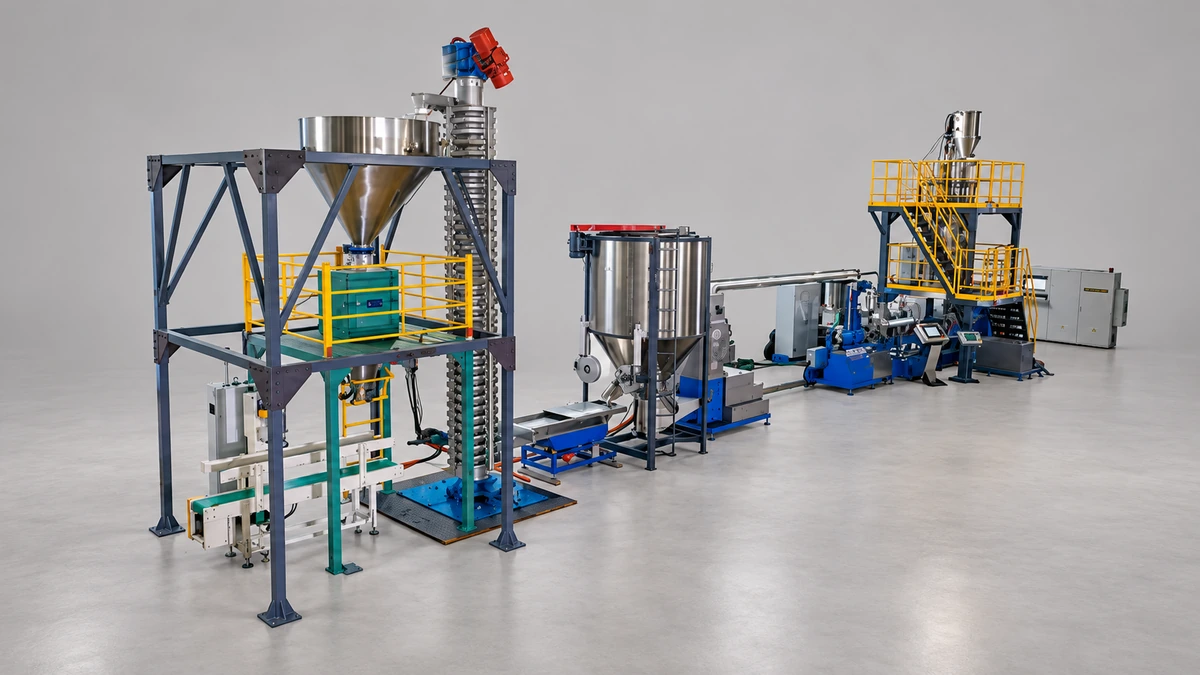
Raw Scrap to Perfect Pellets: Plastic Pelletizing Machine Guide
Oct 19, 2026
Learn how a plastic pelletizing machine converts scrap into uniform pellets. Covers cutting methods, extruder types, quality control, costs, and maintenance.
Read ArticleLooking for something else?
Search by material, symptom or product and jump straight to the relevant page.
These are navigation suggestions based on keyword matching — not a quotation, not a delivery commitment, and not a substitute for engineering review. Final specification is confirmed by our engineers against your drawings and processed material.
Need help with screw barrel selection?
Share your machine model, processed material and application. Our team can help with pricing and technical support.