

What a PVC Pipe Making Machine Actually Is and Why It Matters
When most people hear the term "PVC pipe making machine," they picture a single, imposing piece of equipment churning out finished pipes. That picture is incomplete — and it leads to costly purchasing mistakes. In reality, the term refers to an entire integrated production line, a synchronized chain of specialized units that transforms raw PVC compound into dimensionally precise, ready-to-ship pipes. Understanding this distinction is the first step toward making informed decisions about equipment, capacity, and long-term profitability.
What Is a PVC Pipe Making Machine
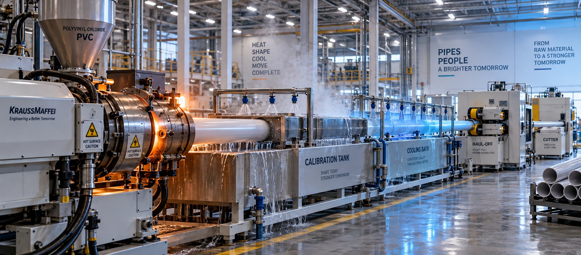
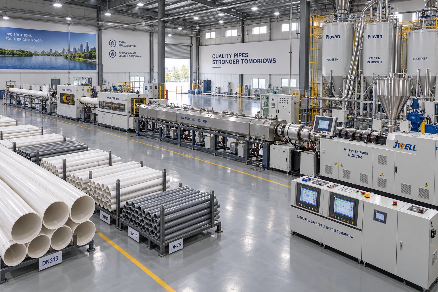
A PVC pipe making machine is a continuous extrusion production system composed of multiple interdependent units, each responsible for a specific stage of pipe formation. The core PVC pipe production line components include:
- Conical twin-screw extruder — melts and homogenizes the PVC dry blend
- Die head — shapes the molten polymer into a hollow tubular profile
- Vacuum calibration tank — locks the pipe's outer diameter to precise tolerances
- Spray and immersion cooling tanks — gradually solidify the pipe while minimizing internal stress
- Haul-off unit — pulls the pipe through the line at a controlled, constant speed
- Cutting unit — slices the continuous pipe into predetermined lengths
- Belling machine and stacker — forms socket ends (when needed) and collects finished sections
Every unit in this chain must operate in tight coordination. The extruder's output rate, the haul-off speed, the vacuum level in the calibration tank, and the cutter's cycle time all influence one another. Change one parameter without adjusting the others, and you'll see wall-thickness drift, surface defects, or dimensional failures almost immediately. This is why PVC pipe manufacturing equipment is best understood — and evaluated — as a complete system rather than a collection of standalone machines.
Why PVC Pipe Production Matters
PVC remains one of the most widely used piping materials on the planet, and for good reason. It is lightweight, corrosion-resistant, cost-effective, and durable enough to last over 100 years in underground installations. From potable water distribution and sewer systems to electrical conduit and agricultural irrigation networks, PVC pipes serve as the backbone of modern infrastructure worldwide.
For manufacturers, engineers, and procurement teams, this widespread demand creates significant business opportunity — but also raises the stakes. Choosing the wrong line configuration, underestimating capacity needs, or overlooking wear-critical components can erode margins quickly. Whether you are launching a new production facility, expanding capacity for rigid pressure pipes, or diversifying into drainage and conduit lines, a thorough understanding of how PVC pipe machines work is not optional — it is essential.
A PVC pipe making machine's output quality depends on the precise coordination of every component in the line, not any single unit alone. Evaluating an extruder in isolation, without considering the die head, calibration tank, haul-off, and controls that surround it, is the most common mistake buyers make.
This article goes beyond the glossy spec sheets. It covers the full manufacturing ecosystem — from raw-material intake to finished pipe — and reveals the technical details, maintenance realities, and selection criteria that most suppliers leave out of the conversation. The differences between pipe types, extruder architectures, and downstream configurations can dramatically affect your production economics, and those differences start with the specific type of PVC pipe you intend to produce.
Types of PVC Pipes and How Machine Requirements Differ
Not all PVC pipes are created equal — and neither are the machines that produce them. This is one of the most overlooked realities in the industry. A production line configured for rigid UPVC drainage pipe will not perform well if you feed it a CPVC hot-water compound, and it certainly cannot produce molecularly oriented PVC-O pipe without major additions. Yet most equipment listings present a single generic "PVC pipe line" as though one size fits all. It doesn't. The pipe type you plan to manufacture dictates your formulation, your temperature profile, your screw and barrel metallurgy, and even your downstream line speed.
UPVC and CPVC Pipe Production Differences
UPVC — unplasticized polyvinyl chloride — is the workhorse of the PVC pipe world. It is rigid, cost-effective, and used everywhere from cold-water pressure mains to underground sewer systems. Because no plasticizers are added to the formulation, the material retains high mechanical strength and chemical resistance. Processing temperatures for UPVC typically fall in the range of 170 °C to 200 °C, which is well within the comfort zone of standard nitrided steel screws and barrels.
CPVC changes the equation significantly. Produced by post-chlorinating PVC resin — raising chlorine content from roughly 57% to as high as 69% — CPVC gains a much higher heat-deflection temperature, making it suitable for hot-water distribution and industrial chemical piping. But that higher thermal resistance cuts both ways during extrusion. CPVC pipe production temperature requirements push barrel zone setpoints to 190 °C–230 °C, and the material's higher melt viscosity demands greater torque from the drive system.
What does this mean for the machine? Three critical changes stand out when comparing UPVC vs CPVC pipe machine differences:
- Barrel and screw metallurgy — CPVC's elevated chlorine content generates more corrosive byproducts during processing. Standard nitrided barrels may pit prematurely, so corrosion-resistant bimetallic linings or specialized alloy steels are strongly recommended.
- Temperature control precision — Because CPVC sits closer to its degradation threshold, tighter PID temperature control with faster response times becomes essential to prevent localized overheating and material discoloration.
- Drive torque and screw design — The stiffer melt requires higher torque at lower screw speeds, often necessitating a gearbox upgrade or a conical twin-screw extruder with a higher torque rating than what a comparable UPVC line would need.
Formulation chemistry deepens the divide further. A typical UPVC drainage pipe compound may contain high levels of calcium carbonate (CaCO3) filler to reduce material cost, while a UPVC pressure pipe leans on impact modifiers and processing aids for toughness. CPVC formulations, in contrast, use different stabilizer systems — typically organotin or calcium-zinc based — engineered to handle the higher processing window without degradation. Each of these recipe variations affects screw flight geometry, compression ratios, and die land lengths.
PVC-O and Conduit Pipe Considerations
PVC-O — molecularly oriented PVC — represents a fundamentally different approach. Imagine taking a standard UPVC pressure pipe and stretching it at a controlled temperature so that the polymer chains align in both the circumferential and axial directions. The result is a bi-oriented pipe with dramatically improved tensile strength, impact resistance, and fatigue performance, all while using less raw material per meter.
The production process starts conventionally: a UPVC preform is extruded using a standard twin-screw line. The real difference lies in what happens next. The preform is reheated to a precise window — typically 85 °C to 100 °C — and then expanded using internal pressure to achieve a diameter stretching ratio between 1.6 and 2.1. Higher ratios yield higher minimum required strength (MRS) values. Rapid cooling locks in the new molecular alignment. This inline orientation step requires specialized PVC-O pipe extrusion equipment — expansion dies, precise reheating zones, and advanced cooling systems — that simply does not exist on a standard pipe line.
PVC electrical conduit sits at the opposite end of the complexity spectrum. Conduit pipes feature thinner walls, smaller diameters, and relatively simple formulations. A PVC conduit pipe making machine prioritizes line speed and fast changeovers over the tight wall-thickness tolerances demanded by pressure-rated pipe. Downstream equipment can be shorter since thinner walls cool faster, and the haul-off unit runs at higher speeds — sometimes exceeding 20 meters per minute — to maximize throughput on a product with slim per-meter margins.
| Pipe Type | Typical Application | Processing Temp Range | Key Machine Differences |
|---|---|---|---|
| UPVC (Rigid) | Cold-water pressure mains, drainage, sewerage | 170 °C – 200 °C | Standard nitrided screw/barrel; moderate torque; formulation varies by end use (high filler for drainage, impact modifiers for pressure) |
| CPVC | Hot-water distribution, industrial chemical piping | 190 °C – 230 °C | Corrosion-resistant bimetallic barrel linings; higher torque gearbox; tighter PID temperature control; specialized stabilizer-compatible screw design |
| PVC-O (Bi-Oriented) | High-performance pressure pipe for water transmission | 85 °C – 100 °C (orientation stage) | Standard UPVC extrusion plus inline reheating, expansion, and rapid-cooling modules; diameter stretching ratio 1.6–2.1 |
| PVC Conduit | Electrical wiring protection, telecommunications | 170 °C – 195 °C | Higher line speeds; shorter cooling baths; fast die changeovers; wall-thickness tolerance less critical than for pressure pipe |
These differences are not trivial details buried in engineering manuals — they are the first decisions that shape your entire capital investment. Choosing a machine configuration without mapping it to your target pipe type is like buying a vehicle before deciding whether you need a delivery truck or a sedan. The mechanical heart of any configuration, however, remains the extrusion process itself — and understanding that process stage by stage reveals exactly where quality is won or lost.
Step-by-Step PVC Pipe Extrusion Process Explained
Picture a continuous relay race where every runner must match the pace of the one before — speed up too much and the baton drops, slow down and the whole team stalls. That is precisely how PVC pipes are manufactured. Each station in the production line hands off a progressively more refined product to the next, and the coordination between them determines whether you end up with a flawless pipe or a reject pile. Surprisingly, few equipment suppliers walk buyers through this sequence in meaningful detail. What follows is a complete, stage-by-stage breakdown of the PVC pipe extrusion process — the kind of clarity that turns a first-time operator into an informed decision-maker.
- Dry-blend preparation and feeding — The process begins before the extruder even starts. PVC resin powder is pre-mixed in a high-speed hot/cold mixer with stabilizers, lubricants, fillers, pigments, and processing aids to create a homogeneous dry blend. This compound is then loaded into the extruder's hopper, which feeds it into the barrel at a controlled rate. Consistent dosing matters enormously here; starving or overfeeding the screw disrupts everything downstream. Gravimetric feeders or volumetric dosing systems help maintain a steady mass flow, especially when the formulation includes variable-density additives like calcium carbonate.
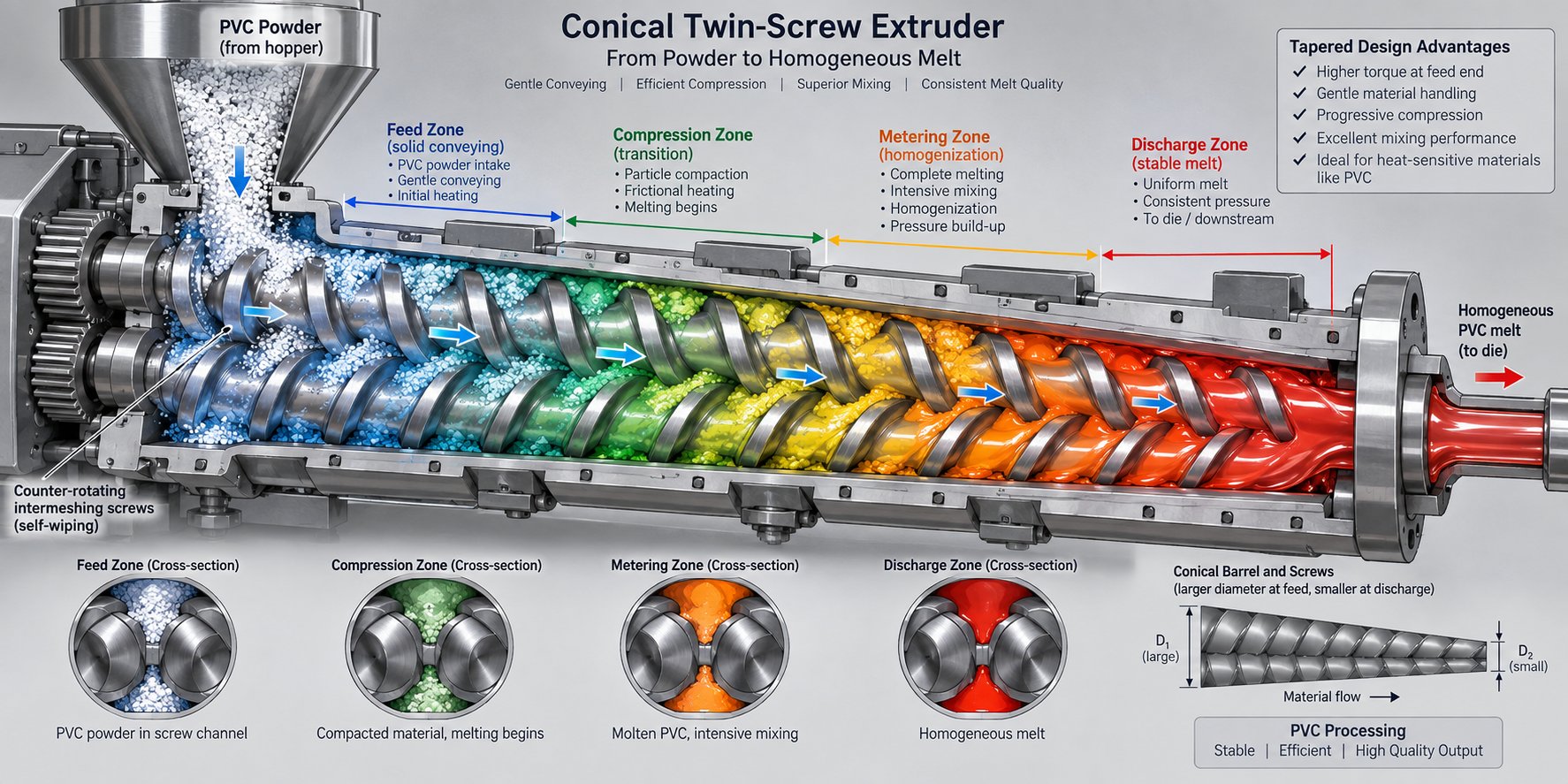
- Plasticizing and homogenizing inside the barrel — Once inside the barrel, the rotating screw flights convey the PVC powder forward through multiple heating zones. Each zone is set to a progressively higher temperature — typically rising from around 155 °C near the feed throat to 180 °C–190 °C at the metering section for standard UPVC. As the material moves forward, a combination of conducted heat from barrel heaters and frictional shear from the screw flights compresses, melts, and homogenizes the compound. By the end of the barrel, the PVC has transformed from a loose powder into a dense, uniformly plasticized melt. The screw speed, compression ratio, and barrel zone temperatures must be carefully balanced: too much shear or excessive temperature and the thermally sensitive PVC begins to degrade, releasing hydrogen chloride gas and discoloring the product.
- Melt conveyance through the die head — The homogenized melt is pushed under pressure into the die head, where it is shaped into a hollow tubular profile. Inside the die, a mandrel forms the pipe's inner bore while the outer die ring defines the external surface. The design of the die — whether spider-type or spiral-mandrel — determines how evenly the melt distributes around the circumference. A well-designed die eliminates weld lines and thickness imbalances before the pipe even exits the tooling. Die temperature is independently controlled, typically held a few degrees above the final barrel zone, to ensure smooth melt flow without stagnation.
- Vacuum calibration to lock outer diameter — This is the stage where precision is made or lost. The soft, still-pliable tube emerging from the die enters a vacuum calibration tank within centimeters of the die exit. Inside the tank, a stainless-steel calibration sleeve matches the target outer diameter. Vacuum pressure — carefully regulated — pulls the hot pipe wall outward against the sleeve, locking the OD to tight tolerances. Simultaneously, chilled water begins cooling the outer surface. The calibration step is widely regarded as the first true quality gate on the line: if the pipe loses roundness or drifts on diameter here, no downstream station can correct it. Vacuum level, water temperature, and the condition of the sizing sleeve all interact to determine dimensional accuracy.
- Spray and immersion cooling — After initial calibration, the pipe passes through one or more cooling tanks where spray nozzles and immersion baths progressively extract residual heat. The goal is to solidify the pipe uniformly — inside wall as well as outside — so that internal stresses do not cause warping, bowing, or post-production dimensional changes after stacking. Cooling length is directly proportional to pipe wall thickness and line speed: thick-walled, large-diameter pressure pipes need substantially longer cooling baths than thin-walled conduit. Rushed cooling is one of the most common causes of hidden quality problems that only surface hours or days after production.
- Haul-off to maintain consistent wall thickness — A caterpillar-track or belt-type haul-off unit grips the cooled pipe and draws it through the entire downstream line at a precisely controlled speed. This is where wall thickness is effectively fine-tuned. The relationship is straightforward: if haul-off speed increases relative to extruder output, the pipe stretches and the wall thins; if it decreases, material accumulates and the wall thickens. Even minor speed oscillations — caused by worn pads, unstable clamping pressure, or drive inconsistencies — produce repeating thick-thin patterns along the pipe length. The haul-off speed must be tightly synchronized with extruder output, and most modern lines use closed-loop servo or inverter-driven control to keep this ratio stable.
- Cutting to length — The continuous pipe is cut into predetermined lengths by a planetary saw or chip-free cutter. A planetary cutter orbits around the pipe, slicing through the wall without generating chips and producing a clean, perpendicular end face — ideal for socket jointing. Chip-free cutters accomplish the same result by collapsing a blade ring inward. The cutting station tracks with the moving pipe so the line never needs to stop, and length accuracy is governed by an encoder or metering wheel synchronized with the haul-off.
- Socketing (belling) and stacking — For pipes that require integral socket joints — common in pressure and drainage applications — a belling machine reheats one end of the cut pipe, inserts it into a mold, and expands it with air pressure or a mandrel to form the bell shape. Finally, an automatic stacker collects finished pipe lengths, arranges them in layers, and bundles them for storage or transport. This last step may seem minor, but careless stacking of still-warm pipes can introduce ovality that only becomes apparent during installation.
From Raw Material Feeding to Melt Plasticization
Stages one and two deserve a closer look because they represent the "invisible" half of quality control — problems originating here often do not reveal themselves until the pipe is already cooling downstream. When PVC dry blend enters the hopper, the screw's feed section — where flight depth is greatest — conveys powder at low pressure into the barrel. As the material advances into the compression zone, the decreasing channel depth forces the powder particles together, expelling trapped air back toward the feed throat or out through a vacuum vent port.
Barrel heating zones work in concert with this mechanical compression. The first zone gently preheats the compound to prevent thermal shock. Subsequent zones raise the temperature progressively until the PVC reaches its ideal melt temperature — typically 160 °C to 190 °C, depending on the formulation. For rigid PVC processed on a conical twin-screw extruder, the converging screw geometry provides intense mixing at relatively low rotational speeds, which is critical for a polymer as heat-sensitive as PVC. The result is thorough gelation — meaning the PVC particles are fully fused into a homogeneous melt — without the excessive residence time or localized hot spots that trigger degradation.
You'll notice that experienced operators pay close attention to motor current during this phase. A sudden spike in amperage can signal a cold slug of unmelted material or a formulation inconsistency, while a gradual upward trend over weeks or months often indicates screw and barrel wear — the clearance between screw flight and barrel wall has widened, reducing plasticizing efficiency and forcing the motor to work harder to maintain output.
Vacuum Calibration, Cooling, and Downstream Operations
Once the plasticized melt exits the die as a soft, hot tube, it enters the most dimensionally sensitive section of the entire line. The vacuum calibration process is deceptively simple in concept — pull the pipe wall outward against a precision sleeve — but the execution demands tight control of multiple interacting variables. Vacuum too low, and the pipe undersizes or goes oval. Vacuum too high, and the outer surface can drag against the sleeve, creating scoring or uneven stress. Water temperature in the calibration tank matters just as much: colder water freezes the outer skin faster, which can trap heat inside the wall and cause delayed shrinkage after the pipe leaves the line.
Downstream of calibration, the spray and immersion cooling tanks complete the solidification process. Imagine a pipe with a 10 mm wall thickness running at several meters per minute — the inner surface is still well above softening temperature even after the outer surface has hardened. Insufficient cooling length creates pipes that look perfect at the cutter but develop subtle bowing or diameter shifts once they reach ambient temperature on the storage rack.
The haul-off unit is the line's speed governor, and its influence on final quality is routinely underestimated. Wall variation commonly traces back to puller stability, not the extruder. Even a two-percent fluctuation in haul-off speed translates directly into a measurable wall-thickness deviation — something that pressure-testing will immediately flag. Modern caterpillar haul-offs with servo drives and automatic contact-pressure adjustment mitigate this risk, but the fundamentals remain unchanged: the balance between melt delivery and take-off speed is the single most important ratio on the entire production line.
Finally, the cutting and stacking stages close the loop. Whether a planetary saw or chip-free cutter is used, the key requirement is synchronization with line speed so that every cut is perpendicular and length tolerance stays within specification. Socketing, when required, adds a secondary heating and forming step that must be carefully managed to avoid weakening the pipe end.
Every PVC pipe production stage — from hopper feeding through final stacking — is linked by a chain of cause and effect. A temperature deviation at the barrel cascades into calibration problems, which surface as dimensional rejects at the cutter. Understanding this chain is what separates a productive line from a troubleshooting exercise.
With the full extrusion sequence mapped out, a natural question follows: what exactly makes each of these components perform well or poorly? The answer lies in the engineering details — screw geometry, die design, motor class, and control architecture — that separate a reliable production line from one that constantly demands attention.
Critical Machine Components and Why Specifications Matter
Spec sheets list numbers — screw diameter, motor kilowatts, tank length — but they rarely explain why those numbers matter or what happens when they are wrong. Two production lines with nearly identical data sheets can deliver dramatically different pipe quality, energy costs, and maintenance burdens depending on the engineering behind each component. This is where buying decisions are truly won or lost: not in the headline figures, but in the design choices, materials, and control systems that determine how those figures translate into real-world performance.
Extruder, Die Head, and Calibration Tank
The extruder is the mechanical heart of the entire line. Its primary job is to accept PVC dry blend and deliver a perfectly homogenized, thermally uniform melt to the die head — and it accomplishes this through the precise interaction of screw geometry, barrel heating, and drive torque. Two parameters define the extruder's character more than any others: the screw and barrel.
Why do these components deserve so much attention? Because they form the most wear-sensitive pair in the system. Every kilogram of PVC compound that passes through the barrel — especially formulations loaded with calcium carbonate filler or glass fiber — abrades the screw flight crests and the barrel inner wall. As the clearance between screw and barrel widens, plasticizing efficiency drops, melt pressure becomes erratic, and the motor draws more current to compensate. PVC extruder screw and barrel metallurgy is the primary defense against this inevitable degradation.
Standard nitrided steel barrels perform well for unfilled or lightly filled UPVC formulations, extending usable life through a hard nitrogen-diffused surface layer. Higher-demand applications, however, call for bimetallic screw barrels — a composite construction where a high-strength alloy steel substrate is lined with a wear-resistant and corrosion-resistant alloy layer, typically nickel-based or tungsten-based, applied through centrifugal casting. This bimetallic approach extends barrel life by up to three to five times compared to nitrided barrels, while also resisting the chemical corrosion caused by hydrogen chloride released during PVC processing. For lines running CPVC or heavily filled compounds, bimetallic construction is not a luxury — it is a practical necessity for predictable service intervals and stable melt quality.
Downstream of the extruder, the die head shapes the melt into a tubular profile. Two dominant PVC pipe machine die head types exist, each with distinct advantages:
- Spider die — Features radial "legs" that hold the mandrel in place, creating a central, symmetrical feed of the melt. Spider dies are favored for PVC pipe because they offer a short residence time — critical for a thermally sensitive polymer that degrades quickly at elevated temperatures. The trade-off is visible weld lines where the melt sectors, separated by the spider legs, recombine. However, modern die engineering has largely solved this: greater melt deformation after the spider legs energizes polymer molecules to cross the weld boundary, producing strong spider-line welds without the need for excessive die pressure or long land lengths.
- Spiral-mandrel die — Uses helical channels carved into the mandrel to distribute the melt in an overlapping spiral pattern. This design virtually eliminates weld lines and produces very uniform wall-thickness distribution around the circumference. The downside is a longer flow path, which increases residence time — a concern for heat-sensitive PVC, particularly at larger diameters where the melt volume inside the die is substantial. Spiral-mandrel dies tend to be more complex and costlier to manufacture, and are often selected for polyolefin pipes (HDPE, PP) where thermal sensitivity is less of a constraint, though they can be engineered for PVC with careful thermal management.
Choosing between them is not about one being universally "better." For most rigid PVC pipe diameters, a well-designed spider die delivers the ideal balance of short residence time, manageable back pressure, and sufficient weld-line strength. Spiral-mandrel dies become attractive when wall-thickness uniformity is paramount and the formulation can tolerate the slightly longer exposure to heat.
The vacuum calibration tank for PVC pipe is where dimensional precision is physically locked in. Imagine the soft tube emerging from the die — it has shape, but that shape is not yet permanent. Within the calibration tank, a precision-machined stainless-steel sizing sleeve defines the target outer diameter, while regulated vacuum pressure draws the pipe wall outward against the sleeve surface. Simultaneously, chilled water sprays begin solidifying the outer skin.
Three factors govern how well this unit performs:
- Sleeve accuracy and condition — A worn or scored sleeve imprints surface defects onto every meter of pipe that passes through it. Regular inspection and timely replacement are non-negotiable.
- Vacuum precision — Small fluctuations in vacuum level translate directly into OD variation. Quality tanks use closed-loop vacuum regulation rather than simple on/off valves.
- Effective cooling length — The longer the contact between pipe and sizing sleeve under vacuum, the more firmly the diameter is set before the pipe moves into the free-cooling baths. Undersized tanks — common in budget lines — sacrifice this contact length, and the result shows up as pipes that drift out of spec, especially at higher line speeds or with thicker walls.
The haul-off unit operates as the line's speed governor. Two main types exist: caterpillar-track haul-offs and belt-type haul-offs. Caterpillar designs grip the pipe with opposing rubber-padded chains or tracks and are the dominant choice for rigid PVC pipe. They provide strong, evenly distributed clamping force that prevents slippage even on heavy large-diameter pipes. Belt-type haul-offs use wide, flat belts and are sometimes preferred for softer profiles or smaller-diameter tubing where lighter contact pressure is needed.
What matters most in either design is speed stability. The haul-off speed divided by the extruder output rate defines the draw-down ratio — and that ratio directly controls wall thickness. A servo-driven haul-off with closed-loop feedback delivers the kind of speed consistency (typically within ±0.1%) that keeps wall-thickness variation inside specification limits. Hydraulic or open-loop drives simply cannot match this precision, and the difference shows up immediately in reject rates and material waste.
Finally, the cutting unit completes the mechanical chain. Planetary saws rotate a circular blade around the moving pipe, producing a clean, chip-free, perpendicular cut without stopping the line. They are the standard for medium- to large-diameter rigid PVC pipe. Chip-free cutters — where a blade ring collapses inward to shear through the wall — are common for smaller diameters and conduit, where speed and the absence of swarf contamination take priority. In both cases, the cutter must track with line speed via an encoder or laser sensor so that length accuracy remains within tolerance across thousands of consecutive cuts.
Electrical and Control Systems That Affect Performance
If the extruder, die, and downstream equipment form the body of a PVC pipe production line, the electrical and control systems are its nervous system. Skimping here is tempting — motors and inverters are not as visually impressive as a gleaming calibration tank — but the consequences ripple through every aspect of production, from energy bills to reject rates.
Consider the main drive motor. A PVC pipe extruder runs continuously, often 20 or more hours per day, making motor efficiency one of the largest ongoing cost factors. The difference between efficiency classes is real and quantifiable. A peer-reviewed study comparing IE2, IE3, and IE4 induction motors on a 75 kW industrial drive found that upgrading from an IE2 motor to an IE4 motor saved 192.6 MWh of energy over a 20-year service life, with a payback period of just 2.9 years. The IE4 motor also avoided 8.87 tons of CO2 emissions per year — 2.35 times more than the IE3 alternative. For a pipe extrusion line running three shifts, these savings compound substantially over the equipment's lifespan. Specifying an IE3 or IE4 motor is not merely a "green" checkbox — it is a direct reduction in cost per kilogram of pipe produced.
Quality inverter drives (variable frequency drives, or VFDs) matter equally. The inverter controls screw speed with precision, and its response characteristics determine how quickly the system compensates for load fluctuations — such as a brief inconsistency in raw-material feeding or a temperature-induced change in melt viscosity. A well-tuned inverter maintains screw RPM within a fraction of a percent, which translates to steady melt pressure and, ultimately, consistent pipe dimensions.
PID temperature controllers round out the critical control trio. Every barrel zone, the die head, and the calibration tank rely on precise temperature regulation. A PLC control system for the pipe extrusion line ties all of these inputs together — screw speed, barrel zone temperatures, vacuum levels, haul-off speed, cutter timing — into a coordinated process managed from a single HMI (human-machine interface) panel. Modern PLCs also log process data continuously, enabling operators to trace any quality deviation back to the exact parameter that drifted, turning reactive firefighting into proactive trend monitoring.
Here is a quick-reference summary of the key components and their primary functions:
- Conical twin-screw extruder — Plasticizes and homogenizes PVC dry blend into uniform melt
- Screw and barrel (nitrided or bimetallic) — Primary wear pair; metallurgy determines service life and melt consistency
- Die head (spider or spiral-mandrel) — Shapes melt into tubular profile; design affects wall-thickness uniformity and residence time
- Vacuum calibration tank — Locks outer diameter to target tolerance using vacuum pressure and chilled water
- Haul-off unit (caterpillar or belt) — Controls line speed and draw-down ratio; directly governs wall thickness
- Planetary saw or chip-free cutter — Cuts continuous pipe to length without stopping the line
- IE3/IE4 main drive motor — Reduces energy consumption and lowers cost per kilogram of output
- Inverter drive (VFD) — Maintains precise screw speed for stable melt pressure and output rate
- PID temperature controllers — Regulate barrel, die, and cooling zone temperatures within tight tolerances
- PLC with HMI — Centralizes process control, enables data logging, and supports real-time parameter monitoring
The components that appear on spec sheets are the same across most suppliers. The difference between a productive line and a problematic one lies in the engineering quality behind each component — screw metallurgy, die flow design, motor efficiency class, and control-loop precision.
Each of these components interacts with the others, but none defines the character of a PVC pipe production line more fundamentally than the extruder itself. And within the extruder category, the choice of architecture — single screw, parallel twin screw, or conical twin screw — shapes everything from plasticizing quality to energy consumption and output capacity.
Extruder Types for PVC Pipe Production Compared
Here is a question that trips up many first-time buyers: if the extruder is the heart of a PVC pipe making machine, why do three fundamentally different extruder architectures exist — and which one actually belongs on your production floor? The answer is not as simple as picking the most expensive option or the one with the highest output number. Each architecture — single screw, parallel twin screw, and conical twin screw — was engineered to solve different processing challenges, and rigid PVC pipe happens to be one of the most demanding applications in all of plastics extrusion. Choosing the wrong type does not just reduce efficiency; it can make stable production nearly impossible.
Single Screw vs. Parallel Twin Screw vs. Conical Twin Screw
Think of these three extruder types as tools built for different jobs that share a common name. They all convey, melt, and pressurize polymer — but the way they accomplish each task, and how well they handle the thermal sensitivity of rigid PVC, varies enormously.
A single-screw extruder is the simplest and most affordable architecture. One helical screw rotates inside a heated barrel, conveying material forward through friction between the polymer and the barrel wall. Single-screw machines work well for polymers that arrive pre-compounded as pellets — polyethylene, polypropylene, flexible PVC — because the material has already been plasticized once and flows relatively easily. For rigid PVC dry-blend powder, however, single-screw designs face a fundamental limitation: they rely heavily on barrel-wall friction to move material forward, and dry PVC powder has inconsistent frictional behavior. The result is uneven feeding, less thorough mixing, and a narrower processing window. Single screws still find use in softer PVC compounds, recycled PVC pellet processing, and some lower-output pipe applications, but they are rarely the first choice for high-volume rigid PVC pipe production.
A parallel twin-screw extruder steps up the mixing game significantly. Two screws of identical diameter sit side by side at a fixed center distance, typically co-rotating and intermeshing. This co-rotating design creates an "infinity-loop" flow pattern that continuously exchanges material between the two screws, delivering intensive distributive and dispersive mixing far beyond what a single screw can achieve. Parallel twin screws excel at compounding — blending polymers with fillers, pigments, glass fibers, and additives — and they dominate applications like masterbatch production, engineering plastics, and cable compounds. Their typical operating speed of 400-900 RPM delivers high throughput, and their modular screw element design allows rapid reconfiguration for different formulations.
So why are parallel twin screws not the default for rigid PVC pipe? Two reasons. First, the high rotational speeds that drive their throughput advantage also generate substantial shear heat — a serious liability for PVC, which begins degrading at temperatures that many other polymers handle comfortably. Second, the constant-diameter screw geometry does not naturally build the high discharge pressure that pipe dies demand. Parallel twin-screw extruder PVC applications tend to center on PVC compounding and pelletizing rather than direct pipe extrusion.
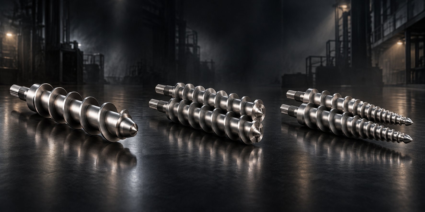
The conical twin-screw extruder was purpose-built for exactly the challenge rigid PVC presents. Its two counter-rotating screws taper from a large diameter at the feed end to a smaller diameter at the discharge. This converging geometry is the key to everything: at the inlet, the large screw diameter creates a wide, deep channel that accepts bulky PVC powder with high volumetric efficiency. As material advances toward the smaller outlet, the progressively narrowing channel compresses and pressurizes the melt — naturally building the discharge pressure needed to push material through a pipe die, without relying on extreme screw speed. Typical operating speeds for conical twin-screw extruders sit between 30 and 150 RPM, generating exceptional torque with minimal shear-induced heat.
This low-speed, high-torque processing philosophy is precisely what heat-sensitive rigid PVC demands. The counter-rotating intermeshing screws form closed C-shaped chambers that convey material in a positive, piston-like fashion, providing gentle but thorough plasticization and excellent self-cleaning. The result is a uniform, well-gelled melt delivered at high pressure and low temperature — the exact combination that produces dense, defect-free pipe walls.
| Extruder Type | Best Application | Advantages | Limitations |
|---|---|---|---|
| Conical Twin Screw | Rigid PVC pipe, profile, board, and WPC extrusion | High torque at low speed (30-150 RPM); natural pressure buildup from tapered geometry; gentle processing minimizes thermal degradation; excellent powder feeding; superior self-cleaning; screws can be advanced to compensate for wear | Fixed taper geometry limits L/D flexibility; lower maximum throughput compared to high-speed parallel designs; primarily suited to PVC and similar heat-sensitive materials |
| Parallel Twin Screw (Co-rotating) | Compounding, masterbatch, engineering plastics, PVC pelletizing | Intensive mixing via co-rotating intermeshing; high throughput at 400-900 RPM; modular screw elements for flexible configuration; excellent for multi-component blending and reactive extrusion | High shear heat generation problematic for thermally sensitive PVC; lower natural pressure buildup; higher capital cost and energy consumption; less effective with dry powder feeding for direct extrusion |
| Single Screw | Pre-compounded pellets, flexible PVC, recycled material reprocessing | Simplest design; lowest capital cost; adequate for pre-plasticized feedstock; easier operation and maintenance; well-suited for polyolefin pipe extrusion | Poor mixing for dry-blend powder; relies on friction-dependent conveying; narrow processing window for rigid PVC; inconsistent plasticization with multi-component formulations |
The comparison makes it clear why a conical twin-screw extruder for PVC pipe has become the industry standard worldwide. For manufacturers running rigid UPVC or CPVC pipe, profile, board, or foam board lines, the conical architecture delivers the best match between processing demands and mechanical capability. That said, the extruder frame is only half the story — the screws and barrel inside it determine whether that capability is fully realized or gradually eroded.
Why Conical Twin Screw Barrels Are Preferred for Rigid PVC
Imagine two identical conical twin-screw extruders installed side by side, running the same UPVC pipe formulation at the same screw speed. One produces pipe with smooth surfaces, consistent wall thickness, and stable output hour after hour. The other delivers rough inner surfaces, fluctuating motor current, and gradually declining output that forces the operator to compensate with higher temperatures — which, in turn, causes yellowing and micro-degradation. What is the difference? Almost always, it comes down to the conical twin screw barrel and screws themselves: their dimensional precision, metallurgical quality, and wear condition.
The converging geometry advantage of conical screws only works as designed when the clearance between screw flight and barrel wall is held within tight tolerances — typically fractions of a millimeter. As that clearance opens due to wear, several things happen simultaneously:
- Melt back-leakage increases — Plasticized material flows backward through the widened gap instead of moving toward the die, reducing effective output and destabilizing melt pressure.
- Mixing efficiency declines — The shearing action between flight crest and barrel wall that helps homogenize the PVC compound loses intensity, producing a less uniform melt with ungelated particles.
- Energy consumption rises — The motor must work harder to maintain the same throughput, drawing more current and accelerating drive-component wear.
- Product quality drifts — Rough inner surfaces, wall-thickness variation, and inconsistent density become progressively worse, and the operator's natural response — increasing barrel temperatures — only masks the symptom while creating new problems like thermal degradation.
This is why the conical twin screw barrel for rigid PVC is not just a commodity replacement part — it is the single most impactful wear component on the entire production line. The barrel's inner bore profile must match the screw taper precisely, and its surface must resist both the abrasive wear from filled compounds and the corrosive attack from hydrogen chloride gas released during PVC processing. High-quality barrels use nitrided alloy steel or bimetallic linings to deliver both hardness and chemical resistance, and the bore is honed to mirror-finish tolerances to ensure uniform melt conveyance from feed to discharge.
Manufacturers seeking custom or replacement conical twin screw barrels — such as those offered by NANHAIYA — can achieve more stable plasticization and extended production uptime by ensuring dimensional accuracy and metallurgical consistency in the replacement components. NANHAIYA serves PVC pipe, PVC profile, PVC board, foam board, and WPC extrusion manufacturers with barrels engineered to match OEM taper specifications, which means the new barrel integrates seamlessly with existing screw sets and gearbox assemblies without recalibration headaches.
The L/D ratio — the ratio of the screw's working length to its diameter — adds another layer of nuance. Increasing the L/D ratio extends the material's residence time inside the barrel, giving heat and shear more opportunity to fully plasticize and homogenize the compound. A higher L/D ratio typically improves melt quality, enhances output stability, and enables higher screw speeds without sacrificing plasticization — advantages that sound universally beneficial. But there is a critical trade-off for PVC: longer residence time at elevated temperature increases the risk of thermal degradation. PVC is one of the most heat-sensitive commercial polymers, and every additional second it spends inside the barrel at processing temperature brings it closer to its decomposition threshold.
For conical twin-screw extruders running rigid PVC pipe, L/D ratios generally fall in the range of 22 to 26. Shorter ratios suit simple formulations and smaller pipe sizes where throughput is modest. Longer ratios become valuable for heavily filled compounds or larger pipe sizes where more thorough mixing and higher output are needed — but the barrel temperature profile must be carefully optimized to prevent overheating in the extended metering zone. An excessively high L/D ratio, beyond what the formulation requires, increases not only degradation risk but also power consumption, screw deflection concerns, and manufacturing complexity, as industry experts at Fangli Technology note. The takeaway? L/D ratio is a balancing act, not a "bigger is better" specification.
The extruder architecture sets the ceiling for what a PVC pipe line can achieve, but the screw and barrel quality determines how close to that ceiling you actually operate — day after day, shift after shift.
Selecting the right extruder type and ensuring barrel and screw quality are foundational decisions, yet they do not exist in isolation. Every extruder model corresponds to a range of pipe diameters, output capacities, and motor power requirements — and those technical specifications must be matched against real-world pipe sizing standards to build a production line that delivers what the market demands.
Technical Specifications and Pipe Sizing Standards Decoded
A production line built around the right extruder architecture still falls short if the machine's capacity does not match the pipe sizes, wall thicknesses, and daily tonnage the market demands. Yet most PVC pipe machine technical specifications appear as isolated numbers on a datasheet — screw diameter here, motor power there — with little explanation of how they relate to one another or to the finished product. The result is a buyer who compares numbers without understanding what they actually control. Let's fix that.
Key Technical Parameters of a PVC Pipe Production Line
Every extrusion line is designed around a target pipe diameter range, and that range dictates nearly every other specification on the sheet. Smaller pipes — 16 mm to 63 mm OD, common for electrical conduit and small-bore water supply — require less melt volume, lower haul-off force, and shorter cooling lengths. Larger pipes — 200 mm to 630 mm and beyond, typical for municipal water mains and sewer trunk lines — demand substantially more material throughput, higher-torque drives, and cooling baths that can stretch 12 meters or longer.
The scaling relationships follow a clear pattern. As target pipe diameter increases:
- Extruder screw diameter grows — A line producing 16–63 mm pipe might use a conical twin-screw extruder with screws in the 51/105 mm to 55/110 mm range (discharge/feed diameter). Mid-range lines for 75–250 mm pipe typically step up to 65/132 mm or 80/156 mm screws. Large-diameter lines covering 315–630 mm pipe often require 92/188 mm or even 110/220 mm conical screws to deliver sufficient melt volume.
- Motor power scales accordingly — Small-pipe lines may run on 30–55 kW main drive motors, mid-range lines on 75–160 kW, and large-diameter lines on 200–315 kW or higher. The motor must deliver enough torque at the low screw speeds (30–150 RPM) that rigid PVC processing demands, so the gearbox reduction ratio is equally important.
- PVC pipe production line output capacity increases — Small-diameter lines typically produce 80–250 kg/h, mid-range lines 300–600 kg/h, and large-pipe systems 600–1,200+ kg/h. These figures depend heavily on pipe wall thickness — a thick-walled PN 16 pressure pipe consumes far more material per meter than a thin-walled drainage pipe of the same outer diameter.
- Cooling and calibration length extends — Thin-walled conduit might need only 4–6 meters of total cooling. A 400 mm pressure pipe with a 15+ mm wall, however, may require 9–12 meters of spray and immersion cooling to solidify the inner wall completely before the haul-off grips the pipe.
The table below maps these general scaling relationships across typical production line configurations. The figures represent common industry ranges rather than any single manufacturer's catalog, since exact values vary by machine builder, formulation, and target pipe standard.
| Pipe Diameter Range (OD) | Suggested Conical Screw Size (mm) | Typical Motor Power (kW) | Approximate Output (kg/h) | Recommended Cooling Length (m) |
|---|---|---|---|---|
| 16–63 mm | 51/105 – 55/110 | 30–55 | 80–250 | 4–6 |
| 75–160 mm | 55/110 – 65/132 | 55–110 | 200–400 | 6–8 |
| 160–315 mm | 65/132 – 80/156 | 110–200 | 350–700 | 6–10 |
| 315–630 mm | 80/156 – 92/188 | 200–315 | 500–1,200 | 9–12 |
| 630 mm and above | 92/188 – 110/220 | 315–500+ | 800–1,500+ | 12+ |
Notice how the numbers do not scale linearly. Doubling the pipe diameter more than quadruples the cross-sectional area of the pipe wall, which is why output capacity — and the machine investment required to achieve it — grows steeply as pipe size increases. This is also why large-diameter lines need proportionally heavier haul-off units: a 630 mm thick-walled pipe weighs many kilograms per meter, and the haul-off must grip and pull that mass without slippage or speed fluctuation.
Understanding Pipe Sizing Standards — DN, OD, SDR, and PN
Machine specs only tell half the story. The other half is understanding the pipe sizing language your customers, engineers, and regulators speak. Four terms dominate, and confusing them leads to ordering errors, specification mismatches, and rejected shipments.
DN (Nominal Diameter) is a dimensionless reference label — it does not correspond to any actual measured dimension on the pipe. DN 100, for example, does not mean the pipe is 100 mm wide in any direction. It is a convenient tag used in international piping standards (particularly ISO and European norms) to identify a pipe size class. In the North American Schedule system governed by ASTM D1785, the equivalent label is NPS (Nominal Pipe Size), where a "1-inch" pipe actually has an outside diameter of 1.315 inches (33.4 mm).
OD (Outside Diameter) is the actual measured external dimension of the pipe — the number your vacuum calibration sleeve is machined to match. In the metric system used by ISO 1452 and EN ISO 1452-2, PVC pressure pipe is specified by true OD: common sizes include 20, 25, 32, 40, 50, 63, 110, 160, 225, 315, and 400 mm. In the ASTM schedule system, OD is fixed for a given nominal size — Schedule 40 and Schedule 80 share the same OD — and only wall thickness changes between schedules. This is a critical detail: fittings for a given NPS size fit any schedule because the external dimension stays constant.
SDR (Standard Dimension Ratio) is the ratio of the pipe's outside diameter to its wall thickness (SDR = OD ÷ wall thickness). A lower SDR means a thicker wall relative to the diameter, which translates to a higher pressure rating. For example, an SDR 21 pipe has a wall thickness equal to 1/21st of its OD, while an SDR 13.6 pipe has a proportionally thicker wall and can handle higher internal pressure. SDR is the bridge between pipe geometry and mechanical performance — it standardizes wall-thickness selection across all diameters so that a given SDR delivers the same stress resistance regardless of pipe size.
PN (Pressure Nominal) is the rated working pressure of the pipe, expressed in bar. This is where SDR and material strength come together mathematically. According to Rollepaal's engineering reference, the pressure rating is calculated using Barlow's formula adapted for plastic pipe:
PN = C × (MRS ÷ (2 × SDR − 1)), where MRS is the material's Minimum Required Strength (the 50-year creep strength determined by long-term hydrostatic testing), SDR is the Standard Dimension Ratio, and C is the overall safety factor.
For standard UPVC, the MRS is typically 25 MPa (250 bar) with a safety factor of 2.0 to 2.5 depending on the national standard applied. PVC-O raises the MRS to 40–50 MPa with a lower safety factor of 1.6, which is precisely why oriented pipe can achieve the same pressure class as UPVC with less than half the wall thickness — and consequently less material per meter. Common PN classes for PVC pressure pipe include PN 6, PN 10, PN 16, PN 20, and PN 25, each corresponding to a specific SDR for a given material grade.
Here is a practical example using metric PVC-U pressure pipe per EN ISO 1452-2:
| Nominal OD (mm) | PN 10 Wall Thickness (SDR 21) | PN 16 Wall Thickness (SDR 13.6) | Typical Application |
|---|---|---|---|
| 32 | 1.6 mm | 2.4 mm | Distribution lines |
| 50 | 2.4 mm | 3.7 mm | Water mains |
| 63 | 3.0 mm | 4.7 mm | Water mains |
| 110 | 4.2 mm | 6.6 mm | Buried water main |
Why does all of this matter for machine selection? Because every entry in that table imposes specific demands on the production line. A PN 16 pipe at 110 mm OD, with its 6.6 mm wall, consumes roughly 60% more PVC per meter than the PN 10 version of the same diameter. That higher material throughput requires an extruder with sufficient output capacity, a haul-off with enough clamping force to pull the heavier pipe at a stable speed, and a cooling section long enough to solidify a wall nearly twice as thick. Conversely, a thin-walled PN 6 drainage pipe at the same diameter allows faster line speeds and shorter cooling — but the tighter wall-thickness tolerance relative to the thin wall places greater demands on die concentricity and haul-off precision.
Understanding DN vs OD PVC pipe sizing standards, SDR relationships, and PN classes is not academic — it is the translation layer between what your customers order and what your production line must deliver. Getting it wrong means producing pipe that either fails certification testing or wastes material through unnecessarily thick walls.
All of these specifications, however, only hold true when the machine is running within its designed parameters — and parameters drift over time as components wear. Keeping a production line at peak performance requires a structured approach to maintenance, particularly for the high-wear components that directly influence dimensional accuracy and melt quality.
Maintenance Best Practices to Maximize Machine Life
Dimensional accuracy and melt consistency do not decay overnight. They erode gradually — shift by shift, kilogram by kilogram — until the day an operator notices that motor current is climbing, output is dropping at the same screw speed, or pipe surfaces are rougher than they were last month. By that point, the underlying wear has been progressing for weeks or months, and the corrective action has shifted from inexpensive planned maintenance into costly unplanned downtime. A structured PVC pipe machine preventive maintenance schedule is the single most effective defense against this silent erosion of performance and profit.
Screw and Barrel Wear Monitoring
Of every wear component on a PVC pipe production line, the screw and barrel pair demands the closest attention. These two surfaces interact continuously under heat, pressure, and abrasive contact with filled PVC compounds — calcium carbonate, titanium dioxide, and other additives act like fine sandpaper against the flight crests and barrel bore with every rotation. PVC extruder screw and barrel maintenance starts with knowing what to look for, and three telltale indicators reliably signal that clearance has widened beyond acceptable limits:
- Increasing motor current at constant screw speed — As clearance grows, the screw must work harder to maintain the same throughput. The drive draws more amperage to compensate, and trending this value over weeks reveals the wear trajectory long before product quality visibly suffers.
- Declining output at the same RPM — Widened flight clearance allows plasticized material to leak backward over the flights instead of moving toward the die. You'll notice this as a gradual drop in kg/h output that operators instinctively offset by increasing screw speed — which accelerates wear further.
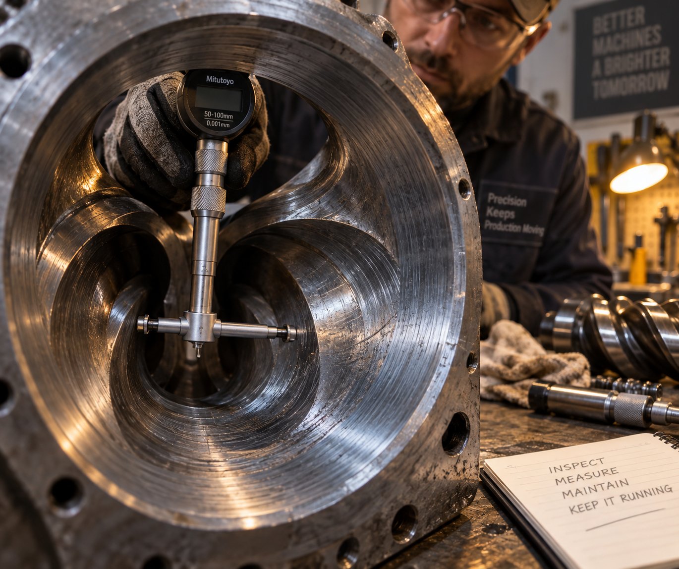
- Visible surface scoring on the screw flights or barrel bore — When the extruder is pulled for inspection, grooves, galling marks, or uneven hard-facing wear on the flight tips confirm that metal-to-metal contact has occurred. Industry experts note that a screw should never be refurbished more than three times, because repeated welding of new hard facing onto the base metal degrades the substrate and increases the risk of delamination during production.
So when should you replace rather than repair? The decision framework depends on application criticality and wear severity. A common industry guideline flags replacement when flight clearance reaches four times the original specification — for example, a conical screw set that started with 0.10 mm clearance per side would be evaluated for replacement at 0.40 mm. However, for precision applications like pressure-rated pipe, tighter thresholds of two to three times the original clearance are more appropriate, since even moderate back-leakage introduces wall-thickness variation that pressure testing will catch.
Re-nitriding a worn screw restores surface hardness but does not recover lost dimensional material. If the flight OD has reduced beyond the point where re-nitriding can restore effective clearance, full replacement is the only reliable path. Likewise, barrel bore wear should be measured at the feed, compression, and metering zones each time the screw is pulled — bimetallic barrel liners typically last about three times the service life of a screw, but abrasive formulations and misalignment can shorten that considerably.
Sourcing precision-manufactured replacement conical twin screw barrels from specialists like NANHAIYA ensures that the new barrel's taper, bore finish, and metallurgical properties match OEM specifications — critical for stable plasticizing and minimal production interruption. NANHAIYA serves PVC pipe, profile, board, foam board, and WPC extrusion manufacturers with barrels engineered for dimensional accuracy and corrosion resistance, so the replacement integrates with existing screw sets without recalibration delays.
Keeping a spare screw set in inventory is another best practice that pays dividends. When the active set reaches end-of-life, the spare can be installed during a scheduled changeover rather than forcing an emergency shutdown that halts production for days while replacement parts are ordered and shipped.
Beyond the Screw and Barrel: Other Critical Maintenance Areas
PVC extrusion line maintenance best practices extend well beyond the plasticizing unit. Several other components require regular, scheduled attention to prevent quality drift and unexpected stops:
- Die cleaning — Carbon buildup and degraded PVC residue accumulate on die land surfaces, flow channels, and mandrel tips over extended production runs. This buildup restricts flow, creates streaks and dimensional variation, and can introduce black specks into the product. Cleaning the die during material changes or at regular intervals — and inspecting seal surfaces and bolt torque each time the die is reassembled — prevents these defects from reaching the calibration tank.
- Temperature controller calibration — PID controllers that regulate barrel zone and die temperatures can drift over time. A thermocouple reading that is off by just 3 °C–5 °C may not trigger an alarm but is enough to shift plasticization quality, especially in the sensitive compression and metering zones where PVC is closest to its degradation threshold. Periodic verification against a calibrated reference thermocouple keeps the process centered.
- Gearbox lubrication — The reduction gearbox transmits enormous torque at low speed, and its internal gear surfaces depend on clean, thermally stable lubricant to prevent scoring and overheating. Synthetic gear oil is the standard choice for extrusion drive gearboxes. Monitor oil color, level, and temperature under load weekly; replace the oil at the intervals specified by the gearbox manufacturer — typically every 3,000 to 5,000 operating hours, or sooner if the oil darkens, foams, or shows metallic particles.
- Vacuum pump maintenance — The vacuum calibration tank relies on consistent vacuum pressure to hold pipe diameter. Rotary vane vacuum pumps require regular oil changes, vane inspection, and filter replacement. A declining ultimate vacuum reading — measured monthly against the pump's baseline — signals vane wear, oil contamination, or seal degradation that will eventually cause dimensional drift in the finished pipe.
- Haul-off pads and belts — Worn or hardened caterpillar pads lose grip, causing micro-slippage that introduces periodic wall-thickness variation. Weekly inspection of belt condition and encoder feedback accuracy catches this before it becomes a quality issue.
Preventive Maintenance Schedule Overview
Organizing all of these tasks into a single, accessible reference makes compliance practical. The table below maps the most critical components to their recommended inspection intervals, the specific maintenance action required, and the real-world consequence of neglect. Post this schedule on the production floor — when every operator and maintenance technician can see it, the gap between "knowing" and "doing" closes fast.
| Component | Inspection Interval | Maintenance Action | Consequence of Neglect |
|---|---|---|---|
| Screw and barrel clearance | Monthly measurement; trend quarterly | Measure flight OD and barrel bore at feed, compression, and metering zones. Compare to original specs. Re-nitride or replace when clearance exceeds 2-4x original tolerance. | Declining output, rising motor current, rough pipe surfaces, wall-thickness drift, and eventual unplanned shutdown |
| Die and adapter | Every material change or every 500 production hours | Disassemble, clean carbon and degraded residue from flow channels, inspect seal surfaces, re-torque bolts on reassembly | Streaks, black specks, dimensional variation, flow imbalance, and potential melt leakage |
| Temperature controllers and thermocouples | Quarterly calibration check | Verify each zone reading against a calibrated reference thermocouple. Replace drifted or sluggish sensors. | Inconsistent plasticization, localized overheating, yellowing, and degradation risk |
| Gearbox oil | Weekly level and color check; replace every 3,000-5,000 hours | Monitor oil level, color, and temperature under load. Replace synthetic gear oil per manufacturer schedule. Investigate metallic particles immediately. | Gear surface scoring, overheating, bearing failure, and catastrophic gearbox damage |
| Vacuum pump | Monthly performance test; oil per manufacturer interval | Measure ultimate vacuum against baseline. Change oil, inspect vanes, clean or replace filters. | Vacuum instability, OD variation, out-of-round pipe, and increased pump energy consumption |
| Haul-off pads and belts | Weekly visual and grip check | Inspect for wear, hardening, or uneven surfaces. Verify encoder speed feedback matches actual pipe speed. | Micro-slippage, wall-thickness oscillation, surface marking on pipe, and cut-length inaccuracy |
| Cutter blade | Weekly inspection; sharpen or replace as needed | Check blade edge, clamp alignment, and cut-timing accuracy across 10+ consecutive cuts. | Burrs, angled cuts, increased cutting force, and mechanical stress on cutter assembly |
| Electrical cabinet | Weekly filter and fan check; monthly terminal inspection | Clean VFD heat sinks and cabinet air filters. Tighten terminal connections. Verify grounding integrity. | VFD overtemperature trips, intermittent faults, control instability, and potential safety hazards |
| Cooling water system | Weekly water temperature and flow check; monthly filter cleaning | Clean strainers and spray nozzles. Monitor water temperature, pH, and hardness. Descale heat exchangers as needed. | Reduced cooling capacity, dimensional drift, warping, and fouling that mimics process faults |
Trend data is the difference between planned maintenance and emergency repair. If motor current, screw clearance, or vacuum performance moves in the wrong direction for two or three consecutive readings, schedule the correction before the line forces the schedule for you.
A disciplined maintenance program keeps every station on the line running within its designed parameters — but even the best-maintained line will occasionally produce a pipe that does not look or measure the way it should. When defects do appear, knowing how to trace them back to their root cause quickly separates a brief adjustment from a prolonged, frustrating troubleshooting session.
Troubleshooting Common PVC Pipe Defects
A pipe that comes off the line looking wrong is not a mystery — it is a message. Every surface blemish, dimensional drift, and discoloration points back to a specific imbalance somewhere in the extrusion process. The challenge is reading that message accurately and fast enough to minimize scrap. Surprisingly, most PVC pipe making machine guides stop at maintenance checklists and never address what happens when a defect actually shows up on the production floor. What follows is a practical, defect-by-defect troubleshooting reference designed to sit next to the control panel — not gather dust in a binder.
Surface and Dimensional Defects
These are the defects you can see and measure immediately, and they account for the majority of rejection events on a typical PVC pipe production line.
Rough inner surface is one of the most frequently encountered issues, and its root cause almost always traces back to inadequate plasticization. When the PVC compound is not fully gelled by the time it reaches the die, partially fused particles create a textured, matte-like finish on the pipe's bore. The usual culprits? Barrel temperatures set too low in the compression and metering zones, screw speed that is too high relative to the thermal profile (the material passes through too quickly to absorb enough heat), or a worn or damaged mandrel surface that physically imprints defects onto the inner wall. Sometimes the formulation itself is the issue — an incorrect lubricant balance can prevent the melt from flowing smoothly over tooling surfaces.
Wall-thickness variation is the defect that pressure-testing catches mercilessly. When you measure around the pipe circumference and find one side consistently thicker than the other, the first place to look is the die head. Misalignment between die and mandrel — even by fractions of a millimeter — shifts material distribution to one side. If the variation appears as a repeating thick-thin pattern along the pipe length rather than around the circumference, the haul-off unit becomes the prime suspect. Speed oscillations from worn caterpillar pads, unstable clamping pressure, or drive inconsistencies create a rhythmic stretching and relaxing of the pipe wall that shows up as periodic thickness fluctuation.
Out-of-round pipe (ovality) is a dimensional defect that makes joint assembly difficult or impossible. Imagine the soft tube exiting the die — it is perfectly round at that moment, but several downstream forces can distort it before it solidifies. Insufficient vacuum pressure in the calibration tank fails to hold the pipe firmly against the sizing sleeve, allowing gravity or uneven cooling to pull it out of round. A worn calibration sleeve with an elliptical bore will stamp that shape onto every meter of pipe. Uneven spray patterns — caused by clogged nozzles delivering more water to one side — cool the pipe asymmetrically, and the side that solidifies first shrinks and pulls the cross-section into an oval. Haul-off misalignment with the extruder centerline can exert a lateral force that deforms the still-pliable pipe as well.
Material Degradation and Internal Defects
These defects originate inside the material itself, often before the melt even exits the die. They are harder to spot visually but carry serious performance consequences.
Yellowing or burn marks signal that PVC has begun to thermally degrade — a chemical breakdown where the polymer releases hydrogen chloride gas, leaving behind a discolored, weakened structure. The fix direction depends on which part of the heat history is excessive. Are barrel zone temperatures too high? Is the residence time too long — perhaps because of a die with an overly long flow path, or because the line is running at reduced speed while temperatures remain at full-production setpoints? Frequent hot start/stop cycles are another common trigger that operators overlook; each time the screw stops and restarts, the stagnant melt in the barrel absorbs additional heat without moving forward. Weak stabilizer synergy in the formulation can also lower the compound's resistance to thermal exposure, making degradation appear even at temperatures that previously seemed safe.
Bubbles and voids trapped inside the pipe wall compromise structural integrity in ways that are invisible from the outside. Moisture is the most frequent cause — even a small amount of water in the PVC dry blend vaporizes under barrel temperatures, creating steam pockets that become frozen into the pipe wall during cooling. Excessive processing temperatures can also decompose PVC, releasing gas that becomes entrapped. If the extruder's vacuum venting system is malfunctioning or the vent port is partially blocked, volatiles that should escape are instead carried into the die and sealed into the product. The fix starts with confirming raw-material moisture levels, then verifying that the vent zone operates under adequate vacuum, and finally reviewing the temperature profile for hot spots.
Surface pitting — small, irregular craters scattered across the pipe exterior — points to contamination or degraded material in the melt stream. Foreign particles, carbonized PVC residue from dead zones inside the die or adapter, and degraded regrind material all create localized imperfections as they pass through the die land and calibration sleeve. Improving filtration, tightening regrind quality control, and maintaining a rigorous die-cleaning schedule address the most common sources.
Brittleness and cracking during cutting or handling often indicate a formulation problem rather than a pure machine issue — insufficient impact modifier, excessive filler loading, or over-shearing that damages the polymer chains. However, rapid or uneven cooling can introduce internal stresses that make otherwise adequate formulations behave as if they are brittle. Slowing the cooling rate and verifying additive dosing are the first diagnostic steps.
The complete troubleshooting reference below consolidates every major PVC pipe extrusion defect into a single scannable table. Print it, laminate it, and keep it at the operator station — because the fastest path from defect to correction is a structured diagnostic, not guesswork.
| Defect | Probable Cause(s) | Recommended Adjustment |
|---|---|---|
| Rough inner surface | Barrel temperatures too low (inadequate plasticization); screw speed too high relative to thermal profile; damaged or fouled mandrel surface; lubricant imbalance in formulation | Increase barrel temperatures in compression and metering zones gradually; reduce screw speed to extend melt residence time; clean and polish the mandrel; review formulation lubrication package |
| Rough outer surface | Low melt temperature causing incomplete gelation; moisture in raw material; worn or scratched die land; contaminated calibration sleeve | Raise die and final barrel zone temperatures; verify dry-blend moisture level and mixer operation; inspect and polish die surfaces; clean or replace calibration sleeve |
| Wall-thickness variation (circumferential) | Die-to-mandrel misalignment (eccentricity); uneven die-head temperature zones; material buildup causing flow obstruction | Re-center mandrel using die adjustment bolts while monitoring output; verify all die-head heater bands are functioning; clean flow channels and remove degraded residue |
| Wall-thickness variation (longitudinal) | Haul-off speed instability; fluctuating extruder melt pressure; inconsistent raw-material feeding; worn haul-off pads causing micro-slippage | Check haul-off drive and encoder feedback for speed oscillation; stabilize feeder output; replace worn caterpillar pads; verify VFD tuning and PID response |
| Out-of-round pipe (ovality) | Insufficient vacuum in calibration tank; worn or elliptical calibration sleeve; uneven cooling spray pattern; haul-off misalignment with line centerline; pipe sagging between support rollers | Verify vacuum pump performance and seal integrity; replace worn sizing sleeve; clean and unclog all spray nozzles for uniform water distribution; realign haul-off to extruder centerline; add or adjust roller supports |
| Yellowing or burn marks | Excessive barrel or die temperatures; prolonged residence time (low line speed at full temperature); frequent hot start/stop cycles; insufficient thermal stabilizer in formulation; dead zones in adapter or die | Reduce barrel zone temperatures incrementally; increase line speed or lower temperatures during reduced-output runs; minimize unplanned stops; review stabilizer dosage and synergy; clean die and adapter to eliminate stagnation points |
| Bubbles or voids | Moisture in PVC dry blend; blocked or insufficient vacuum venting on extruder; excessive melt temperature causing PVC decomposition; air entrapment from hopper feed irregularities | Verify raw-material moisture content and mixer cooling stage; clean vent port and confirm vacuum level; reduce melt temperature in degradation-prone zones; ensure consistent hopper feeding without air pockets |
| Surface pitting | Contaminated raw material or degraded regrind; carbonized deposits breaking free from die dead zones; inadequate melt filtration | Tighten incoming material inspection and regrind quality control; perform thorough die cleaning; install or maintain screen pack or melt filter; reduce regrind percentage temporarily to isolate cause |
| Black specks or streaks | Carbonized PVC residue from overheated dead zones; contaminated feedstock; degraded material on die or adapter surfaces | Disassemble and deep-clean die, adapter, and screen pack; inspect barrel for hot spots and repair heater bands; eliminate contamination sources in material handling |
| Brittleness or cracking | Insufficient impact modifier; excessive filler content; over-shearing during extrusion (screw speed too high); rapid or uneven cooling introducing internal stress | Review and adjust formulation additive ratios; reduce screw speed; extend cooling tank length or slow line speed for more gradual solidification; verify cooling water temperature uniformity |
Every PVC pipe defect has a machine-related or formulation-related root cause — never accept "bad batch of material" as a final answer without verifying process parameters first.
Effective troubleshooting cuts scrap rates and protects margins, but it is inherently reactive — it addresses problems after they appear. The most impactful decisions happen earlier, long before the first kilogram of PVC enters the hopper: selecting the right production line for your target pipe range, calculating the capacity you actually need, and evaluating whether a supplier can support you beyond the invoice date.
How to Choose the Right PVC Pipe Production Line
Knowing how every component works, what defects look like, and how maintenance prevents downtime is valuable — but none of it matters if you buy the wrong line in the first place. This is where everything covered in this article converges into a single, high-stakes decision: matching a PVC pipe making machine to your specific business requirements. Get it right, and you have a production asset that generates profit for a decade or more. Get it wrong, and you are stuck with equipment that either cannot meet demand or sits partially idle while you pay off the financing.
The process is more methodical than most buyers expect. It starts not with machine catalogs, but with the pipe you intend to sell.
How to Calculate Required Production Capacity
Before comparing extruder models or requesting quotes, work backward from your market. How to choose a PVC pipe making machine begins with four concrete data points:
- Target pipe diameter range and wall thickness — Are you producing 20–63 mm conduit, 110–250 mm drainage pipe, or 315–630 mm pressure mains? Each range requires a fundamentally different machine configuration, as the technical specifications section of this article illustrated. Wall thickness — driven by SDR and PN class — determines how much raw material each meter of pipe consumes.
- Daily output targets and shift schedule — A factory running two 8-hour shifts per day has only two-thirds the production hours of a three-shift operation. Your required daily tonnage divided by your available operating hours gives the minimum kg/h your extruder must sustain.
- Raw-material type — Virgin PVC dry blend, recycled PVC pellets, or a blend of both? Recycled content above 20–30% typically reduces line speed, increases the risk of contamination-related defects, and may require a screw geometry optimized for reprocessed feedstock. This affects both extruder selection and downstream quality expectations.
- Budget constraints — Not just the purchase price, but the total cost of ownership: energy consumption per kilogram, spare parts frequency, and the labor required to operate and maintain the line.
Here is how PVC pipe machine capacity calculation works in practice. Imagine you need to produce 110 mm OD UPVC pressure pipe at SDR 21 (PN 10), with a wall thickness of approximately 4.2 mm. Your target is 10,000 meters of finished pipe per day, and you plan to run two shifts of 10 hours each — 20 operating hours daily.
First, calculate the pipe's mass per meter. The cross-sectional area of the pipe wall is found using the standard annular formula:
Wall area = π/4 × (OD² − ID²)
For a 110 mm OD pipe with a 4.2 mm wall, the inner diameter is 101.6 mm. The wall cross-section works out to roughly 13.96 cm². Multiply by PVC density — approximately 1.40 g/cm³ for a typical rigid UPVC compound — and you get about 1.95 kg per meter of pipe.
Then, determine the required throughput:
10,000 meters ÷ 20 hours = 500 meters/hour
500 m/h × 1.95 kg/m ≈ 975 kg/h
That 975 kg/h figure is your minimum sustained extruder output. In reality, you should add a 10–15% margin to account for startup scrap, die changes, and brief unplanned stops — bringing the target to roughly 1,070–1,120 kg/h. Referring back to the specifications table earlier in this article, that output range points toward a conical twin-screw extruder in the 80/156 mm to 92/188 mm class with a main motor in the 200–315 kW range.
Notice how the calculation drives the machine selection — not the other way around. As industry sources emphasize, output should be evaluated together with pipe size, wall thickness, and actual production requirements rather than relying solely on the maximum theoretical capacity shown in a specification sheet. A machine rated at 1,200 kg/h on a datasheet may only sustain 900 kg/h on your specific formulation and pipe size — and that gap can derail your entire production plan.
For manufacturers targeting smaller-diameter pipes — say 20–32 mm electrical conduit — the math shifts in a different direction. Individual pipe mass per meter is low, so the bottleneck becomes line speed rather than extruder tonnage. This is exactly where multi-cavity configurations become relevant: a 2-output or 4-output line produces multiple pipes simultaneously from a single extruder, dramatically improving productivity without doubling equipment cost. A 4-output configuration for 16–32 mm conduit can deliver 220–450 kg/h depending on extruder size, effectively multiplying your meters-per-hour output by four compared to a single-cavity setup.
Installation, Commissioning, and Supplier Evaluation
Purchasing the line is only the midpoint of the project. What happens between delivery and stable production is where many new manufacturers encounter unexpected delays and costs. PVC pipe extrusion line installation requirements extend well beyond plugging in the equipment.
Site preparation demands careful planning. A complete production line — extruder, calibration tank, cooling baths, haul-off, cutter, and stacker — can stretch 25 to 40 meters in length depending on pipe size, with additional floor space needed for raw-material storage, mixing equipment, and finished-pipe staging. The floor must be level and strong enough to support the extruder and gearbox assembly, which can weigh several tons. Ceiling height matters too: overhead cranes or hoists are essential for die changes and screw removal during maintenance.
Utility requirements are equally specific:
- Electrical supply — Three-phase power at the correct voltage and frequency for your region (typically 380V/50Hz or 415V/50Hz, though 440V/60Hz is common in parts of the Americas). The total connected load for a mid-range line can reach 200–400 kW, so confirm that your facility's transformer and switchgear can handle the demand without voltage drops that destabilize the VFDs.
- Cooling water — The calibration and cooling tanks consume significant water volumes. A recirculating chilled-water system with adequate capacity — often requiring a cooling tower or chiller unit — is essential. Water temperature, flow rate, and available plant utilities should be specified during the quotation stage, not discovered during installation.
- Compressed air — Required for pneumatic actuators on the cutter, belling machine clamps, and various control valves throughout the line. A dedicated compressor with a dryer and filter system is standard.
Operator training is the factor that separates a smooth commissioning from a frustrating one. PVC extrusion is not intuitive — the interaction between screw speed, barrel temperatures, vacuum pressure, and haul-off speed requires hands-on experience to manage confidently. Reputable suppliers include on-site commissioning support and operator training as part of the purchase agreement, typically spanning one to three weeks depending on line complexity. During this period, technicians run the line through its full operating range, document the process parameters for each pipe size, and train your operators on startup, shutdown, changeover, and basic troubleshooting procedures.
What is a realistic timeline from equipment delivery to stable, sellable production? For a straightforward single-output line with experienced installation crews, expect four to eight weeks for mechanical and electrical installation, followed by one to three weeks of commissioning and trial production. Multi-output lines, large-diameter systems, or facilities built from scratch may extend this timeline to three months or more.
Finally — and this is the piece most PVC pipe production line buying guides underemphasize — evaluate the supplier beyond the initial sale. The machine will run for years; the relationship with the supplier needs to last just as long. Industry best practice recommends confirming several post-purchase capabilities before signing any contract:
- Spare parts availability — Particularly for high-wear components like screws, barrels, die tooling, calibration sleeves, and haul-off pads. Ask the supplier which parts require periodic replacement and what lead times look like. A supplier who can deliver a replacement conical twin-screw barrel within days rather than months is worth the premium.
- Technical support responsiveness — Can the supplier provide remote troubleshooting via video call? Do they maintain a team of field service engineers who can travel to your site when remote guidance is not enough? Downtime costs money every hour, and a supplier who takes a week to return a technical inquiry is a supplier who will cost you production.
- Documentation and process recipes — Does the supplier provide detailed process parameter sheets for each pipe size the line is designed to produce? These recipes — screw speed, zone temperatures, vacuum setpoints, haul-off speed, cooling water temperature — are invaluable for operators and dramatically reduce the trial-and-error period when switching between products.
- Customization capability — Not every project fits a standard catalog configuration. Pipe specifications, required output, factory conditions, and automation requirements may demand changes to the standard production line. A supplier with genuine engineering capability can review these requirements and modify the machine design before finalizing — rather than delivering a standard unit and leaving you to adapt it yourself.
- Reference projects and production evidence — Ask for videos, testing records, or customer references from projects producing the same pipe material and diameter range you plan to manufacture. A supplier who has already solved your exact production challenge carries far less risk than one quoting from a generic spec sheet.
- Factory acceptance testing — Whenever possible, witness a production trial at the supplier's facility before shipment. Define the test material, pipe size, wall thickness, run duration, and acceptance criteria in advance so that both parties agree on what constitutes a successful test. Record the operating parameters during the trial — these become your baseline for replicating results at your own plant.
The best PVC pipe production line is not the one with the highest rated output or the lowest purchase price — it is the one that consistently produces the pipe quality your market demands at a competitive operating cost, backed by a supplier who remains engaged long after delivery.
Selecting a production line is ultimately an exercise in alignment. Your target pipe type defines the formulation and processing temperature range. The formulation dictates the extruder architecture, screw metallurgy, and die design. The pipe diameter and wall thickness determine the required throughput, cooling length, and haul-off capacity. Daily output goals set the minimum kg/h your extruder must sustain. And the supplier you choose determines whether the gap between rated performance and real-world results stays narrow — or widens with every passing month. Each of these variables connects back to the fundamentals covered throughout this article: the process stages, the component engineering, the maintenance discipline, and the troubleshooting knowledge that together define whether a PVC pipe making machine becomes a reliable profit center or an ongoing source of frustration. Approach the decision with the same rigor you would apply to the pipe standards your product must meet, and the line will repay that investment for years to come.
Frequently Asked Questions About PVC Pipe Making Machines
1. What components make up a complete PVC pipe making machine?
A PVC pipe making machine is not a single device but an integrated production line. It consists of a conical twin-screw extruder for melting and homogenizing PVC dry blend, a die head that shapes the melt into a tubular profile, a vacuum calibration tank that locks the outer diameter to precise tolerances, spray and immersion cooling tanks, a caterpillar or belt-type haul-off unit that controls line speed and wall thickness, a planetary saw or chip-free cutter for length cutting, and a belling machine with automatic stacker for finished pipe handling. Each unit must be precisely synchronized — adjusting one parameter without rebalancing the others leads to wall-thickness drift, surface defects, or dimensional failures.
2. Why is a conical twin-screw extruder preferred over a single-screw extruder for rigid PVC pipe?
Rigid PVC is one of the most thermally sensitive commercial polymers, and the conical twin-screw architecture was purpose-built for this challenge. Its two counter-rotating screws taper from a large feed diameter to a smaller discharge diameter, creating high torque at low rotational speeds (typically 30-150 RPM). This converging geometry accepts bulky PVC powder efficiently at the inlet and naturally builds the high discharge pressure pipe dies require — without generating the excessive shear heat that degrades PVC. Single-screw extruders rely on barrel-wall friction to convey material, which works poorly with dry PVC powder, resulting in uneven feeding and a narrower processing window. Manufacturers needing custom or replacement conical twin screw barrels can source precision-engineered components from specialists like NANHAIYA to maintain stable plasticization across PVC pipe, profile, board, and WPC lines.
3. How do you calculate the required output capacity for a PVC pipe production line?
Start by identifying your target pipe OD and wall thickness, then calculate the pipe wall cross-sectional area using the annular formula: Wall area = pi/4 x (OD squared minus ID squared). Multiply that area by PVC density (approximately 1.40 g/cm3 for rigid UPVC) to get mass per meter. Next, divide your daily meter target by available operating hours to find meters per hour, then multiply by kg per meter to get the minimum sustained extruder output in kg/h. Add a 10-15% margin for startup scrap, die changes, and brief stops. For example, producing 10,000 meters per day of 110 mm PN 10 pipe over 20 operating hours requires roughly 975 kg/h, pointing to a conical twin-screw extruder in the 80/156 mm to 92/188 mm class.
4. What are the most common PVC pipe extrusion defects and how do you fix them?
Common defects include rough inner surfaces caused by inadequate plasticization (fix by raising barrel temperatures and reducing screw speed), circumferential wall-thickness variation from die-to-mandrel misalignment (re-center the mandrel using adjustment bolts), longitudinal wall-thickness fluctuation from haul-off speed instability (replace worn pads and verify VFD tuning), yellowing from thermal degradation (lower barrel temperatures and minimize hot start/stop cycles), bubbles from moisture in raw material (verify dry-blend moisture levels and vacuum vent function), and out-of-round pipe from insufficient vacuum calibration pressure or worn sizing sleeves. Each defect traces to a specific process imbalance, making structured diagnostics far more effective than guesswork.
5. How often should screw and barrel components be inspected on a PVC pipe extruder?
Screw and barrel clearance should be measured monthly and trended quarterly. Key wear indicators include increasing motor current at constant screw speed, declining output at the same RPM, and visible surface scoring on the screw flights. Industry guidelines recommend evaluating replacement when flight clearance reaches two to four times the original specification — with the lower threshold applying to pressure-rated pipe production where dimensional precision is critical. Re-nitriding restores surface hardness but cannot recover lost dimensional material, so full replacement is necessary when flight OD has reduced beyond the effective clearance range. Keeping a spare screw set in inventory and sourcing precision-manufactured replacement barrels from specialists ensures minimal production interruption during changeovers.
Written by
Nanhaiya Technical Team
Zhoushan Nanhaiya Plastic Machinery Co., Ltd.
The Nanhaiya technical team supports screw and barrel manufacturing projects through application review, technical communication, custom manufacturing coordination, and production and quality control.
Discuss Your Application
Related Articles
More insights on screw barrel technology and plastics processing.
What Your Film Extrusion Machine Datasheet Won't Tell You
Oct 20, 2026
Film extrusion machine guide covering blown vs cast processes, multilayer configurations, screw specs, resin selection, and supplier evaluation for production engineers.
Read Article
Raw Scrap to Perfect Pellets: Plastic Pelletizing Machine Guide
Oct 19, 2026
Learn how a plastic pelletizing machine converts scrap into uniform pellets. Covers cutting methods, extruder types, quality control, costs, and maintenance.
Read Article
Pet Sheet Extrusion Machine Secrets Your Supplier Won't Share
Oct 15, 2026
Learn how a PET sheet extrusion machine works, key components, specs by production scale, troubleshooting defects, and buyer tips your supplier won't share.
Read ArticleLooking for something else?
Search by material, symptom or product and jump straight to the relevant page.
These are navigation suggestions based on keyword matching — not a quotation, not a delivery commitment, and not a substitute for engineering review. Final specification is confirmed by our engineers against your drawings and processed material.
Need help with screw barrel selection?
Share your machine model, processed material and application. Our team can help with pricing and technical support.