

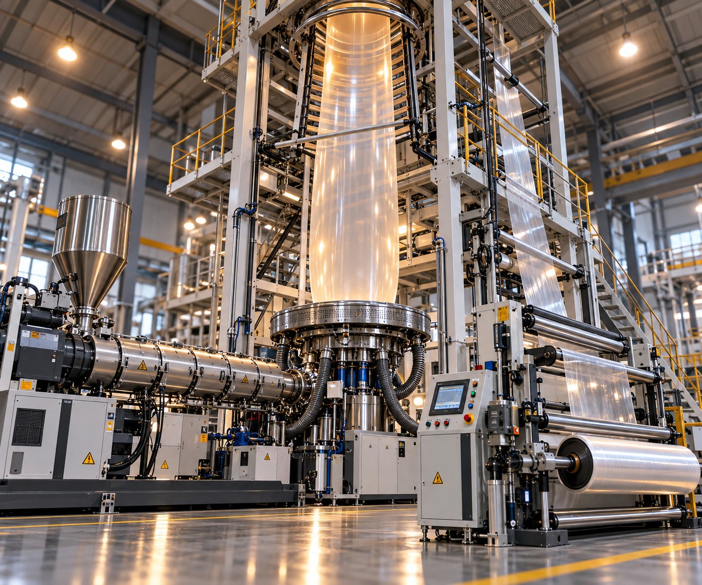
What Is a Film Extrusion Machine and Why It Matters
Imagine unwrapping a snack bar, stretching cling wrap over leftovers, or walking past a greenhouse shimmering with translucent plastic sheeting. Every one of those thin polymer layers started life inside a film extrusion machine. Yet most buyers and engineers encounter datasheets packed with numbers — screw diameters, output rates, die widths — without ever getting the practical context behind them.
This guide changes that. It covers blown film, cast film, monolayer, and multilayer configurations in a single resource, giving plant managers, production engineers, and procurement professionals the real-world knowledge that spec sheets leave out.
What Is a Film Extrusion Machine
A film extrusion machine is an integrated manufacturing system that melts polymer resin pellets and continuously forms them into thin, flexible film — either by inflating molten plastic through a circular die (blown film extrusion) or by spreading it across a flat die onto chilled rolls (cast film extrusion).
At its core, every unit performs three jobs: it melts raw resin, shapes that melt into a uniform web, and cools the web so it can be wound into finished rolls. The differences between machine types — die geometry, cooling method, orientation direction — determine the mechanical and optical properties of the final film. Plastic film extrusion is, in that sense, less about the hardware alone and more about how hardware choices translate into product performance.
Why Film Extrusion Matters Across Industries
The global plastic film market is expected to reach USD 84.67 billion by 2031, growing at a 3.18% CAGR. That figure reflects just how deeply extruded films are embedded in daily commerce and infrastructure. Consider the range of sectors that depend on them:
- Food packaging — barrier pouches, snack wrappers, frozen-food bags, and meat-and-cheese vacuum films that extend shelf life.
- Logistics and e-commerce — stretch wrap, shrink bundling, courier bags, and pallet hoods that protect goods in transit.
- Agriculture — greenhouse covers, mulch films, silage wrap, and NIR-blocking sheets used in controlled-environment farming.
- Healthcare and pharmaceuticals — sterile barrier films, IV-bag layers, blister packaging, and breathable PE surgical drapes.
- Construction and industrial — vapor barriers, geomembranes, protective surface films, and anti-static wraps for electronics.
Each of these applications demands a specific combination of clarity, strength, barrier performance, and cost efficiency — and the type of plastic film extrusion line behind the product is what makes or breaks those targets. A stretch wrap producer needs the speed and optical clarity of a cast line, while a heavy-duty bag manufacturer relies on the balanced tear strength only a blown process delivers.
Understanding the machine that produces your film is not optional knowledge — it is the foundation of every quality, cost, and throughput decision you will make. The sections ahead break down each technology, configuration, and parameter so you can read a datasheet and know exactly what it means for your production floor.
Blown Film vs Cast Film Extrusion Compared
Every film extrusion machine falls into one of two fundamental camps — and picking the wrong one can cost you months of production headaches. Blown film lines and cast film lines both start with the same raw material: molten polymer. Yet the way each system shapes and cools that melt produces films with dramatically different properties. Think of it like baking bread versus making flatbread — same dough, different processes, entirely different results.
If you have ever wondered why your stretch wrap is crystal-clear while your grocery bag feels tougher but looks hazier, the answer lives right here.
How Blown Film Extrusion Differs from Cast Film Extrusion
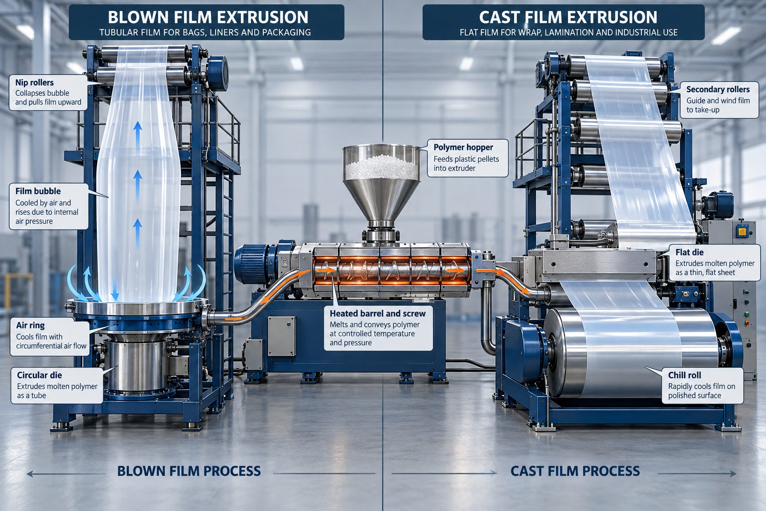
In blown film extrusion, molten polymer is pushed through a circular (annular) die oriented vertically. Compressed air is injected into the center of the extruded tube, inflating it into a large bubble — much like blowing up a balloon. As the bubble rises, it stretches the film simultaneously in both the machine direction (lengthwise) and the transverse direction (widthwise). An external air ring cools the bubble from the outside. At the top of the tower, collapsing frames and nip rollers flatten the bubble into a double-layered sheet, which is then wound into rolls.
This biaxial stretching is the defining feature. Because the film orients in two directions at once, blown film develops balanced tear strength, puncture resistance, and toughness across the entire web.
In cast film extrusion, the molten polymer exits through a flat die — often a coat-hanger or T-slot design — and lands directly onto a highly polished, water-cooled chill roll. The rapid quenching solidifies the film almost instantly, preventing large polymer crystals from forming. The result is a film with exceptional optical clarity, high gloss, and very tight thickness tolerances. From there, the film passes through additional rollers for edge trimming and tension control before winding.
The trade-off? A film casting system stretches material primarily in the machine direction (uniaxial orientation). That gives cast film superior clarity and gauge uniformity, but it also makes the film more prone to tearing along the machine direction and generally less puncture-resistant than blown film.
Film Properties and Application Fit
Choosing between blown and cast film products is never about which process is "better" — it is about which properties your end product demands. Here is a practical breakdown:
- Optical clarity and gloss — Cast film wins decisively. Rapid chill-roll cooling suppresses crystallization, producing a transparent, glossy surface ideal for retail display wrapping and clear overwrap where visual appeal matters.
- Mechanical strength and puncture resistance — Blown film takes the lead. Biaxial orientation distributes stress evenly, making it the go-to for heavy-duty sacks, frozen-food bags, and agricultural films that face rough handling.
- Thickness uniformity — Cast extrusion typically achieves tolerances of plus or minus 1-2%, compared to plus or minus 3-5% on standard blown film lines. For applications like medical barrier films where consistent gauge means consistent protection, this difference is significant.
- Barrier performance — Blown film's biaxial orientation and slower cooling can enhance barrier properties in certain polymers, making it a strong candidate for high-barrier co-extrusions with strict OTR or MVTR requirements.
- Flexibility and down-gauging — Blown film can be made thinner while retaining its strength, offering potential material savings without compromising performance.
The table below puts these differences side by side so you can quickly match each method to your production priorities:
| Criteria | Blown Film Extrusion | Cast Film Extrusion |
|---|---|---|
| Process Mechanism | Annular die + air-inflated bubble | Flat die + water-cooled chill roll |
| Film Orientation | Biaxial (MD + TD) | Primarily uniaxial (MD) |
| Optical Clarity | Moderate — hazier due to slower cooling | Excellent — high gloss, low haze |
| Thickness Control | Good (approx. ±3-5%) | Superior (approx. ±1-2%) |
| Typical Applications | Grocery bags, shrink wrap, agricultural films, heavy-duty sacks, medical pouches | Stretch film, clear overwrap, CPP packaging, IV bags, lamination substrates |
| Line Speed | Typically 50-300 m/min | Up to 600 m/min |
| Capital Investment | Generally lower initial equipment cost | Higher equipment cost; faster ROI at high volumes |
When to Choose Each Method
Imagine you are specifying a line for stand-up pouches that will hold frozen vegetables. The bags face freezer burn, rough transit, and consumer abuse when dropped on a kitchen counter. You need balanced tear strength and puncture resistance — blown film extrusion is your match.
Picture a different scenario: your customer wants a crystal-clear bread bag that runs at maximum throughput on an automated form-fill-seal line. Optical clarity, tight gauge, and speed are non-negotiable. A cast film line delivers all three.
Here is a quick decision guide:
- Choose blown film when you need aggressive puncture resistance, balanced MD/TD strength, wide-width flexibility, or high-barrier co-extruded structures for demanding environments.
- Choose cast film when optical transparency, precise thickness control, high-speed output, or a smooth surface finish for printing and laminating are your top priorities.
- Consider both if your product portfolio spans blown and cast film products — many converters operate both line types to serve diverse customer requirements from a single facility.
Neither technology is obsolete or universally superior. The real skill lies in matching the process to the product — and that starts with understanding exactly how each system transforms a simple polymer pellet into finished film. The blown film process, in particular, involves a carefully orchestrated sequence of steps where small parameter changes create large quality swings.
How the Blown Film Extrusion Process Works Step by Step
A blown film machine can look deceptively simple from the outside — resin goes in at the bottom, a bubble rises in the middle, and finished rolls come off the winder. But between those two endpoints sits a tightly choreographed sequence of thermal, mechanical, and pneumatic events. Miss one beat, and you end up with gauge variation, hazy film, or a collapsed bubble that shuts down your line.
Understanding the blown film extrusion process stage by stage is what separates operators who react to problems from engineers who prevent them. Here is exactly how each stage works — and where it can go wrong.
- Resin feeding — Polymer pellets enter the extruder hopper, typically via a gravimetric or volumetric feeder.
- Plasticization — The single screw melts and homogenizes the resin across multiple heated barrel zones.
- Melt conveyance — The screw pushes the molten polymer forward under pressure toward the die.
- Extrusion through the annular die — The melt exits through a circular die gap, forming a thin-walled tube.
- Bubble inflation — Compressed air injected through the die center inflates the tube into a cylindrical bubble.
- Air ring cooling — External air flow from the air ring solidifies the melt at the frost line.
- Collapsing — Collapsing frames and guide plates flatten the bubble into a double-layered web.
- Nip roll haul-off — Nip rollers seal the bubble, control internal air pressure, and pull the film upward at a controlled speed.
- Winding — The flat film is slit (if needed), tension-controlled, and wound into finished rolls.
Sounds straightforward? Each of these nine steps contains variables that interact with every other step. Let's zoom into the three most critical phases.
From Resin Pellets to Molten Polymer
Everything starts inside the extruder barrel. A single screw rotates within a heated cylinder, dragging resin pellets forward through three functional zones: the feed zone (where solids enter), the compression zone (where friction and heater bands melt the pellets), and the metering zone (where the melt is homogenized and pressurized for delivery to the die).
Screw design matters enormously here. The compression ratio — the depth of the feed-zone channel relative to the metering-zone channel — must match the bulk density and melt behavior of the specific polymer being processed. Run HDPE on a screw designed for LDPE, and you will likely see pressure surges, incomplete melting, and unacceptable gel counts in the finished film.
Temperature zone management is equally critical. A typical blown film extruder machine divides its barrel into four to six independently controlled heating zones. If zone temperatures ramp too aggressively, the polymer can degrade; too gradually, and you get unmelted particles that show up as specks or gels on the film surface. Process experts note that temperature inconsistencies are among the most common root causes of melt-quality defects, directly affecting both bubble stability and film clarity downstream.
You'll also notice that feed consistency plays a quiet but powerful role. Inconsistent pellet flow — caused by bridging in the hopper or moisture in the resin — starves the screw intermittently, producing pressure fluctuations that translate into thickness variation in the final film. Gravimetric feeders and hopper dryers exist specifically to eliminate this issue before it ever reaches the screw.
Bubble Formation and the Blow-Up Ratio
Once the melt exits the annular die, the real magic of blow film extrusion begins. Compressed air inflates the molten tube into a stable cylindrical bubble, and the degree of inflation is described by one of the most important parameters in the entire process: the blow-up ratio.
The blow-up ratio (BUR) is the ratio of the final bubble diameter to the die diameter. A die with a 200 mm opening inflated to a 600 mm bubble, for example, has a BUR of 3:1. This single number determines the film's final lay-flat width, thickness, and the degree of transverse-direction orientation imparted to the polymer chains.
Why does this matter on the production floor? A higher blow up ratio stretches the film more in the transverse direction, improving TD tear strength and allowing thinner gauges without sacrificing toughness. But push the BUR too high and the bubble becomes unstable — it starts oscillating, breathing, or even tearing apart. Most PE films run comfortably between a BUR of 1.5:1 and 4:1, depending on the resin and the desired end-use properties.
Bubble instability is one of the most disruptive problems a film blowing machine operator can face. Common triggers include inconsistent internal air pressure, uneven die flow caused by a poorly adjusted die gap, drafts in the production hall, and non-uniform cooling from the air ring. When the bubble oscillates, gauge variation spikes and scrap rates climb fast.
Modern blown film lines combat instability with internal bubble cooling (IBC) systems that regulate air pressure inside the bubble in real time, automatic die lip adjustment via thermal bolts, and dual-lip air rings that provide more uniform cooling around the full circumference. These features are rarely highlighted on a basic datasheet, yet they are often the difference between a line that hums and one that constantly trips.
Cooling, Collapsing, and Winding
The frost line — the visible boundary where the molten bubble transitions from transparent melt to opaque solid — is your visual indicator that cooling is doing its job. Frost line height is controlled primarily by air ring velocity and IBC flow. A higher frost line gives the polymer more time to orient before solidifying, which can enhance film toughness but also increases bubble sway risk. A lower frost line locks the molecular structure in place faster, improving gauge consistency at the expense of some mechanical balance.
Above the frost line, the solidified bubble enters the collapsing frame — a set of angled guide panels or rollers that gradually flatten the tube into a double-layered web. Poor collapsing-frame geometry or misalignment introduces wrinkles and edge folds that persist all the way to the finished roll. Operators often underestimate this stage, but it is a frequent source of downstream waste, particularly on wider film lines where even a small angular misalignment magnifies across the web width.
The nip rollers sit at the top of the collapsing section. They serve a dual purpose: sealing the bubble so internal air pressure stays constant, and pulling the film upward at a controlled haul-off speed. The ratio of haul-off speed to extrusion speed (called the draw-down ratio, or DDR) governs machine-direction orientation and, combined with the BUR, defines the final film thickness. Uneven nip pressure across the web can cause one edge to stretch more than the other, a subtle defect that only becomes apparent when the converter tries to print or laminate the roll.
Finally, the film reaches the winder. Surface winders and center winders each have trade-offs. Surface winders handle a broader range of film types but can create slip issues with very tacky resins. Center winders provide better tension control for thin, stretchy films. Regardless of type, consistent winding tension is essential — too tight and the roll telescopes or blocks; too loose and wrinkles get wound in permanently.
Every stage described above feeds into the next. A screw that delivers inconsistent melt temperature creates gauge bands the air ring cannot correct. An improperly set blow up ratio forces the collapsing frame to handle a bubble diameter it was not optimized for. This cascading relationship is exactly why experienced engineers evaluate a blown film extruder machine as a complete system rather than a collection of isolated components — and why the configuration choices covered next make such a dramatic difference in what the line can actually produce.
Understanding Cast Film Extrusion Technology
Blown film gets most of the educational airtime, yet a significant share of global film production — including stretch wrap, CPP packaging, and lamination substrates — rolls off cast film extrusion lines. The flat-die process trades the blown bubble for a streamlined horizontal workflow that delivers speed, clarity, and dimensional precision that many high-volume converters simply cannot achieve any other way.
The Cast Film Extrusion Process Explained
Picture molten polymer flowing through a wide, flat opening instead of a circular one. That is the essential shift. In a cast film extrusion machine, resin pellets enter the extruder barrel and are melted, mixed, and pressurized by the screw — the same plasticization fundamentals as blown film. The difference begins at the die.
The melt is delivered through a coat-hanger or T-slot die designed to spread polymer evenly across the full working width. Die lip adjustment — either manual or automated — fine-tunes the gap to control initial film thickness. As the molten curtain exits the die, it drops onto a highly polished, internally water-cooled chill roll rotating at a controlled speed. This rapid quenching is what gives cast film its signature advantage: because the polymer solidifies almost instantly, crystallization is suppressed, producing a film with exceptional optical clarity, high gloss, and minimal haze.
An air knife or vacuum box presses the molten web firmly against the chill roll to eliminate trapped air and ensure uniform contact. From there, the film passes through secondary cooling rolls that further stabilize its temperature, followed by an inline thickness gauge — typically beta-gauge or infrared — that continuously maps the profile across the web. Edge trimmers remove the thicker bead that naturally forms at both margins. Finally, the finished film is wound under precise tension control onto cores, ready for shipment or downstream converting.
A well-configured cast film machine can produce films from less than 10 microns to roughly 200 microns in thickness, and line speeds on a modern stretch film machine routinely reach 400-600 m/min — roughly double the pace of a comparable blown line. That speed, combined with tight gauge tolerance on the order of plus or minus 1-2%, makes cast extrusion the preferred route for high-volume commodity films where optical quality and throughput drive profitability.
Advantages and Limitations of Cast Film Lines
No process is universally superior, and understanding the trade-offs is what separates a sound capital decision from an expensive misstep. Here is what a cast film extrusion line does well:
Key Advantages
- Superior optical clarity and gloss — Rapid chill-roll cooling minimizes crystallization, delivering films with low haze that are ideal for retail display packaging and clear lamination layers.
- Tight thickness uniformity — Automated die-lip profiling combined with inline gauging keeps variation to plus or minus 1-2%, critical for medical and food-contact films.
- High line speeds — Cast lines can exceed 600 m/min, enabling higher output per shift and faster return on capital for large-volume products like stretch wrap and CPP film.
- Excellent surface flatness — Direct chill-roll contact produces a smooth, wrinkle-free web that prints and laminates consistently without pre-treatment surprises.
- Efficient multilayer capability — A modern cast film extruder can incorporate feedblock co-extrusion to combine multiple polymers in a single pass, producing complex barrier structures at speed.
Key Limitations
- Uniaxial orientation — Because the film stretches primarily in the machine direction during take-up, transverse-direction tear strength and puncture resistance lag behind blown film. This limits suitability for heavy-duty bags and applications that face multidirectional stress.
- Higher die cost — Flat dies for wide-web production are precision-engineered components that carry a higher price tag than annular dies of comparable output width.
- Edge bead waste — The natural thickening at both film edges must be trimmed and recycled, adding a small but real material-handling overhead.
- Limited lay-flat width flexibility — Changing the final film width on a cast line often requires a different die, whereas a blown film line can adjust width by simply changing the blow-up ratio.
One development that is reshaping what cast — and blown — film lines can achieve is MDO (Machine Direction Orientation) technology. An MDO unit, installed downstream of the extrusion section, heats and stretches the film at controlled ratios, typically around 5:1, to realign polymer chains in the machine direction. The result is a thinner film with significantly improved stiffness, barrier properties, and optical performance. According to Plastics Technology, MDO film is increasingly enabling converters to produce all-PE monomaterial structures that can replace traditional multimaterial PE/PET laminates — a major step toward recyclable flexible packaging. Processors have successfully produced mdo film as thin as 15-18 microns while maintaining process stability, opening doors to meaningful material cost savings and sustainability gains.
Whether you are running stretch wrap at 500 m/min or producing a specialty CPP lamination substrate, the cast process gives you a distinct combination of speed, clarity, and dimensional control. The real complexity arrives when you start stacking multiple polymer layers — and the choice between monolayer, ABA, ABC, and five-layer-plus configurations can reshape both your capital budget and your product capabilities entirely.
Machine Configurations from Monolayer to Multilayer
So you know the difference between blown and cast processes, and you understand how each stage of extrusion shapes the final film. But here is a question most datasheets gloss over entirely: how many extruders does your line actually need? The answer depends on how many distinct polymer layers your end product demands — and that single decision cascades through die design, capital cost, operator skill requirements, and the markets you can realistically serve.
Think of it this way. A monolayer line is a solo instrument. A multilayer co-extrusion line is an orchestra — each extruder plays its own part, and the die is the conductor that brings every voice together into a single, unified film structure.
Monolayer Machines for Standard Applications
A monolayer blown film line or cast line uses a single extruder feeding a single-channel die. One resin goes in; one homogeneous layer of film comes out. The mechanical simplicity is the main appeal — fewer moving parts, lower maintenance overhead, and a learning curve gentle enough for smaller operations to manage with a lean crew.
Capital costs reflect that simplicity. Entry-level monolayer systems can start in the $200,000-$350,000 range, roughly 50-70% less than comparable multilayer setups. Energy consumption is lower too, with industry data showing single-layer machines typically drawing 15-20% less power per kilogram of output compared to multi-extruder alternatives.
Where do they fit best? Commodity products that do not require barrier properties or layered functionality:
- Retail shopping bags and general-purpose poly bags
- Basic industrial wrap and protective sheeting
- Agricultural ground covers with uniform UV-stabilizer distribution
- Simple construction vapor barriers
Monolayer films still account for a significant share of non-food flexible packaging because, for many applications, a single well-chosen resin is all you need. The limitation surfaces when your customer asks for oxygen barriers, mixed-resin structures, or the ability to bury a recycled-content core inside virgin skin layers. That is where co-extrusion enters the picture.
Multilayer and Co-Extrusion Configurations
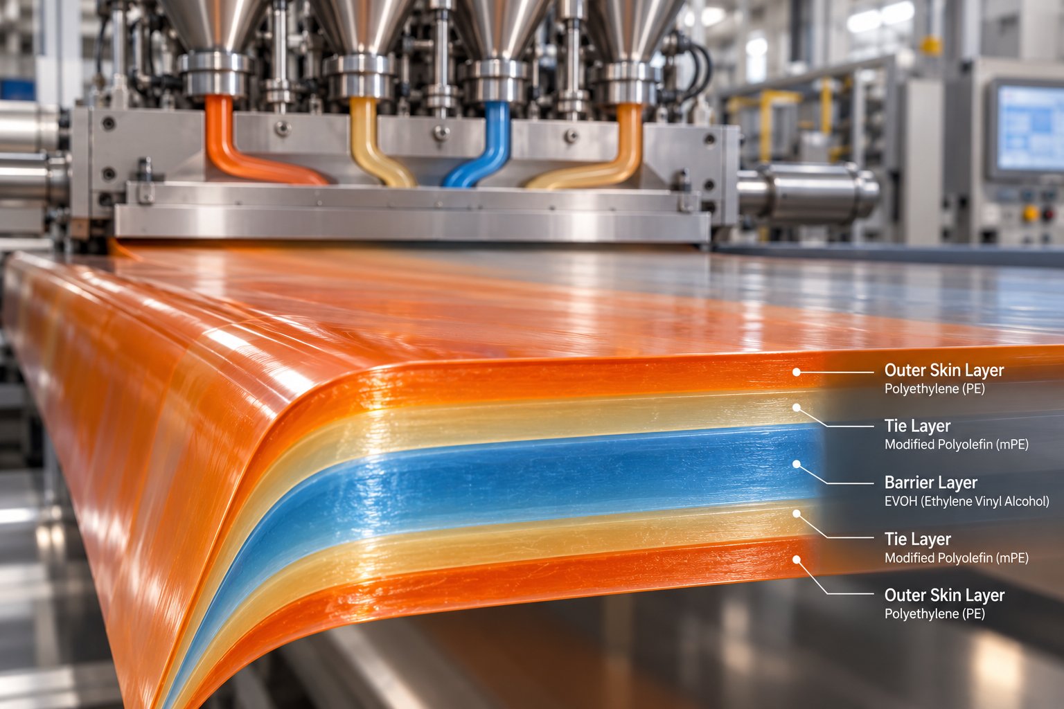
Imagine you need a film that seals easily on the inside, resists punctures on the outside, and blocks oxygen somewhere in between. No single polymer does all three. Co-extrusion solves this by running two or more extruders simultaneously, each melting a different resin, and combining those melt streams inside a single die before they exit as one unified multilayer web.
Two common entry-level structures illustrate the concept:
- ABA configuration — Two extruders feed three layers where the outer skins (A) are the same material and the core (B) is different. This symmetric structure is popular for incorporating recycled content or lower-cost resin in the center while keeping virgin material on the surfaces. A typical example: LLDPE skins over an LDPE or post-consumer recycled core for general-purpose bags.
- ABC configuration — Three extruders feed three distinct layers, each with a different polymer. This asymmetric design unlocks greater functional flexibility. You might combine an easy-seal inner layer, a stiff structural core, and a printable outer skin — or introduce a thin barrier layer like polyamide (PA) or EVOH to block gas transmission.
The die technology matters just as much as the number of extruders. A feedblock die merges the melt streams before they enter a single manifold — simpler and more affordable, but layer thickness ratios are harder to adjust independently. A multi-manifold die gives each layer its own flow channel right up to the point of convergence, offering tighter control over individual layer thickness. For high-barrier films where an EVOH layer might be only a few microns thick, multi-manifold designs are often essential to maintaining uniform distribution across the full web width.
Each extruder in a multilayer system requires its own screw and barrel geometry optimized for the specific resin it processes. Running PA through a screw designed for PE, for example, risks incomplete melting and degradation — problems that show up as defects buried inside the film structure where they are difficult to detect until the end product fails in the field.
Five-Layer and Beyond
The multi layer blown films market has been trending decisively toward higher layer counts. Industry estimates project the multilayer co-extrusion blown film machine market will grow from approximately USD 1.2 billion in 2024 to between USD 1.9 billion and USD 2.5 billion by 2032-2033, fueled largely by the shift from three-layer to five-layer and higher configurations.
Why the push? A 5 layer blown film line — typically structured as PE/Tie/EVOH/Tie/PE — hits a performance sweet spot for food packaging. The dedicated tie (adhesive) layers bond chemically incompatible polymers together, while the ultra-thin EVOH core slashes oxygen transmission by orders of magnitude compared to PE alone. Five-layer lines balance this high-barrier capability with manageable mechanical complexity, making them the workhorse of modern food-grade film extrusion lines.
Seven-layer and nine-layer systems push the envelope further. Adding layers does not just stack more materials — it enables thinner individual layers, which means less total resin per square meter of film while maintaining or even improving barrier performance. A seven-layer structure can simultaneously manage oxygen, moisture, and aroma barriers in a single pass, serving demanding applications like modified atmosphere packaging for fresh meats and retort pouches for shelf-stable meals. Nine-layer and eleven-layer lines, though reserved for the most technically demanding end uses, are gaining traction in pharmaceutical packaging and nano-scale barrier engineering.
The table below summarizes the practical trade-offs across configurations so you can match your target product to the right film extrusion line architecture:
| Configuration | Number of Extruders | Typical Layer Structure | Complexity | Capital Cost (Relative) | Best-Fit Applications |
|---|---|---|---|---|---|
| Monolayer | 1 | A | Low | $ (Baseline) | Commodity bags, basic industrial wrap, agricultural ground covers |
| ABA (3-layer) | 2 | Skin / Core / Skin (symmetric) | Moderate | $$ (1.5-2x baseline) | Recycled-core bags, stretch hood film, basic shrink wrap |
| ABC (3-layer) | 3 | Seal / Structure / Print (asymmetric) | Moderate | $$-$$$ (2-2.5x baseline) | Snack packaging, agricultural mulch with layered additives |
| 5-Layer | 3-5 | PE / Tie / EVOH / Tie / PE | High | $$$ (2.5-4x baseline) | High-barrier food packaging, MAP films, medical pouches |
| 7-Layer+ | 5-7+ | Application-specific multi-barrier | Very High | $$$$ (4-6x+ baseline) | Frozen food, retort pouches, pharmaceutical blister lidding |
A pattern emerges from this comparison: each step up in layer count opens new product categories but also raises demands on operator expertise, process control systems, and — critically — the quality of each extruder's screw and barrel assembly. When you are running five polymers through five separate extruders, every screw must be precisely matched to its resin's melt behavior. A mismatch in even one position ripples through the entire structure as layer non-uniformity or delamination.
The multi layer blown films market trend toward higher configurations is also reshaping how converters evaluate their equipment investments. Upgrading from monolayer to multilayer capability is not merely an operational improvement — it is a growth strategy. Producers who previously served only basic flexible film applications can enter high-barrier food, pharmaceutical, and industrial segments, diversifying revenue streams and future-proofing against a market that increasingly demands performance no single layer can deliver.
Choosing the right configuration tells you how many extruders you need. But the specifications of each extruder — screw diameter, L/D ratio, temperature zone count, and output rate — are what ultimately determine whether your film meets target quality or falls short. Those technical parameters deserve a closer look.
Key Technical Parameters That Drive Film Quality
Open any film extruder datasheet and you will see a wall of numbers — screw diameter, L/D ratio, barrel zones, die gap, output in kg/hr. Listed in isolation, those figures tell you what the machine is. They do not tell you what the machine does to your film. The gap between reading a spec and understanding its production impact is exactly where costly mistakes hide.
Think of it this way: a car's horsepower figure means little until you understand how it interacts with torque, gear ratios, and tire grip. The same logic applies to every parameter on a film extrusion machine specification sheet. Each number participates in a web of interdependencies, and adjusting one without accounting for the others is a reliable recipe for off-spec film. Let's decode the parameters that matter most.
Screw Diameter and L/D Ratio Significance
The screw is the engine of your extruder, and two numbers define its fundamental capability: diameter and L/D ratio.
Screw diameter — measured across the outermost flight tips — is the primary driver of throughput. According to extrusion engineering research, output volume is roughly proportional to the square of the screw diameter. That means even a modest jump — say from a 55 mm to a 65 mm screw — does not just add a little more capacity. It can boost output by 40% or more, an effect often greater than simply increasing screw speed. For a high-performance extrusion machine running commodity PE film around the clock, that difference translates directly into tons per shift.
L/D ratio — the ratio of the screw's functional length to its diameter — controls how thoroughly the resin gets melted, mixed, and homogenized before reaching the die. A 30:1 L/D screw on a 60 mm diameter barrel, for instance, gives you 1,800 mm of working length. Step up to 33:1 and you gain an extra 180 mm of barrel real estate. That additional length provides more residence time, more heat-transfer surface, and more shear history — all of which improve melt homogeneity and reduce the unmelted particles (gels) that ruin extruded film clarity.
A longer L/D ratio does not automatically mean better film. It means better melt quality — but only if the screw geometry, compression ratio, and temperature profile are designed to match the specific polymer being processed. A mismatched screw will simply overheat the resin, degrade it, and produce a technically "homogeneous" melt that has already lost its mechanical properties.
So how do you pick the right L/D? The answer depends heavily on your resin. Thermally sensitive polymers like PVC generally favor shorter L/D ratios to minimize residence time and the risk of degradation. Polyethylene and polypropylene resins, which tolerate higher temperatures and longer processing windows, typically run well on 28:1 to 33:1 screws. Materials requiring intense mixing — such as filled compounds or masterbatch let-downs — often benefit from even longer ratios. The common range of 20:1 to 30:1 is a starting point, not a universal prescription.
One practical caution: pushing L/D higher also raises torque demands on the drive system. For screws with smaller diameters, a stress analysis is essential to verify the screw can handle the increased load without risking shaft deflection or barrel scoring — both of which accelerate wear and invite unplanned downtime.
Temperature Zones and Die Gap Control
Imagine trying to bake a cake in an oven that only has one temperature dial for the entire cavity. You would burn the edges before the center sets. A film extruder barrel faces the same challenge — different polymers, and even different sections of the same melt stream, need distinct thermal treatment at each stage of plasticization.
That is why modern blown film technology relies on multiple independently controlled heating zones along the barrel. A typical setup divides the barrel into four to six zones, each with its own heater band, thermocouple, and PID controller. The feed zone usually runs cooler to prevent premature melting that would disrupt solids conveying. The compression zone ramps up to initiate melting through a combination of barrel heat and shear friction. The metering zone stabilizes at a target melt temperature that ensures uniform viscosity right before the polymer enters the die.
Getting these profiles wrong creates problems that cascade downstream:
- Feed zone too hot — Pellets soften prematurely, stick together, and form a "melt plug" that blocks conveying. Output drops and pressure surges spike.
- Compression zone too cold — Unmelted solids survive into the metering zone, appearing as gels or "fish eyes" in the finished film.
- Metering zone inconsistent — Viscosity fluctuations cause uneven flow through the die, producing gauge bands that no amount of air-ring adjustment can fully correct.
At the die itself, die gap and lip adjustment fine-tune the initial film thickness as the melt exits. Manual die-lip bolts allow operators to push or pull segments of the die ring to even out flow distribution. On advanced lines, thermal die-lip bolts — often dozens of them arranged around the circumference — automate this process based on real-time feedback from downstream thickness gauges. Blown film machine automation at the die level has become a defining feature of high-output thin film blowing machines, enabling operators to maintain gauge tolerances that would be impossible to hold manually over an extended production run.
The features of high output thin film blowing machine setups also extend to frost line height control. By adjusting the air ring velocity and internal bubble cooling (IBC) flow rate, operators raise or lower the point at which the melt solidifies. A higher frost line gives polymer chains more time to orient, which can boost toughness — but it also increases bubble exposure to ambient drafts, risking instability. Dial it in correctly and you optimize both clarity and mechanical performance simultaneously.
Output Rate, Line Speed, and Film Gauge
Here is where datasheet numbers get genuinely confusing if you do not understand how they connect. Three specifications appear on virtually every spec sheet — output rate (kg/hr), line speed (m/min), and achievable film gauge (microns) — but they are rarely presented as the interrelated trio they actually are.
The relationship is straightforward in principle: at a given output rate, increasing line speed produces thinner film. Decreasing line speed at the same output produces thicker film. Change the lay-flat width (via BUR on a blown line or die width on a cast line) and the equation shifts again. These three variables form a triangle — fix any two and the third is determined.
Why does this matter practically? Because a datasheet might advertise a maximum output of 350 kg/hr and a maximum line speed of 120 m/min, but you cannot achieve both simultaneously at your target gauge. If you are producing 25-micron LLDPE film at a specified width, the physics dictate a specific haul-off speed for a given extruder throughput. Pushing the line faster without proportionally increasing output simply thins the film beyond your specification window.
Experienced engineers read these specs as a system of constraints, not independent maximums. They ask: "At the gauge, width, and resin I need, what is the actual sustainable output?" That answer depends on every parameter discussed above — screw diameter driving throughput capacity, L/D ratio ensuring melt quality at that throughput, temperature zones maintaining thermal stability, and die gap establishing the starting thickness before the film stretches to its final gauge.
This interconnected reality is exactly why blown film technology has evolved toward increasingly integrated control systems. Modern lines tie screw speed, barrel temperatures, air ring settings, IBC pressure, nip-roll haul-off speed, and winder tension into a unified process-control platform. Changing one variable automatically adjusts the others to keep the film within spec — a level of coordination that a list of standalone numbers on a datasheet cannot convey.
Specs tell you what a machine can do under ideal conditions. Knowing how those specs interact tells you what it will do under your conditions — with your resin, your target product, and your production environment. And that brings up a question the datasheet never addresses directly: which polymer should you actually be feeding into that screw?
Polymer and Resin Selection Guide for Film Lines
The best film extrusion machine in the world will produce mediocre results if it is running the wrong polymer — or the right polymer through the wrong screw. Material selection is not a procurement decision that happens in isolation from engineering. Every resin brings a unique combination of melt viscosity, thermal sensitivity, and crystallization behavior that dictates screw geometry, barrel temperature profiles, and even die design. Get the match wrong and you pay the price in gels, limited output, and off-spec rolls.
Yet most equipment guides skip this entirely. They describe the machine and leave you to figure out the resin side on your own. Let's close that gap by mapping the most common polymers in polymer film extrusion directly to the equipment configurations they demand.
Polyethylene Resins for Film Extrusion
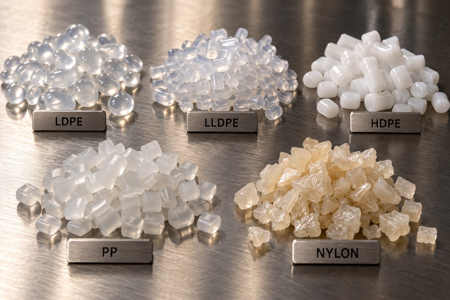
Polyethylene dominates the film industry by volume, but treating "PE" as a single material is a fast path to trouble. The three main grades — LDPE, LLDPE, and HDPE — each behave differently inside the extruder and place distinct demands on screw design.
LDPE (Low-Density Polyethylene) is the classic polyethylene blown film extrusion material. Its highly branched molecular structure gives it a broad processing window and relatively low viscosity under shear, making it forgiving on most standard screws. LDPE melts readily at processing temperatures in the range of 160-200 degrees C and tolerates minor variations in screw compression ratio without dramatic quality swings. It is the workhorse behind general-purpose packaging bags, agricultural film, and shrink wrap. If you are commissioning your first blown film line and running straightforward packaging products, LDPE is often the starting point.
LLDPE (Linear Low-Density Polyethylene) is where things get difficult — and where screw selection becomes genuinely critical. LLDPE's linear molecular architecture gives it superior puncture resistance and tensile strength compared to LDPE, which is why it dominates stretch film and heavy-duty bag applications. But that same structure creates significantly higher viscosity under processing conditions and much greater torque demand on the extruder drive.
The practical impact is striking. Industry data from blown film screw manufacturers shows that an extruder running LDPE comfortably at around 80 rpm can max out on motor torque at roughly 30 rpm when switched to LLDPE — a dramatic reduction in achievable output. Running LLDPE on an LDPE-optimized screw is one of the most common mistakes in pe blown film extrusion. The fix is a barrier screw design with a strong mixing section and channel geometry matched to LLDPE's rheology, typically at an L/D of 30:1 or higher.
Processing temperatures for LLDPE generally run between 170-220 degrees C, overlapping with LDPE but demanding tighter control because LLDPE is less forgiving of inconsistent melt homogeneity. Many real-world production lines run LDPE/LLDPE blends, and the screw must always be designed for the LLDPE fraction since it dictates the processing difficulty of the blend.
HDPE (High-Density Polyethylene) brings yet another profile. Its tightly packed, minimally branched chains create a sharper melting point and higher crystallinity than LDPE or LLDPE. HDPE requires a screw with a lower compression ratio — typically around 3:1 to 3.5:1 — to avoid excessive shear heating that degrades the polymer. Processing temperatures range from 180-230 degrees C. In blown polyethylene film production, HDPE is processed using a high-stalk bubble technique that allows the film to crystallize more gradually, producing the thin, stiff films used in vest-style shopping bags and thin liners. Good melting and mixing are essential because the thin gauges common in HDPE film magnify any melt-quality imperfection.
Polypropylene, Barrier Resins, and Specialty Polymers
Polypropylene (PP) enters the film picture primarily through cast film extrusion, where it produces CPP (Cast Polypropylene) films prized for heat sealability, moisture resistance, and high clarity. PP processes at higher temperatures than PE — typically 200-260 degrees C — and requires careful thermal management because it is more prone to oxidative degradation at elevated temperatures. Screws for PP film generally need an L/D of 28:1 to 32:1, with barrier designs preferred for optimal melt uniformity. Worth noting: MOPP material — metallized oriented polypropylene — starts as a PP film that is later oriented and vacuum-metallized to create the reflective barrier layers common in snack packaging and decorative lamination. While MOPP material itself is produced through a separate orientation and metallization process, the base PP film still depends on a well-configured cast extrusion line to establish the starting substrate quality.
PA (Polyamide/Nylon) and EVOH (Ethylene Vinyl Alcohol Copolymer) are the two primary barrier resins in multilayer film structures. Neither is typically extruded as a standalone film in packaging. Instead, they appear as thin functional layers within co-extruded structures — often just 3-15 microns thick — sandwiched between polyethylene skins and bonded by tie-layer adhesive resins.
PA provides excellent puncture resistance and mechanical toughness alongside moderate oxygen and aroma barrier performance. It processes at approximately 230-270 degrees C and is highly hygroscopic, meaning it must be thoroughly dried before extrusion to prevent moisture-induced degradation that shows up as bubbles, streaks, or reduced barrier performance in the finished film.
EVOH delivers extraordinary oxygen barrier capability — oxygen transmission rates as low as 0.5 cc per square meter per day, orders of magnitude below polyethylene. But EVOH is moisture-sensitive in terms of barrier performance (humidity degrades its OTR), which is why it is always encapsulated between moisture-resistant PE layers in multilayer structures. Processing EVOH requires precise temperature control within plus or minus 1 degree C to prevent thermal degradation, and screws with L/D ratios of 25:1 to 35:1 and compression ratios of 2.5:1 to 4:1 to handle its high-viscosity melt. Each barrier resin in a co-extrusion setup needs its own dedicated extruder with screw geometry specifically optimized for that material — sharing a screw designed for PE will result in incomplete plasticization and compromised barrier layer integrity.
Emerging bio-based polymers — including PLA (polylactic acid) and bio-PE derived from sugarcane ethanol — are gaining traction as sustainability mandates tighten globally. These materials generally process on conventional film equipment with modified temperature profiles and screw designs, though processing windows are often narrower and drying requirements more stringent than conventional petrochemical resins. They represent a growing niche rather than a displacement of mainstream polyethylene film extrusion, but forward-looking line specifications increasingly account for bio-resin compatibility.
Matching Your Resin to Your Machine
The table below maps each major polymer to its preferred equipment type, screw configuration, processing temperature range, and primary end-use applications. Use it as a starting reference when evaluating which machine configuration fits your target product — then validate with your resin supplier's specific processing guidelines, since grades within each polymer family can vary significantly.
| Polymer Type | Preferred Machine Type | Typical Screw L/D | Processing Temp Range | Primary Applications |
|---|---|---|---|---|
| LDPE | Blown (dominant), Cast | 28:1 - 30:1 | 160-200 degrees C | General packaging bags, agricultural film, shrink wrap |
| LLDPE | Blown, Cast | 30:1 - 33:1 | 170-220 degrees C | Stretch film, heavy-duty bags, FFS packaging, blends with LDPE |
| HDPE | Blown (high-stalk) | 28:1 - 30:1 | 180-230 degrees C | Vest/shopping bags, thin liners, high-strength commodity films |
| PP (CPP) | Cast (dominant) | 28:1 - 32:1 | 200-260 degrees C | CPP packaging, heat-seal layers, lamination substrates, MOPP base film |
| PA (Nylon) | Blown or Cast (co-extrusion layer) | 28:1 - 33:1 | 230-270 degrees C | Barrier layer in food packaging, thermoforming films, retort pouches |
| EVOH | Blown or Cast (co-extrusion layer) | 25:1 - 35:1 | 190-230 degrees C | Ultra-high oxygen barrier layer in MAP, meat packaging, pharmaceutical films |
| PLA (Bio-based) | Cast (primary), Blown | 24:1 - 30:1 | 170-210 degrees C | Compostable packaging, fresh produce wraps, specialty retail bags |
A few patterns jump out from this mapping. Polyethylene grades — the backbone of polyethylene film extrusion — are the most versatile, running on both blown and cast platforms with relatively accessible screw designs. Barrier resins like PA and EVOH, by contrast, demand dedicated extruders with specialized screw geometry and tight thermal control, making them viable only in multilayer co-extrusion setups where each layer gets its own optimized processing path.
The practical takeaway? Never specify a line based on output rate alone. Start with the resin — or the resin combination your target product requires — and let the material's processing demands drive your screw, barrel, temperature, and die selections. A machine that runs 300 kg/hr of LDPE beautifully may struggle to push 180 kg/hr of LLDPE through the same screw, or degrade your EVOH barrier layer because the temperature control is not tight enough. The polymer dictates the machine, not the other way around.
Matching resin to equipment is half the selection puzzle. The other half — evaluating production volume, budget constraints, and the supplier behind the machine — shapes whether that match actually delivers consistent results on your production floor.
How to Choose the Right Film Extrusion Machine
You have spent seven sections absorbing process fundamentals, configuration trade-offs, technical parameters, and resin behavior. All of that knowledge is valuable — but it is also scattered across dozens of variables. When procurement day arrives and you are staring at quotations from three different blown film extrusion machine manufacturers, how do you actually decide?
The answer is surprisingly simple in structure, even though the details get technical fast. You work backward. Start with the product your customer is buying, define the film properties that product demands, and let those requirements pull you toward the right machine type, configuration, and capacity. Reverse-engineering the decision this way prevents the most expensive mistake in film extrusion: buying a machine optimized for a product you do not actually make.
Define Your End Product and Film Requirements
Before you open a single supplier catalog, sit down with your sales team and your largest customer specifications. Write out the answers to these questions with real numbers — not ranges you hope to cover someday, but the specific products generating revenue today and in the next 18 months.
- Identify your primary film product. Are you producing grocery bags, stretch wrap, barrier pouches, agricultural mulch, or medical packaging? Each product category points toward a fundamentally different machine architecture. A factory producing shopping bags needs a blown film line. A stretch wrap operation almost certainly needs a cast line.
- Specify the film structure. Is a single-layer film sufficient, or does your customer require a multilayer construction with barrier properties, recycled-content cores, or differentiated skin layers? This determines whether you need a monolayer, ABA, ABC, or 5+ layer co-extrusion setup.
- Pin down the thickness range. Write your most common running gauge and your full specification window in microns. A machine optimized for 80-micron agricultural film will struggle to produce 25-micron packaging film at acceptable quality — the screw, die gap, cooling system, and winding tension are all sized differently.
- Define critical film properties. Does your customer measure dart impact, tensile strength in both MD and TD, haze, gloss, coefficient of friction, or oxygen transmission rate? If your customer does not measure it, do not over-specify it — every additional performance requirement potentially adds capital cost to your line.
- Map downstream processing. Will the film go directly to printing, lamination, automatic bag-making, or form-fill-seal equipment? Downstream compatibility requirements — surface energy for ink adhesion, gauge consistency for seal-bar registration, roll hardness for unwinding tension — feed back into machine specifications that many buyers overlook until commissioning day.
- Lock in your primary resin. As the previous section demonstrated, your polymer choice determines screw geometry, barrel temperature profile, and die configuration. An LLDPE-heavy product mix demands a different drive and screw design than an LDPE-only operation, and barrier films with EVOH or PA require dedicated co-extrusion extruders.
A real-world example illustrates why this step matters so much. A packaging factory in Surabaya, Indonesia purchased a monolayer blown film line and then discovered — six months later — that their largest supermarket customer required 20% recycled content in shopping bag film. A monolayer machine cannot hide recycled PE behind virgin skin layers. The factory owner ended up selling that machine at a loss and ordering an ABA 3-layer line, absorbing roughly $12,000 in lost equipment value, half a year of rejected orders, and a damaged customer relationship. Starting with the end product — and its evolving requirements — would have prevented the entire chain of mistakes.
Production Volume and Budget Considerations
Your target product tells you what to build. Your production volume tells you how big to build it. And your budget determines how much automation and redundancy you can afford along the way.
Consider output requirements first. A datasheet might advertise 200 kg/hr, but that number typically reflects a reference condition — often 50-micron LDPE at a specific width and blow-up ratio. Your real-world output will differ based on film thickness, resin type, and ambient factory conditions. HDPE, for instance, runs 15-20% slower than LDPE on the same machine because its lower melt strength limits haul-off speed. In tropical factories without climate control, summer output can fall 10-20% below winter levels because warmer cooling air removes less heat from the bubble. A practical rule: take the supplier's quoted output at your specific gauge, width, and material, then reduce it by 15% for baseline capacity planning.
Machine size scales with volume requirements in ways that are not always linear. Larger screw diameters increase throughput roughly proportional to the square of the diameter — but they also require larger gearboxes, stronger frames, and more floor space. Multilayer configurations multiply capital cost by 1.5x to 4x or more above a baseline monolayer line, depending on layer count and automation level. A complete monolayer blown film line can start around $18,000-$45,000 for entry-level systems, while ABA 3-layer lines typically fall between $35,000-$90,000, and fully equipped ABC lines with IBC, automatic air rings, and gravimetric dosing can exceed $150,000.
Automation level is the third axis. Servo-driven extruders reduce energy consumption by 12-18% compared to conventional AC motors. Automatic air rings compensate for ambient temperature drift without operator intervention. Gravimetric blenders maintain precise layer ratios in co-extrusion setups. Each feature adds upfront cost but reduces operating expense per kilogram over the machine's 8-12 year service life. For lines running above 6,000 hours annually, the energy savings alone from servo drives typically recover the cost premium within 18-24 months.
Evaluating Machine Suppliers and OEM Support
Two quotations can look nearly identical on paper — same screw diameter, same output rating, same layer configuration — and deliver wildly different results on your production floor. The difference almost always comes down to the supplier behind the numbers.
When comparing blown film extruder manufacturers or film extruder suppliers, move beyond the datasheet and investigate the support ecosystem. The machine itself is only as reliable as the components inside it and the people who stand behind them. Here is what to evaluate:
- Technical consultation depth. Does the supplier ask about your end product, resin, and downstream processing before recommending a configuration? Or do they push a standard model? A blown film machine supplier that starts by understanding your film product — not your budget — is more likely to deliver equipment that actually fits your production reality.
- Component quality and sourcing transparency. Ask what brands are used for drives, temperature controllers, contactors, and relays. Globally available brands — Siemens, Schneider, Omron, Delta, ABB — mean local replacement availability. Unfamiliar domestic components that require weeks to ship can cost thousands in downtime for want of a $50 part.
- Screw and barrel sourcing. The screw-barrel assembly is the most critical wear component on any extruder, and its quality directly affects melt consistency, output stability, and operating life. Look for suppliers — or specialist component manufacturers — who engineer screw barrels specifically for film extrusion applications rather than offering generic designs. For example, NANHAIYA specializes in custom and replacement single screw barrels purpose-built for pipe, film, sheet, pelletizing, recycling, and general-purpose extrusion lines. Having access to an extruder machine manufacturer with this kind of application-specific expertise means you can source replacement screws matched precisely to your polymer and process — rather than settling for a generic geometry that compromises melt quality.
- Commissioning and training support. Proper on-site commissioning shortens your ramp-up period and verifies that the line meets performance guarantees under real conditions. Suppliers that offer production trials with your actual resin before shipment — and hands-on operator training during commissioning — significantly reduce the risk of startup problems.
- After-sales response time. What is the turnaround for a technical video call? Can the supplier dispatch a service engineer to your country, and at what cost? Is there a local agent or distributor providing first-line support? These questions matter far more than any specification once the machine is running 24/7.
- Spare parts availability and lead time. Ask for a recommended spare parts list and confirm pricing and delivery timelines for wear items — screws, barrels, die lips, heater bands, thermocouples. An extruder machine manufacturer that maintains inventory of common wear parts and offers expedited shipping can save you days of unplanned downtime.
One final checkpoint that separates thorough buyers from rushed ones: request reference film rolls from the blown film machine manufacturer. Ask for samples produced on a machine identical to your quoted configuration, running a similar formulation. Measure gauge uniformity yourself. Run the film through your downstream converting equipment — your bag-making line, your laminator, your form-fill-seal system. If the supplier cannot provide samples from the same machine model, treat that as a risk factor and verify commissioning support more carefully before signing the purchase order.
Choosing the right machine is ultimately a systems decision — product requirements, resin properties, production volume, budget constraints, and supplier capability all interlocking. Get the selection right, and your line pays for itself through years of consistent output. Get it wrong, and even the most impressive datasheet specifications become an expensive reminder that numbers without context are just numbers.
Of course, even a perfectly selected line does not stay perfect forever. Every hour of production wears down critical components — and knowing which parts to monitor, when to replace them, and where to source quality replacements is what keeps your investment running at peak performance long after the warranty expires.
Critical Components That Keep Your Film Line Running
A film extrusion machine is only as reliable as its most worn-out component. You can specify the perfect line, select the ideal resin, and dial in every process parameter — yet none of that matters if a degraded screw is quietly producing inconsistent melt, or a tired air ring is delivering uneven cooling across the bubble. The datasheet told you what the machine could do when it was new. This section tells you what keeps it performing five, eight, or twelve years into service.
Think of your extrusion line like a human body. The screw and barrel are the heart and lungs — without consistent melt delivery, nothing downstream functions properly. The die is the vocal cords, shaping raw output into something useful. The air ring, winders, and gauging systems are the nervous system, providing feedback and control that keep the entire organism in balance. When any one element drifts out of specification, film quality suffers — often before operators notice the change on the roll.
The Screw and Barrel as the Heart of Your Extruder
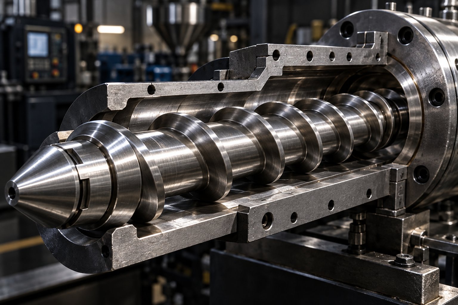
If you could only monitor one component on your entire blown film extruder, it should be the screw-barrel assembly. Every kilogram of polymer passes through this interface, and the clearance between the screw flight tips and the barrel bore determines how efficiently your machine converts pellets into uniform melt.
When a screw and barrel are new, the flight clearance is tight — typically the nominal screw diameter divided by 1,000 per side. For a 90 mm screw, that is roughly 0.09 mm per side. As production hours accumulate, abrasive fillers, glass fibers, calcium carbonate, and even the polymer itself gradually erode the hardened flight tips and the barrel liner. The clearance widens, and polymer starts leaking backward over the flights instead of being pushed forward. The result? Plastics Technology reports that specific rate — the output per RPM — drops measurably as wear progresses. To maintain the same throughput, operators increase screw speed, which in turn raises discharge temperature and accelerates further wear. It is a vicious cycle that erodes both film quality and profitability simultaneously.
The economic impact is real. A blown film application running a 100 mm screw on 1 MI polyethylene at 150 kg/hr might see discharge temperatures climb from 236 degrees C to nearly 246 degrees C as flight clearance doubles — a temperature increase that destabilizes the bubble and forces a rate reduction of up to 13%. On a line running three shifts, that lost capacity translates to thousands of dollars in unrealized production every month.
So when should you replace or refurbish? Industry guidelines from extrusion specialists suggest three common thresholds:
- 4x rule — Replace when flight clearance reaches four times the original clearance.
- Hard-facing depletion — Replace when the stellite or other hard-facing alloy on the flight tips is completely worn through, typically after approximately 0.060 inches of material loss.
- Economic trigger — Replace when the rate reduction and quality degradation cost more than a new or refurbished screw.
For critical-duty applications — medical films, precision barrier packaging — screws should be swapped well before the 4x threshold. A plastic film extruder producing medical barrier film cannot tolerate the gauge variation that a moderately worn screw introduces. Conversely, a blow film extruder running non-critical industrial sheeting might operate economically at higher wear levels before replacement is justified.
A screw should never be refurbished more than three times. Each re-welding of hard-facing material degrades the base metal, increasing the risk of delamination and catastrophic flight-tip failure during production.
Material-matched screw geometry is equally important when sourcing replacements. A screw designed for LDPE has a different compression ratio, channel depth, and mixing-section geometry than one optimized for LLDPE or HDPE. Dropping in a generic replacement screw — one that "fits" dimensionally but was not engineered for your specific polymer — means accepting compromised melt quality from day one. This is precisely where specialist component suppliers add value. NANHAIYA, for example, engineers custom and replacement single screw barrels specifically for film extrusion applications, alongside configurations for pipe, sheet, pelletizing, and recycling lines. That application-specific approach ensures the replacement screw barrel matches your polymer's melt behavior and your machine's mechanical requirements — not just the bolt pattern.
Barrel wear follows a different timeline. An iron-based bimetallic barrel liner typically lasts roughly three times as long as the screw it houses. When the screw is pulled for replacement, always measure the barrel bore at multiple points along its length. Localized wear — often concentrated in the compression zone where solids generate the highest lateral forces — can create dead spots that degrade melt homogeneity even with a brand-new screw installed.
Die, Air Ring, and Downstream Equipment
Beyond the screw and barrel, several other components determine whether your blown film machinery delivers consistent product or gradually drifts out of specification.
The die distributes molten polymer into a uniform annular or flat curtain. Over time, the die lip surfaces develop scoring, corrosion, or resin buildup that disrupts flow distribution. Even a tiny 0.01 mm variation in die gap across the circumference creates visible gauge bands in the finished film. Manual die-lip bolts require periodic re-adjustment based on thickness gauge feedback, while thermal bolts on automated lines need calibration checks to ensure their heating elements still respond linearly to control signals.
The air ring is your primary cooling tool and your first line of defense against bubble instability. Lip wear, debris accumulation in the air plenum, and blower bearing degradation all reduce cooling uniformity over time. Blown film coolers — whether single-lip, dual-lip, or IBC systems — rely on balanced airflow around the full 360 degrees of the bubble. A partially blocked air channel on one side of the ring can create a persistent thin spot that rotates with each oscillation cycle, producing rolls with repeating gauge defects that downstream converters reject.
Thickness gauges — beta-gauge, capacitance, or infrared — are only as accurate as their last calibration. Drift in the gauge sensor means your automatic die-lip control is chasing phantom thickness variations while real ones go uncorrected. Quarterly calibration against traceable film standards is not optional for any line producing film to customer specification.
Winders accumulate wear in lay-on rollers, tension-control brakes, and oscillation mechanisms. A worn lay-on roller creates inconsistent roll density that manifests as telescoping, starring, or blocking during storage. Surface winder contact pressure and center winder torque limits both need periodic verification against the original commissioning values.
Preventive Maintenance and Component Sourcing
Reactive maintenance — waiting for something to break — is the most expensive way to run any extrusion line. Preventive maintenance strategies built around scheduled inspections and proactive component replacement keep unplanned downtime to a minimum and extend the productive life of every major assembly.
Here is a practical maintenance checkpoint framework organized by frequency:
- Daily: Inspect barrel temperature readings across all zones for deviation. Check air ring for debris or resin buildup. Verify winder tension and roll quality on the first rolls of each shift.
- Weekly: Lubricate gearbox and drive components per manufacturer specifications. Inspect nip roller surfaces for wear or contamination. Verify gravimetric feeder calibration against a known weight.
- Monthly: Measure screw flight clearance if the screw is accessible, or track specific rate (kg/hr per RPM) as a proxy for wear progression. Inspect die lip surfaces for scoring or buildup. Calibrate thickness gauges against certified reference film.
- Quarterly: Perform full air ring inspection — disassemble, clean internal plenums, check blower bearings, and verify airflow balance with an anemometer. Inspect heater bands and thermocouples, replacing any that show erratic readings. Review winder tension-control systems and replace worn lay-on roller covers.
- Annually: Pull the screw for visual inspection and dimensional measurement. Measure barrel bore for wear at feed, compression, and metering zones. Inspect die internals and re-polish flow surfaces if needed. Verify barrel alignment — misalignment is a leading cause of accelerated wear, especially on long extruders.
A critical but often overlooked element of any maintenance program is the spare parts strategy. Keeping a spare screw in storage means you can swap immediately when wear reaches the replacement threshold, rather than shutting the line down for weeks while a new one is manufactured and shipped. The same logic applies to heater bands, thermocouples, die lip segments, and air ring components — all items with known wear lifetimes that can be stocked proactively.
Where you source those parts matters as much as when you replace them. OEM parts ensure dimensional compatibility, but specialized component manufacturers often offer superior metallurgy and faster lead times for high-wear items like screws and barrels. NANHAIYA's single screw barrel line, for instance, covers film, pipe, sheet, pelletizing, recycling, and general-purpose extrusion applications — giving operators a single specialist source for replacement screw barrels engineered to match the specific processing demands of each line type, rather than sourcing generic components that may fit the machine but underperform against the polymer.
Consistent maintenance and quality component sourcing are not glamorous topics, and they certainly do not appear on any datasheet. But they are the invisible infrastructure that determines whether your film extrusion machine still hits its rated output and quality targets five years after installation — or whether it has quietly become the most expensive piece of furniture on your production floor.
Frequently Asked Questions About Film Extrusion Machines
1. What is the difference between a blown film machine and a cast film machine?
A blown film machine pushes molten polymer through a circular die and inflates it into a bubble using compressed air, producing film with balanced strength in both directions. A cast film machine spreads the melt through a flat die onto a chilled roll, yielding film with superior optical clarity, tighter gauge tolerance (plus or minus 1-2%), and higher line speeds up to 600 m/min. Blown film suits heavy-duty bags and barrier packaging, while cast film excels in stretch wrap, CPP packaging, and clear display wrapping. Many converters operate both line types to serve diverse product portfolios.
2. How does the blow-up ratio affect film quality in blown film extrusion?
The blow-up ratio (BUR) is the ratio of the inflated bubble diameter to the die diameter. It directly controls the final lay-flat width, film thickness, and the degree of transverse-direction molecular orientation. A higher BUR stretches the film more in the cross direction, improving TD tear strength and enabling thinner gauges. Most polyethylene films run between a BUR of 1.5:1 and 4:1. Pushing the ratio too high risks bubble instability, oscillation, and spiking scrap rates, so operators must balance orientation benefits against process stability using internal bubble cooling and automatic die-lip adjustment.
3. When should I replace the screw and barrel on my film extruder?
Industry guidelines recommend replacement when flight clearance reaches four times its original value, when hard-facing alloy on the flight tips is fully worn through, or when the cost of lost output and quality defects exceeds the price of a new screw. For critical applications like medical barrier films, screws should be swapped well before the 4x threshold. Tracking specific rate — output in kg/hr per RPM — over time provides an indirect but reliable wear indicator. Sourcing replacement screw barrels from specialists like NANHAIYA, who engineer components specifically for film extrusion applications, ensures the geometry matches your polymer and process requirements rather than settling for a generic fit.
4. What polymers can I run on a film extrusion machine?
Common polymers include LDPE for general packaging bags (160-200 degrees C), LLDPE for stretch film and heavy-duty sacks (170-220 degrees C), HDPE for thin shopping bags (180-230 degrees C), and PP for CPP packaging via cast extrusion (200-260 degrees C). Barrier resins like PA and EVOH require dedicated extruders in multilayer co-extrusion setups due to their distinct processing demands. Each polymer dictates specific screw geometry, compression ratio, and L/D ratio — running LLDPE on an LDPE-optimized screw, for instance, can reduce achievable output by more than 60% due to excessive torque demand.
5. How do I choose between a monolayer and multilayer film extrusion line?
Start with your end product requirements. Monolayer lines suit commodity films like basic poly bags, industrial wrap, and simple agricultural covers, offering lower capital cost and operational simplicity. Multilayer co-extrusion becomes necessary when your product demands barrier properties (oxygen or moisture resistance), recycled-content cores hidden behind virgin skins, or differentiated functional layers such as seal, structure, and print surfaces. ABA configurations handle recycled-core applications with two extruders, ABC setups enable three distinct layers, and five-layer lines with EVOH barrier cores serve high-barrier food and medical packaging. Each added layer increases capital cost by roughly 50-100% per step but opens access to higher-margin market segments.
Written by
Nanhaiya Technical Team
Zhoushan Nanhaiya Plastic Machinery Co., Ltd.
The Nanhaiya technical team supports screw and barrel manufacturing projects through application review, technical communication, custom manufacturing coordination, and production and quality control.
Discuss Your Application
Related Articles
More insights on screw barrel technology and plastics processing.
PVC Pipe Making Machine: What No Supplier Will Tell You First
Oct 21, 2026
Learn what a PVC pipe making machine really includes, how each component works, extruder types compared, maintenance schedules, defect fixes, and buying tips.
Read Article
Raw Scrap to Perfect Pellets: Plastic Pelletizing Machine Guide
Oct 19, 2026
Learn how a plastic pelletizing machine converts scrap into uniform pellets. Covers cutting methods, extruder types, quality control, costs, and maintenance.
Read Article
Pet Sheet Extrusion Machine Secrets Your Supplier Won't Share
Oct 15, 2026
Learn how a PET sheet extrusion machine works, key components, specs by production scale, troubleshooting defects, and buyer tips your supplier won't share.
Read ArticleLooking for something else?
Search by material, symptom or product and jump straight to the relevant page.
These are navigation suggestions based on keyword matching — not a quotation, not a delivery commitment, and not a substitute for engineering review. Final specification is confirmed by our engineers against your drawings and processed material.
Need help with screw barrel selection?
Share your machine model, processed material and application. Our team can help with pricing and technical support.