

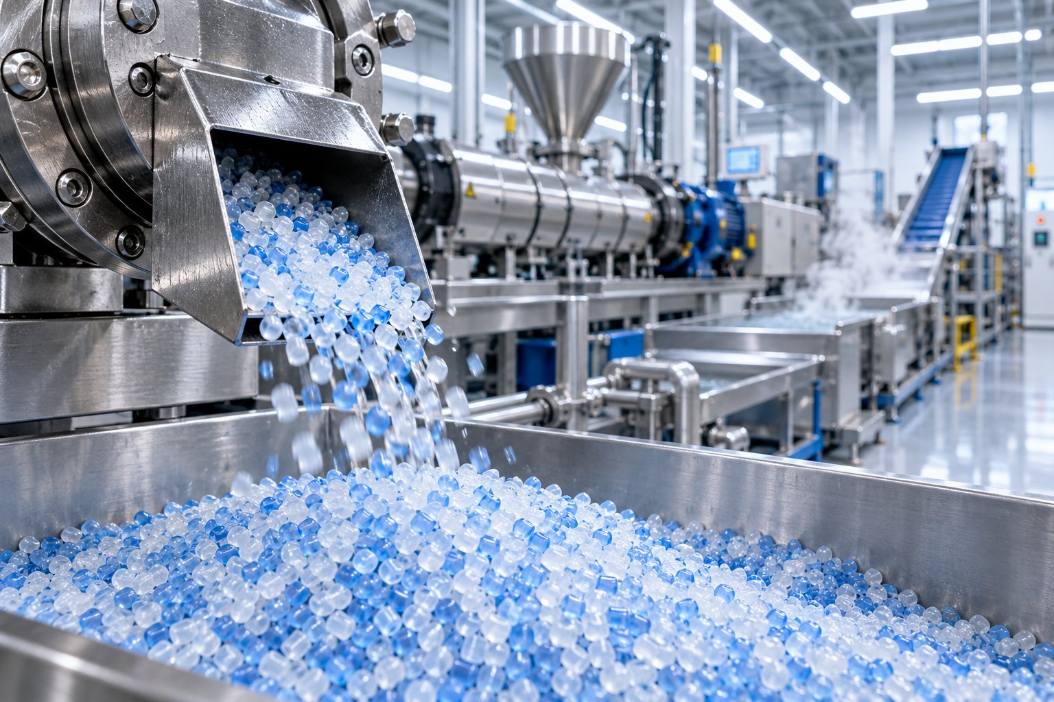
What Is a Plastic Pelletizing Machine and Why It Matters
Imagine a mountain of shredded plastic film, crushed bottles, or factory offcuts sitting on your warehouse floor. None of it can be fed directly into an injection molder or blown-film line. It needs to be transformed into something uniform, flowable, and production-ready. That transformation is exactly what a plastic pelletizing machine delivers.
A plastic pelletizing machine is a precision extrusion system that melts, homogenizes, and cuts raw or recycled plastic into small, uniformly sized pellets — typically 3 to 5 mm — creating standardized feedstock for downstream manufacturing.
What a Plastic Pelletizing Machine Does
At its core, a pelletizer takes loose, inconsistent plastic input — flakes, regrind, powder, or even fluffy film scraps — and converts it into dense, consistently shaped granules. The process works in three broad strokes: the machine melts the plastic inside a heated barrel using screw-driven shear and external heaters, forces the molten material through a filtration system and die, then cuts the emerging strands or melt into individual pellets.
Why pellets specifically? Because virtually every plastics manufacturing method — injection molding, blown film extrusion, sheet extrusion, blow molding — relies on a feedstock that flows predictably through hoppers, screws, and dosing systems. Irregular chunks and tangled film simply cannot do that. Pellets can. They feed evenly, melt consistently, and deliver repeatable results part after part, roll after roll.
Why Pelletizing Matters in the Plastics Industry
So, what is pelletizing in the bigger picture? It is the critical bridge between raw material and usable manufacturing input — and it serves two major streams simultaneously.
In virgin resin compounding, pelletizing turns base polymers, additives, colorants, and reinforcements into ready-to-mold compounds. In post-consumer and post-industrial recycling, it converts washed and sorted waste into sellable recycled pellets that re-enter the supply chain. Without this step, recycled plastic remains low-value regrind that many manufacturers simply will not accept.
What is a pelletizer's real value, then? It is not just a machine — it is the piece of equipment that determines whether your plastic scrap stays waste or becomes a marketable product. The quality, consistency, and commercial value of your output depend heavily on how well the pelletizing stage performs.
Of course, getting from raw scrap to perfect pellets involves more than pressing a start button. The journey passes through several carefully sequenced stages, each one protecting the quality of the final product.
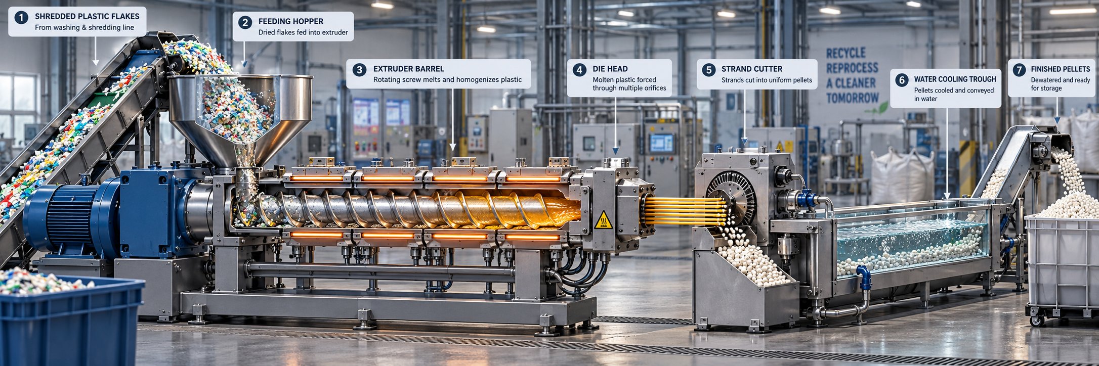
Step-by-Step Pelletizing Process From Raw Plastic to Finished Pellets
A plastic pellet making machine does not operate in isolation. It sits at the heart of a larger production line, and every stage before and after it shapes the quality of the final granule. Think of the entire process as a chain of quality gates — a weak link anywhere upstream creates defects that show up in your finished pellets as black specks, bubbles, inconsistent sizing, or poor bulk density.
Here is the complete plastic pelletizing workflow, broken into its core stages:
- Collection and sorting — Separate polymers by type and color; remove metals with magnets and detectors.
- Shredding or granulation — Reduce material to uniform flakes, typically 5 to 12 mm.
- Washing — Strip away dirt, labels, adhesives, oils, and other surface contaminants.
- Drying — Remove moisture through mechanical dewatering and thermal drying.
- Extrusion and melt filtration — Melt, homogenize, degas, and filter the polymer.
- Die cutting and pelletizing — Shape and cut the molten plastic into discrete pellets.
- Cooling, classification, and packaging — Cool pellets, screen out fines and oversized pieces, then bag or store.
Each step builds on the previous one. Skip or shortcut any stage, and you will "chase problems" in the extruder that no amount of downstream adjustment can fix.
Upstream Preparation and Feeding
Before plastic ever touches the extruder barrel, it needs to be properly prepared. This upstream preparation phase is arguably the cheapest and most effective way to improve your pellet quality.
Shredding and size reduction come first. Raw scrap — whether rigid containers, film rolls, or production offcuts — must be reduced to a consistent flake size. Why does uniformity matter here? Because oversized pieces melt unevenly inside the extruder, destabilizing melt pressure and producing pellets with inconsistent properties. Most systems target flakes in the 5 to 12 mm range, depending on the polymer and the extruder feeding system.
Films present a particular challenge. Lightweight, fluffy LDPE or PP film can bridge inside hoppers and starve the extruder, causing surging output. Many plastic recycling pelletizing lines solve this with a compactor or densifier that uses frictional heat to pre-shrink and agglomerate the film before it enters the screw.
Washing follows shredding. Friction washers, float-sink tanks, and hot-wash modules strip away dirt, sand, paper labels, adhesive residues, and oils. Clean flakes melt more consistently, filter more easily, and produce pellets free of black specks and odor. For PET specifically, residual sugars and label glue can cause yellowing during extrusion — problems that trace directly back to inadequate washing.
Drying is the final upstream gate. Surface moisture must be driven off before the material enters the barrel. Moisture trapped in the melt turns to steam, creating bubbles and voids inside pellets. Centrifugal dryers handle surface water quickly, while thermal or desiccant dryers bring moisture content down to the tight tolerances that hygroscopic polymers like PET demand. And metal detection — installed between drying and feeding — catches ferrous and non-ferrous contaminants that could gouge screws, barrels, and die plates.
Extrusion, Melt Filtration, and Pellet Cutting
The extruder is where plastic pelletizing truly begins. Dried flakes enter the barrel through gravimetric or volumetric feeders that control the exact flow rate. Inside the barrel, the rotating screw applies progressive shear and heat, transforming solid flakes into a homogeneous molten stream.
Temperature stability across the barrel zones is critical. Too much heat degrades the polymer; too little leaves unmelted particles that clog downstream equipment. Many lines also incorporate vacuum degassing ports at one or two positions along the barrel. These vents extract trapped air, residual moisture, and volatile organic compounds — reducing bubble defects and improving pellet surface finish.
The molten polymer then passes through a screen changer for melt filtration. Woven metal mesh screens, supported by a breaker plate, catch unmelted gels, carbonized particles, metal dust, and cross-linked fragments before they reach the die. As contaminants accumulate, the screen's open area decreases and upstream pressure rises. Hydraulic or automatic screen changers allow operators to swap loaded screens without stopping the line — a feature that becomes essential when processing post-consumer recycled material with higher contamination loads.
After filtration, the clean melt is forced through precision-drilled die orifices. What happens next depends on the cutting method. In strand pelletizing, the melt exits as continuous ropes that travel through a water bath before being drawn into a rotary cutter. In die-face systems — such as water-ring or underwater pelletizers — high-speed knives cut the melt directly at the die face, and the freshly cut pellets are immediately quenched by water contact. Each approach produces a different pellet shape and suits different materials, a topic explored in detail in the next section.
Cooling, Classification, and Packaging
Freshly cut pellets are hot and, depending on the cutting method, wet. Cooling and drying must happen quickly to prevent pellets from sticking together or deforming.
Water-bath cooling is standard in strand pelletizing — strands pass through a long trough of chilled water before reaching the cutter. In die-face systems, the water ring or underwater chamber handles cooling and cutting simultaneously. Air cooling serves a different purpose: it is used for moisture-sensitive materials like PVC or certain biodegradable compounds where water contact could degrade the polymer. After cooling, a centrifugal spin dryer strips residual surface water from the pellets.
Next comes classification and screening. Vibrating screens or sieve decks separate out fines (undersized dust and fragments) and any oversized or fused pellets. This step ensures that every pellet leaving the line falls within a consistent size window — typically 3 to 5 mm — so downstream feeding systems run without bridging or uneven dosing.
Finally, the screened pellets move to storage silos or directly to bagging stations. Automated weighing and sealing systems package the finished product for shipment or warehousing. Quality assurance checks at this stage may include visual inspection for specks and discoloration, bulk density measurement, melt flow index testing, and moisture content verification.
The entire flow — from raw scrap entering the shredder to sealed bags of finished pellets — represents a systems-level operation. Every module in the line must be sized and synchronized with every other module. And the performance of the whole system often hinges on a single decision point: which type of cutting and cooling technology best matches your material. That choice deserves a closer look.
Types of Pelletizing Systems and Cutting Methods Compared
Choosing the right pelletizer cutter technology is one of the most consequential decisions you will make when configuring a pelletizing line. The cutting method determines pellet shape, throughput ceiling, material compatibility, and even how much floor space the system occupies. Four major pelletizing systems dominate the industry — strand, water-ring, underwater, and air-cooled hot-face — and each one handles molten polymer in a fundamentally different way.
The core distinction is timing. In strand pelletizing, the polymer cools and solidifies before it is cut. In die-face systems — water-ring, underwater, and hot-face — pellets are cut while the melt is still molten and cooled afterward. That single difference drives most of the trade-offs in pellet quality, automation potential, and operating cost.
Strand Pelletizing and Water-Ring Systems
Strand pelletizing is the most widely used entry-level method and a staple in toll compounding operations. Molten polymer exits a multi-hole strand die, travels through a water bath or water slide for cooling, passes an air knife for surface drying, and finally enters a rotary cutter that shears the solidified strands into cylindrical pellets. The result is a classic cylindrical granule — the shape you will recognize in most commercial compounds.
Why is it so popular? Cost and simplicity. A strand system requires the lowest capital investment of any pelletizing setup, and cleaning between color or material changes is fast and straightforward — a real advantage for compounders juggling frequent job changes. It also handles a broad range of polymers, from polyolefins to engineering resins like ABS and PA.
The trade-offs, however, are real. Operators often need to manually guide dozens of strands over guide rolls during startup — a labor-intensive step that limits automation. Polymers with poor melt strength, such as certain PP grades or PET, can cause strands to droop or break in the water bath, leading to dropped strands and scrap. Cutting solidified material also accelerates blade wear and generates more dust and fines compared to die-face methods. And because the water trough can stretch several meters, strand systems carry a larger factory-floor footprint.
Water-ring pelletizing occupies the middle ground between strand cutting and full underwater systems. Here, molten polymer exits a circular die plate and is immediately cut at the die face by rotating knives — much like a hot-face system. The freshly cut pellets are flung outward into a ring of water that spirals around the cutting chamber, providing initial quenching. The pellet-water slurry then flows to a cooling trough and on to a centrifugal dryer.
Water-ring systems are the most compact of the major pelletizing systems, cost less than underwater pelletizers, and offer a useful degree of automation with minimal operator intervention. They produce rounded, slightly flattened pellets — sometimes compared to small aspirin tablets. However, they work best with high-melt-strength polymers like polyolefins and polystyrene. Heat-sensitive or low-viscosity materials can cause problems, and throughput capacity tops out well below what underwater systems achieve.
Underwater and Hot-Face Pelletizing
Underwater pelletizing (UWP) represents the high end of pelletizing technology. Like water-ring systems, the melt exits a circular die plate and is cut by rotating knives at the die face. The critical difference is that the entire cutting chamber is flooded with temperature-controlled process water, so each pellet is fully immersed the instant it is formed. Surface tension forces shape the molten drops into near-perfect spheres before they solidify — a geometry that improves hopper flow and increases bulk density.
The advantages scale with complexity. UWPs deliver the highest throughput of any system — designs can exceed 20,000 kg/h — and handle virtually any polymer, including low-viscosity hot melts and sticky elastomers. Automation potential is extensive: PLC-controlled blade pressure, in-line die-plate grinding, and water bypass systems allow startups and cutter-head changes in seconds. Dust and fines are minimal because the polymer is cut in its molten state, and the enclosed water circuit makes the system remarkably quiet.
The flip side? Underwater systems carry the highest capital cost and the most complex maintenance profile. Die freeze-off — where reduced melt flow allows polymer to solidify inside the die holes — is a risk that demands consistent upstream pressure. Certain crystalline polymers like nylon and PET can also be prone to freeze-off if process water temperature is not carefully managed.
Hot-face air-cooled pelletizing takes a different approach to the cooling side. Rotating knives cut the melt at the die face — identical in principle to water-ring and underwater methods — but instead of water, a forced airstream captures the pellets, quenches their surface, and conveys them to a fluidized bed or cooling drum for final solidification.
This water-free design makes hot-face air-cooled systems the go-to choice for moisture-sensitive materials: PVC compounds, chemically crosslinked polyethylene (XLPE), certain biodegradable resins like PLA and PBAT, and select medical-grade formulations. Eliminating the drying step simplifies the downstream line and saves energy. Pellet shape is typically spherical to slightly irregular, depending on the polymer's melt behavior. Throughput can reach roughly 5,000 kg/h, placing it comfortably between strand and underwater capacities.
How to Choose the Right Cutting Method
With four systems on the table, the decision comes down to a few key questions: What polymer are you processing? What throughput do you need? What pellet shape does your customer require? And what is your budget for capital and ongoing maintenance?
The comparison table below maps each system against the dimensions that matter most. Use it as a starting framework, then validate your shortlist against the specific resin grade and application you are targeting.
| Dimension | Strand Pelletizing | Water-Ring Pelletizing | Underwater Pelletizing | Hot-Face Air-Cooled |
|---|---|---|---|---|
| Pellet Shape | Cylindrical | Rounded / lenticular (tablet-like) | Spherical | Spherical to slightly irregular |
| Throughput Range | Up to ~20,000 kg/h | Up to ~5,000 kg/h | Up to ~20,000 kg/h+ | Up to ~5,000 kg/h |
| Material Suitability | Broad — polyolefins, styrenics, engineering resins, filled compounds | High-melt-strength polymers (PE, PP, PS); limited with heat-sensitive or sticky resins | Nearly universal — polyolefins, engineering plastics, elastomers, hot melts, masterbatch | Moisture-sensitive resins (PVC, XLPE, PLA, PBAT); select polyolefins with high filler |
| Cooling Medium | Water bath or water slide (air-cooled strand option available) | Water ring + cooling trough | Temperature-controlled process water (fully submerged) | Forced air; optional downstream water quench |
| Capital Cost Level | Low | Moderate | High | Moderate |
| Maintenance Complexity | Low to moderate — blade wear from dry cutting; manual strand-up | Moderate — knife wear; hydraulic pressure system | High — die-plate grinding, water system filtration, freeze-off prevention | Moderate — knife and die-face wear; air-handling system upkeep |
A few practical patterns emerge from this comparison. Toll compounders handling frequent color changes often start with strand pelletizing for its easy cleanability. Recyclers processing post-consumer polyolefins at moderate volumes lean toward water-ring systems for their compact footprint and hands-off operation. Large-scale resin producers and masterbatch manufacturers gravitate toward underwater pelletizers for their throughput ceiling, automation, and spherical pellet geometry. And processors working with PVC cable compounds, crosslinked PE, or biodegradable materials find hot-face air-cooled systems indispensable because water contact would compromise the product.
The cutting method, however, is only one half of the equation. The other half — the extruder itself — determines how well the melt is prepared before it ever reaches the die. Single-screw and twin-screw extruders bring very different mixing, venting, and conveying capabilities to the pelletizing line, and matching the right extruder to your application is just as critical as selecting the right cutter.
Single-Screw vs Twin-Screw Extruders in Pelletizing Applications
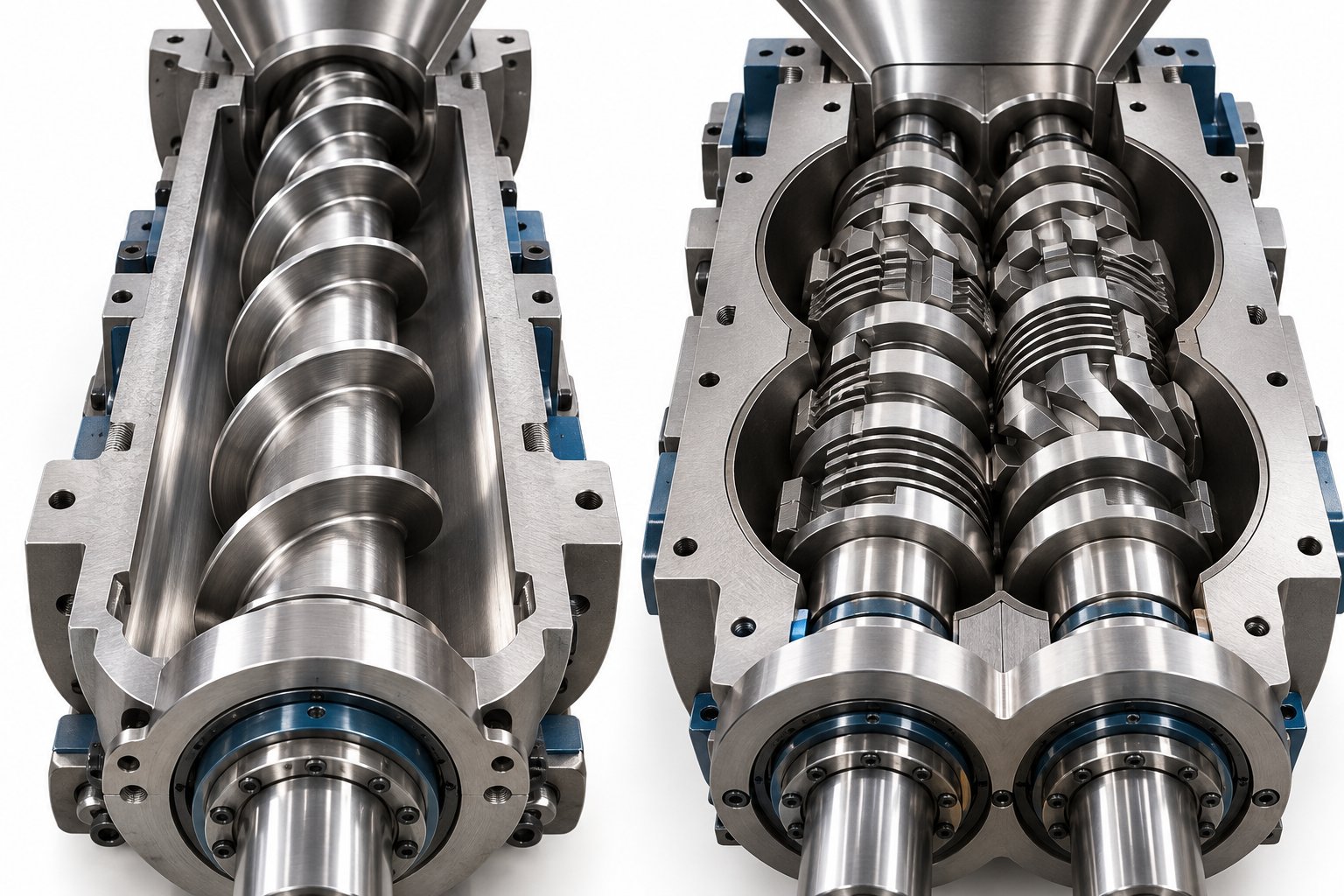
Every extrusion pelletizing machine is built around one central component: the screw. It is the screw that melts, mixes, degasses, and pressurizes the polymer before it reaches the die. Yet screws are not created equal. A single-screw extruder and a twin-screw extruder handle those tasks through fundamentally different mechanisms — and the choice between them shapes everything from pellet homogeneity to the range of materials your line can process.
Single-Screw Extruders for Pelletizing
If your operation recycles clean, pre-sorted streams of one polymer type — think post-industrial HDPE regrind or single-source PP offcuts — a single-screw extruder pelletizer is often all you need. The design is straightforward: one rotating screw inside a heated barrel uses friction and drag flow to convey, melt, and pump the material forward.
That simplicity translates into tangible business advantages. Capital cost sits well below twin-screw territory. Day-to-day operation requires less specialized training. Maintenance is less complex because there is only one screw, one barrel bore, and a simpler gearbox. Energy consumption per kilogram of output tends to be lower for basic melting and re-pelletizing tasks.
The limitations surface when the job demands more than melting and pumping. Single-screw designs rely on friction against the barrel wall to move material forward, which makes them less effective at handling fine powders, low-bulk-density films, or feedstocks with poor flow characteristics. Mixing intensity is moderate at best — adequate for re-melting a consistent input, but insufficient for dispersing pigments, blending multiple resins, or incorporating mineral fillers evenly throughout the melt.
Twin-Screw Extruders for Compounding and Demanding Applications
Parallel co-rotating twin-screw extruders change the equation entirely. Two intermeshing screws use positive displacement to physically pump material forward, independent of friction. This mechanical advantage delivers three capabilities that single-screw systems cannot match: high-intensity distributive and dispersive mixing, efficient multi-stage vacuum degassing, and precise control over shear and residence time.
Why does this matter for pelletizing? Because many pelletizing applications go far beyond simple re-melting. Compounding color masterbatch requires thorough pigment dispersion down to the sub-micron level. Producing glass-fiber-reinforced PA demands gentle fiber incorporation without excessive breakage. Blending incompatible polymers with compatibilizers calls for the kind of intimate mixing that only intermeshing screws provide.
A defining feature of parallel twin-screw technology is its modular barrel and screw architecture. Individual screw elements — conveying flights, kneading blocks, tooth-mixing elements, and reverse-pumping seals — slide onto splined shafts in a sequence tailored to the specific material challenge. The barrel follows the same logic, with interchangeable segments for solid conveying, side feeding, atmospheric venting, and vacuum degassing. Suppliers like NANHAIYA engineer custom parallel twin screw barrels configured for specific compounding, recycling, and masterbatch applications — a level of customization that lets processors fine-tune shear profiles without replacing the entire machine.
This modularity also reduces long-term cost. When abrasive fillers wear down a localized high-shear zone, you replace only the affected screw elements and barrel segments rather than the full assembly.
When to Upgrade to Twin-Screw Technology
How do you know when a single-screw setup is no longer enough? Ask yourself these questions:
- Are you incorporating pigments, stabilizers, or flame retardants that need thorough dispersion?
- Does your process involve blending two or more polymer types with a compatibilizer?
- Are you working with mineral or glass-fiber fillers that require controlled incorporation?
- Do you need multi-stage vacuum degassing to remove moisture, volatiles, or odors from post-consumer feedstock?
- Are you running reactive extrusion — chain extension, grafting, or crosslinking — inside the barrel?
If the answer to any of these is yes, a twin-screw extruder is the preferred platform for your pelletizing machine plastic processing line. The added capital investment pays back through higher product quality, broader material versatility, and the ability to produce value-added compounds rather than generic recycled pellets.
The table below puts the two technologies side by side across the dimensions that drive most purchasing decisions:
| Dimension | Single-Screw Extruder | Twin-Screw Extruder |
|---|---|---|
| Mixing Capability | Moderate — adequate for re-melting consistent, pre-sorted input | High — distributive and dispersive mixing for compounding, masterbatch, and filled systems |
| Throughput Flexibility | Optimized for a narrow throughput window around design capacity | Broad operating range; output adjustable via screw speed and feed rate independently |
| Material Versatility | Best for single-polymer recycling of clean streams (PE, PP, PS) | Handles multi-resin blends, powders, fibers, reactive systems, and thermally sensitive resins |
| Degassing Performance | Limited — typically one vent port | Superior — multiple vacuum and atmospheric venting zones along the barrel |
| Capital Cost | Lower | Higher — offset by broader capability and product value |
| Barrel / Screw Customization | Fixed or semi-modular screw geometry | Fully modular — interchangeable screw elements and barrel segments from suppliers such as NANHAIYA enable application-specific configurations |
| Maintenance Complexity | Simpler — fewer wear components | More complex — but modular design allows targeted replacement of worn segments |
In practice, many recyclers start with a single-screw line for straightforward post-industrial streams, then add a twin-screw system as they move into compounding, masterbatch production, or post-consumer recycling where contamination and material variability demand more processing muscle. The two technologies are not competitors so much as complementary tools in a growing operation's toolkit.
Choosing the right extruder, however, only sets the stage. The next critical question is sizing — matching the entire pelletizing line's capacity to your actual production targets and business scale.
How to Match Pelletizing Machine Capacity to Your Business Scale
A perfectly selected extruder and cutting system still underperform if the line is the wrong size for your operation. An oversized plastic pelletizing line ties up capital in equipment that sits idle most of the week. An undersized one forces you to run around the clock just to meet orders — burning out motors, accelerating wear, and leaving zero room for feedstock surges or unplanned downtime. Getting the capacity right from the start is one of the highest-return decisions you will make.
Micro-Recycling and Startup Operations
If you are launching a small recycling business, running an R&D lab, or testing a new material stream before scaling up, micro pelletizing setups under 200 kg/h are the logical starting point. These compact lines typically pair a 65 to 90 mm single-screw extruder with a strand or water-ring pelletizer, a basic screen changer, and a simple water-bath cooling section.
Capital requirements are modest — often a fraction of what a mid-range system demands. Line configurations are simpler, with fewer auxiliary components and a smaller factory footprint. A 500 kg/h line might need 200 square meters of floor space; a micro pelletizing setup can fit comfortably in under half that area. Staffing needs drop accordingly, often requiring just one or two trained operators per shift.
The trade-off is obvious: limited throughput means limited revenue per hour. But for startups validating market demand, processors exploring post-consumer streams they have never handled before, or universities developing new polymer blends, that constraint is a feature, not a bug. You learn the process at low risk before committing to serious capital.
Small-to-Medium Enterprise Lines
Regional recyclers, toll compounders, and masterbatch producers typically operate in the 200 to 1,000 kg/h range. This is where the pelletizer equipment investment starts to balance meaningfully against production revenue. A mid-range line might center on a 120 mm single-screw extruder or a 65 mm twin-screw system, paired with a water-ring or strand pelletizer and a continuous or semi-continuous screen changer.
At this scale, you gain real output flexibility. Running two shifts at 500 kg/h, for example, delivers roughly 8 to 9 metric tons per day — enough to supply several injection molding customers or build inventory for commodity pellet sales. The line is large enough to justify automation investments like gravimetric feeding, auto screen changers, and PLC-based temperature control, all of which reduce labor dependency and improve pellet consistency.
This tier also opens the door to product diversification. With adequate throughput, you can dedicate production blocks to different polymer grades, colors, or compound formulations without the capacity penalty that would cripple a micro-scale line.
Industrial-Scale Pelletizing Lines
Operations exceeding 1,000 kg/h enter industrial territory — the domain of large resin producers, high-volume post-consumer recycling plants, and integrated petrochemical complexes. Lines at this level often feature 160 mm or larger single-screw extruders, or 75 to 92 mm twin-screw systems for compounding applications, coupled with underwater pelletizers that deliver uniform spherical pellets at rates well above 2,000 kg/h.
At industrial scale, every efficiency gain compounds. A 1% improvement in energy consumption per ton saves thousands of dollars annually. Automated pellet classification, inline quality monitoring, and centralized PLC or SCADA control become standard, not optional. Upstream equipment — shredders, wash lines, dryers — must be precisely capacity-matched to the extruder, because a bottleneck at any stage starves the entire line.
Imagine a wash line capable of producing 1,200 kg/h of clean flakes feeding an extruder rated at only 800 kg/h. That mismatch creates a buffer-management headache and caps your effective output well below what your upstream investment could support. System-level balance is not a luxury at this scale — it is a requirement.
How to Size Your Pelletizing Line
Rather than picking a machine based on peak ambition, work backward from your actual production targets. Here is a practical sizing methodology:
Step 1 — Define your output target. Start with the quantity of finished pellets you need per day, per month, or per year. This is your anchor number.
Step 2 — Calculate required hourly throughput. Divide your daily pellet target by the number of effective operating hours — not scheduled hours. Effective hours account for startup, shutdown, cleaning, screen changes, and minor stoppages. A plant scheduled for 16 hours typically achieves 12 to 13 effective production hours.
Step 3 — Apply a recovery rate. If you are processing post-consumer waste, not every kilogram of input becomes a sellable pellet. Contamination, moisture loss, and material rejected by melt filtration reduce yield. A common recovery rate for post-consumer streams ranges from 80% to 90%, meaning you need to feed more raw material than your pellet target suggests.
Step 4 — Add a capacity margin. Aim for your calculated throughput to land at roughly 70% to 80% of the machine's rated capacity. This headroom absorbs feedstock variability, seasonal surges, and the gradual throughput dip that occurs as wear parts age between replacements.
Step 5 — Size upstream equipment to match. Work backward from the extruder's required feed rate to determine shredder capacity, wash line throughput, dryer capacity, and conveyor speeds. Every upstream module should meet or slightly exceed the extruder's appetite.
The key variables you need to pin down before contacting a supplier:
- Target daily or annual pellet output (in kilograms or metric tons)
- Effective operating hours per day (after deducting downtime)
- Feedstock type and contamination level (determines recovery rate)
- Recovery rate (typically 80%–95% depending on material cleanliness)
- Desired capacity margin (recommended 20%–30% above calculated throughput)
- Polymer type and form (rigid flake, film, fiber, powder — each affects feeding and extrusion behavior)
- Final pellet specification (shape, size, contamination limits required by your buyers)
Running through this framework before requesting quotes ensures you compare pelletizer equipment on a level playing field — and it protects you from the two most expensive mistakes in the industry: buying a line too small to meet demand, or buying one so large it never runs above 50% utilization.
Capacity, though, is only one axis of the decision. The type of plastic you process shapes not just how big the line needs to be, but which pelletizing method, extruder configuration, and downstream handling it requires. Different polymers behave very differently under heat, shear, and cooling — and those differences demand specific processing strategies.
Which Pelletizing Method Works Best for Each Plastic Type
Not every polymer behaves the same way inside an extruder barrel. Some melt lazily and hold their shape well as strands. Others degrade the instant they overheat, crystallize the moment they cool, or cling to every metal surface they touch. These differences in melt behavior, thermal sensitivity, and cooling response are what make the material-to-method match so critical when configuring a plastic pelletizer.
Choosing the wrong pelletizing method for a given polymer does not just create cosmetic pellet defects — it can destroy the resin's molecular weight, contaminate entire batches with degradation byproducts, or accelerate equipment wear at a rate that blows up your maintenance budget. The sections below map the most common polymer families to the cutting systems, extruder types, and processing strategies that suit them best.
Pelletizing Polyolefins — PE, PP, and Their Variants
Polyolefins are the workhorses of the recycling and compounding world, and for good reason — they are among the most forgiving plastics to pelletize. HDPE, LDPE, LLDPE, and PP all process within a relatively wide temperature window, tolerate moderate shear without significant degradation, and are not hygroscopic, so pre-drying is typically unnecessary for clean, dry feedstock.
That said, not all polyolefins behave identically. PP pelletizing, for instance, requires attention to melt flow rate (MFR). High-MFR PP grades have low melt viscosity, which makes strands thin and fragile in a water bath — increasing the risk of strand breakage during startup and steady-state operation. Water-ring pelletizing handles these grades more reliably because the melt is cut at the die face before it has a chance to sag. For standard homo- and copolymer PP grades with moderate MFR, strand pelletizing works perfectly well and remains the lower-cost option.
LDPE and LLDPE films present a different challenge. Their low bulk density means they struggle to feed consistently into an extruder hopper without a compactor or force-feeder. Once inside the barrel, though, they melt and pelletize smoothly. Water-ring systems are especially popular for film recycling lines because they are compact, automated, and tolerate the slight melt-pressure fluctuations that bulky film feedstock often causes.
HDPE — stiffer, denser, and higher in melt viscosity — holds strand integrity well and is an excellent candidate for strand pelletizing. It also processes cleanly in water-ring and underwater systems. For large-volume HDPE compounding operations, underwater pelletizing delivers the highest throughput and the most uniform spherical pellets.
Across the polyolefin family, single-screw extruders handle straightforward recycling of clean, pre-sorted streams with ease. Twin-screw systems become necessary only when the operation involves color compounding, additive incorporation, or blending multiple polyolefin grades with compatibilizers.
Engineering Plastics and Thermally Sensitive Resins
Step outside the polyolefin comfort zone and the processing rules tighten considerably. Engineering plastics and thermally sensitive resins demand more precise control over temperature, moisture, shear, and cooling — and the wrong pelletizing setup can ruin a batch in minutes.
PET (polyethylene terephthalate) is one of the most widely recycled polymers, but PET pelletizing introduces unique complications. PET is highly hygroscopic — it absorbs moisture from the air and must be dried to below 50 ppm moisture content before extrusion. Residual water causes hydrolytic chain scission during melting, which drops the resin's intrinsic viscosity (IV) and weakens the final product. According to the APR's standard laboratory practices, PET flake should be dried at 150 to 160 degrees Celsius in a desiccant dryer for four to six hours before extrusion, with melt temperatures targeting approximately 280 degrees Celsius.
After pelletizing, PET pellets exit the die in an amorphous state — transparent and sticky. If they are not crystallized promptly, they will fuse together in storage. Industrial PET pelletizing lines include a post-pelletizing crystallization step, typically at 160 to 170 degrees Celsius for roughly one hour, followed by solid-state polymerization (SSP) to rebuild the IV lost during melt processing. Strand pelletizing is the most common cutting method for PET recycling, though underwater systems are increasingly used in high-capacity bottle-to-bottle recycling plants.
PA (nylon) shares PET's moisture sensitivity. Thorough desiccant drying is essential, and extrusion temperatures run high — typically 250 to 280 degrees Celsius depending on the PA grade. Nylon's sharp melt-to-solid transition can cause die freeze-off in underwater pelletizing systems if the process water temperature drops too low. Strand pelletizing and underwater systems both work for PA, but operators must monitor die temperature closely and maintain adequate melt pressure to prevent plugged die holes.
PC (polycarbonate) processes at elevated temperatures — around 280 to 320 degrees Celsius — and is sensitive to hydrolysis. Pre-drying to below 200 ppm moisture is critical. PC also has high melt viscosity, which creates substantial backpressure in the extruder and demands robust drive systems. Strand pelletizing is common for PC compounding, particularly when glass fiber reinforcement is involved.
ABS and PS (polystyrene) are more approachable. ABS processes well in the 220 to 260 degrees Celsius range and handles both strand and water-ring pelletizing without major issues. PS, with its low melt viscosity at processing temperatures, is well suited to water-ring systems. Both materials are relatively insensitive to moisture, though ABS benefits from drying to avoid surface splay in the final molded part.
PVC stands apart from every other commodity resin. It degrades thermally through dehydrochlorination — releasing corrosive hydrochloric acid gas — if barrel temperatures exceed a narrow safe window, typically 160 to 190 degrees Celsius depending on the formulation. This thermal sensitivity rules out any pelletizing method that subjects the melt to prolonged heat exposure. Hot-face air-cooled pelletizing is the standard for PVC compounds because it avoids water contact (which can interfere with certain PVC stabilizer systems) and moves pellets away from the die face quickly. Twin-screw extruders with counter-rotating, conical screw geometry are the traditional PVC processing platform, though parallel co-rotating twin-screw systems are also used for rigid PVC formulations.
Filled and Reinforced Compounds
Glass-fiber-filled, mineral-filled, and carbon-fiber compounds introduce a challenge that goes beyond thermal management: abrasive wear. Every filler particle and fiber strand acts like fine sandpaper against the screw flights, barrel wall, die plate, and cutter blades. The higher the filler loading, the faster the wear — and research on twin-screw compounding of glass-fiber-reinforced PP confirms that fiber content significantly influences both fiber breakage and equipment stress.
Twin-screw extruders are the standard platform for fiber-filled pelletizing because they offer downstream side feeding — fibers are introduced after the polymer is already molten, minimizing the shear exposure that breaks fibers. Screw configuration plays a decisive role: using only conveying elements after the fiber feed port preserves fiber length far better than configurations that include kneading blocks in that zone. The same study found that screw configurations without kneading blocks after fiber introduction consistently produced longer fibers compared to designs with kneading elements.
Strand pelletizing is the dominant cutting method for reinforced compounds. The solidified strand absorbs blade impact more evenly than a molten die-face cut, reducing the likelihood of fiber pullout or pellet crumbling. Underwater pelletizing can handle filled materials at high throughputs, but wear on the die plate accelerates significantly — die holes elongate and lose their round profile, which degrades pellet shape over time.
For screws, barrels, and die plates exposed to abrasive fillers, material upgrades are essential. Nitrided steel is the baseline. Bimetallic barrel liners with tungsten carbide or boron alloy coatings extend service life dramatically. Screw elements can be hard-faced with cobalt-based alloys or manufactured from powdered metallurgy tool steels. Without these hardened or coated components, wear rates in a 30% glass-fiber-filled compound can be five to ten times faster than in unfilled resin — turning routine maintenance into a constant production drain.
The table below consolidates the material-to-method mapping for the nine most common polymer types. Use it as a quick reference when specifying your plastic pelletizer configuration.
| Plastic Type | Recommended Pelletizing Method | Preferred Extruder Type | Key Processing Considerations |
|---|---|---|---|
| HDPE | Strand, water-ring, or underwater | Single-screw (recycling); twin-screw (compounding) | High melt strength supports stable strands; no pre-drying needed for clean feedstock |
| LDPE | Water-ring (preferred for film); strand | Single-screw with compactor for film | Low bulk density requires force-feeding or compaction; prone to hopper bridging |
| PP | Water-ring or strand; underwater for high volume | Single-screw (recycling); twin-screw (compounding) | High-MFR grades may break strands — water-ring avoids this; watch for beta-crystallization effects |
| PET | Strand (most common); underwater for high capacity | Single-screw (24:1 to 36:1 L/D); twin-screw also used | Dry to below 50 ppm moisture; melt at ~280 degrees Celsius; crystallize pellets post-cutting; SSP to rebuild IV |
| PA (Nylon) | Strand or underwater | Twin-screw (compounding); single-screw (re-pelletizing) | Hygroscopic — pre-dry thoroughly; risk of die freeze-off in underwater systems; monitor process water temperature |
| PC | Strand | Twin-screw (compounding and blends) | Process at 280 to 320 degrees Celsius; dry below 200 ppm moisture; high melt viscosity creates significant backpressure |
| ABS | Strand or water-ring | Twin-screw (compounding); single-screw (regrind) | Moderate processing window (220 to 260 degrees Celsius); drying recommended to prevent surface splay |
| PS | Water-ring or strand | Single-screw (recycling); twin-screw (HIPS compounding) | Low melt viscosity suits water-ring well; relatively insensitive to moisture; easy-to-process baseline resin |
| PVC | Hot-face air-cooled | Counter-rotating twin-screw (traditional); co-rotating twin-screw (rigid formulations) | Narrow thermal window (160 to 190 degrees Celsius); releases HCl gas if overheated; avoid prolonged water contact with certain stabilizer systems |
A few patterns stand out. Polyolefins give you the widest latitude in cutting method and extruder selection. Engineering plastics tighten the process window and raise the stakes around moisture control. PVC demands a specialized approach from barrel to die face. And filled compounds shift the focus from the polymer itself to the wear resistance of every metal surface it contacts.
Matching your material to the right method prevents most pellet defects before they start. But even a perfectly matched line produces imperfect pellets if process parameters drift, blades dull, or moisture creeps in. Understanding what a good pellet looks like — and diagnosing problems when it does not — is a skill set every operator and quality manager needs.
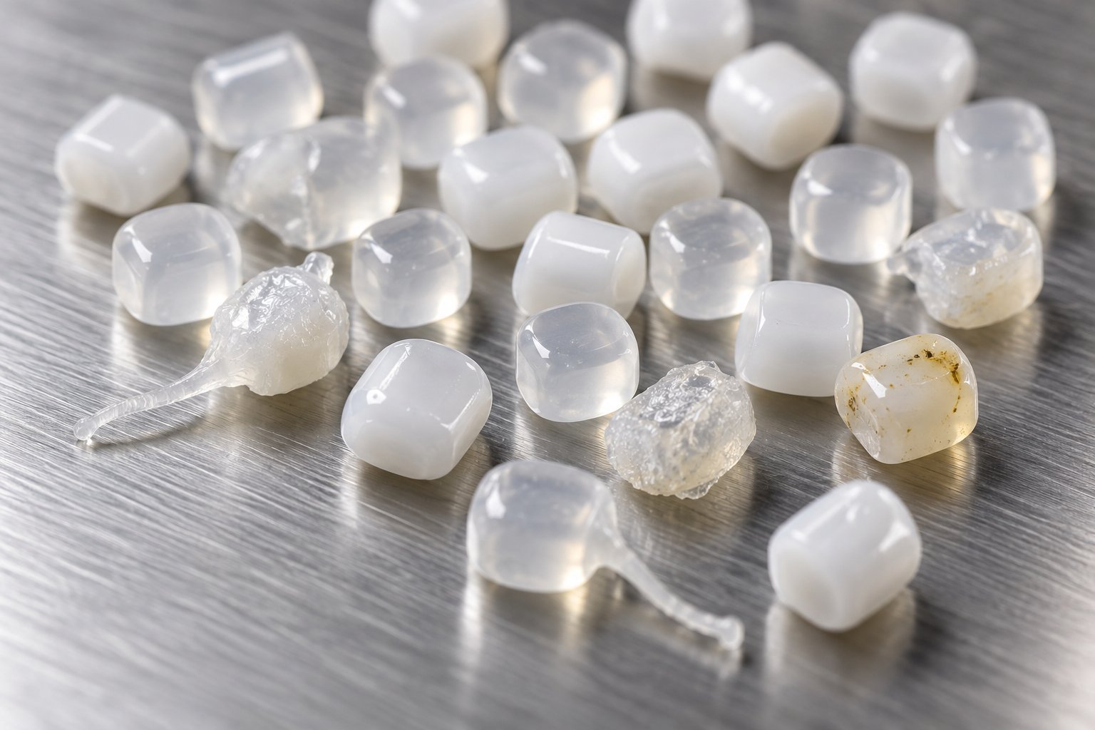
Pellet Quality Control and How to Fix Common Defects
You have selected the right pelletizing system, matched your extruder to your polymer, and dialed in the process parameters. Pellets are flowing off the line. But are they good pellets? A surprising number of operators never define what "good" actually looks like — and that ambiguity costs real money downstream. Inconsistent pelletized plastic causes feeding problems in injection molding hoppers, uneven melt behavior in blown-film lines, and rejected shipments from buyers with tight incoming-material specs. Quality control at the pelletizing stage is not optional — it is where you protect the value of everything that happened upstream.
What Good Pellets Look Like
Before you can spot a defect, you need a clear picture of the target. A high-quality pellet meets five measurable benchmarks:
- Uniform size and shape — Every pellet in the batch should fall within a tight dimensional window, typically plus or minus 0.5 mm. Cylindrical pellets from strand systems should have consistent length-to-diameter ratios. Spherical pellets from underwater systems should show no flattening, tails, or elongation.
- Consistent color — Color should be homogeneous across the pellet surface and from pellet to pellet. Streaks, dark specks, or yellow discoloration signal contamination or thermal degradation inside the barrel.
- Absence of voids or bubbles — Cut a pellet in half and examine the cross section. The interior should be solid and dense. Hollow centers, gas pockets, or foam-like structures indicate trapped moisture or insufficient venting during extrusion.
- Smooth surface finish — The pellet surface should be glossy or uniformly matte, depending on the polymer. Rough, pitted, or shark-skin-textured surfaces point to melt fracture, die wear, or incorrect processing temperatures.
- Bulk density within specification — Consistent bulk density ensures that volumetric feeders in downstream equipment dose the correct mass per cycle. Variations in bulk density typically trace back to inconsistent pellet size, internal voids, or excessive fines mixed into the batch.
Why do these benchmarks matter so much? Because every downstream process — injection molding, extrusion, blow molding — assumes a predictable feedstock. When pellet geometry varies, hoppers bridge. When voids are present, parts develop weak spots. When color shifts, finished products fail visual inspection. Pellet quality is not an abstract metric — it directly determines whether your customers accept or reject the material.
Common Pellet Defects and Their Causes
Even well-maintained pelletizing systems produce defects from time to time. The key is recognizing them early and tracing each one to its root cause. Most defects have multiple possible causes, so the best troubleshooting practice is to change one variable at a time and allow enough production time to observe the effect before making another adjustment.
Here are the defects operators encounter most frequently:
Tails and angel hair. These are thin, whisker-like filaments attached to pellets or floating loose in the batch. They form when the pelletizing cutter blades are dull, when the gap between the blade and die face is too wide, or when die temperature is too low — causing the melt to solidify partially before the cut is complete. Angel hair clogs pneumatic conveying lines, tangles in hopper throats, and creates an immediate downstream nuisance.
Voids and bubbles. Internal cavities inside the pellet — visible when you slice one open — stem from trapped gas. The most common culprit is residual moisture in the feedstock that flashes to steam inside the barrel. Insufficient vacuum degassing, air entrapment from poor screw design, or volatile additives outgassing during extrusion can also create voids. The "popcorn" defect, where pellets expand and become irregularly shaped, represents an extreme version of this problem.
Discoloration. Yellow or brown tinting usually indicates thermal degradation — the polymer spent too long at elevated temperatures, or barrel zone setpoints exceeded the material's safe processing window. Black specks, on the other hand, typically come from carbonized material buildup on screw flights, barrel walls, or inside the die. Contamination from upstream — incompatible polymers, dirt, or residual adhesive — also produces visible color shifts.
Inconsistent pellet size. When pellets vary in length, diameter, or weight within the same production run, the culprit is usually uneven melt flow through the die. Plugged die holes, fluctuating extruder output (surging), misaligned cutter blades, or inconsistent strand take-up speed in strand pelletizing systems all contribute. Non-uniform pellets create dosing errors in downstream equipment and reduce the perceived quality of the finished product.
Twins, chains, and agglomerates. Pellets that fuse together during or immediately after cutting indicate that the cooling medium is not quenching the cut surface fast enough. In underwater and water-ring systems, insufficient water flow, excessive water temperature, or too much melt throughput relative to the cooling capacity all promote sticking. In strand systems, strands that contact each other before fully solidifying produce fused "twin" pellets.
Surface defects — melt fracture and dimples. A rough, sharkskin-like texture on the pellet surface signals melt fracture, caused by excessive die shear stress. Reducing throughput, raising die temperature, or switching to a die with larger orifices usually resolves it. Dimples — small depressions on the pellet surface — form when the interior of a hot pellet shrinks during cooling. They are most common in thick, spherical pellets produced by underwater systems and can be mitigated by adjusting water temperature and die orifice diameter.
How to Prevent Quality Issues
The best approach to pellet quality is prevention, not correction. Most defects trace back to a handful of controllable process variables. Stay on top of these, and you eliminate the majority of quality complaints before they reach your packaging line.
Dry your material properly. For hygroscopic resins like PET, PA, and PC, this means desiccant drying to the manufacturer's recommended moisture ceiling — not just "running the dryer for a while." For polyolefins and other non-hygroscopic polymers, mechanical dewatering and thermal drying should bring surface moisture well below the threshold that causes steam bubbles.
Maintain sharp cutter blades. Dull knives are the single most common cause of tails, angel hair, and inconsistent pellet geometry. Establish a blade inspection schedule based on operating hours and material abrasiveness — filled compounds dull blades far faster than unfilled resins. Replace or resharpen blades before defects appear, not after.
Hold consistent extruder temperature profiles. Thermal degradation and melt fracture both start with temperature control failures. Verify thermocouple accuracy regularly, calibrate PID controllers, and monitor barrel zone temperatures for drift — especially at the die adapter, where heat loss can cause localized cold spots.
Ensure adequate melt filtration. A clogged screen raises upstream pressure, slows output, and can push contaminants through weakened mesh. Switch screens proactively based on pressure differential, not just visual inspection or calendar intervals. Continuous or hydraulic screen changers make this seamless on high-throughput lines.
Monitor die condition. Worn, corroded, or partially plugged die holes create uneven melt distribution, which produces mismatched pellet sizes. Periodic die-plate inspection and cleaning — along with calculating the percentage of open die holes — ensures you are not compensating for a degraded die by adjusting everything else on the line.
The table below consolidates the most common defects, what they look like, their likely root causes, and the corrective actions that resolve them. Print it, laminate it, and keep it at the operator station — it is the fastest path from "something looks wrong" to "here is what to fix."
| Defect | Visual Description | Likely Root Cause | Corrective Action |
|---|---|---|---|
| Tails / Angel Hair | Thin filaments or whiskers attached to pellets or loose in the batch | Dull cutter blades; excessive blade-to-die gap; die temperature too low | Replace or resharpen blades; adjust blade-to-die clearance; increase die temperature |
| Voids / Bubbles | Hollow centers or gas pockets visible in cross-sectioned pellets | Residual moisture in feedstock; insufficient vacuum degassing; air entrapment | Improve material drying; verify vacuum vent operation; check screw seal zones |
| Discoloration (Yellowing) | Yellow or brown tinting across pellet surface | Thermal degradation from excessive barrel temperature or prolonged residence time | Lower barrel zone temperatures; increase throughput to reduce residence time; check for dead spots in the melt path |
| Black Specks | Small dark particles embedded in or on the pellet surface | Carbonized buildup on screw, barrel wall, or die; upstream contamination | Purge the extruder; clean screw and die; improve upstream washing and metal detection |
| Inconsistent Size | Pellets vary noticeably in length, diameter, or weight | Plugged die holes; extruder output surging; misaligned cutter; uneven strand take-up speed | Clean or replace die plate; stabilize extruder feed rate; realign cutter assembly; calibrate strand puller speed |
| Twins / Chains / Agglomerates | Two or more pellets fused together | Inadequate cooling water flow or temperature; melt throughput exceeds cooling capacity | Increase cooling water flow; lower water temperature; reduce throughput or raise cutter speed |
| Melt Fracture (Sharkskin) | Rough, ridged, or sharkskin-like pellet surface texture | Excessive die shear stress from high throughput or undersized die orifices | Reduce output rate; raise die temperature; use a die with larger orifice diameter |
| Dimples | Small surface depressions or craters on pellets | Internal shrinkage during cooling of thick pellets | Adjust process water temperature; reduce pellet size via die orifice or cutter speed change |
| Dust / Fines | Fine powder mixed in with finished pellets | Dull blades fracturing instead of cleanly shearing; brittle polymer; excessive pellet conveying speed | Sharpen or replace blades; review material formulation; reduce pneumatic conveying velocity |
Quality control does not end with a single troubleshooting session. It is an ongoing discipline — a combination of sharp blades, calibrated sensors, clean screens, and operators who know what a good pellet looks and feels like. Build that discipline into your daily routine, and your pelletizing system consistently delivers output that your customers never question.
Keeping defects at zero, of course, depends on more than operator vigilance. The mechanical condition of the line itself — screws, barrels, die plates, bearings, and every other wear component — determines how long your process stays in spec before quality begins to drift. That reality makes a structured maintenance and wear-part replacement program just as important as the process knowledge covered here.
Operating Costs and Total Cost of Ownership for Pelletizing Equipment
Here is a mistake that trips up nearly every first-time buyer: treating the purchase price as the cost. The invoice for your plastic pelletizing equipment is real, but it represents only a fraction of what you will actually spend over the machine's productive life. Electricity, labor, wear parts, cooling water, and facility overhead accumulate month after month — and they often dwarf the original capital outlay within three to five years. Understanding total cost of ownership (TCO) before you sign a purchase order is the difference between a profitable pelletizing operation and one that bleeds cash.
Capital Investment and Installation Costs
The upfront investment for a pelletizing line varies dramatically with scale and material type. A small 300 kg/h system — extruder, melt filter, pelletizer, and basic cooling — can start in the $30,000 to $80,000 range for the pelletizing block alone. Scale that up to a 1,000 kg/h line with continuous screen changers, automated feeding, and underwater pelletizing, and the pelletizer equipment alone climbs to $80,000 to $150,000. High-capacity systems above 2,500 kg/h can exceed $250,000 for the extrusion and pelletizing section.
But machinery is only 40% to 50% of the total project budget. The rest goes to categories many buyers overlook: civil works like reinforced concrete floors and drainage, electrical upgrades including three-phase substations and power factor correction units, water supply and wastewater treatment infrastructure, environmental permits, operator training, and three months of working capital to carry you through ramp-up. Combined, these hidden categories routinely add another 40% to 50% on top of the equipment cost — meaning your total turnkey CAPEX is roughly double the machinery quote.
Ongoing Operating Cost Breakdown
Once the line is running, the monthly operating cost bill arrives — and electricity dominates it. Energy consumption typically accounts for 45% to 55% of total operational expenses. The key metric to track is specific energy consumption: kilowatt-hours consumed per kilogram of pellets produced. For clean post-industrial scrap, expect roughly 0.3 to 0.5 kWh/kg. Processing post-consumer waste with higher moisture and contamination pushes that figure higher because the barrel must evaporate residual water and the screen changer cycles more frequently.
Imagine your extruder's main motor is rated at 200 kW. In practice, it runs at 80% to 90% load — not full nameplate power. Using a variable frequency drive (VFD) reduces starting current spikes and optimizes steady-state energy draw. To get accurate numbers for your operation, install a dedicated electricity meter and monitor consumption for at least one full production week.
Labor is the second-largest cost category, representing 20% to 30% of monthly expenses. Labor intensity depends heavily on automation level and feedstock condition. A clean, uniform post-industrial regrind flowing through a PLC-controlled line with gravimetric feeding might require just two operators per shift. A contaminated post-consumer stream that needs manual sorting, core removal, or pre-shredding can triple the labor headcount. Calculate labor cost per ton by dividing total crew wages — including material handlers, machine operators, quality inspectors, and packaging staff — by your monthly pellet output.
The remaining cost categories are smaller individually but collectively significant:
- Electricity consumption — 45% to 55% of OPEX; track kWh per kg of output
- Labor — 20% to 30%; driven by automation level and feedstock complexity
- Wear parts and maintenance consumables — 5% to 8%; includes cutter blades, screen packs, screw and barrel reconditioning, lubricants, and bearings
- Raw material yield loss — 10% to 15%; moisture evaporation, screen filtration rejects, and startup/shutdown scrap reduce net output by 2% to 5% for clean feedstock and up to 20% for heavily contaminated streams
- Equipment depreciation — 5% to 10%; total equipment cost divided by useful life (typically five to seven years) and annual output
- Cooling water and utilities — 2% to 5%; closed-loop water systems cut intake by 60% to 75% and insulate you from rising municipal water rates
- Facility overhead — 2% to 5%; rent, insurance, and administrative costs allocated per ton of production
Extruder type, throughput, and the material being processed shift the weight of each category. Twin-screw pelletizers running abrasive glass-fiber compounds, for instance, consume wear parts far faster than single-screw systems re-pelletizing clean LDPE film. A line running at 50% utilization spreads fixed costs — depreciation, rent, insurance — across fewer kilograms, inflating the per-unit cost of every pellet.
Calculating ROI and Payback Period
Return on investment boils down to one comparison: is it cheaper to make your own pellets or buy them on the open market? The framework for answering that question is straightforward, even if the inputs require some homework.
Step 1 — Establish your in-house production cost per kilogram. Add up all monthly operating costs (electricity, labor, wear parts, yield loss, depreciation, utilities, and overhead), then divide by total kilograms of sellable pellets produced that month. This gives you a fully loaded cost per kilogram.
Step 2 — Compare against market pellet pricing. What would you pay per kilogram to purchase the same grade of pellet from a third-party compounder or resin supplier? The spread between that purchase price and your in-house production cost is your gross savings per kilogram.
Step 3 — Factor in raw material savings from recycling. If you are converting your own scrap or purchased post-consumer waste into pellets, the feedstock cost is dramatically lower than virgin resin. This differential — often the largest single contributor to ROI — should be layered into the savings calculation.
Step 4 — Estimate payback period. Divide your total capital investment (equipment plus installation plus hidden costs) by the annual net savings. Industry data from turnkey recycling plant installations suggests that well-optimized mid-size pelletizers achieve payback in 18 to 36 months under conservative assumptions — with 12 to 22 months achievable on equipment cost alone when utilization exceeds 80%.
Three variables exert the most leverage on payback speed: pellet selling price (or avoided purchase price), feedstock cost and supply reliability, and uptime. A line running at 60% utilization drags payback past three years. The same line at 85% utilization can recover the full investment in under two. That is why the single best post-commissioning investment is often whatever buys you the next 10 percentage points of uptime — whether that means stocking critical spare parts, upgrading to a continuous screen changer, or implementing a preventive maintenance schedule that catches problems before they cause unplanned shutdowns.
And that focus on uptime leads directly to the operational side of ownership: how you maintain the line, when you replace wear parts, and what to do when the system starts behaving in ways the operator manual never mentioned.
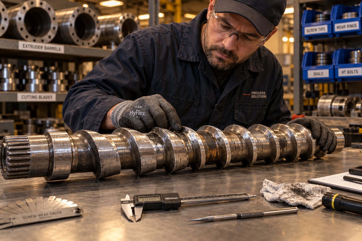
Maintenance, Wear Parts, and Troubleshooting Your Pelletizing Line
A plastic pelletizer machine does not fail suddenly. It drifts. Motor amperage creeps up a few percent per week. Pellet tails appear on Monday but disappear by Wednesday, so nobody logs them. A faint vibration in the gearbox becomes background noise. Then one shift, the cutter jams, the drive faults on overload, and an eight-hour repair wipes out a full day's production. The root cause was not a catastrophic event — it was months of small, unaddressed signals that compounded into a breakdown.
Proactive maintenance transforms that story. A structured schedule — daily checks that take minutes, weekly inspections that take an hour, and deeper quarterly reviews — catches drift before it becomes downtime. The payoff is measurable: higher uptime, consistent pellet quality, and wear parts that reach their full service life instead of failing prematurely.
Preventive Maintenance Schedules
Think of maintenance as a tiered system. Each tier catches a different class of problem, and skipping any one of them leaves a gap that the next tier was never designed to cover.
Daily — the 15-minute pre-shift sweep. Before startup, walk the line from hopper to bagging station. Check cooling water flow and temperature. Inspect the strand guide or die-face area for residual buildup. Confirm that feed hoppers are clear of bridging. Verify that all safety guards are in place and emergency stops are functional. After shutdown, clean the die face, clear any accumulated fines from the cutter housing, and drain water from cooling troughs or centrifugal dryers to prevent overnight stagnation. These tasks require no special tools and take a single operator roughly 15 minutes — yet they prevent the majority of nuisance stoppages that erode shift output.
Weekly — hands-on tuning. Once a week, go deeper. Inspect cutter blades for chipping, rounding, or uneven wear patterns. Measure the knife-to-die gap with feeler gauges and compare it to your baseline setting — even a 0.02 mm drift can produce tails on sensitive materials. Check belt tensions on drives and conveyors. Verify thermocouple readings against a calibrated reference to ensure barrel zone temperatures have not drifted. Inspect screen changer seals for leakage, and examine the melt filter for signs of polymer bleed-through that indicate a damaged screen. Lubricate all grease points per the manufacturer's schedule.
Monthly and quarterly — deep system health. Monthly tasks include gearbox oil level and condition checks, motor insulation resistance testing, alignment verification between the extruder drive and gearbox, and a thorough inspection of the cooling circuit for scale buildup. Quarterly reviews should cover a full cutter rebuild — replacing bearings, resetting all blade clearances, and checking rotor runout. Descale heat exchangers and cooling towers. Calibrate gravimetric feeders and loss-in-weight controllers against known test weights. Structured maintenance checklists that document each task, its completion date, and any abnormal findings turn these inspections into a living record you can mine for patterns over time.
Annual — major overhaul. Once a year, schedule a planned shutdown long enough to pull the screw for measurement, bore-gauge the barrel for wear, service the gearbox internals, replace all seals and gaskets on hydraulic systems, and perform a full electrical inspection including contactor condition and cable termination torque. This is also the time to reassess barrel alignment — especially on long-barrel extruders where thermal cycling and foundation settlement can introduce subtle bowing that accelerates uneven wear.
Critical Wear Parts and Replacement Timing
Every pelletiser has components that are designed to wear. The question is never whether they will need replacement, but when — and whether you replace them on your schedule or on the machine's.
Screw elements and barrels endure the harshest service in any pelletizing system. The screw flights shear against the barrel wall through millions of rotations, and the polymer melt between them often carries abrasive fillers, mineral dust, or glass fibers that act like liquid sandpaper. As extrusion wear research has documented, flight clearance increases progressively with service hours. When that clearance grows to roughly four times the original specification, specific rate drops, discharge temperature rises, and the operator must reduce throughput to maintain product quality — a silent profitability drain that costs far more than the replacement part.
For single-screw systems, the guideline is straightforward: the flight clearance when new is approximately the nominal screw diameter divided by 1,000 per side. A 100 mm screw, for example, starts life with roughly 0.10 mm clearance per side. When that doubles to 0.20 mm, the extruder is compensating with higher screw speed and hotter discharge. By the time it reaches four times the original clearance, replacement or reconditioning is economically unavoidable. Keep a spare screw on the shelf so the swap takes hours, not days — and note that a screw should generally not be refurbished more than three times before the base metal degrades to the point where hard-facing delaminates.
For twin-screw extruders, the modular design means you replace individual screw elements and barrel segments rather than the entire assembly. Kneading blocks and high-shear mixing zones wear fastest, especially when processing filled or abrasive compounds. Suppliers specializing in twin-screw wear components — such as NANHAIYA, which engineers custom parallel twin screw barrels for compounding, recycling, and masterbatch applications — offer bimetallic barrel liners and hardened screw elements that extend service intervals significantly in abrasive and corrosive environments. Sourcing barrels from a specialist who understands the specific wear profile of your material pays back through longer replacement cycles and more consistent melt quality between change-outs.
Iron-based bimetallic barrel liners typically last about three times the service life of a screw. The finished liner thickness is approximately 1.5 mm (0.060 in.), and once that liner is worn through to the base steel, barrel replacement is mandatory. Bore-gauging during annual overhauls tracks the wear rate and lets you predict replacement timing months in advance.
Die plates wear at the orifice edges, causing holes to enlarge and lose their round profile. Oversized holes produce thicker strands, heavier pellets, and — in die-face systems — poor pellet shape. Inspect die plates monthly for erosion, especially when running filled compounds. Reconditioning by re-lapping the die face extends life, but eventually the holes drift out of tolerance and the plate must be replaced.
Cutting blades are the fastest-wearing component on most lines. For clean LDPE and HDPE, blades may last several weeks before needing resharpening. For abrasive materials like glass-fiber-filled PA, weekly inspection and rotation are common. The key indicator is pellet quality: the moment you see an increase in tails, fines, or uneven length, the blades need attention. Always realign to the die face immediately after a blade change — a fresh blade in a drifted setting still produces defects.
Screen changer screens are consumables by design. Replacement frequency depends entirely on feedstock contamination. Post-industrial regrind may go days between screen changes; heavily contaminated post-consumer waste can load a screen in hours. Track melt pressure upstream of the screen pack — a rising trend is your advance warning.
Bearings in the gearbox, cutter rotor, and roll assemblies fail through fatigue, contamination, or inadequate lubrication. Monitor vibration levels and bearing temperatures weekly. A sudden spike in either metric warrants immediate investigation before a bearing seizure damages the shaft or housing.
Troubleshooting Common Operational Problems
Even with perfect maintenance, operational problems happen. Feed quality changes, ambient conditions shift, or a parameter drifts between inspections. When something goes wrong during a production run, you need a fast, systematic diagnosis — not a guessing game. The table below maps the most common pelletizer problems to their symptoms, probable causes, and corrective actions. Keep it accessible on the plant floor.
| Problem | Symptoms | Probable Causes | Corrective Actions |
|---|---|---|---|
| Surging Output | Fluctuating melt pressure; inconsistent pellet size and weight; strand diameter pulsing visibly | Inconsistent feed rate (bridging, starve feeding); worn screw with excessive flight clearance; incorrect temperature profile causing partial melting | Install or recalibrate gravimetric feeder; measure screw wear and replace if clearance exceeds 2x original; adjust barrel zone temperatures to ensure complete melting before the metering section |
| Motor Overload | Drive trips on overcurrent; high torque alarm; motor temperature rising above baseline | Cold startup with solidified material in barrel; feed rate exceeding screw conveying capacity; foreign object lodged in screw channel; excessive backpressure from clogged screen | Ensure barrel reaches full operating temperature before introducing feed; reduce feed rate; inspect and clear barrel; change screen pack and monitor pressure trend |
| Die Drool | Waxy or degraded polymer oozing from die face around orifices; buildup on die lip that periodically breaks off into pellets | Low-molecular-weight fractions or additives migrating to the die surface; die temperature too low causing condensation; poor die-lip finish from wear or damage | Raise die temperature slightly; polish or re-lap die face; review additive package for volatile or low-MW components; ensure adequate melt filtration upstream |
| Inconsistent Pellet Size | Mixed pellet lengths in the same batch; weight variation exceeds specification; downstream feeder dosing errors | Plugged die holes reducing active strand count; cutter speed not synchronized with strand take-up; blade misalignment or uneven wear; melt temperature variation across the die | Clean or replace die plate; recalculate and set cutter-to-haul-off speed ratio; realign and inspect blades; balance die heater zones for uniform melt flow |
| Excessive Fines | Dust accumulation in cutter housing and pneumatic conveying lines; pellet batch fails bulk density spec; conveying system blockages | Dull blades fracturing rather than shearing; polymer too brittle at cutting temperature; excessive conveying air velocity shattering pellets during transport | Replace or resharpen blades; raise melt or water-bath temperature to improve pellet ductility; reduce pneumatic conveying velocity and use gentler elbows |
| Strand Breakage (Strand Systems) | Strands snapping at water bath or between die and puller; operator constantly re-threading; high scrap rate | Melt temperature too low for adequate strand tensile strength; moisture flashing in the melt; die holes partially plugged creating uneven strand diameters | Raise die and final barrel zone temperatures within material limits; verify feedstock drying; clean die plate; check for water splashing onto strands near the die exit |
| Die Freeze-Off (Underwater Systems) | Die holes plugging one by one; reduced pellet count; increasing melt pressure | Process water temperature too low chilling the die face; insufficient melt pressure during startup; line speed too low for die thermal balance | Raise process water temperature during startup; use water bypass to pre-heat die face before engaging cutter; increase throughput to maintain die thermal equilibrium |
A practical rule from experienced field engineers: if the same problem returns within one shift after you clear it, the root cause is upstream of the point where the symptom appeared — feed instability, melt quality, or screen condition. If it returns after weeks of clean running, the cause is wear or gradual drift in blade condition, gap setting, or barrel clearance. Treating these two failure modes differently saves enormous diagnostic time.
Documentation ties everything together. When operators record each stoppage — the symptom observed, the melt pressure at the time, the blade gap measurement, and the corrective action taken — the line builds a failure history that reveals patterns no single inspection can. A blade that lasts 40 tons on unfilled PP but only 25 tons on mineral-filled compound tells you exactly when to schedule the next change. A screen that loads in four hours every time you run a specific post-consumer bale tells you that bale needs more upstream washing, not more frequent screen swaps.
Maintenance is not a cost center. It is the mechanism that protects every dollar you invested in equipment, every hour of operator training, and every relationship with a customer who expects consistent pellets on a reliable delivery schedule. Build the discipline — daily, weekly, monthly, annually — and your pelletizing line repays it with years of productive, profitable service.
Frequently Asked Questions About Plastic Pelletizing Machines
1. What is a plastic pelletizing machine used for?
A plastic pelletizing machine melts raw or recycled plastic and cuts it into small, uniformly sized granules — typically 3 to 5 mm. These pellets serve as standardized feedstock for injection molding, blown film extrusion, blow molding, and sheet extrusion. In virgin resin compounding, pelletizers blend base polymers with additives and colorants. In recycling operations, they transform washed plastic flakes or regrind into sellable recycled pellets that re-enter the manufacturing supply chain, turning low-value waste into a marketable commodity.
2. What are the main types of pelletizing systems and how do they differ?
The four primary pelletizing systems are strand, water-ring, underwater, and hot-face air-cooled. Strand pelletizing cools molten strands in a water bath before cutting them into cylindrical pellets — it is the lowest-cost option and easiest to clean between jobs. Water-ring systems cut at the die face and quench pellets in a spinning water ring, producing rounded tablet-shaped granules in a compact footprint. Underwater pelletizers flood the cutting chamber with process water, creating near-perfect spheres at the highest throughput rates. Hot-face air-cooled systems use forced air instead of water, making them ideal for moisture-sensitive materials like PVC and biodegradable resins.
3. How do I choose between a single-screw and twin-screw extruder for pelletizing?
Single-screw extruders work well for straightforward recycling of clean, pre-sorted single-polymer streams such as HDPE regrind or PP offcuts. They cost less and require simpler maintenance. Twin-screw extruders are preferred when the application demands intensive mixing — for example, dispersing pigments in masterbatch, incorporating glass fibers or mineral fillers, blending multiple resins with compatibilizers, or running reactive extrusion. Their modular barrel and screw design, available from specialists like NANHAIYA, allows processors to configure shear profiles for specific material challenges. Many operations start with a single-screw line and add twin-screw capability as they move into higher-value compounding work.
4. What are the most common pellet defects and how can they be fixed?
Common pellet defects include tails and angel hair (thin whiskers caused by dull blades or excessive blade-to-die gap), voids and bubbles (from residual moisture or poor vacuum degassing), discoloration (thermal degradation or carbonized buildup), and inconsistent pellet size (from plugged die holes or extruder output surging). Prevention centers on four practices: thorough feedstock drying, maintaining sharp cutter blades on a scheduled rotation, holding stable extruder temperature profiles with calibrated thermocouples, and proactive screen changes based on melt pressure trends rather than calendar intervals.
5. How much does it cost to operate a plastic pelletizing line?
Operating costs extend well beyond the equipment purchase price. Electricity typically accounts for 45% to 55% of monthly expenses, with specific energy consumption ranging from 0.3 to 0.5 kWh per kilogram for clean feedstock. Labor represents 20% to 30%, depending on automation level and feedstock contamination. Wear parts, yield losses, depreciation, cooling water, and facility overhead make up the remainder. Well-optimized mid-size pelletizing lines generally achieve payback within 18 to 36 months. Running the line above 80% utilization is the single biggest lever for shortening that payback period, as it spreads fixed costs across more kilograms of output.
Written by
Nanhaiya Technical Team
Zhoushan Nanhaiya Plastic Machinery Co., Ltd.
The Nanhaiya technical team supports screw and barrel manufacturing projects through application review, technical communication, custom manufacturing coordination, and production and quality control.
Discuss Your Application
Related Articles
More insights on screw barrel technology and plastics processing.
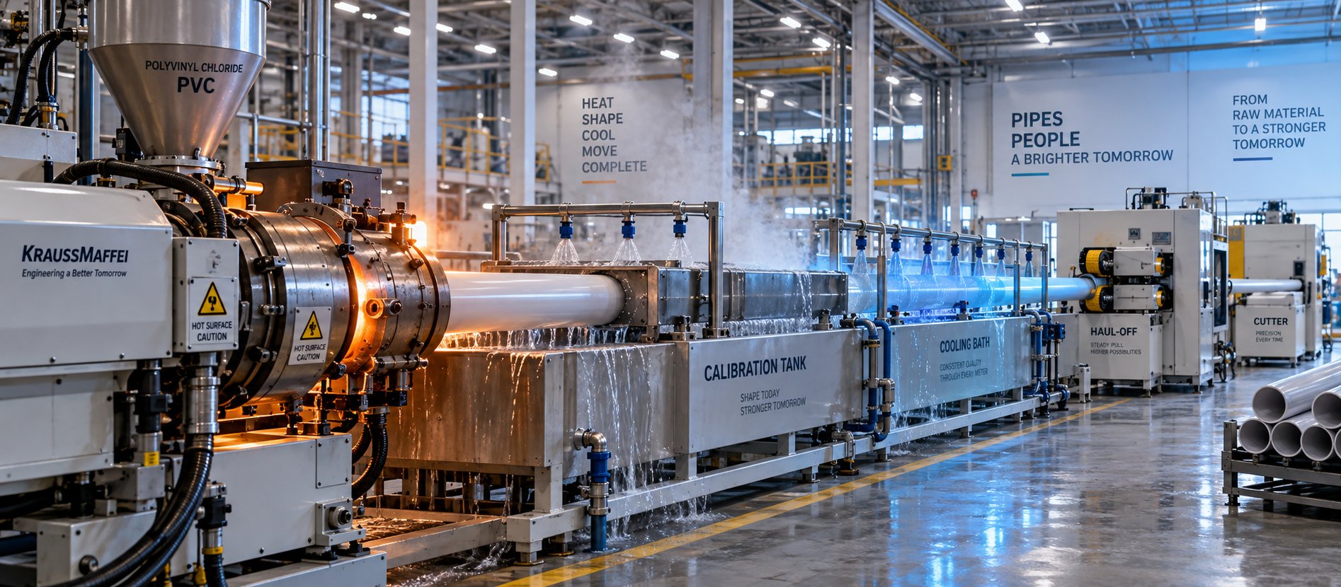
PVC Pipe Making Machine: What No Supplier Will Tell You First
Oct 21, 2026
Learn what a PVC pipe making machine really includes, how each component works, extruder types compared, maintenance schedules, defect fixes, and buying tips.
Read Article
What Your Film Extrusion Machine Datasheet Won't Tell You
Oct 20, 2026
Film extrusion machine guide covering blown vs cast processes, multilayer configurations, screw specs, resin selection, and supplier evaluation for production engineers.
Read Article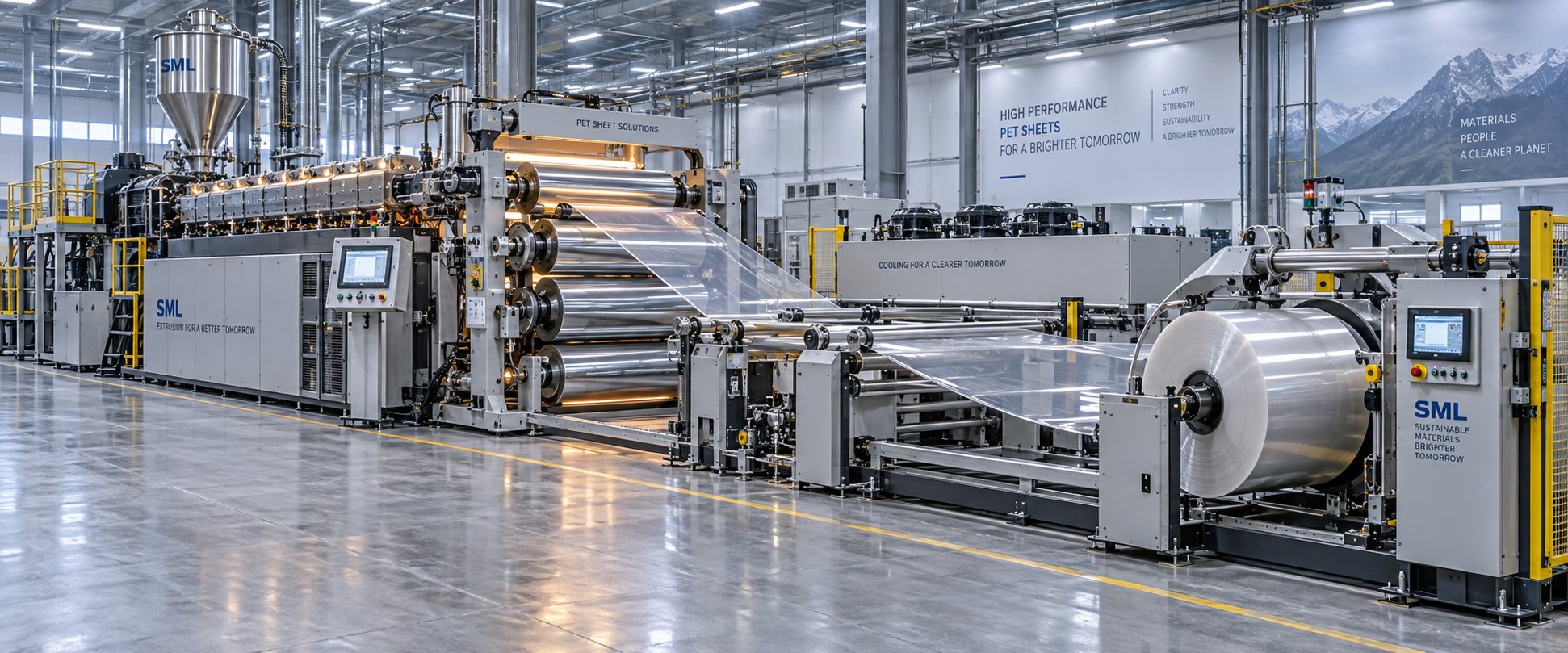
Pet Sheet Extrusion Machine Secrets Your Supplier Won't Share
Oct 15, 2026
Learn how a PET sheet extrusion machine works, key components, specs by production scale, troubleshooting defects, and buyer tips your supplier won't share.
Read ArticleLooking for something else?
Search by material, symptom or product and jump straight to the relevant page.
These are navigation suggestions based on keyword matching — not a quotation, not a delivery commitment, and not a substitute for engineering review. Final specification is confirmed by our engineers against your drawings and processed material.
Need help with screw barrel selection?
Share your machine model, processed material and application. Our team can help with pricing and technical support.