

What a Gearbox for Twin Screw Extruder Actually Does
Imagine a single electric motor spinning at 1,500 RPM. Your twin screws need to turn at maybe 300 RPM — and they need far more rotational force than that motor alone can deliver. Oh, and there are two screws, not one, each demanding exactly the same torque at exactly the same instant. That is the job description for one of the most specialized components in polymer processing.
Defining the Twin Screw Extruder Gearbox
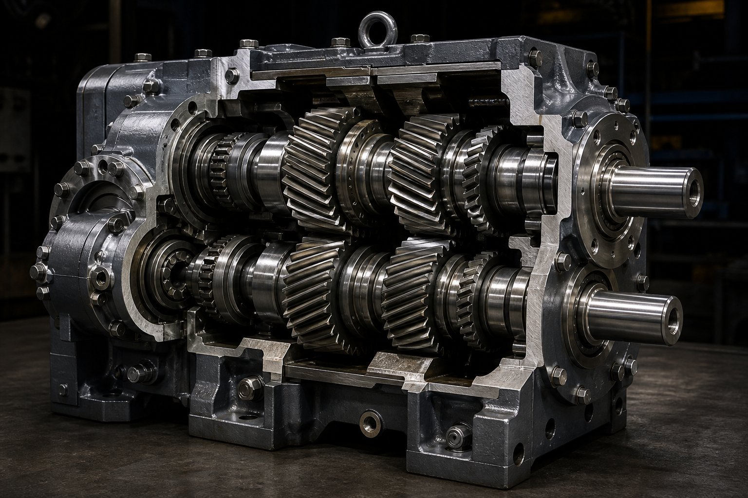
A gearbox for twin screw extruder is a precision power transmission unit that accepts rotational energy from a single drive motor, reduces its speed, multiplies its torque, and splits that torque equally between two closely spaced, synchronized output shafts. These two shafts connect directly to the extruder screws, driving them at the precise speeds and forces required for compounding, reactive extrusion, devolatilization, or any other twin screw process. Without this component, the screws simply cannot rotate under the conditions the application demands.
What sets a twin screw extruder gearbox apart from every other industrial gearbox? It performs three functions simultaneously: speed reduction, torque multiplication, and torque distribution. A standard industrial reducer handles the first two. A twin screw gearbox for extruder applications must also divide power into two perfectly balanced streams — a task that introduces engineering challenges found nowhere else in power transmission.
Contrast this with a single screw extruder gearbox. That unit drives one output shaft. It needs robust bearings and adequate torque capacity, yes, but its designers never wrestle with fitting two high-torque gear trains into a housing barely wider than a dinner plate. The twin screw variant, on the other hand, must pack all of that capability into a package constrained by the tight spacing between the two screws — a distance often measured in just a few tens of millimeters.
Why This Gearbox Is Uniquely Complex
The real engineering difficulty comes down to one physical constraint: center distance. Twin extruder screws mesh with each other, so their shaft centerlines sit extremely close together. The gearbox output shafts must match that same tight spacing. Yet the gears and bearings needed to transmit high torque physically demand more room than that center distance provides. This creates a design puzzle that has driven decades of innovation in gear train layout, bearing selection, and housing architecture.
The stakes are high. Twin screw gearboxes must maintain precise angular timing between the two output shafts — any timing error under load causes the screws to interfere, potentially damaging both the screws and the gearbox internals. Modern high-performance units deliver torque densities reaching 18 Nm/cm³, pushing materials science and gear design to their practical limits.
The gearbox is typically the most expensive single component in a twin screw extruder, and its torque capacity often defines the upper processing limit of the entire line.
This article serves as a vendor-neutral engineering resource. Whether you are a maintenance engineer diagnosing a vibration issue, a plant buyer evaluating specifications, or a machine rebuilder sourcing replacement components, the sections ahead break down how these gearboxes work internally, what fails and why, and how to keep them running at peak performance. The first critical concept to grasp is the center distance constraint — and how it shapes every design decision inside the housing.
The Center Distance Challenge in Twin Screw Extruder Gearbox Design
Here is the paradox every twin screw extruder gearbox designer faces: you need to push enormous torque through two output shafts, but those shafts sit so close together that there is barely enough physical room for the gears and bearings required to carry that load. This single geometric constraint — center distance — shapes every decision inside the housing, from gear tooth profile to bearing type to the number of reduction stages. It is the reason a gearbox for twin screw extruder costs several times more than a comparable single-shaft reducer, and it is the reason so many creative engineering solutions have emerged over the past five decades.
The Center Distance Constraint Explained
Picture two twin screws inside an extruder barrel. They intermesh — meaning the flight of one screw reaches into the channel of the other. For that intermeshing to work, the centerlines of the two screws must sit at a fixed distance apart, determined primarily by the screw outer diameter. On a typical 50 mm twin screw extruder, the center distance between shaft axes might be around 42 mm. On a large 120 mm machine, you might see roughly 100 to 106 mm. Either way, the space is tight relative to the forces involved.
The gearbox output shafts must match this exact center distance, because they couple directly to the screw shafts. And here is where the trouble begins. To transmit, say, 500 Nm of torque per shaft, you need gears with a certain minimum tooth size, root diameter, and face width. You also need bearings with adequate load ratings — and bearings take up radial space. When the center distance only gives you a few tens of millimeters between shaft axes, there simply is not enough room to fit full-sized gears and robust bearings side by side.
Imagine trying to park two trucks in a single-car garage. The trucks represent the torque-carrying capacity you need; the garage is the center distance you have. Something has to give — or you need a completely different approach to arranging the machinery.
Increasing screw diameter does relax this constraint somewhat. A 90 mm screw set has a wider center distance than a 35 mm set, giving designers more room for gears and bearings. But larger screws also process more material at higher throughputs, which demands proportionally more torque per shaft. The available space grows, yet the torque requirement grows faster. The fundamental tension between space and power never truly disappears.
How Designers Overcome the Space Limitation
Since you cannot simply enlarge the gearbox output section beyond what the screw center distance allows, designers attack the problem through multi-stage gear arrangements and intermediate distribution shafts. The core idea is to move the heavy torque-carrying work away from the cramped output zone and spread it across shafts that have more room.
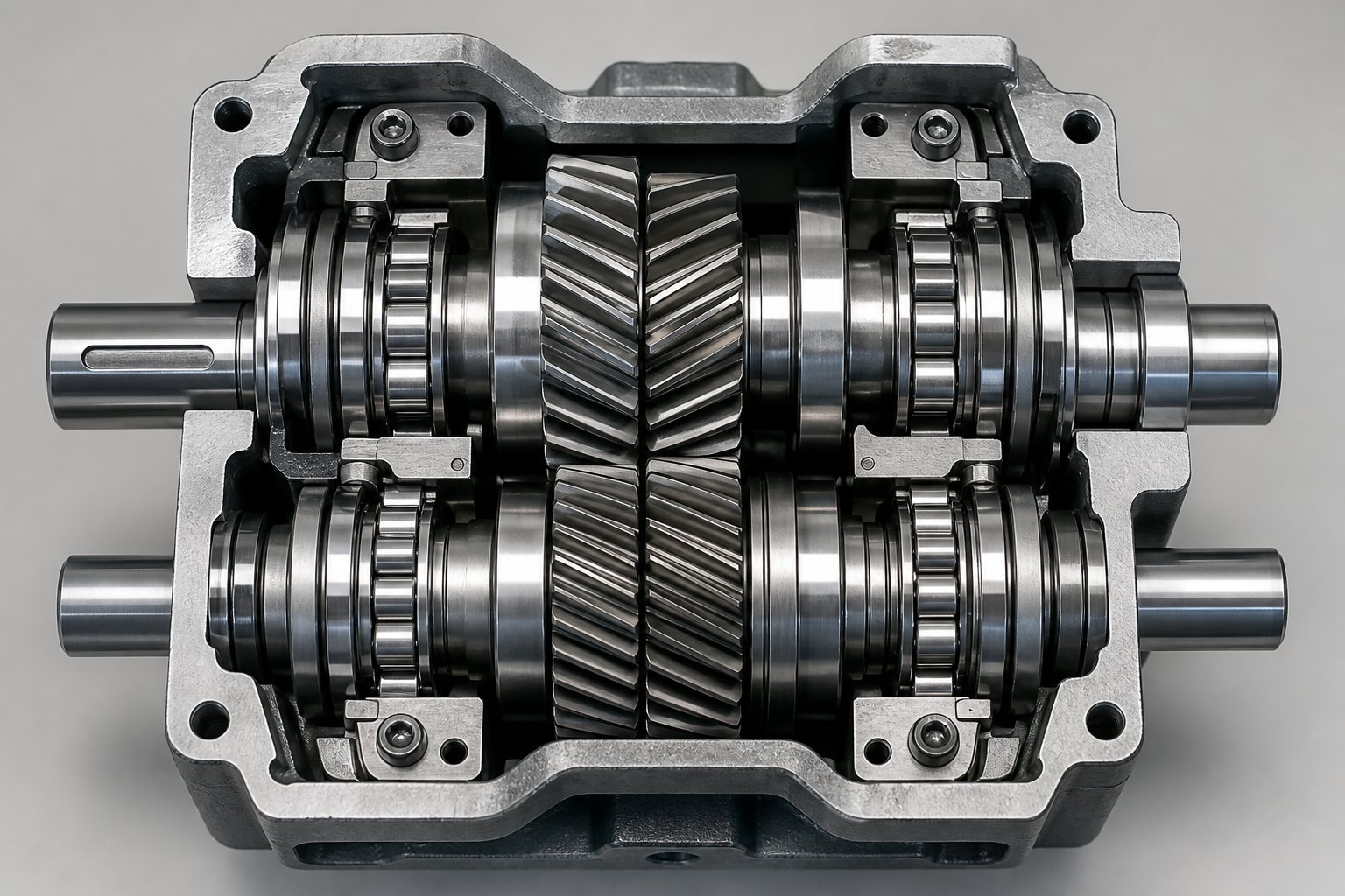
In a typical twin screw extruder gearbox design, the power path flows through two or three reduction stages using helical or herringbone gear pairs before it reaches the distribution stage. At the distribution stage, a single gear on one output shaft meshes with gears on two parallel intermediate shafts — called distributor shafts — which then drive the second output shaft from both sides simultaneously. This bilateral distributor shaft concept, well documented in patent literature, splits the load so that each gear mesh only handles a fraction of the total torque rather than the full amount.
Why does this matter so much? Consider a parallel three-axis gear structure, one of the simplest layouts for a gearbox parallel twin screw extruder. In this arrangement, power flows in parallel to two output shafts, but the second shaft (often called the B-axis) is squeezed into the tight center-distance zone. Its gears are physically smaller, making it the weak link. As described in engineering references from industry sources, the B-axis bearing in this layout endures constant unidirectional radial loading, accelerating wear and limiting overall gearbox life to around 20,000 hours before bearing replacement becomes necessary.
The double-sided symmetrical drive structure solves this elegantly. By splitting power into upper and lower gear sets that drive the B-axis from opposite directions, the radial forces on that shaft cancel each other out. The result is a pure torque couple — the B-axis bearing sees virtually no radial load, extending theoretical service life to 72,000 hours or more. This twin parallel screw extruder gearbox architecture also doubles the effective torque capacity within the same center-distance envelope, because each gear mesh only carries 25% of total torque instead of 50%.
A German patent for high-power twin-screw extruder gearboxes takes this further by describing bilateral distributor shafts arranged on both sides of the driven output shaft, ensuring symmetric load sharing. The patent notes explicitly that the small center distance of the two output shafts demands power branching — each tooth engagement only needs to be sized for a quarter of total power, making the geometry feasible even under extreme loads exceeding 10,000 kW.
Every one of these solutions involves trade-offs. Here are the key design tensions engineers must balance:
- Compactness vs. torque capacity — Smaller gear diameters fit the center distance but reduce the amount of torque each tooth can safely carry, pushing designers toward more reduction stages or power-split architectures.
- Bearing life vs. center distance — Larger bearings last longer under load, but they consume radial space that the tight shaft spacing cannot spare. Bilateral designs mitigate this by reducing or eliminating radial bearing loads entirely.
- Gear tooth strength vs. available gear diameter — Wider face widths or finer pitch teeth can compensate for small gear diameters, but both approaches add manufacturing complexity and cost.
- Number of gear stages vs. efficiency — Each additional stage introduces mesh losses, typically 1-2% per stage, which accumulate into heat generation and reduced overall drive efficiency.
- Manufacturing precision vs. cost — Double-sided symmetrical structures demand extremely tight machining tolerances to ensure equal load sharing, raising production expense significantly over simpler layouts.
These trade-offs explain why the gearbox remains one of the most intensively engineered — and most expensive — subsystems in any twin screw extrusion line. The center distance constraint is permanent and non-negotiable, set entirely by the screw geometry. Every improvement in torque density, bearing life, or processing capability must be won within that fixed, unforgiving envelope.
The physical layout of the gear train, however, is only half the story. Equally critical is what happens at the distribution stage itself — the mechanism that takes a single stream of rotational power and divides it into two perfectly equal outputs, ensuring both screws see identical torque at every instant.
How Torque Splitting Works Inside the Gearbox
A single motor, two screws, and one absolute requirement: each screw must receive exactly the same rotational force at every moment. That is the essence of twin screw extruder gearbox torque splitting, and it is the function that separates this type of gearbox from every other power transmission unit in industrial service. Understanding how a twin screw extruder gearbox works — step by step, from motor input to synchronized output shafts — reveals why precision in this mechanism is non-negotiable.
From Motor to Two Shafts — The Power Path
Think of the power path inside a gearbox for twin screw extruder as a river that starts as a single fast-flowing stream, slows down, gains depth, and then divides into two perfectly equal channels. Each stage has a specific mechanical purpose, and skipping or misunderstanding any one of them leads to trouble downstream.
Here is how rotational energy travels from the motor coupling to the extruder screws:
- Motor input shaft — The drive motor connects to the gearbox through a coupling, delivering high-speed, relatively low-torque rotational energy. A typical AC motor might spin at 1,000 to 1,800 RPM, depending on pole count and frequency drive settings.
- First reduction stage — A helical or herringbone gear pair reduces the input speed and proportionally increases the torque. For example, a 3:1 reduction at this stage cuts speed to roughly one-third while tripling the available torque. Herringbone gears are often preferred here because their opposing tooth angles cancel axial thrust forces generated within the gear mesh itself.
- Second reduction stage (if present) — Many twin screw extruder gearboxes and motors use two or even three reduction stages in series to achieve the total ratio needed. Each additional stage multiplies torque further while reducing speed. A two-stage gearbox with ratios of 3:1 and 4:1 delivers an overall 12:1 reduction — transforming 1,500 RPM input into 125 RPM output while multiplying torque twelvefold.
- Distribution stage — This is the defining stage. A single distribution gear, mounted on an intermediate shaft, meshes simultaneously with two output gears — one on each output shaft. The geometry is arranged so that both output gears are identical in size and tooth count, and the distribution gear contacts both under symmetric conditions. The torque arriving from the reduction stages divides equally: 50% flows to the left output shaft, 50% to the right.
- Synchronized output shafts — The two output shafts exit the gearbox housing at the exact center distance required by the extruder screws. They rotate at the same speed, in the same direction (for co-rotating machines) or opposite directions (for counter-rotating machines), each carrying precisely half the total torque.
The bilateral distribution concept — positioning the distribution gear centrally between both output gears — ensures that the load path is geometrically symmetric. Patent literature from A. Friedr. Flender AG describes arrangements where bilateral distributor shafts engage both output gears from opposing sides, guaranteeing equal power transfer regardless of load fluctuation. This symmetry is not merely desirable; it is structurally essential.
Why Equal Torque Distribution Matters
What happens if one output shaft gets 55% of the torque while the other receives only 45%? The consequences cascade quickly through the entire extrusion line.
The overloaded screw deflects slightly toward the barrel wall under the extra torsional force. Even a few thousandths of a millimeter of deflection accelerates metal-to-metal contact between screw flights and barrel bore, wearing both surfaces unevenly. On the underloaded side, the screw processes material at a lower energy input, producing a slightly different melt temperature and viscosity profile. The result is inconsistent melt quality — visible as variations in pellet size during compounding, surface defects in profile extrusion, or uneven additive dispersion in masterbatch production.
Over time, the imbalance compounds. Premature barrel wear on one side increases clearance, reducing pumping efficiency and creating a feedback loop that further degrades output quality. The overloaded gearbox bearings on the high-torque shaft deteriorate faster, raising vibration levels and generating metallic wear particles that contaminate the lubricant. What began as a subtle torque imbalance eventually manifests as an unplanned shutdown and a costly rebuild.
This is precisely why gearbox manufacturers invest heavily in gear grinding accuracy, bearing preload consistency, and symmetric housing designs. Even small manufacturing deviations in gear tooth profile or bearing clearance can skew the torque split. High-quality twin screw extruder gearboxes hold the torque balance within 1-2% across the full operating speed range — a tolerance that demands exceptional precision in both fabrication and assembly.
Axial Thrust Bearing Systems
Torque is not the only force a twin screw extruder gearbox must handle. There is another load that engineers sometimes underestimate — and it can be the one that kills the gearbox first.
As the screws push polymer melt forward against die resistance, a reaction force pushes the screws backward — directly into the gearbox. This axial thrust load can be enormous. In twin screw extruders, back pressure forces range from 2.5 kN on small laboratory machines to 3,400 kN on large production units. On many extruder lines, the axial load actually exceeds the torsional load in engineering significance, meaning the twin screw extruder gearbox thrust bearing system — not the gear teeth — defines the service life ceiling.
Thrust bearings inside the gearbox absorb this rearward push. Most designs use stacked arrangements of angular contact ball bearings or tapered roller bearings on each output shaft, configured to handle loads in the axial direction while allowing free rotation. The theoretical calculation life of these thrust bearings typically targets around 12,000 hours under rated operating conditions. Exceeding the rated axial load — by running at excessive die pressures or processing highly viscous materials — shortens this life dramatically.
Gear accuracy also plays a hidden role here. Higher gear accuracy classes ensure that thrust loads distribute evenly across the bearing contact surfaces rather than concentrating on a small area. Poor gear quality creates uneven load distribution, which fatigues bearing raceways prematurely even when the total axial force stays within the rated envelope.
Thrust bearing capacity often limits gearbox life before torque capacity does. An undersized thrust bearing fails through fatigue even when the gear train handles the torque without issue.
When specifying or evaluating a gearbox for twin screw extruder service, engineers should treat the axial load rating as seriously as the torque rating. Both numbers must match the extruder's actual operating conditions — and both must include adequate safety margin for startup surges, material changes, and die pressure variations. The interplay between torque capacity and thrust capacity is one of the most commonly overlooked aspects of gearbox selection, yet it directly determines whether the unit delivers years of reliable service or fails prematurely from bearing fatigue.
Torque splitting and thrust management define what happens inside the housing. The next layer of complexity involves the different architectural layouts required for co-rotating, counter-rotating, and conical screw configurations — each of which reshapes the internal gear arrangement to match a fundamentally different shaft geometry.
Types of Twin Screw Extruder Gearboxes Compared
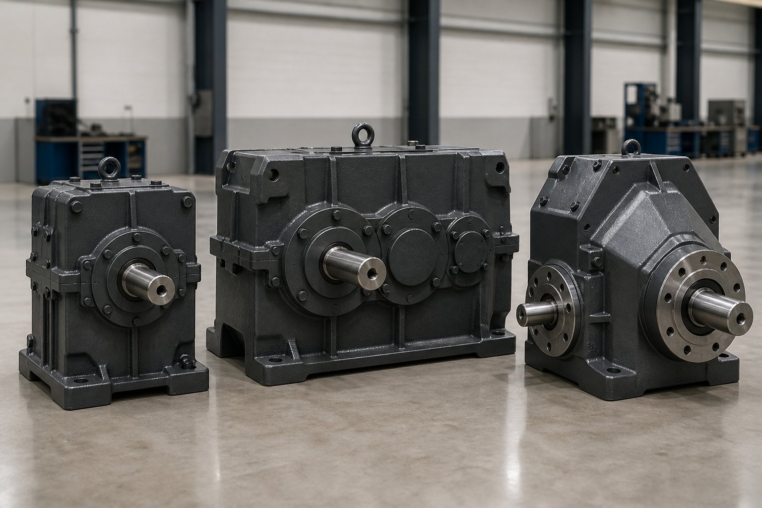
Not every twin screw extruder spins its screws the same way — and that single difference reshapes the entire gearbox interior. The screw configuration you choose (co-rotating or counter-rotating, parallel or conical) dictates the gear train layout, the bearing arrangement, and the severity of the center distance challenge. Selecting the wrong gearbox architecture for your screw type is not just an engineering mismatch; it is a recipe for premature failure and lost throughput.
Co-Rotating Parallel Gearbox Architecture
A co-rotating twin screw extruder gearbox drives both output shafts in the same rotational direction at identical speed. How does the gear train achieve this? The distribution gear meshes with two output gears arranged so that both rotate in the same direction — typically through an intermediate idler gear or a symmetric gear path that preserves rotational sense on both shafts.
This is the dominant architecture in polymer compounding, masterbatch production, and reactive extrusion, where intermeshing co-rotating screws deliver excellent mixing efficiency through a characteristic spiral "figure-eight" flow pattern. The processing demands are intense: high screw speeds (often 300 to 1,200 RPM), high fill levels, and viscous melts all combine to push torque requirements to their practical ceiling. As a result, this type demands the highest torque density of any twin screw plastic extruder gearbox — meaning the most torque per cubic centimeter of gearbox volume.
You will find co-rotating parallel gearboxes on machines ranging from small 16 mm laboratory extruders up to 180 mm production units. In every case, the tight center distance constraint is at its most severe here, because parallel co-rotating screws require the closest shaft spacing relative to their diameter.
Counter-Rotating Parallel Gearbox Architecture
Flip the rotation of one shaft, and the internal gear arrangement changes significantly. A counter-rotating gearbox drives the two output shafts in opposite directions. Mechanically, this is simpler in one respect — a single distribution gear meshing with two output gears naturally produces opposite rotation without additional idler stages.
Counter-rotating parallel extruders excel in applications requiring strong positive-displacement conveying and gentle shear. PVC pipe extrusion, profile extrusion, and sheet production are the classic use cases. Screw speeds tend to be lower (5 to 50 RPM in many PVC applications), and the materials processed are often heat-sensitive, requiring careful energy management. The gearbox torque density demand is lower compared to high-speed co-rotating units, but the thrust loads can be substantial due to high die pressures in pipe and profile tooling.
Because the screws rotate toward each other at the top (or away from each other, depending on the configuration), the meshing geometry creates a C-shaped flow chamber that acts as a positive pump. This changes how the gearbox must manage load transients — pressure pulses from the calendering zone travel back through the screws and into the gearbox bearings as cyclic axial and radial loads.
Conical Twin Screw Gearbox Design
Imagine spreading the two screw shafts apart at the feed end while bringing them closer at the discharge end. That is a conical twin screw extruder gearbox in concept — the output shafts are not parallel but converge at an angle, typically between 5 and 8 degrees.
This geometry fundamentally changes the center distance challenge. At the feed end, where the screws have their largest diameter, the shaft spacing is wide. That extra room allows designers to install larger, more robust bearings and bigger gears — a luxury parallel gearbox engineers rarely enjoy. The torque transmission challenge eases considerably compared to parallel architectures of similar screw diameter.
Conical twin screw extruders are most common in PVC processing, particularly for window profiles, siding, and foam board. They typically operate counter-rotating and at low to moderate speeds. A conical twin screw extruder gearbox must accommodate the angular shaft orientation with bevel or hypoid gear stages, adding complexity to the gear train but relaxing the space constraints that make parallel gearboxes so difficult to engineer.
| Feature | Co-Rotating Parallel | Counter-Rotating Parallel | Conical (Counter-Rotating) |
|---|---|---|---|
| Rotation Direction | Same direction | Opposite directions | Opposite directions |
| Typical Screw Diameter Range | 16 mm to 180 mm | 35 mm to 130 mm | 35/70 mm to 80/156 mm (small/large end) |
| Primary Applications | Compounding, masterbatch, reactive extrusion | PVC pipe, profile, sheet extrusion | PVC window profiles, siding, foam board |
| Relative Torque Density Demand | Highest | Moderate | Lower |
| Center Distance Challenge Severity | Most severe | Severe | Relaxed (wider spacing at feed end) |
Each of these architectures exists because the screw geometry demands it — not because one design is inherently superior to another. The gearbox serves the process, and the process defines the screw configuration. What ties all three types together, however, is a shared dependency: the gearbox specifications must precisely match the screw set's dimensions, speed requirements, and torque demands. Getting that match right is where many engineers stumble, and it starts with understanding exactly how screw geometry drives gearbox sizing.
How Screw Geometry Drives Gearbox Specifications
A gearbox does not exist in isolation. Every dimension, every load rating, and every speed limit on its specification sheet traces back to one source: the twin screws it drives. Change the screw diameter by 10 mm, and the gearbox output shaft spacing must change with it. Push the L/D ratio from 36:1 to 48:1, and the thrust bearings face a heavier axial burden. Increase maximum screw speed from 600 RPM to 1,200 RPM, and the reduction ratio — along with the motor pairing — shifts entirely. The gearbox and the screw set are mechanically married, and mismatching them is one of the costliest errors an engineer can make.
Screw Diameter and Center Distance Matching
Screw outer diameter (OD) is the single parameter that anchors every gearbox sizing decision. Why? Because OD determines the center distance between the two screw axes — and the gearbox output shafts must replicate that center distance exactly, down to hundredths of a millimeter.
For a standard co-rotating, double-flighted (bi-lobal) screw profile, the geometric relationship locks center distance to outer diameter through a fixed constraint. As detailed in twin screw extruder specification guides, the centerline distance (A) must be at least 0.707 times the outer diameter (Do) for the self-wiping profile to function. The inner diameter (Di) follows from the equation Di = 2A - Do. Once you fix the outer diameter and center distance, the channel depth and Do/Di ratio are no longer free choices — geometry locks them.
What does this mean for gearbox specifications? Consider two extruders:
- A 40 mm screw set has a center distance of roughly 32 to 34 mm. The gearbox output shafts must sit at that exact spacing, and all internal gears and bearings must fit within the constraints that spacing imposes.
- A 92 mm screw set pushes the center distance to approximately 72 to 78 mm. The gearbox housing grows, the gears can be physically larger, and bearing options expand — but the torque demand grows even faster than the available space.
When you replace or upgrade a gearbox, the output shaft center distance is the first number to verify. A mismatch of even a fraction of a millimeter between gearbox output and screw coupling alignment creates shaft deflection, bearing side-loading, and accelerated wear on both the gearbox and the barrel. This is not a dimension you can shim or adjust in the field — it must be manufactured correctly from the start.
How L/D Ratio and Speed Affect Gearbox Loads
Screw diameter sets the spatial envelope. But two other screw parameters — L/D ratio and maximum operating speed — define the forces that envelope must contain.
The L/D ratio (total screw length divided by screw diameter) determines how many processing zones fit along the barrel. Industry-standard L/D ratios typically range from 32:1 to 52:1 for production compounding machines, with some reactive extrusion setups pushing to 60:1 or beyond. Every additional unit of L/D adds barrel length, which means more material in the process section, more frictional drag along the screw flights, and — critically — more forward thrust pushing against the gearbox.
Picture it this way: a longer screw is like a longer conveyor belt pushing material toward the die. The die resists that flow, and the reaction force shoves the entire screw assembly rearward into the gearbox thrust bearings. A 48:1 L/D screw running at high throughput generates substantially more axial thrust than a 32:1 screw of the same diameter under similar conditions. That difference is not trivial — it can determine whether the thrust bearing system lasts 12,000 hours or fails at 6,000.
Maximum screw speed introduces a different type of stress: torsional fatigue. Every revolution of the screw shaft subjects the gearbox output components to cyclic loading. At 300 RPM, the gear teeth and bearings experience 300 load cycles per minute. At 1,200 RPM, that number quadruples. Higher speeds also generate more heat through gear mesh friction, demanding better lubrication and more effective cooling systems inside the housing.
The twin screw extruder gearbox speed ratio — the overall reduction between motor input and screw output — must be chosen to place the most commonly used screw speeds within the motor's peak efficiency range. The fundamental relationship is straightforward: Torque (Nm) = 9,550 x kW / max RPM. A 200 kW motor geared for 600 RPM delivers the same torque as a 400 kW motor geared for 1,200 RPM — roughly 3,183 Nm total across both shafts. If your process rarely exceeds 600 RPM, the larger motor adds cost without adding usable torque.
This means the twin screw extruder gearbox torque rating is not just a function of gear size and bearing capacity — it is inseparable from the speed at which those gears operate. Specifying the gearbox without knowing the target screw speed range is like sizing a bridge without knowing the weight of the traffic.
Understanding Specific Torque as a Performance Metric
When comparing gearboxes across different screw sizes, raw torque numbers are misleading. A gearbox delivering 5,000 Nm on a 90 mm extruder and another delivering 800 Nm on a 35 mm machine may represent the same — or even inverted — level of engineering achievement. The raw number scales with machine size. You need a way to normalize.
That is exactly what specific torque does. Expressed as Md/a³ (torque per shaft divided by the cube of the center distance), this metric strips out the scale variable and exposes the true torque density of the gearbox design. A higher Md/a³ value means the gearbox packs more torque-carrying capability into a given center distance envelope — and that directly translates to processing capability.
Why the cube of center distance? Because the forces and stresses involved in power transmission through closely spaced shafts scale volumetrically. The available space for gears and bearings is a three-dimensional problem, so normalizing by the cube of the governing dimension — center distance — produces a fair comparison across machine sizes.
In practice, specific torque classes separate gearbox generations and capability tiers:
- Standard gearboxes — Md/a³ values in the range of 5 to 8 Nm/cm³. Adequate for unfilled polymers, color concentrates, and low-viscosity blends where torque demands are modest.
- High-torque gearboxes — Md/a³ values from 10 to 13 Nm/cm³. These handle moderate-fill compounding, engineering thermoplastics, and applications where the process regularly loads the drive to 70-80% of capacity.
- Ultra-high-torque gearboxes — Md/a³ values of 15 to 18+ Nm/cm³. Required for heavily filled compounds (40-60% glass fiber or mineral filler), reactive extrusion of high-viscosity melts, and production lines where maximizing throughput per unit of screw diameter drives profitability.
The jump from 10 to 18 Nm/cm³ represents roughly an 80% increase in usable torque within the same center distance. For a plant running glass-filled polyamide, that difference can mean the line either hits its throughput target or runs permanently torque-limited, unable to feed material fast enough to justify the capital investment.
When reviewing twin screw extruder gearbox specifications — whether in a supplier datasheet, a gearbox PDF, or a quotation document — always look for specific torque alongside absolute torque and speed ratings. Absolute numbers tell you what the gearbox delivers. Specific torque tells you how hard the engineering had to work to deliver it — and whether there is room to push the process harder as your formulations evolve.
Matching screw geometry to gearbox specifications is ultimately a systems-engineering task. The screw OD sets the center distance. The L/D ratio and throughput set the axial load. The target speed range sets the reduction ratio. And the material viscosity, filler loading, and process intensity determine the required specific torque class. Get every parameter aligned, and the gearbox runs within its design envelope for tens of thousands of hours. Miss even one, and the weakest link — whether it is a thrust bearing, a gear tooth, or a shaft seal — will announce itself through vibration, overheating, or sudden failure.
Recognizing those early warning signs, and understanding what they mean inside the housing, is the difference between planned maintenance and emergency downtime.
Common Gearbox Failures and Troubleshooting Guide
Vibration spikes at 2 AM. A maintenance technician notices oil pooling under the gearbox housing. The operator reports a faint grinding noise that was not there last week. These are not random events — they are the gearbox telling you exactly what is failing inside, if you know how to listen. Every twin screw extruder gearbox failure mode follows a predictable progression from subtle early symptom to catastrophic breakdown, and catching problems during the early stage is what separates a planned repair from a six-figure emergency.
This section serves as a practical twin screw extruder gearbox troubleshooting reference — organized by failure type, with observable symptoms, root causes, and recommended actions for each.
Bearing Wear and Failure Symptoms
Bearings are the first components to protest when something goes wrong. A twin screw extruder gearbox bearing failure rarely happens overnight. Instead, it develops through stages you can detect weeks or even months before the bearing seizes.
The earliest indicator is usually a change in vibration signature. Healthy bearings produce a smooth, low-amplitude vibration baseline. As raceways develop micro-pitting or rolling elements begin to fatigue, the vibration amplitude increases — particularly at bearing defect frequencies that a trained analyst can identify with accelerometer data. You will also notice elevated temperature at the bearing housing. A bearing running 10 to 15 degrees Celsius above its normal baseline is sending a clear distress signal.
Unusual noise follows. What starts as a faint hum or intermittent clicking progresses to a steady rumble or growl as damage spreads across the raceway surface. By the time the noise is obvious to a passerby on the plant floor, the bearing is likely approaching end-of-life.
What causes bearings to fail prematurely? Three root causes dominate:
- Inadequate lubrication — Either insufficient oil flow, degraded oil that has lost its film-forming properties, or the wrong viscosity grade. Research from Sumitomo Drive Technologies shows that using an unapproved oil viscosity dramatically accelerates ferrous wear generation in gearbox bearings, with iron particle counts exceeding set limits within a single year.
- Overloading beyond rated torque or thrust — Running the extruder above its rated specific torque or die pressure compresses bearing contact zones beyond their fatigue limit, initiating subsurface cracking that propagates outward.
- Contamination — Water ingress, process dust, or metallic wear particles from other components act as abrasive agents inside the bearing contact zone. Even 300 ppm of water contamination reduces bearing life to roughly half of its design expectation.
Thrust bearings deserve special attention. Because they absorb the massive axial loads generated by the screws pushing material forward, they operate under sustained heavy loading that radial bearings do not experience. A degrading thrust bearing often announces itself through increased axial play in the output shafts — detectable as screw "float" during startup or shutdown when process forces are absent.
Gear Tooth Fatigue and Surface Damage
Gear teeth in a twin screw extruder gearbox endure millions of stress cycles per month. Under ideal conditions, the hardened tooth surfaces withstand this loading for tens of thousands of operating hours. When conditions deteriorate, however, the tooth surfaces tell a progressive story of distress.
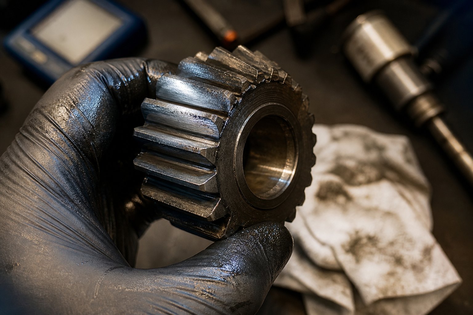
Pitting appears first. Tiny craters form on the tooth contact surface as subsurface fatigue cracks propagate to the surface and release small fragments of metal. Early-stage pitting is sometimes called "initial pitting" and can stabilize if loads remain moderate. But when overloading or poor lubrication persists, pitting deepens and spreads.
Spalling follows. Larger flakes of material break away from the tooth surface, creating irregular craters that disrupt the smooth load-carrying contact zone. Spalling accelerates rapidly — once it starts, the uneven tooth surface concentrates stress at the crater edges, triggering further damage in a self-reinforcing cycle.
Tooth breakage is the final stage. A fatigue crack initiates at the tooth root — the highest-stress region — and propagates until a section of the tooth fractures off completely. A broken tooth sends shock loads through the entire gear train and typically causes immediate, catastrophic gearbox failure requiring a full twin screw extruder gearbox repair or replacement.
The connection to lubrication quality is direct. Oil analysis provides the earliest possible detection window. As gear teeth pit and spall, they release metallic particles into the lubricant. Elemental analysis by ICP (Inductively Coupled Plasma) measures iron content in parts per million, while the Particle Quantifier (PQ) Index measures the total mass of ferrous debris regardless of particle size. A critical diagnostic signal appears when the PQ Index rises sharply while ICP iron values hold steady or decline — this indicates the gearbox is generating large ferrous particles from active gear or bearing surface damage, not just fine wear dust from normal operation.
Catching pitting before it becomes spalling, and spalling before it becomes tooth breakage, is entirely achievable through regular oil sampling and vibration monitoring. Both techniques are inexpensive relative to the cost of an unplanned gearbox failure.
Thermal Degradation and Seal Failures
Heat is the silent accelerator behind most twin screw extruder gearbox failure modes. Every component inside the housing — gears, bearings, seals, and lubricant — has a thermal limit. Exceed it consistently, and degradation compounds on itself.
Lubricant suffers first. The oxidation rate of gear oil approximately doubles for every 10 degrees Celsius increase in operating temperature. Oxidized oil thickens, forms acidic byproducts, and loses its ability to maintain a protective film between metal surfaces. Oxidation testing during oil analysis, reported in absorbance per centimeter (Abs/cm), tracks this degradation over time. When the Acid Number (AN) of used oil climbs above the baseline value established from new oil, degradation has already begun. An AN exceeding 4.0 mg KOH/g indicates the oil is highly corrosive and risks attacking metal surfaces directly.
Shaft seals are equally vulnerable to heat. Standard nitrile or fluoroelastomer lip seals have maximum continuous temperature ratings — typically 100 to 200 degrees Celsius depending on material. Sustained temperatures above these limits harden the seal lip, causing it to lose elasticity and crack. The result is oil leaks at shaft exit points and, more insidiously, contamination ingress. Process dust, polymer fines, or moisture drawn in through a compromised seal accelerate every other failure mode simultaneously.
Visible oil leaks at shaft seals or housing joints are among the most frequently ignored symptoms in the field. Many maintenance teams simply clean up the leak and move on. But an oil leak is a two-way door: contaminants flow in through the same path lubricant flows out. Addressing the seal, not just the puddle, is essential.
Misalignment between the gearbox output shafts and the extruder barrel introduces yet another thermal source. When shaft axes do not align precisely, the coupling and bearings absorb the angular or offset error as heat-generating friction. Thermal expansion during operation can shift alignment from cold-set values by several hundredths of a millimeter — enough to create measurable bearing heating if initial alignment was borderline.
The following table consolidates the most common symptoms, their probable causes, and recommended actions into a quick-reference format suitable for posting near the gearbox on the plant floor:
| Symptom | Probable Cause | Recommended Action |
|---|---|---|
| Excessive vibration | Bearing wear, gear tooth damage, shaft misalignment, or loose mounting bolts | Perform vibration spectrum analysis to isolate source; check bearing clearances; verify gearbox-to-barrel alignment; inspect gear tooth surfaces during next scheduled opening |
| Abnormal noise (grinding, clicking, or rumbling) | Bearing raceway damage, gear tooth pitting or spalling, insufficient lubricant film thickness | Immediately check oil level and condition; collect oil sample for particle analysis; schedule bearing and gear inspection; reduce load if possible until diagnosis is complete |
| High oil temperature | Lubricant degradation (oxidation), overloading, insufficient oil volume, cooling system failure, or misalignment | Verify oil viscosity and condition through oil analysis; check cooling circuit function; review process parameters against rated gearbox capacity; confirm shaft alignment |
| Oil discoloration (darkening or milky appearance) | Oxidation and thermal breakdown (dark oil) or water contamination (milky or cloudy oil) | Submit oil sample for oxidation, Acid Number, and water content testing; replace oil if AN exceeds baseline or water exceeds 300 ppm; identify and eliminate moisture entry point |
| Visible oil leaks at shaft seals or housing joints | Seal hardening from heat exposure, seal lip wear, housing gasket deterioration, or excessive internal pressure from oil foaming | Replace damaged seals with correct material specification; check breather vent for blockage; verify operating temperature stays within seal material rating; inspect housing gasket surfaces |
| Output shaft axial or radial play | Thrust bearing fatigue (axial play) or radial bearing wear (radial play), often from sustained overloading or contamination | Measure play with dial indicator and compare to manufacturer tolerance; plan bearing replacement if play exceeds limits; review process history for overload events; check oil for metallic debris |
Every entry in that table traces back to the same principle: twin screw extruder gearbox failure modes are progressive, not sudden. Bearings pit before they seize. Gears pit before they spall. Oil degrades before it fails to protect. Seals harden before they leak. The window between the first detectable symptom and the point of no return can stretch from weeks to months — but only if you are actively monitoring. A structured maintenance and lubrication program, built around the right oil, the right sampling intervals, and the right monitoring tools, transforms these failure modes from emergencies into scheduled maintenance events.
Maintenance Practices That Extend Twin Screw Extruder Gearbox Life
Knowing what fails inside a gearbox is only useful if you act on that knowledge before the failure arrives. Every symptom described in the troubleshooting guide above — vibration spikes, oil discoloration, rising temperatures — is preventable. The difference between a gearbox that lasts 8,000 hours and one that delivers 50,000 hours of service almost always comes down to three disciplines: putting the right oil in, keeping everything aligned, and watching the numbers that matter. None of these tasks are complicated. But skipping any one of them is remarkably expensive.
Lubricant Selection and Oil Analysis
If the gearbox is the mechanical heart of the extruder, lubricant is its blood supply. Choose the wrong oil, and even a perfectly engineered twin screw extruder gearbox will degrade from the inside out.
What makes the "right" oil? Three properties matter most:
- Viscosity grade — The oil must maintain an adequate film thickness between gear teeth and bearing surfaces across the full operating temperature range. Too thin, and metal-to-metal contact occurs under load. Too thick, and the oil cannot flow into tight clearances quickly enough, generating excess heat through churning. Most twin screw extruder gearbox lubrication specifications call for ISO VG 220 or VG 320 synthetic gear oils, but this varies by manufacturer and operating climate. Always verify against the OEM datasheet — substituting a "close enough" grade is one of the most common maintenance errors in the field.
- EP (extreme pressure) additives — These sulfur-phosphorus compounds activate under high contact stress, forming a sacrificial chemical film that prevents welding between gear tooth surfaces during momentary boundary lubrication conditions. Twin screw gearboxes operate under heavy intermeshing loads where EP protection is essential — but excessive EP additive concentration can corrode yellow metals (bronze thrust washers, brass cage bearings) if present in the design. Check the manufacturer's specification for approved additive packages.
- Thermal stability — Gear mesh friction and bearing loads generate heat continuously. A quality synthetic gear oil resists oxidation at sustained temperatures up to 90-100 degrees Celsius, maintaining its viscosity and acid number over thousands of operating hours. Mineral oils degrade faster under the same conditions, requiring more frequent changes and offering a narrower safety margin against thermal spikes.
Following the gearbox manufacturer's lubrication specification precisely is not a suggestion — it is a requirement. Deviating from the approved viscosity grade or additive chemistry, even with a "premium" alternative, can accelerate ferrous wear generation dramatically, with iron particle counts exceeding alarm limits within months rather than years.
Twin screw extruder gearbox oil change intervals depend on operating severity, but a general baseline is every 4,000 to 6,000 operating hours for synthetic oils, or sooner if oil analysis results dictate. The real power of a twin screw extruder gearbox maintenance program, however, lies not in calendar-based oil changes but in condition-based decisions driven by regular oil analysis.
An oil sample drawn every 500 to 1,000 operating hours and sent to a qualified laboratory provides a window into the gearbox's internal condition that no external inspection can match. Here are the key parameters to track:
- Particle count (ISO cleanliness code) — Measures the number and size distribution of solid particles suspended in the oil. Rising counts indicate active wear generation or contamination ingress.
- Viscosity — A viscosity shift of more than 10-15% from new-oil baseline signals thermal degradation (thinning) or oxidation buildup (thickening). Either direction compromises film protection.
- Moisture content — Water above 200-300 ppm reduces bearing fatigue life by roughly half and promotes rust formation on precision gear surfaces. Milky or hazy oil is a visible warning, but laboratory testing catches sub-visible contamination levels.
- Acid number (AN) — Tracks oxidation byproducts. A rising AN indicates the oil is chemically breaking down and becoming corrosive. Values exceeding 4.0 mg KOH/g warrant immediate oil replacement.
- Spectrographic metals (ICP analysis) — Measures concentrations of iron, chromium, copper, tin, and other wear metals in parts per million. Each metal type traces back to a specific component: iron from gears and bearing races, copper and tin from bronze thrust washers or bearing cages, chromium from hardened gear surfaces. Trending these values over successive samples reveals which components are wearing and how quickly.
Think of oil analysis as a blood test for the gearbox. A single sample gives you a snapshot. A series of samples over time gives you a trend — and trends predict failures weeks or months before they happen.
Alignment, Temperature, and Vibration Monitoring
Even with perfect lubrication, a misaligned gearbox will eat bearings and seals at an accelerated rate. The alignment between gearbox output shafts and the extruder barrel connection is critical because any angular or parallel offset forces the coupling and bearings to absorb loads they were never designed to carry.
Here is where many teams get tripped up: they align the gearbox during a cold installation and never recheck it. But during operation, the gearbox housing, barrel, and mounting frame all expand thermally. A gearbox running at 70-80 degrees Celsius surface temperature sits at a slightly different position relative to the barrel than it did at ambient. This thermal growth can shift alignment by several hundredths of a millimeter — enough to generate measurable bearing heating and premature seal wear. Best practice calls for verifying alignment both cold and at operating temperature, using laser alignment tools that measure angular and offset deviation simultaneously.
Twin screw extruder gearbox vibration monitoring is your most sensitive early-warning system. Baseline vibration readings taken when the gearbox is new (or freshly rebuilt) establish the "healthy" signature. Any upward trend in overall vibration amplitude, or the appearance of new frequency peaks corresponding to bearing defect frequencies or gear mesh harmonics, signals developing damage. Portable vibration analyzers are affordable and practical for weekly or biweekly spot checks on bearing housings, and permanently mounted accelerometers with online monitoring systems offer continuous surveillance on critical production lines.
Temperature monitoring complements vibration data. An infrared thermometer or permanently mounted thermocouple on each bearing housing provides a simple, high-value data point. Establish a baseline temperature for each measurement point during normal operation, and investigate any reading that exceeds the baseline by more than 10-15 degrees Celsius. Temperature rise at a single bearing while others remain normal almost always indicates localized distress — a developing bearing fault, inadequate oil flow to that location, or misalignment loading.
Recommended Maintenance Schedule
Consistency matters more than complexity. A structured schedule prevents small problems from compounding into catastrophic failures. The following timeline provides a practical starting framework — adjust intervals based on your gearbox manufacturer's guidance and the severity of your operating conditions:
- Daily checks — Verify oil level through the sight glass or dipstick. Note the oil temperature on the gearbox thermometer or monitoring display. Listen for any unusual noise — changes in pitch, intermittent knocking, or grinding sounds warrant immediate investigation. A quick visual scan for oil leaks around shaft seals and housing joints takes less than a minute and catches seal failures before they contaminate the process or starve the gearbox of lubricant.
- Weekly tasks — Record vibration readings at each bearing housing using a portable analyzer or check the online monitoring system trend data. Compare current readings against the established baseline. Log any deviations, even small ones, for trend tracking.
- Monthly tasks — Draw an oil sample from the designated sampling port (not the drain plug, which collects sediment) and submit it for full analysis including particle count, viscosity, moisture, acid number, and spectrographic metals. Review the laboratory report against previous months to identify trends rather than judging any single data point in isolation.
- Annual tasks — Conduct a full gearbox inspection during a planned shutdown. Verify output shaft alignment to the extruder barrel using laser alignment equipment, measuring both cold and hot conditions if feasible. Inspect all shaft seals for hardening, cracking, or lip wear and replace any that show deterioration. Check housing breather vents for blockage — a clogged breather creates internal pressure that forces oil past seals. Review the full year of oil analysis and vibration data to assess overall gearbox health trajectory and plan any bearing or gear replacements for the next major outage.
The cheapest maintenance program is the one that prevents a single unplanned shutdown — because one emergency gearbox repair typically costs more than a decade of routine oil analysis and vibration monitoring combined.
Maintenance keeps the gearbox alive, but it cannot fix a fundamental mismatch between the gearbox and the motor driving it. How those two components interact — power ratings, speed ranges, reduction ratios, and torque profiles — determines whether the entire drive system operates within its comfort zone or lives perpetually on the edge of its limits.
Gearbox and Motor Selection as an Integrated Drive System
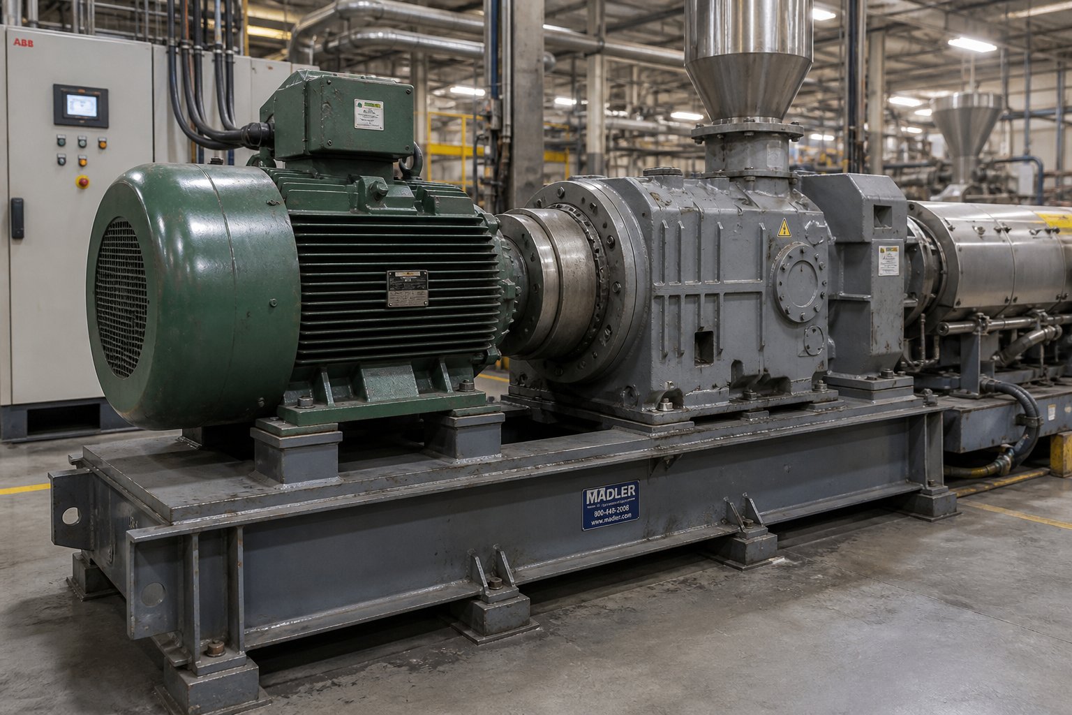
A gearbox rated for 15,000 Nm means nothing if the motor feeding it delivers the wrong speed, the wrong torque profile, or — worse — more power than the gears and bearings can safely absorb. The twin screw extruder gearbox drive system is not two separate purchases bolted together. It is a single mechanical circuit where the motor defines the energy input and the gearbox shapes that energy into the exact speed and torque the screws require. Treating them as independent selections is one of the most common — and most costly — specification errors in extrusion line procurement.
Matching Motor Power to Gearbox Input Capacity
Every gearbox has a maximum rated input power, expressed in kilowatts. The motor connected to it must not exceed this value under any operating condition — including transient overloads during startup, material surges, or die pressure spikes. Sounds obvious, yet the mismatch happens more often than you would expect.
Why? Because motors are sometimes oversized "for future capacity." A plant installs a 400 kW motor on a gearbox rated for 350 kW input, reasoning that they will rarely run at full power. The problem is that without a torque-limiting control on the drive, any process upset that demands full motor output sends 400 kW through gears and bearings sized for 350 kW. The overload may last only seconds, but those seconds concentrate stress on gear tooth roots and bearing raceways at levels far above their fatigue design points. Repeated transient overloads accumulate damage invisibly — until a tooth cracks or a bearing spalls weeks later, with no obvious connection to the event that caused it.
The safest approach is to match motor rated power to the gearbox rated input power within a narrow band, and to configure the variable frequency drive (VFD) with a current limit or torque limit that prevents the motor from ever exceeding the gearbox's mechanical capacity. This electronic safeguard costs nothing to implement during commissioning and can save the price of a new gearbox over the machine's life.
Drive System Integration with VFDs
Modern twin screw extruder lines almost universally use AC motors controlled by variable frequency drives. The VFD adjusts the electrical frequency and voltage supplied to the motor, enabling smooth, stepless speed control from near-zero RPM up to and beyond the motor's base speed. Understanding how this interacts with the twin screw extruder gearbox reduction ratio is essential for getting the screw speed range right.
Consider a practical example. A four-pole AC motor has a base speed of 1,800 RPM when supplied with 480 VAC at 60 Hz. Pair it with a gearbox that has a 6:1 overall reduction ratio, and the maximum screw speed at motor base speed is 300 RPM. Need 600 RPM at the screws? You either choose a lower reduction ratio (say 3:1) or a higher motor base speed — each option carrying different torque implications.
Here is where the constant-torque versus constant-power distinction becomes critical. Below the motor's base speed, the VFD operates in a constant-torque region: as speed decreases, torque remains available at its full rated value while horsepower drops proportionally. This is ideal for low-speed, high-torque processes like reactive extrusion or devolatilization. Above base speed, the motor enters a constant-power (or even reduced-power) region where torque decreases the faster you go. Running screws in this extended speed range means you have less torque available — a critical consideration for high-fill compounding applications that need maximum torque at high RPM.
The twin screw extruder gearbox reduction ratio, then, is not just a speed conversion factor. It is the lever that positions your most-used screw speeds within the motor's constant-torque zone, where full power and full torque are simultaneously available. A well-chosen ratio keeps the motor operating at 60 to 90% of base speed during typical production — right in the efficiency sweet spot where electrical losses are lowest and thermal loading is manageable. A poorly chosen ratio forces the motor to run either at the bottom of its speed range (where cooling fan performance drops and the motor risks overheating) or above base speed (where torque falls off and the process becomes power-limited).
Energy efficiency ties directly into this twin screw extruder gearbox and motor matching decision. A motor running continuously at 30% of base speed wastes energy through poor power factor and reduced motor efficiency. The same motor, paired with a different gearbox ratio that allows it to run at 70% of base speed for the same screw RPM, can cut electricity consumption by 5 to 10% — a meaningful saving on a line that runs 8,000 hours per year.
How Processing Demands Influence Motor-Gearbox Pairing
Different extrusion applications live in completely different corners of the speed-torque map, and the motor-gearbox combination must be tailored accordingly.
High-speed compounding of engineering thermoplastics — think glass-filled nylon or polycarbonate blends — demands screw speeds of 600 to 1,200 RPM at high torque. This combination requires a relatively low gearbox reduction ratio (to allow high output speed) paired with a high-power motor that stays in the constant-torque zone across the working range. The gearbox must be rated for the highest specific torque class (Md/a³ above 13 Nm/cm³) to handle the combination of speed and load without exceeding gear tooth or bearing fatigue limits.
Low-speed reactive extrusion or devolatilization, on the other hand, may operate at 50 to 200 RPM with very high torque demand per shaft. Here, a higher gearbox reduction ratio multiplies motor torque more aggressively, and the motor can be smaller in kilowatt rating because the power requirement (torque times speed) is lower at reduced RPM. The gearbox thrust bearing system becomes the critical constraint, since long residence times and high melt viscosities generate substantial back-pressure forces.
PVC profile extrusion with counter-rotating screws sits at the low end of the speed range — sometimes below 30 RPM. These applications use high-ratio gearboxes and relatively modest motors, but the drive must provide stable, smooth speed regulation at very low frequencies. Closed-loop drives with encoder feedback are often necessary here to maintain precise speed control, since sensorless vector drives lose accuracy at the lowest end of the speed range.
The gearbox and motor should always be specified as a matched system, not selected independently — because the reduction ratio, torque capacity, and speed range only make sense as a coordinated set.
Getting this match right at the specification stage prevents years of operating compromises. But even a perfectly matched drive system eventually needs replacement parts — a new set of bearings, a rebuilt gear train, or sometimes a complete gearbox unit. Knowing where to source these components, what technical data to have ready, and how to evaluate OEM versus aftermarket options can mean the difference between a two-week rebuild and a three-month wait.
Sourcing Gearbox Components and Replacement Parts
A perfectly matched motor-gearbox system still has a finite service life. Bearings fatigue, gear teeth pit, seals harden — and when the oil analysis or vibration data says it is time, you need parts. Fast. The sourcing decision you make at that moment determines whether the line is back up in days or sitting idle for months. And for maintenance engineers and plant buyers, navigating the landscape of twin screw extruder gearbox manufacturers is rarely straightforward, especially when the original equipment maker has discontinued your model or quotes a lead time that stretches into the next fiscal quarter.
OEM vs. Aftermarket vs. Custom Gearbox Sourcing
Three distinct paths exist for sourcing a replacement gearbox or internal components, and each carries its own balance of risk, cost, and convenience. Your choice depends on the machine's age, the urgency of the repair, and how much budget flexibility you have.
OEM Replacement
- Pros: Guaranteed dimensional and metallurgical match to the original design. Full engineering documentation available. Warranty support from the machine builder. No reverse-engineering risk — every tolerance, material specification, and heat treatment protocol mirrors the original.
- Cons: Typically the highest twin screw extruder gearbox prices of the three options — sometimes two to three times the cost of an aftermarket equivalent. Lead times can stretch to 12 to 20 weeks for built-to-order units. Older models may be entirely discontinued, leaving no OEM path at all. Industry data from spare parts pricing analyses shows complete gearbox replacements ranging from roughly $1,800 to $3,800 for standard models, but specialized or large-diameter units can far exceed that range.
Aftermarket Manufacturers
- Pros: Competitive pricing, often 30 to 50% below OEM equivalents. Faster lead times from manufacturers who maintain semi-finished stock or standardized platforms adaptable to multiple machine brands. Many aftermarket twin screw extruder gearbox manufacturers have built deep expertise in specific OEM platforms, producing drop-in replacements with comparable quality.
- Cons: Quality varies significantly between suppliers. Material certifications, gear grinding accuracy, and bearing specifications must be verified independently — not all aftermarket producers hold the same tolerances as the OEM. Warranty terms may be more limited.
Custom-Built Gearboxes
- Pros: The only viable option when OEM parts are discontinued and no direct aftermarket replacement exists. A customized twin screw extruder gearbox can be reverse-engineered from physical samples, original drawings, or detailed dimensional measurements. This path also allows performance upgrades — specifying higher-grade bearings, improved gear materials, or tighter tolerances than the original design. Particularly valuable for older European or Japanese machines where parts availability has dried up.
- Cons: Requires accurate source data. If the original drawings are lost and the existing gearbox is too damaged to measure precisely, the reverse-engineering process adds time and cost. Prototyping risk exists — the first unit may require fitment adjustments.
For many plant buyers, the practical reality is a hybrid approach: sourcing some components from the OEM when available and affordable, filling gaps with aftermarket or custom parts where necessary. The global supply landscape has shifted considerably in recent years, with capable twin screw extruder gearbox factory operations expanding across Asia and offering credible alternatives to traditional European suppliers. A china twin screw extruder gearbox, produced by a manufacturer with the right CNC grinding equipment and metallurgical controls, can match or closely approach European quality at a fraction of the delivered cost — but due diligence on material certifications and quality systems remains essential. Similarly, growing demand for twin screw extruder gearbox in India has driven the emergence of regional manufacturers and service centers that reduce lead times for plants operating in South and Southeast Asia.
What Specifications to Prepare Before Requesting a Quote
Whether you approach an OEM, aftermarket supplier, or custom builder, showing up without the right technical data wastes everyone's time and invites costly miscommunication. Before picking up the phone or sending an inquiry email, gather the following information:
- Screw center distance (a) — The exact distance in millimeters between the two output shaft centerlines. This is the non-negotiable geometric anchor of the entire gearbox. Measure it from the existing unit or reference the extruder's original specification sheet.
- Output shaft dimensions — Shaft diameter, length, keyway size, spline profile (if applicable), and coupling interface details. Include tolerances if available — a shaft that is 0.02 mm oversized will not fit the screw coupling.
- Torque rating per shaft — The maximum continuous torque each output shaft must deliver, expressed in Newton-meters (Nm). Include the specific torque value (Md/a cubed) if you know the gearbox class.
- Maximum output speed (RPM) — The highest screw speed the gearbox must support, which determines the reduction ratio in combination with the motor's base speed.
- Input shaft specifications — Diameter, rotation direction, coupling type (flange, spline, keyed), and the motor power rating the input must accept.
- Axial thrust rating — The maximum forward thrust the gearbox thrust bearings must absorb, in kilonewtons (kN). This is critical and frequently omitted from inquiries.
- Mounting configuration — Foot-mounted, flange-mounted, or integrated base frame. Include bolt pattern dimensions and any critical envelope constraints (height, width, length limitations imposed by the existing machine frame).
- Rotation direction — Co-rotating or counter-rotating, and which shaft rotates clockwise when viewed from the output end.
- Lubrication system type — Splash lubrication, forced circulation, or external oil cooling loop. This affects housing design and port locations.
- Original gearbox nameplate data — Manufacturer, model number, serial number, and year of manufacture. Even if the OEM no longer supports the model, this information helps aftermarket suppliers identify the exact platform and any known design revisions.
Having this data organized in a single document — or better yet, accompanied by dimensioned drawings or photographs of the existing unit — dramatically accelerates the quoting process and reduces the risk of receiving a gearbox that does not fit.
Sourcing Related Extruder Spare Parts Alongside Gearbox Components
A gearbox rebuild rarely happens in isolation. When you open the machine for a major gearbox replacement or overhaul, the practical reality is that other wear components are due for attention at the same time. Screw elements that have been running for six to twelve months may be approaching their radial wear limits. Barrel liners exposed to abrasive fillers may show bore enlargement. Heater bands, thermocouples, die heads, and pelletizing blades all have finite service lives that frequently overlap with gearbox maintenance windows.
Consolidating these orders with a single supplier familiar with extrusion equipment saves procurement time and reduces the coordination headaches that come with managing five or six separate vendors during a tight shutdown window. NANHAIYA, for example, offers a broad catalog of extruder spare parts — including screw-related components, heater bands, thermocouples, die heads, pelletizing blades, and custom parts manufactured from drawings or physical samples — that allows maintenance teams to source multiple replacement items from one source rather than chasing individual components across different suppliers. This kind of consolidated procurement is especially useful for machine rebuilders who handle older lines where original spare parts are scattered across discontinued catalogs.
Twin screw extruder gearbox manufacturers in India and across Asia have similarly expanded their service offerings beyond gearboxes alone, often stocking or manufacturing complementary extruder wear parts. Whether you source locally or internationally, the key principle remains the same: treat the gearbox overhaul as a system-level maintenance event, not an isolated component swap. Inspect every wear surface you can access while the machine is apart. Replace anything approaching its service limit. The incremental cost of replacing a set of screw elements or heater bands during a gearbox overhaul is a fraction of the cost of tearing the machine down again three months later to address the parts you left in place.
The most expensive spare part is the one you did not order during the planned shutdown — because it will demand its own unplanned shutdown later.
Sourcing decisions, like every other aspect of gearbox engineering covered in this article, ultimately come back to preparation. Know your specifications before you call a supplier. Understand the trade-offs between OEM, aftermarket, and custom paths. And when the machine is open, look beyond the gearbox housing to every component the process depends on. That holistic perspective — treating the gearbox not as an isolated box of gears but as the mechanical core of an integrated extrusion system — is what separates engineers who react to failures from those who prevent them.
Frequently Asked Questions About Twin Screw Extruder Gearboxes
1. What is the main function of a gearbox in a twin screw extruder?
A twin screw extruder gearbox performs three simultaneous tasks: it reduces the motor's high rotational speed, multiplies the available torque, and splits that torque equally between two closely spaced output shafts. This equal torque distribution is critical because even a small imbalance — say 55/45 percent — causes screw deflection, uneven barrel wear, and inconsistent melt quality. The gearbox also houses thrust bearings that absorb the enormous axial forces generated as screws push molten polymer against die resistance, with back-pressure loads reaching up to 3,400 kN on large production units.
2. Why is a twin screw extruder gearbox more expensive than a single screw gearbox?
The cost difference stems from the center distance constraint. Twin screws intermesh, forcing their shaft centerlines extremely close together — often just a few tens of millimeters apart. The gearbox must deliver high torque through output shafts at this tight spacing, yet the gears and bearings needed for that torque demand more physical space than the center distance allows. Designers solve this with multi-stage reduction, bilateral distributor shafts, and double-sided symmetrical drive structures that require exceptional machining precision. These complex internal architectures, combined with tighter manufacturing tolerances and specialized thrust bearing systems, make the twin screw gearbox the most expensive single component on the extrusion line.
3. How often should you change the oil in a twin screw extruder gearbox?
A general baseline for synthetic gear oils is every 4,000 to 6,000 operating hours, but condition-based oil changes driven by regular analysis are far more effective than fixed schedules. Drawing oil samples every 500 to 1,000 hours and testing for particle count, viscosity shift, moisture content, acid number, and spectrographic metals reveals the actual internal condition. If the acid number climbs above 4.0 mg KOH/g or moisture exceeds 300 ppm, the oil should be replaced immediately regardless of hours in service. Always follow the gearbox manufacturer's specified viscosity grade and additive package — substituting an unapproved oil can accelerate ferrous wear dramatically.
4. What does specific torque (Md/a³) mean for twin screw extruder gearboxes?
Specific torque normalizes a gearbox's torque output against the cube of the screw center distance, expressed in Nm/cm³. It strips out machine size and reveals true torque density — how much rotational force the gearbox packs into the tight space between output shafts. Standard gearboxes fall in the 5 to 8 Nm/cm³ range, high-torque units reach 10 to 13 Nm/cm³, and ultra-high-torque designs exceed 15 to 18 Nm/cm³. Higher values enable processing of more viscous materials and heavily filled compounds at greater throughputs. When comparing gearbox options, specific torque is a more meaningful metric than absolute torque because it accounts for the engineering difficulty of the center distance constraint.
5. Can you source replacement parts for discontinued twin screw extruder gearboxes?
Yes, through aftermarket manufacturers or custom-build specialists who reverse-engineer components from physical samples, original drawings, or detailed measurements. This path is especially valuable for older European or Japanese machines where OEM support has ended. Buyers should prepare key specifications before requesting quotes — including screw center distance, output shaft dimensions, torque and thrust ratings, speed range, and mounting configuration. During a gearbox overhaul, it is also practical to consolidate orders for related wear parts such as screw elements, barrel liners, heater bands, and die components. Suppliers like NANHAIYA (nhyscrews.com) offer broad extruder spare parts catalogs including custom parts from drawings or samples, simplifying procurement during major shutdowns.
Written by
Nanhaiya Technical Team
Zhoushan Nanhaiya Plastic Machinery Co., Ltd.
The Nanhaiya technical team supports screw and barrel manufacturing projects through application review, technical communication, custom manufacturing coordination, and production and quality control.
Discuss Your Application
Related Articles
More insights on screw barrel technology and plastics processing.
Your Extruder Feeding Instability Isn't Random — Here's Why
Oct 22, 2026
Extruder feeding instability causes surging output and scrap. Learn the 6 root causes, polymer-specific fixes, wear diagnostics, and preventive protocols.
Read Article
Parallel Twin Screw Extruder for Compounding Demystified: Lab to Line
Oct 21, 2026
Learn how a parallel twin screw extruder for compounding works—from screw element design and zone configuration to lab-to-production scale-up and process optimization.
Read Article
Twin Screw Extruder for PVC: The Setup Mistake Draining Profit
Oct 21, 2026
Learn how to match twin screw extruder configurations to PVC applications. Covers conical vs parallel, counter-rotating vs co-rotating, wear management, and troubleshooting.
Read ArticleLooking for something else?
Search by material, symptom or product and jump straight to the relevant page.
These are navigation suggestions based on keyword matching — not a quotation, not a delivery commitment, and not a substitute for engineering review. Final specification is confirmed by our engineers against your drawings and processed material.
Need help with screw barrel selection?
Share your machine model, processed material and application. Our team can help with pricing and technical support.