

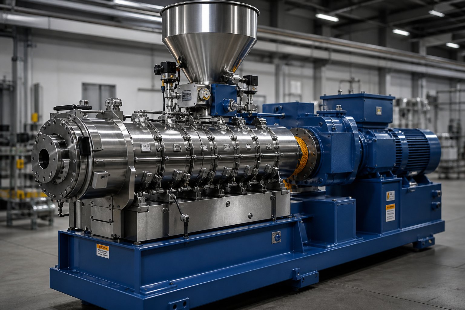
What Twin Screw Extruder Specifications Actually Define
Twin screw extruder specifications are the measurable geometric, mechanical, thermal, and volumetric parameters that define a machine's processing capability, throughput limits, and material compatibility. They are the technical language every engineer, procurement professional, and production team must speak fluently before selecting, configuring, or optimizing a twin screw extruder for any application.
Forget brand names for a moment. A twin-screw extruder does not succeed or fail because of a logo on the gearbox housing. It succeeds or fails because its specifications either match or miss the demands of the target process. That distinction matters more than most buyers realize.
Why Specifications Drive Every Extrusion Decision
Imagine you need to compound a highly filled polypropylene at 500 kg/hr with two vacuum venting stages. Can the machine handle that? The answer is not buried in a marketing brochure. It lives in the specifications: Does the screw diameter support that throughput? Is the L/D ratio long enough for multiple mixing and venting zones? Can the gearbox deliver sufficient torque at the required screw speed without exceeding its limits?
Specifications are what determine whether an extruder system can achieve a target output, process a specific polymer formulation, or integrate into an existing production line. Every decision in twin screw extrusion, from initial equipment selection to screw configuration to process scale-up, traces back to a quantifiable parameter on a spec sheet.
Key Specification Categories at a Glance
This article breaks down the critical specification categories that govern every twin screw extruder system:
- Geometric parameters - screw diameter, L/D ratio, Do/Di ratio, and centerline distance
- Mechanical parameters - torque density, motor power, and maximum screw RPM
- Thermal parameters - barrel zone count, heating capacity, and cooling channel design
- Volumetric parameters - free volume, specific volume, and specific throughput
Specifications are deeply interconnected - changing one parameter cascades through the entire system. Increasing screw diameter, for example, affects free volume, torque requirements, heat transfer characteristics, and throughput capacity simultaneously.
You'll notice throughout this guide that no single specification tells the full story. A high motor power rating means little without understanding the gearbox torque limits that constrain it. An impressive maximum RPM is irrelevant if the Do/Di ratio cannot support the shaft strength needed at those speeds. The real skill in evaluating twin screw extrusion equipment lies in reading specifications as a system, not as isolated numbers.
The sections ahead decode each category in detail, starting with the geometric parameters that physically shape every processing outcome.
Core Geometric Specifications That Shape Processing Capability
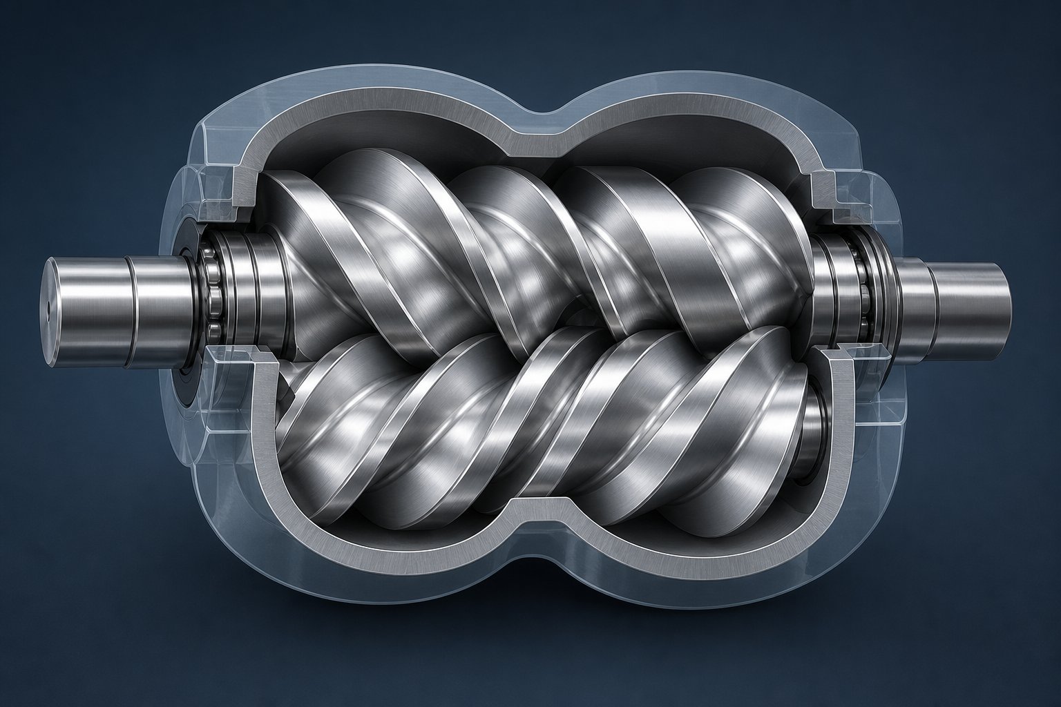
Every screw extruder is defined first by its geometry. Before motor power matters, before torque density becomes relevant, the physical dimensions of the twin screw and barrel establish the boundaries of what a machine can and cannot do. Three geometric specifications form this foundation: screw diameter and L/D ratio, the Do/Di ratio, and centerline distance. Together, they determine throughput capacity, mixing intensity, residence time, and the critical self-wiping behavior that makes co-rotating twin screw extrusion so effective.
Screw Diameter and L/D Ratio Fundamentals
Screw diameter is the single specification that sets the baseline scale of your entire process. Lab-scale twin screw extruders start with diameters as small as 12 mm to 16 mm, designed for processing gram-level batches during formulation development. Pilot-scale machines typically range from 26 mm to 50 mm. Production-class equipment spans from 50 mm up to 300 mm or beyond, where throughputs can reach thousands of kilograms per hour.
Why does diameter matter so much? Because volumetric capacity scales roughly with the cube of the screw diameter. Double the diameter and you do not simply double throughput - you increase it by a factor of approximately eight. That nonlinear relationship is why a seemingly modest jump from a 50 mm to a 70 mm machine represents a dramatic leap in production capability.
The L/D ratio - the total screw length divided by the screw diameter - determines how many functional processing zones you can fit along the barrel. Industry-standard L/D ratios typically range from 20:1 to 48:1, though modern compounding machines commonly operate between 32:1 and 52:1. Think of the L/D ratio as the processing real estate available on your machine:
- Short L/D ratios (20:1 to 28:1) - suitable for applications requiring high shear mixing with minimal residence time, such as color masterbatch production or thermally sensitive materials
- Medium L/D ratios (28:1 to 36:1) - the most common range, balancing mixing intensity and residence time for general compounding, fiber reinforcement, and polymer modification
- Long L/D ratios (36:1 to 52:1) - required for complex processes demanding multiple mixing zones, vacuum venting stages, side-feeding ports, and extended residence time for devolatilization or reactive extrusion
A longer L/D ratio allows more barrel zones for tasks like solids conveying, melting, dispersive mixing, distributive mixing, venting, and pressure building. But longer is not automatically better. Excessive L/D increases energy consumption, extends residence time (raising degradation risk for heat-sensitive polymers), and adds to machine cost. The right ratio matches the complexity of your process - nothing more, nothing less.
Do/Di Ratio and Its Impact on Free Volume
Here is where twin screw barrel geometry gets genuinely interesting - and where most specification discussions fall short. The Do/Di ratio, the outer screw diameter (Do) divided by the inner screw diameter (Di, also called the root or core diameter), governs a fundamental trade-off that shapes every processing outcome.
A higher Do/Di ratio (for example, 1.71 or 1.80) means deeper screw channels. Deeper channels provide more free volume - the open space inside the barrel available for material. More free volume translates to higher intake capacity, greater throughput potential, and reduced shear rates at a given screw speed. However, deeper channels leave a smaller shaft cross-section at the core, which limits how much torque the shaft can transmit without mechanical failure.
A lower Do/Di ratio (for example, 1.46 or 1.55) creates shallower channels. The shaft cross-section is larger, enabling the gearbox to transmit significantly more torque to the screw elements. This is critical for high-energy applications like compounding engineering thermoplastics, where the torque limit of the twin screw is often the bottleneck. The trade-off? Less free volume and higher shear rates in filled channels.
As analysis from Xtrutech demonstrates, the shear rate relationship between these geometries follows a practical rule of thumb: the shear rate at 300 RPM on a Do/Di = 1.55 extruder is roughly equivalent to that on a Do/Di = 1.80 machine operating at 500 RPM. That difference has real implications for processing windows, especially with shear-sensitive or thermally sensitive materials.
| Do/Di Ratio | Channel Depth | Free Volume | Torque Capacity | Shear Rate (at equal RPM) | Typical Application Focus |
|---|---|---|---|---|---|
| 1.46 - 1.55 | Shallow | Lower | High | Higher | Engineering plastics, high-torque compounding |
| 1.55 - 1.65 | Moderate | Moderate | Moderate | Moderate | General-purpose compounding, polymer blends |
| 1.65 - 1.80 | Deep | Higher (~40% more than 1.55) | Lower | Lower | High-throughput, low-energy materials, powder coatings |
The deeper-channel geometry of a Do/Di = 1.80 design offers roughly 40% more free volume compared to a 1.55 design of the same outer diameter. That advantage is substantial for feed-limited applications where you need to get low-bulk-density materials into the machine efficiently. But for torque-limited applications - where the motor has power available but the shaft cannot transmit it - the 1.55 geometry wins decisively.
Centerline Distance and the Self-Wiping Geometry
Centerline distance is the spacing between the rotational axes of the two screws. It sounds simple, but this specification is geometrically locked to both the outer diameter and the Do/Di ratio through a mathematical constraint that ensures self-wiping contact in co-rotating intermeshing designs.
For a standard double-flighted (bi-lobal) screw profile, the geometric relationship requires that the centerline distance (A) must be at least 0.707 times the outer diameter (Do) for the self-wiping profile to function. The inner diameter (Di) is then determined by the equation: Di = 2A - Do. This means that once you fix the outer diameter and centerline distance, the channel depth and Do/Di ratio are no longer free choices - they are locked by geometry.
Why does self-wiping matter? In the intermesh zone - the region where the two screws overlap - co-rotating flight tips move in opposite directions. This opposing motion continuously pushes material out of the intermesh zone, preventing stagnation, dead spots, and material degradation. The resulting open figure-eight flow pattern forces material through alternating compression and expansion as the channel volumes change during rotation. These alternating extensional flows are where some of the most effective dispersive mixing occurs in a twin screw extruder.
The intermesh zone geometry, governed by the ratio of centerline distance to outer diameter (A/Do), also determines the compression ratio between expanding and contracting channel sections. Research shows that the compression ratio changes surprisingly little with the Do/Di ratio. However, since the volume of material subjected to elongational flow is the product of compression ratio and free volume, a higher Do/Di ratio (with its greater free volume) generates more total elongational mixing - potentially over 30% more compared to lower-ratio designs at the same screw speed.
These geometric relationships are not academic abstractions. They dictate the real-world processing envelope of every twin screw and barrel combination. A machine's Do/Di ratio and centerline distance determine whether it excels at high-torque, shear-intensive compounding or high-volume, throughput-driven processing. Understanding this trade-off is essential before comparing any two machines - even those with identical screw diameters.
Geometry, though, only tells part of the story. The same screw diameter and Do/Di ratio behave very differently depending on whether the screws rotate in the same direction or in opposite directions - a distinction that introduces an entirely different set of specification trade-offs.
Co-Rotating vs. Counter-Rotating Specification Differences
Rotation direction changes everything. Two machines with identical screw diameters, the same Do/Di ratio, and matching L/D lengths will produce fundamentally different processing behaviors depending on whether the screws spin in the same direction or in opposite directions. The specifications diverge across nearly every measurable parameter - RPM range, mixing mechanism, pressure generation, and application suitability. Understanding the differences between a co rotating twin screw extruder and its counter-rotating counterpart is essential for matching machine capabilities to process demands.
How Co-Rotating Specifications Differ from Counter-Rotating
In a co rotating twin screw extruder, both screws turn in the same direction with a fully intermeshing geometry. Material follows a figure-eight flow path, getting forcibly handed off from one screw to the next at the intermesh zone. This produces intense shear fields both between the screws and between the screw flights and barrel wall. Modern co-rotating machines operate at speeds up to 1200+ RPM, and even residence times as short as five seconds are possible. That combination of high speed, modular screw design flexibility, and powerful dispersive and distributive mixing makes co-rotating configurations the dominant choice for compounding, reactive extrusion, and devolatilization.
Counter-rotating designs flip the script. The screws rotate in opposite directions, and at the intermesh zone, material gets drawn in and compressed rather than wiped across. A calendering effect develops in this region, where material undergoes repeated compressive and elongational deformation under relatively gentle conditions. Shear stress and associated heat generation stay lower than in co-rotating machines. That matters enormously for thermally sensitive materials like rigid PVC, which decomposes easily under high-shear conditions.
Counter-rotating machines also generate pressure differently. Closed "C-shaped" chambers formed between intermeshing flights function essentially as positive displacement pumps, building stable die pressure without requiring an external gear pump. Co-rotating extruders, by contrast, are semi-drag flow devices with limited inherent pressure-building capability - a gear pump or single screw pump is often attached for shape extrusion applications requiring tight dimensional control.
Specification Comparison Across Configurations
When you compare co rotating and counter rotating twin screw extruder specifications side by side, the differences become quantifiable. The table below summarizes the key parameters that separate these two configurations:
| Specification | Co-Rotating Intermeshing | Counter-Rotating Intermeshing |
|---|---|---|
| Typical Max RPM | 1200+ (high-speed energy input) | Up to 600 (high-speed) / Under 50 (low-speed late fusion) |
| Do/Di Ratio Range | 1.40 to 1.80 | Typically around 1.50 |
| Common L/D Ratio Range | 32:1 to 52:1 | 20:1 to 40:1 |
| Lobe Count | 2 (bilobal at standard flight depths) | Up to 6 (hexalobal possible at same flight depth) |
| Primary Mixing Mechanism | High shear via kneading blocks, extensional flow at intermesh | Calendering effect - compressive and elongational deformation |
| Self-Wiping Capability | Yes - strong self-wiping with narrow residence time distribution | Limited - material forced through calender gap instead |
| Pressure Generation | Low inherent capability; gear pump often required | High - positive displacement via C-shaped chambers |
| Screw Design Modularity | Highly modular with segmented elements on splined shafts | Modular or one-piece; less element variety typically available |
| Common Applications | Compounding, reactive extrusion, devolatilization, masterbatch | PVC profile/pipe extrusion, gentle mixing of heat-sensitive materials |
Notice the lobe count difference. Because counter-rotating elements mesh like gears rather than wiping past each other, they support up to six lobes at the same flight depth where co-rotating designs are limited to two. More lobes mean more mixing events per screw revolution, which partially compensates for the lower operating speeds. That said, higher screw speeds in counter-rotation cause screw deflection and metal-to-metal contact at the intermesh, which is fundamentally what limits the attainable RPM for this configuration.
Conical vs. Parallel Counter-Rotating Designs
Counter-rotating machines come in two distinct geometric formats, and their specifications reflect very different design philosophies.
A parallel twin screw extruder maintains constant screw diameter and centerline distance from feed to discharge. This consistent geometry supports modular barrel construction, segmented screw elements, and the flexibility to reconfigure processing zones. Parallel counter-rotating designs dominate PVC profile and pipe extrusion, where stable pressure generation and low-shear processing at high fill levels are priorities.
A conical twin screw extruder takes a fundamentally different approach. The screws taper from a larger diameter at the feed section to a smaller diameter at the discharge. This tapering geometry creates natural compression as material moves forward, and the small-diameter discharge end provides a low-volume area with strong positive pumping against die head pressures. The reduced diameter at the tip also minimizes rotational shear and heat generation right where the material exits - a significant advantage for temperature-sensitive formulations. Conical designs are widely used for PVC sheet, pipe, and profile extrusion where that combination of gentle feeding, progressive compression, and low-shear discharge matters most.
Choosing between these configurations comes down to process requirements:
- Co-rotating parallel - compounding, reactive extrusion, devolatilization, and any application demanding intense mixing with modular screw design flexibility
- Counter-rotating parallel - PVC profiles, pipes, and applications requiring high pressure generation with low shear at moderate speeds
- Counter-rotating conical - sheet and pipe extrusion for heat-sensitive materials, where natural compression and gentle discharge are priorities
Each configuration's specifications are optimized for specific processing outcomes. The geometry dictates the mixing mechanism, the mixing mechanism dictates the material compatibility, and the material compatibility dictates the application. But geometry and rotation direction only define the processing envelope - the motor and gearbox determine how much energy actually reaches the screws inside that envelope.
Motor Power and Torque Specifications Explained
A twin screw extruder machine can have the perfect screw geometry, an ideal Do/Di ratio, and an L/D length matched precisely to the process - and still underperform if the motor and gearbox cannot deliver sufficient energy to the screw elements. Motor power, gearbox torque, and screw speed form a tightly coupled triad where each parameter constrains the other two. Misunderstanding any one of them leads to machines that hit their limits long before the process demands it.
Motor Power Ratings and What They Control
Motor power, measured in kilowatts (kW) or horsepower (HP), represents the total energy available for polymer melting, dispersive mixing, and material conveying during screw extrusion. But raw power ratings tell only part of the story. The relationship between power, torque, and speed follows a fixed formula:
Torque (Nm) = 9550 x kW / max RPM
This means a 200 kW motor geared for 600 RPM delivers exactly the same torque as a 400 kW motor geared for 1200 RPM - approximately 3,183 Nm total across both shafts. If your process operates below 600 RPM, the larger motor offers zero additional torque. You are paying for speed capability you may never use.
Imagine two configurations of the same 60 mm double screw extruder machine: one fitted with a 200 kW drive at 600 RPM max, the other with a 400 kW drive at 1200 RPM. For any process running between 0 and 600 RPM, both setups are mechanically identical. The higher-power configuration only provides an advantage when processes genuinely benefit from screw speeds above 600 RPM - typically high-shear compounding or reactive extrusion applications where intense dispersive mixing is required.
The practical takeaway? Always evaluate motor power alongside its geared speed range. A high-power motor at low speed delivers high torque and strong melting capability. The same power at high speed delivers lower torque per revolution but faster material turnover and higher shear rates. The right balance depends entirely on what the target material demands.
Gearbox Torque Density as a Critical Specification
Here is where many equipment evaluations go wrong. The motor may have plenty of power available, but the gearbox and shaft geometry constrain how much torque actually reaches the screw elements. Torque density - measured in Nm/cm3 - quantifies the torque transmitted per unit of shaft cross-sectional area, and it is often the true limiting specification in high-output applications.
Modern high-performance twin screw extruder machines achieve torque densities of 18 Nm/cm3, representing roughly a 30% increase over previous-generation equipment. That jump is significant: higher torque density enables processing of materials that were previously torque-limited, including glass-filled polyamide and mineral-reinforced polypropylene. Standard machines typically operate in the 5 to 10 Nm/cm3 range, while high-torque platforms push beyond 15 Nm/cm3.
| Torque Density Range (Nm/cm3) | Classification | Typical Application Suitability |
|---|---|---|
| 5 - 10 | Standard | Unfilled polymers, low-viscosity blends, color concentrates |
| 10 - 15 | High torque | Moderate-fill compounding, engineering thermoplastics |
| 15 - 18+ | Ultra-high torque | Highly filled compounds, glass-reinforced materials, reactive extrusion |
A reliable operating guideline is to run at 80% of continuous torque capacity and 80% of maximum speed. That margin accounts for process variations, cold-start torque spikes (which can exceed steady-state values by 20 to 40%), and the reality that peak torque ratings on spec sheets often represent intermittent, not continuous, duty. Treating peak torque as the buying number is one of the most common - and costly - specification mistakes in the industry.
Understanding Specific Energy Input
Specific energy input (SEI) bridges the gap between machine parameters and material outcomes. Measured in kWh/kg, SEI quantifies the energy delivered per unit mass of material processed. It is calculated in two steps:
- Applied power: kW (applied) = kW (motor rating) x % torque x (RPM running / max RPM) x 0.97 (gearbox efficiency)
- Specific energy: SEI = kW (applied) / throughput (kg/hr)
Consider a practical example: a 40 mm twin screw extruder machine processing mineral-filled polypropylene at 160 kg/hr, running at 400 RPM with 68% torque on a 56 kW motor (600 RPM max). The applied power is 56 x 0.68 x (400/600) x 0.97 = 24.6 kW, yielding an SEI of approximately 0.154 kWh/kg.
Specific energy input is the single specification that connects machine parameters to material outcomes.
Why does this number matter so much? A lower SEI means less mechanical energy is entering the polymer - suitable for heat-sensitive materials or processes where minimal shear history is desirable. A higher SEI indicates more intensive energy input, which may be necessary for dispersive mixing of agglomerated fillers or for driving chemical reactions in reactive screw extrusion. Critically, SEI records serve as a diagnostic fingerprint: if a product that consistently runs at 0.25 kWh/kg suddenly drops to 0.16 kWh/kg with no hardware or process changes, the feedstock has almost certainly changed.
SEI also enables meaningful comparisons across different machine sizes and even different processing technologies. A process developed on a lab-scale unit at a particular SEI value provides a reliable target when scaling to production equipment - as long as geometric similarity (Do/Di ratio, screw profile style) is maintained between the two machines.
Motor power, gearbox torque, and specific energy are the mechanical heart of any twin screw extruder specification sheet. Yet these parameters behave very differently depending on machine scale. A 15 mm lab unit and a 200 mm production machine share the same physics, but their specification ranges occupy entirely different territory - a distinction worth exploring in detail.
Lab-Scale to Production-Scale Twin Screw Extruder Specification Ranges
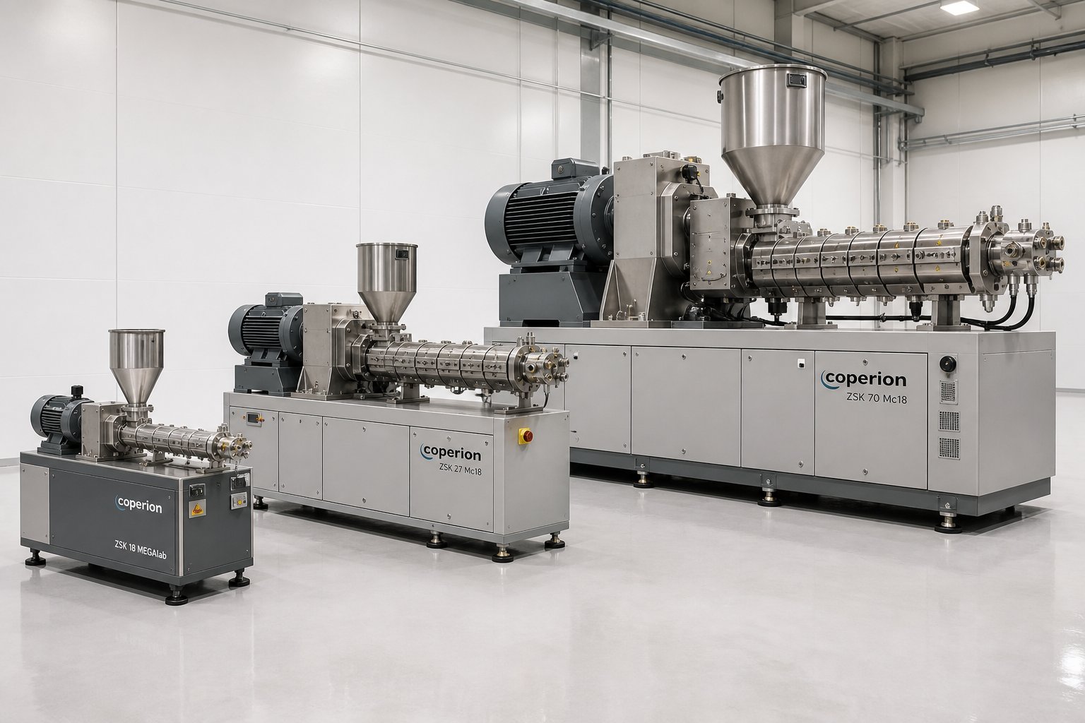
A 15 mm laboratory twin screw extruder and a 200 mm production machine share identical physics - self-wiping geometry, intermeshing screw elements, modular barrel segments. But their specification ranges occupy entirely different territory. Screw speed, motor power, throughput capacity, and even the number of barrel zones scale in ways that are not always intuitive. Engineers developing new formulations on a lab scale twin screw extruder need to understand exactly where their small-scale data sits relative to production reality, and procurement teams evaluating capital equipment need clear specification benchmarks for each machine class.
What follows is a structured comparison across three scales: lab, pilot, and production. These ranges represent general industry standards rather than any single manufacturer's lineup - a reference you can use regardless of the brand on the spec sheet.
Lab-Scale Extruder Specifications
Lab-scale and benchtop twin screw extruder models occupy the smallest end of the specification spectrum, with screw diameters typically ranging from 5 mm to 27 mm. These machines are not designed for throughput. They are designed for material conservation, experimental flexibility, and rapid formulation screening - priorities that shape every specification on the data sheet.
Consider what a 5 mm to 12 mm laboratory extruder actually delivers. Throughputs measured in grams per hour rather than kilograms. Motor power typically under 5 kW, sometimes as low as 0.5 kW. Sample volumes as small as 10 to 15 grams per run. These numbers sound modest until you realize the purpose: every gram of experimental polymer or active pharmaceutical ingredient is expensive, and running hundreds of formulation trials on a production machine would be prohibitively wasteful.
Typical specifications for lab scale extruder models include:
- Screw diameter: 5 mm to 27 mm
- L/D ratio: 20:1 to 40:1 (some micro-compounders use shorter configurations)
- Max RPM: 200 to 1000+ RPM
- Motor power: 0.5 kW to 5 kW
- Throughput range: Grams per hour up to approximately 5 kg/hr
- Barrel zones: 3 to 8 independently heated zones
The smaller diameters (5 mm to 12 mm) are primarily used for basic formulation evaluation and raw material compatibility studies, where minimizing dead space and material consumption are the dominant concerns. Machines in the 16 mm to 27 mm range offer more realistic processing conditions and begin to provide data that can be meaningfully correlated to larger equipment. A laboratory scale extruder at 20 mm or above typically supports gravimetric feeding, multiple barrel configurations, and screw element modularity that closely mirrors production machine architecture.
One critical detail that spec sheets rarely emphasize: heat transfer behavior on lab-scale equipment differs fundamentally from production machines. The surface-area-to-volume ratio is dramatically higher at small diameters, meaning barrel heating and cooling exert a much stronger influence on melt temperature than they do on larger equipment. A process that runs beautifully at 180 degrees C on a 16 mm lab unit may behave entirely differently at the same setpoint on a 70 mm production machine - not because anything is wrong, but because the physics of heat transfer have shifted.
Pilot-Scale Specification Ranges
Pilot-scale twin screw extruders, typically spanning 27 mm to 50 mm in screw diameter, serve a specific and demanding purpose: they bridge the gap between R&D formulation work and full-scale production. Every specification on a pilot-scale machine reflects this bridging function.
Throughput capability jumps significantly compared to lab equipment - ranging from roughly 5 kg/hr to 200 kg/hr depending on the material and screw diameter. Motor power climbs into the 10 kW to 75 kW range. L/D ratios typically match or exceed those available on production equipment (32:1 to 48:1), because the whole point of pilot-scale work is validating a screw and barrel configuration that will transfer directly to larger machines.
Pilot-scale machines also introduce specification considerations that simply do not arise at lab scale:
- Gravimetric feeding accuracy becomes critical as you validate formulation ratios at meaningful throughputs
- Vacuum venting capability can be properly tested with realistic melt seal formation
- Side-feeding for fillers and fibers becomes practical at 35 mm and above, where the barrel bore provides sufficient volume for downstream material addition
- Torque and power consumption data begin to generate SEI values that scale reliably to production conditions
The most valuable function of a pilot-scale unit is producing scale-up data that engineers can trust. A well-designed process on a 35 mm pilot extruder, running at a validated specific energy input and a characterized screw configuration, provides a reliable recipe for configuring a 70 mm or 92 mm production machine. The geometric similarity matters here - matching the Do/Di ratio and screw element style between pilot and production equipment ensures that the mixing, shear, and residence time relationships transfer predictably.
Where pilot-scale specifications fall short is in replicating production-level pressure profiles and die-end behavior. The volumetric flow rates are still modest enough that die pressure, melt uniformity, and strand stability may not reflect what happens at full production throughput. That limitation does not diminish the pilot machine's value for process development, but it does mean that die design and downstream equipment validation typically require a separate production trial.
Production-Scale Specifications and Throughput Ranges
Production twin screw extruders operate in a different specification universe. Screw diameters from 50 mm to 300 mm and beyond. Motor power measured in hundreds of kilowatts - some large-diameter compounding lines draw 1,000 kW or more. Throughputs that can exceed several thousand kilograms per hour for commodity compounding or high-volume recycling operations.
At this scale, the specification priorities shift decisively. Throughput per kilowatt of energy consumed becomes a key economic metric. Gearbox torque density - not just motor power - often defines the machine's production ceiling. Barrel zone count expands to 8, 10, or even 12+ independently controlled segments, each representing roughly 4D of barrel length, providing the thermal control granularity needed for complex multi-stage processes.
Production-scale specifications also reflect the mechanical realities of high-output operation. Barrel liners must handle continuous abrasive contact from filled compounds; nitrided or bimetallic constructions are standard for anything involving mineral fillers or glass fiber reinforcement. Screw elements face similar demands, with PM-HIP tool steel or tungsten carbide coatings specified for aggressive formulations. These metallurgical specifications directly affect machine uptime and maintenance intervals - a production extruder processing 40% glass-filled polyamide will consume screw elements and barrel liners at a fundamentally different rate than one running unfilled polypropylene.
The table below organizes key specification ranges across all three scales. These are general industry-standard values - you will find individual machines that fall outside these ranges, but they represent the typical specification territory for each class.
| Specification | Lab Scale (5 - 27 mm) | Pilot Scale (27 - 50 mm) | Production Scale (50 - 300+ mm) |
|---|---|---|---|
| Screw Diameter Range | 5 mm to 27 mm | 27 mm to 50 mm | 50 mm to 300+ mm |
| Typical L/D Ratio | 20:1 to 40:1 | 32:1 to 48:1 | 32:1 to 52:1 (up to 68:1) |
| Max RPM Range | 200 to 1,000+ RPM | 300 to 1,200 RPM | 300 to 1,200 RPM |
| Motor Power Range | 0.5 kW to 5 kW | 10 kW to 75 kW | 75 kW to 1,000+ kW |
| Approximate Throughput Range | Grams/hr to ~5 kg/hr | 5 kg/hr to 200 kg/hr | 200 kg/hr to 8,000+ kg/hr |
| Typical Barrel Zone Count | 3 to 8 zones | 6 to 10 zones | 8 to 12+ zones |
| Primary Applications | Formulation screening, material compatibility, small-batch R&D, pharmaceutical development | Scale-up validation, process optimization, small production runs, application testing | Compounding, masterbatch, reactive extrusion, recycling, high-volume production |
A few patterns in this table deserve attention. Notice that max RPM ranges converge at pilot and production scales - both classes of machines use similar drive and gearbox technology, just at different power levels. L/D ratios also converge, because the processing zone requirements for complex compounding tasks do not change with machine diameter. What changes dramatically is the power-to-diameter relationship and, consequently, the throughput envelope.
Also worth noting: the throughput range at production scale spans an enormous window. A 50 mm machine processing unfilled polymer might deliver 200 kg/hr, while a 180 mm extruder running a commodity masterbatch can push well beyond 5,000 kg/hr. The same "production-scale" label covers machines with very different economic profiles, capital costs, and operational demands. Screw diameter alone is not a throughput guarantee - actual output depends on the interplay between free volume, screw speed, specific energy requirements of the material, and the torque available from the gearbox.
Whether you are selecting a benchtop twin screw extruder for early-stage pharmaceutical research or specifying a high-throughput production line for polymer compounding, these specification ranges provide the benchmarks for informed comparison. The numbers define what each class of machine can deliver mechanically. But numbers alone do not communicate clearly without a shared vocabulary - and too many specification terms get used loosely, misunderstood, or conflated across the industry.
Key Specification Terms and Barrel Zone Configurations
Specification sheets for twin-screw extruders are dense with terminology that gets used loosely, misunderstood, or outright conflated - even by experienced professionals. When one engineer says "free volume" and another says "volumetric capacity," are they talking about the same thing? Sometimes yes. Sometimes not. And that ambiguity creates real problems during equipment evaluation, scale-up discussions, and troubleshooting conversations between plants and OEMs.
A shared vocabulary eliminates guesswork. The glossary below defines the terms that appear most frequently on specification sheets for screw extruders, written for working professionals who need precision without academic overload.
Understanding specification terminology is the foundation for evaluating any twin screw extruder - regardless of manufacturer or application.
Essential Specification Terminology Defined
You will encounter these terms repeatedly when comparing machines, reviewing quotations, or discussing process requirements with equipment suppliers. Each definition reflects how the term is used in practice across the compounding and extrusion industry.
| Term | Definition |
|---|---|
| Specific Torque | Torque per unit of centerline distance cubed (Nm/a3), used to normalize torque capacity across different machine sizes. Enables meaningful comparison between, say, a 40 mm and a 92 mm extruder by eliminating the scale variable. |
| Volumetric Capacity | The total volume of material the screw channels can contain per unit length of the extruder. Determined by screw geometry - primarily the Do/Di ratio and flight configuration. Higher volumetric capacity supports greater throughput at a given screw speed. |
| Free Volume | The open, unoccupied space inside the barrel bore after subtracting the volume of the screw elements themselves. This is the actual space available for material transport, melting, and mixing. A higher Do/Di ratio increases free volume; a lower ratio decreases it. |
| Specific Energy Input (SEI) | Energy delivered per unit mass of processed material, measured in kWh/kg. Calculated from motor power, torque utilization, screw speed, and throughput rate. SEI connects machine operating parameters directly to melt quality, mixing intensity, and degradation risk. |
| Torque Density | Torque transmitted per unit of shaft cross-sectional area, measured in Nm/cm3. Reflects the mechanical limit of the gearbox and screw shaft combination. Modern high-performance machines achieve 15 to 18+ Nm/cm3. |
| Specific Throughput | Output rate normalized by screw speed, typically expressed as kg/hr/RPM. Provides a speed-independent measure of how efficiently the extruder converts screw rotation into material output. Useful for comparing performance across different operating conditions or machine sizes. |
| Barrel Bore Geometry | The cross-sectional shape of the internal barrel channel - a figure-eight profile in twin-screw designs formed by two overlapping cylindrical bores. The bore dimensions match the screw outer diameter with a tight radial clearance that defines the overflight gap. |
| Overflight Gap | The radial clearance between the screw flight tip and the barrel wall. Typically 0.1 to 0.3 mm depending on machine size and wear tolerance. Material passing through this gap experiences the highest shear rate in the entire extruder - it is the primary site of dispersive mixing action along the barrel wall. |
| Intermesh Zone | The region where the two screws overlap and their flights interact. In co-rotating designs, opposing flight tips in the intermesh zone create alternating compression and expansion that generates powerful extensional flow fields - a key mechanism for dispersive mixing of agglomerates and droplets. |
Keep this table bookmarked. You will find that nearly every equipment discussion, process audit, or scale-up calculation references at least three or four of these terms. Getting them right from the start avoids costly miscommunication downstream.
Barrel Zone Count and Segment Configuration
Barrel zone count is one of the most practical specifications on any twinscrew extruder data sheet, yet it is frequently overlooked in favor of flashier numbers like motor power or max RPM. In reality, the number and arrangement of barrel zones determine your processing flexibility - how many functional operations you can perform along the length of the machine.
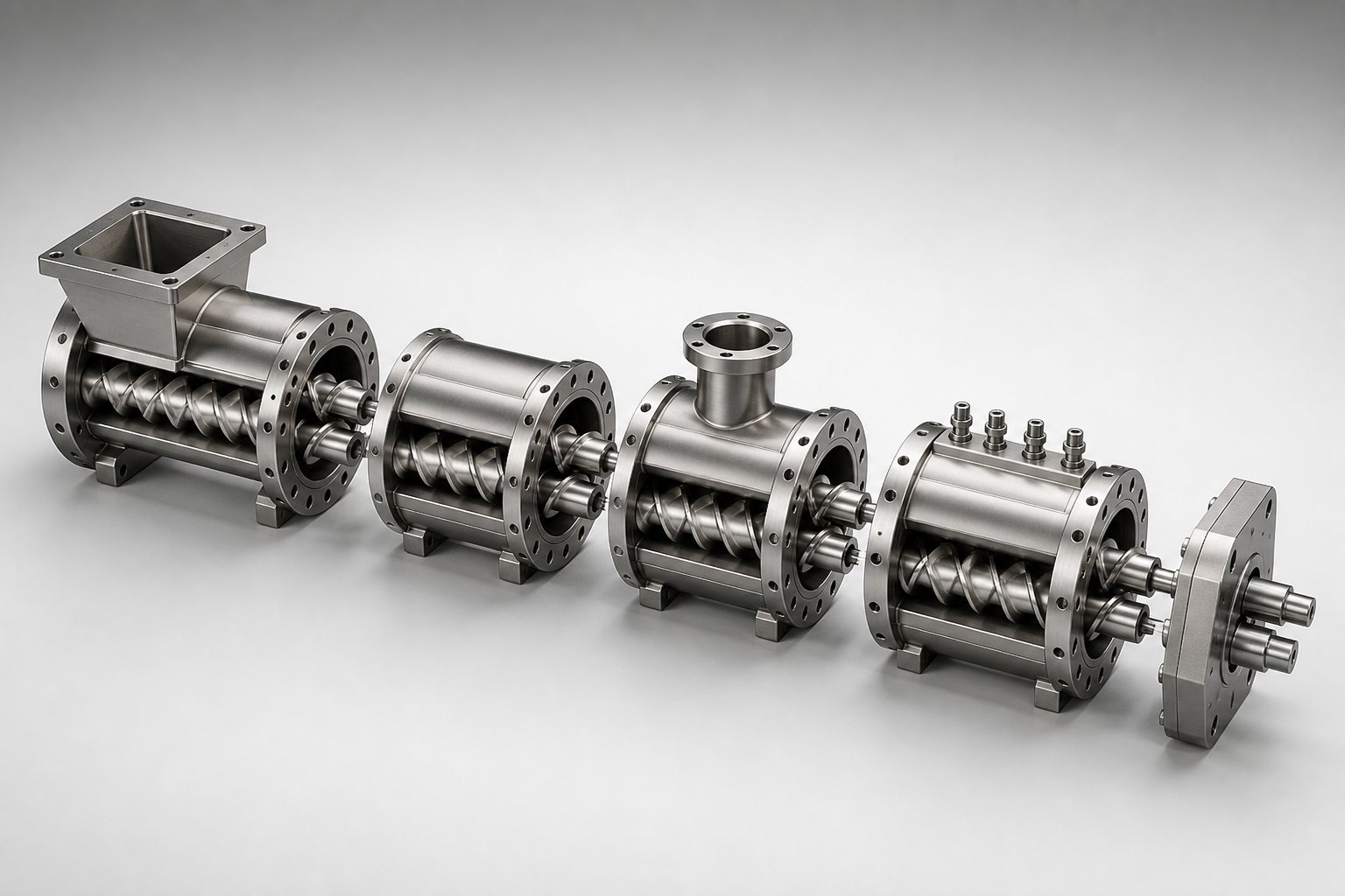
Each barrel zone typically corresponds to one barrel segment that is 4D in length (four times the nominal screw diameter). A 40:1 L/D extruder, for example, consists of ten 4D-length barrel segments, each independently heated and cooled. Some manufacturers use 5D or 6D segments, which changes the zone count for a given L/D ratio, so always confirm both the segment length and the total zone count when comparing machines.
The real power of barrel segmentation lies in how those zones are configured. As Plastics Technology explains, a twin-screw extruder can be viewed as a series of unit operations - solids conveying, melting, mixing, liquid injection, downstream addition, venting, and pumping - that can be arranged as needed to optimize the process. Each barrel section type serves a specific function:
- Open barrel (feed) - features a top opening for material introduction; most commonly placed in the first barrel position, but can be located downstream for split-feed configurations
- Open barrel (vent) - the same basic design used for atmospheric or vacuum venting of volatiles, moisture, or reaction byproducts; typically positioned one to two zones upstream of the die
- Side-feed (combi) barrel - incorporates a secondary figure-eight opening on the side for a twin-screw side stuffer, plus an upstream atmospheric vent opening for entrained air escape; critical for downstream addition of fillers, fibers, or secondary polymers
- Closed barrel - fully encases the melt on all four sides with only the figure-eight screw bore; provides maximum temperature control through complete heater and cooling channel coverage
Imagine you need to compound a glass-fiber-reinforced nylon with vacuum devolatilization. Your barrel configuration might look something like this: open feed barrel at position 1, closed barrels at positions 2 through 4 for conveying and melting, a combi-barrel at position 5 for side-feeding glass fiber with an upstream air vent, closed barrels at positions 6 through 8 for mixing, an open barrel at position 9 for vacuum venting, and a final closed barrel at position 10 before the die. Change the formulation to an unfilled reactive extrusion with liquid injection? You can rearrange segments to place a liquid injection port where the side feeder was and add a second vacuum vent.
This modularity is what makes twin-screw extruders uniquely adaptable. The same base machine - same motor, same gearbox, same screw diameter - can be reconfigured for fundamentally different processes simply by rearranging barrel segments and swapping screw elements. On lab and pilot-scale machines, this reconfiguration might happen daily during development work. On production lines, the layout is typically fixed once validated, though the option to reconfigure remains available if product lines change.
Barrel segment specifications extend beyond just configuration type. The liner material - whether nitrided steel, bimetallic alloy, or PM-HIP powder metallurgy steel - determines wear resistance against abrasive fillers. Bore surface finish affects friction and polymer adhesion in the feed zone. Cooling channel design (drilled versus cast, single-pass versus multi-pass) influences how quickly a barrel zone can respond to temperature control commands, which directly impacts thermal stability during processing of heat-sensitive materials.
These barrel-level details rarely appear on the first page of a specification sheet, but they profoundly affect long-term performance, maintenance costs, and the range of materials a machine can handle without premature wear. A compounding line running 60% calcium carbonate filler will consume a standard nitrided barrel liner in a fraction of the time it would last processing unfilled polyethylene. Specifying the right liner material upfront is not a luxury - it is a fundamental part of matching machine specifications to application demands.
With this shared vocabulary and an understanding of how barrel zones create processing flexibility, the next logical question becomes: which specifications matter most for your specific application? Not all parameters carry equal weight. A reactive extrusion process and a masterbatch compounding line prioritize very different numbers on the same spec sheet.
Specifications That Matter Most for Twin Screw Compounding Extruder Applications
Not every specification on a data sheet carries equal weight. A compounding extruder processing 40% glass-filled polyamide lives and dies by torque density and screw element wear resistance. A reactive extrusion line running chain-extension chemistry cares far more about L/D ratio, barrel zone count, and vacuum venting capacity. Profile extrusion? Pressure generation and melt consistency dominate the conversation. Treating all parameters as equally important leads to over-specified machines, wasted capital, and processing compromises where they matter most.
What follows is a specification-to-application mapping framework - a way to identify which parameters deserve priority attention based on what you actually need the machine to do. Think of it as a decision filter: once you know your application category, you know which numbers on the spec sheet to scrutinize first.
Compounding and Masterbatch Production
A twin screw compounding extruder handles arguably the broadest range of processing demands in the polymer industry. Blending base resins with fillers, reinforcements, pigments, stabilizers, and functional additives requires a machine that can melt, disperse, distribute, devolatilize, and pump - often within the same barrel length. Which specifications make or break that capability?
Torque density tops the list. Compounding formulations with high filler loadings - 30% to 60% calcium carbonate, talc, or glass fiber - place enormous mechanical demands on the screw shafts. If the gearbox torque limit is reached before the target throughput, you are stuck. No amount of motor power fixes a torque-limited process. For engineering plastic compounding, machines rated at 10 to 12 Nm/cm3 or higher provide the mechanical headroom needed for demanding formulations.
Modular screw design flexibility comes next. Compounding applications routinely require reconfiguration - swapping kneading block angles, adjusting mixing intensity zones, and repositioning conveying elements to match different formulations. A supplier with a limited screw element library limits your product development ceiling. Evaluate the range of available elements: kneading blocks at 30, 45, 60, and 90 degree stagger angles, distributive mixing elements, toothed mixing discs, and reverse-pumping elements for creating melt seals.
L/D ratio determines how many processing functions fit along the barrel. A standard compounding twin screw extruder typically needs at least 36:1 to accommodate solids conveying, melting, one or two mixing zones, atmospheric venting, and pressure buildup. Complex formulations requiring vacuum devolatilization, side-feeding of fibers, and multiple mixing stages push the requirement to 44:1 or beyond. High screw speed capability - 600 RPM and above - supports the dispersive mixing intensity needed for breaking apart pigment agglomerates in masterbatch production or distributing nano-scale additives uniformly through a polymer matrix.
Reactive Extrusion and Devolatilization
Reactive extrusion flips the priority list. Here, the extruder for polymer modification functions as a continuous chemical reactor, and the specifications that matter most relate to residence time control, thermal management, and volatile removal rather than raw mechanical power.
L/D ratio becomes the dominant specification. Reactive extrusion processes typically demand L/D ratios of 44:1 and above - often 52:1 to 60:1 - because the chemical reactions (grafting, chain extension, copolymerization, crosslinking) need sufficient residence time to reach target conversion levels. Some specialized reactive processes push beyond L/D 60:1, or use tandem extruder configurations to extend residence time further. Residence time in a typical twin screw extruder ranges from roughly one minute up to 15 to 20 minutes depending on the L/D ratio and screw configuration, and the reaction kinetics must fit within that window.
Barrel zone count and temperature control precision follow closely. Reactive extrusion demands independent thermal management across many zones - sometimes 10 to 12 or more - because different reaction stages require different temperature profiles. The initiation zone may need rapid heating to activate catalysts, while downstream sections may require cooling to prevent runaway exothermic reactions. Temperature control accuracy better than plus or minus 1 degree C is not a luxury here; it is a processing requirement. A two-degree overshoot in the wrong zone can shift reaction selectivity or cause premature crosslinking that plugs the die.
Vacuum venting specifications are equally critical. Devolatilization of unreacted monomers, solvents, or reaction byproducts requires vacuum ports capable of reaching 50 to 760 mmHg absolute. The screw configuration must create effective melt seals upstream of each vacuum port to prevent air ingress, and the barrel layout must position vents where the reaction has progressed far enough that volatile removal does not strip away unreacted feedstock prematurely.
Profile and Sheet Extrusion
Profile and sheet extrusion applications prioritize an entirely different set of specifications - ones that co-rotating compounding machines often handle poorly without supplementary equipment.
Pressure generation capability is the headline specification. Producing consistent extrudate profiles through complex dies requires stable, high melt pressure at the discharge. Counter-rotating twin screw extruders excel here because their closed C-shaped chambers function as positive displacement pumps, generating steady die pressure without the pulsation that plagues semi-drag-flow co-rotating designs. This is why counter-rotating configurations - both parallel and conical - dominate PVC window profile, pipe, and sheet production.
Melt temperature uniformity matters enormously for dimensional stability. A screw plastic extruder producing precision profiles cannot tolerate temperature gradients across the melt stream, because thermal variation translates directly into differential shrinkage, warping, and dimensional inconsistency. Lower screw speeds, gentler shear, and the calendering mixing mechanism of counter-rotating screws contribute to tighter melt temperature distributions compared to the high-shear, high-RPM processing style of co-rotating equipment.
For sheet extrusion specifically, conical counter-rotating designs offer an advantage through their naturally decreasing diameter from feed to discharge. The compression that occurs as material moves toward the smaller-diameter tip builds pressure progressively, and the reduced circumferential speed at the exit minimizes shear heating right where consistent melt delivery to a flat die matters most.
Polymer Blending and Recycling Applications
Recycling introduces specification demands that sit at the intersection of compounding and devolatilization. Post-consumer and post-industrial waste streams are inconsistent by nature - variable contamination levels, mixed polymer types, fluctuating moisture content, and unpredictable melt viscosity. The extruder specifications must accommodate this variability rather than assuming the tidy, consistent feedstock of virgin compounding.
Free volume and feed section design become critical because recycled feedstock often arrives as flake, film, or irregularly shaped regrind with low bulk density. A higher Do/Di ratio provides the channel depth needed to intake bulky materials without starve-feeding the downstream process. Screw speed flexibility across a wide RPM range allows operators to adjust energy input on the fly as feedstock properties shift between batches. Robust venting - often multiple atmospheric vents plus one or two vacuum stages - handles the moisture, printing inks, adhesive residues, and degradation volatiles that recycled streams inevitably carry.
A screw extruder granulator converting recycled film into uniform pellets needs adequate torque for processing contaminated, variable-viscosity melts while maintaining enough thermal control to prevent degradation of already heat-stressed polymer chains. The mechanical specifications must handle worst-case feedstock, not best-case assumptions.
The table below maps each application to its highest-priority specifications, giving you a quick reference for focusing your equipment evaluation where it counts most.
| Application | Priority Specification 1 | Priority Specification 2 | Priority Specification 3 | Recommended Configuration |
|---|---|---|---|---|
| Compounding (filled/reinforced) | Torque density (10+ Nm/cm3) | Modular screw element library | L/D ratio (36:1 to 48:1) | Co-rotating |
| Reactive extrusion | L/D ratio (44:1 to 60:1+) | Barrel zone count and temperature accuracy | Vacuum venting capacity | Co-rotating |
| Profile extrusion (PVC) | Pressure generation capability | Melt temperature uniformity | Low-shear screw speed range | Counter-rotating (parallel or conical) |
| Recycling / reclaim | Free volume (high Do/Di ratio) | Multi-stage venting (atmospheric + vacuum) | Wide RPM range for feedstock variability | Co-rotating |
| Masterbatch production | High screw speed (800+ RPM) | Dispersive mixing element options | Torque density for pigment loading | Co-rotating |
Notice how different applications pull different specifications to the top. A purchasing team evaluating a compounding twin screw extruder should interrogate torque density and screw modularity before anything else. A team specifying reactive extrusion equipment should start with L/D ratio and barrel zone thermal control. Applying the same evaluation checklist to every application wastes time on irrelevant parameters while potentially overlooking the one specification that determines success or failure.
This mapping provides a starting framework, but frameworks only work when applied correctly. The next layer of complexity involves the mistakes buyers actually make when translating these priorities into purchase decisions - specification errors that are surprisingly common and consistently expensive.
Common Twin Screw Extruder Specification Mistakes and How to Avoid Them
Knowing which specifications matter most for a given application is the right starting point. But even well-informed buyers make costly errors when translating that knowledge into actual purchase decisions. These mistakes rarely involve exotic engineering failures. They stem from misreading spec sheets, overlooking hidden constraints, or trusting assumptions that sound reasonable but collapse under real-world processing conditions.
The following pitfalls show up repeatedly across industries - from compounding operations evaluating their next twin screw extruder for sale to R&D teams scaling formulations from lab to production. Recognizing them before signing a purchase order saves far more than recognizing them after commissioning.
Overvaluing Throughput While Ignoring Torque Limits
This is the single most common specification mistake in the industry. A machine's maximum throughput rating catches the eye on every brochure and quotation. But that number typically represents an ideal-case scenario - often with a low-viscosity, unfilled polymer at maximum screw speed. Switch to a 40% mineral-filled engineering compound, and the reality changes dramatically.
Here is what happens in practice. The motor has adequate power. The screw speed supports the target throughput. But the gearbox hits its torque ceiling before the feed rate reaches the advertised maximum. The operator must either reduce throughput or reduce screw speed to stay within safe torque limits. Either way, you are not running at the capacity you paid for.
The fix is straightforward: always evaluate throughput claims against the gearbox torque rating for your specific material and formulation. Ask the twin-screw extruder manufacturer what percentage of continuous torque capacity the quoted throughput consumes - and with what material. If they quote maximum throughput using unfilled LDPE but you are processing glass-filled PA66, those numbers live in different galaxies. As discussed in the motor power section, running at 80% of continuous torque capacity provides a sensible operating margin for process variability and cold-start surges.
Misunderstanding L/D Ratio Requirements
Choosing the wrong L/D ratio is a mistake that cannot be corrected by swapping screw elements or adjusting process parameters. It is a fixed architectural decision that defines how many functional zones your barrel can accommodate - and getting it wrong in either direction creates problems.
Too short is the more common error. An engineer selects a 32:1 L/D extruder for a process that requires solids conveying, two melting and mixing stages, a side-feed zone for filler addition, vacuum devolatilization, and a pressure buildup section before the die. That is at least seven distinct functional zones. At 4D per barrel segment, seven zones require 28D of barrel length - leaving only 4D of margin on a 32:1 machine. Compress any zone and processing suffers. Eliminate the vacuum vent to save space and volatile content in the final product rises. The machine physically cannot perform the required unit operations.
Too long creates a subtler problem. Excessively long L/D ratios extend residence time beyond what many polymers tolerate. Temperature-sensitive materials like PVC or certain biopolymers degrade when held at processing temperatures for extended periods. Every additional barrel segment also adds energy consumption, increases pressure drop along the barrel length, and raises capital cost. A 52:1 machine running a process that only needs 36:1 wastes money on equipment, energy, and unnecessary degradation risk.
The rule of thumb? Map out every required processing function - conveying, melting, mixing, venting, side-feeding, pressure building - and allocate barrel segments to each. Add one or two segments of margin. That calculation gives you the minimum L/D ratio your process actually needs.
Neglecting Screw Element and Barrel Material Specifications
Base machine specifications alone do not guarantee performance. You can select the perfect screw diameter, an ideal L/D ratio, and a gearbox with ample torque density - and still face premature failure if the metallurgy of the screw elements and barrel liners does not match the materials being processed.
Glass fiber, calcium carbonate, titanium dioxide, and other mineral fillers are abrasive. Flame retardant additives and fluoropolymer compounds can be corrosive. The wear mechanisms differ fundamentally: abrasion strips material from flight tips and barrel walls through mechanical grinding, while corrosion attacks grain boundaries and pits surfaces through chemical action. As ENTEK's metallurgy overview illustrates, the industry has shifted dramatically toward advanced wear solutions - moving from 70% nitrided tool steels a decade ago to roughly 60% Hot Isostatic Pressed (HIP) alloys today, reflecting the increasingly demanding nature of modern compound formulations.
The practical implications are significant. A standard nitrided barrel liner processing a 50% calcium carbonate-filled compound may last 4,000 to 6,000 operating hours before requiring replacement. The same barrel running unfilled polypropylene might last 20,000 hours or more. Specifying PM-HIP materials or tungsten carbide coatings for abrasive applications costs more upfront but dramatically extends service life and reduces unplanned downtime.
One additional nuance from ENTEK's experience: modern barrels are built almost exclusively with replaceable liners rather than monolithic construction. The initial cost is higher, but worn liners can be swapped without discarding the barrel body - which contains all the machined cooling passages, thermocouple wells, and bolt features. Over the life of the machine, lined barrels offer substantially lower total cost of ownership. Screw elements follow a similar logic, with bimetallic construction (a tough steel core for torque resistance surrounded by a hard, wear-resistant HIP outer layer) outperforming solid HIP elements that are prone to brittle fracture under torque overloads.
Ignoring Scale-Up Geometry Rules
Perhaps the most technically subtle mistake on this list: assuming that specifications from a lab-scale twin screw extruder translate linearly to production equipment. They do not, and the reasons are rooted in fundamental geometry.
Volumetric capacity - the space available for material inside the barrel - scales with the cube of the screw diameter (D3). Barrel surface area, which governs heat transfer between the barrel wall and the polymer melt, scales with the square of the diameter (D2). As Technovel's scale-up analysis explains, this geometric mismatch means the relative effectiveness of barrel heating and cooling declines as machines get larger. A process that maintains perfect melt temperature on a 15 mm lab extruder - where the surface-area-to-volume ratio is enormous - may run significantly hotter on a 60 mm production machine under identical temperature setpoints and screw speeds because the barrel simply cannot remove shear-generated heat as effectively from the larger melt volume.
Real-world scale-up sits between two theoretical models: the cubic law (Q proportional to D3), which maximizes throughput gain but changes the material's thermal and shear history, and the square law (Q proportional to D2), which preserves processing conditions but limits throughput gain. Scaling from a 15 mm to a 60 mm machine, the cubic law predicts a 64x throughput increase while the square law predicts only 16x. Most practical scale-ups land somewhere between these extremes, requiring adjustments to screw speed, barrel temperatures, and sometimes screw configuration to balance productivity against product quality.
The takeaway? Never assume a process recipe transfers directly from one machine size to another. Maintain geometric similarity (same Do/Di ratio and screw element style), target the same specific energy input, and expect to optimize barrel temperatures and screw speed independently on the larger machine.
Quick-Reference Checklist: Top Specification Mistakes
Before finalizing any twin screw extruder purchase, run through this checklist to catch the errors that trip up even experienced buyers:
- Throughput without torque verification - Confirm that the gearbox can sustain the quoted throughput with your actual material, not just a low-viscosity reference polymer
- L/D ratio mismatch - Map every required processing function to barrel segments before selecting the L/D ratio; too short eliminates critical zones, too long wastes energy and increases degradation risk
- Ignoring wear metallurgy - Specify screw element and barrel liner materials based on your compound's abrasiveness and corrosiveness, not default options
- Treating peak torque as continuous torque - Derate to 80% of continuous torque rating for sustainable production; peak ratings are intermittent duty only
- Linear scale-up assumptions - Recognize that volumetric capacity scales with D3 while heat transfer scales with D2; process conditions must be re-optimized at each machine size
- Evaluating motor power without speed context - A 400 kW motor at 1200 RPM delivers the same torque as a 200 kW motor at 600 RPM; power alone is meaningless without the geared speed range
- Overlooking barrel segment configuration - Verify that the barrel layout supports your required vent positions, side-feed locations, and injection ports before the machine is built
- Comparing twin screw extruder price without total cost of ownership - Factor in energy consumption, wear part replacement intervals, maintenance costs, and downtime risk alongside the capital price from twin screw extruder manufacturers
Every item on this list represents real money lost by real operations - sometimes tens of thousands of dollars in rework, retrofit, or replacement costs that could have been avoided with better upfront specification analysis. A reputable twin-screw extruder manufacturer will welcome these questions during the quotation process; one that deflects them is telling you something important about their approach to application engineering.
Avoiding these pitfalls gets you to the right base machine. But the base machine is only the platform. Turning those specifications into actual processing performance requires one more step: matching the screw design, element selection, and process parameters to the specific material and output targets driving your operation.
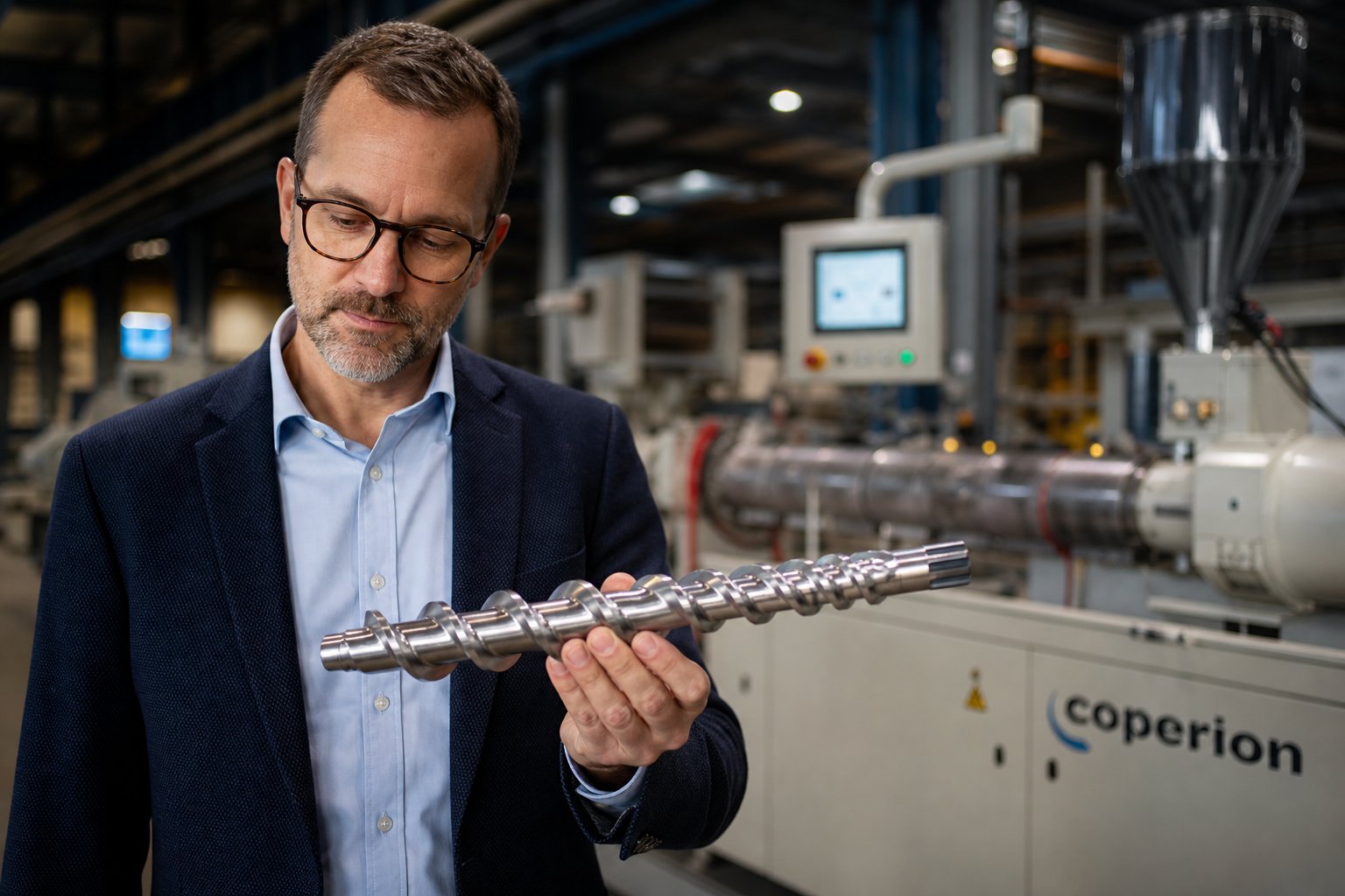
Matching Twin Screw Extruder Specifications to Your Processing Goals
You have the geometric fundamentals, the mechanical relationships, the application mapping, and the mistake checklist. What remains is assembling those pieces into a repeatable decision process - a structured workflow that moves from raw processing requirements to a fully defined machine specification, whether you are evaluating twin screw extruders for a new compounding line or upgrading an existing plastic twin screw extruder installation.
Building Your Specification Requirements Checklist
Walk through the following steps in order. Each one builds on the previous, and skipping ahead - say, jumping to screw diameter before clarifying your processing functions - almost always leads to backtracking later.
- Define target materials and formulations. Document every polymer, filler, additive, and reinforcement in your product portfolio. Include viscosity characteristics, thermal sensitivity limits, and abrasiveness. This data drives nearly every downstream specification decision.
- Establish throughput and output quality requirements. Set realistic production targets in kg/hr based on market demand and growth projections. Specify quality parameters - melt temperature tolerance, dispersion standards, volatile content limits - that constrain how aggressively you can push throughput.
- Identify required processing functions. Map every unit operation your process demands: solids conveying, melting, dispersive mixing, distributive mixing, liquid injection, side-feeding of fillers or fibers, atmospheric venting, vacuum devolatilization, and pressure buildup. Each function occupies barrel real estate.
- Calculate minimum L/D ratio based on functional zone requirements. Allocate 4D of barrel length per processing zone. Add one to two segments of margin. This gives your minimum L/D ratio - the architectural foundation for everything else.
- Evaluate torque and power requirements for target materials. Use specific energy input (SEI) benchmarks for your material family to estimate the motor power needed at your target throughput. Verify that the gearbox torque density supports sustained operation at 80% of continuous capacity with your most demanding formulation.
- Match screw diameter to throughput and torque needs. Cross-reference your throughput target with the free volume and torque capacity trade-offs governed by the Do/Di ratio. A twin screw plastic extruder rated for your throughput with an unfilled polymer may be torque-limited with your actual 45% filled compound.
- Specify barrel and screw element metallurgy for wear and corrosion resistance. Select liner materials and screw element coatings based on your compound's abrasiveness and corrosiveness - not the default options. PM-HIP alloys or tungsten carbide for glass-filled materials; corrosion-resistant bimetallic linings for halogenated compounds.
- Consider scale - lab, pilot, or production. If you are developing a new formulation, start at the smallest scale that provides meaningful data. Maintain geometric similarity (Do/Di ratio, screw element style) across scales to ensure reliable process transfer.
This sequence works because each step constrains the next. Material properties narrow the configuration choices. Processing functions set the minimum barrel length. Throughput and torque requirements lock the diameter range. Metallurgy ensures the machine survives contact with your actual formulation rather than failing prematurely against abrasive fillers or corrosive additives.
When to Consult Custom Screw Design Expertise
Completing this checklist gets you to the right base machine - the correct twin screws, barrel layout, motor, and gearbox combination for your application. But as every experienced compounder knows, the base machine is only the platform. The screw configuration running inside that platform determines whether you achieve target dispersion quality, hit your SEI window, or struggle with undertreated melt and excessive scrap.
Even with perfectly matched machine specifications, achieving optimal processing outcomes often requires custom screw geometry tailored to the specific polymer system, filler package, and output targets. The arrangement of conveying elements, kneading block stagger angles, mixing element types, and reverse-pumping sections must be engineered around how your material actually behaves under shear and heat - not around generic assumptions. As NC State Extension research emphasizes, configuring a screw profile is a blend of art and science because every material exhibits unique flow properties influenced by temperature, shear rate, and extruder geometry.
This is where specialized engineering support delivers measurable value. NANHAIYA's Custom Screw Design Services provide extrusion engineers and production teams with screw geometry recommendations, material selection guidance, and processing parameter optimization matched to specific polymers, machine conditions, and throughput requirements. Rather than defaulting to a general-purpose screw layout, their application-driven approach designs element sequences around documented material behavior - the kind of tailored engineering that closes the gap between what the machine specifications promise and what the production line actually delivers.
Selecting the right specifications is only half the equation - optimizing screw design for your specific material and process conditions turns specifications into performance.
Twin screw extruders are engineered platforms with extraordinary flexibility. The specifications decoded throughout this guide - from Do/Di ratio and torque density to barrel zone configurations and specific energy input - define the boundaries of what each machine can do. Your job is to match those boundaries to your process. The screw designer's job is to unlock the performance within them. Get both right, and the spec sheet stops being a document and starts being a production asset.
Frequently Asked Questions About Twin Screw Extruder Specifications
1. What is the most important specification when selecting a twin screw extruder?
No single specification determines success alone - the answer depends on your application. For filled compound processing, gearbox torque density (measured in Nm/cm3) is typically the limiting factor, because high filler loadings place enormous mechanical demands on the screw shafts. For reactive extrusion, L/D ratio takes priority since chemical reactions need sufficient residence time. For profile extrusion, pressure generation capability matters most. The key is matching priority specifications to your specific process demands rather than chasing headline numbers like maximum throughput or motor power in isolation.
2. What does the Do/Di ratio mean on a twin screw extruder spec sheet?
The Do/Di ratio is the outer screw diameter (Do) divided by the inner or root diameter (Di). It governs a fundamental trade-off between free volume and torque capacity. A higher ratio (e.g., 1.71 to 1.80) creates deeper screw channels with roughly 40% more free volume for higher throughput but reduces the shaft cross-section available for torque transmission. A lower ratio (e.g., 1.46 to 1.55) provides a larger shaft for high-torque applications like engineering plastic compounding but sacrifices volumetric intake capacity. Selecting the right Do/Di ratio requires balancing your material's viscosity, filler loading, and throughput targets against the torque demands of your formulation.
3. How do co-rotating and counter-rotating twin screw extruder specifications differ?
Co-rotating extruders operate at higher speeds (up to 1200+ RPM), feature strong self-wiping behavior, and excel at dispersive and distributive mixing for compounding and reactive extrusion. Counter-rotating designs run at lower speeds, generate higher die pressure through positive-displacement C-shaped chambers, and use a gentler calendering mixing mechanism ideal for heat-sensitive materials like PVC. Co-rotating machines typically offer wider L/D ratios (32:1 to 52:1) and greater screw element modularity, while counter-rotating units prioritize consistent melt delivery and pressure stability for profile and pipe extrusion applications.
4. What L/D ratio do I need for my twin screw extrusion process?
The required L/D ratio depends on how many functional processing zones your application demands. Each zone - solids conveying, melting, mixing, venting, side-feeding, or pressure buildup - typically occupies one 4D-length barrel segment. A simple color masterbatch process might need only 28:1 to 32:1, while a complex compounding operation with vacuum devolatilization and downstream fiber feeding often requires 40:1 to 48:1. Reactive extrusion processes may push to 52:1 or beyond. Map every required unit operation, allocate barrel segments accordingly, add one to two segments of margin, and that calculation yields your minimum L/D ratio.
5. Can I scale up twin screw extruder process data directly from lab to production equipment?
Not directly. Volumetric capacity scales with the cube of screw diameter (D3) while heat transfer surface area scales with the square (D2). This geometric mismatch means barrel temperature control becomes less effective at larger diameters, and a process running perfectly on a 16 mm lab extruder may overheat on a 70 mm production machine at identical setpoints. For reliable scale-up, maintain geometric similarity by matching Do/Di ratio and screw element style between machines, target the same specific energy input (kWh/kg), and expect to re-optimize barrel temperatures and screw speed independently. Working with a custom screw design specialist like NANHAIYA can help bridge the gap between lab-validated parameters and production-ready screw configurations.
Written by
Nanhaiya Technical Team
Zhoushan Nanhaiya Plastic Machinery Co., Ltd.
The Nanhaiya technical team supports screw and barrel manufacturing projects through application review, technical communication, custom manufacturing coordination, and production and quality control.
Discuss Your Application
Related Articles
More insights on screw barrel technology and plastics processing.

What Nobody Tells You About Screw Barrel For Plastic Machine Design
Oct 10, 2026
Learn how screw barrel for plastic machine design affects melt quality, throughput, and wear life. Covers geometry, resin matching, troubleshooting, and sourcing.
Read Article
Single Screw Extruder for Sheet: Stop Guessing, Start Specifying
Oct 9, 2026
Learn how to specify a single screw extruder for sheet production. Covers screw geometry, resin-specific processing, troubleshooting, and maintenance best practices.
Read Article
PE Pipe Extruder Machine: What Datasheets Won't Tell You
Oct 9, 2026
Learn how a PE pipe extruder machine works, key specs explained, material grade selection, maintenance tips, and buyer guidance beyond the datasheet.
Read ArticleLooking for something else?
Search by material, symptom or product and jump straight to the relevant page.
These are navigation suggestions based on keyword matching — not a quotation, not a delivery commitment, and not a substitute for engineering review. Final specification is confirmed by our engineers against your drawings and processed material.
Need help with screw barrel selection?
Share your machine model, processed material and application. Our team can help with pricing and technical support.