

What Is a PVC Pipe Extruder and How Does It Work
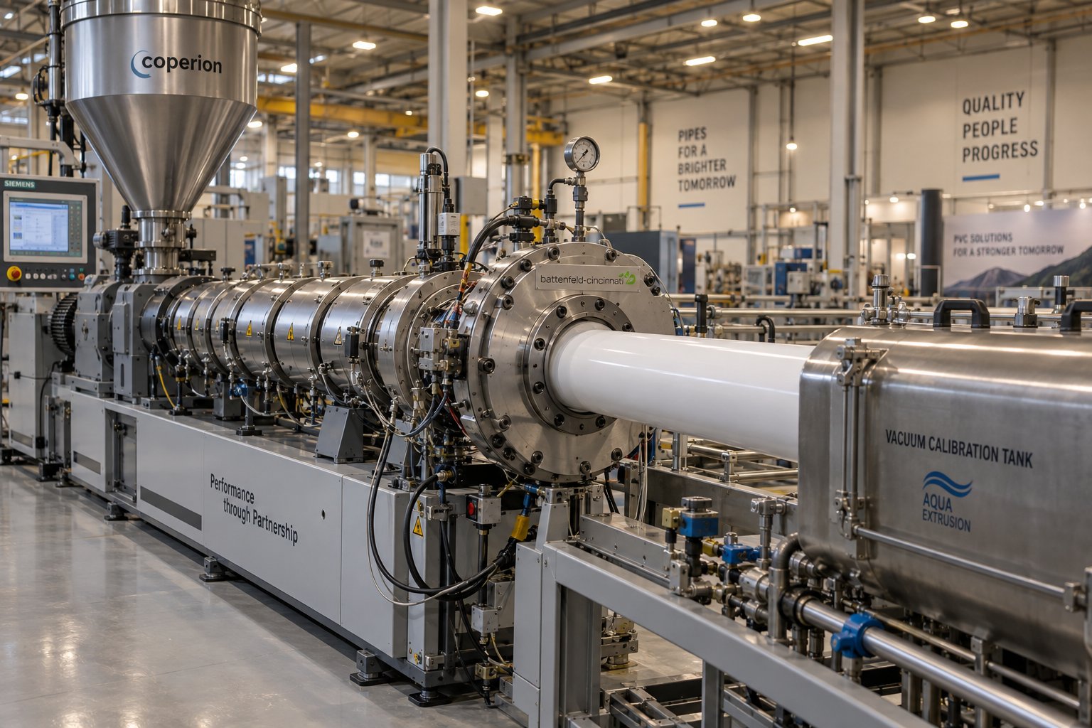
A PVC pipe extruder is a thermoplastic processing machine that melts, homogenizes, and shapes polyvinyl chloride compound into continuous pipe profiles by forcing material through a heated barrel-and-screw system and a calibrated die. While this description sounds similar to any plastic extruder, here is the critical distinction: PVC is one of the most thermally sensitive commodity plastics in production, and that single fact drives almost every design decision that separates a purpose-built PVC pipe extruder from a general-purpose machine.
PVC degrades close to the temperature it needs to flow. Most thermoplastics tolerate a generous band between "not yet melted" and "overheating." PVC does not. That narrow margin means the barrel geometry, screw profile, temperature control, and residence time inside the machine all require tighter engineering than what you'd find on a polyethylene or polypropylene line. If any of those variables drift, the result is discoloration, hydrochloric acid release, and compromised pipe strength.
What a PVC Pipe Extruder Actually Does
Imagine feeding a carefully prepared PVC dry-blend powder — or, in some cases, pre-compounded pellets — into a hopper that sits above a long heated barrel. Inside that barrel, one or two rotating screws convey the material forward, compress it, generate frictional heat, and push a uniform molten stream toward a pipe-shaped die at the far end. The pipe extrusion process explained in its simplest form is really about controlling four things simultaneously: forward movement, pressure, temperature, and mixing uniformity.
Every screw-based extruder divides its barrel into functional zones, and each zone plays a specific role for PVC processing:
- Feed zone: The screw channel depth remains constant here, drawing dry-blend or pellets from the hopper and conveying them forward. For PVC, consistent feeding is essential because irregular material flow creates temperature spikes and pressure fluctuations downstream.
- Compression (transition) zone: The channel depth decreases, compacting the material and squeezing out trapped air. This is where PVC begins to plasticize. The compression ratio must be carefully matched to PVC's shear sensitivity — too aggressive, and localized overheating triggers degradation.
- Metering zone: Channel depth stabilizes at its shallowest point, building consistent pressure to push the homogenized melt through the die. Uniform output from this zone directly determines wall thickness consistency in the finished pipe.
PVC has one of the narrowest processing windows of any commodity thermoplastic — it begins softening around 100°C yet starts releasing corrosive hydrochloric acid gas above roughly 210°C. This tight margin makes extruder design not just important, but mission-critical.
Where PVC Pipe Extruders Fit in the Manufacturing Landscape
PVC pipe accounts for a significant share of global plastic pipe demand, serving water supply networks, drainage systems, electrical conduit, and agricultural irrigation. Its combination of chemical resistance, long service life, and relatively low material cost keeps it dominant across infrastructure projects worldwide.
When you start evaluating equipment for this market, you'll encounter three primary extruder configurations: single-screw, parallel twin-screw, and conical twin-screw machines. Each handles PVC differently — and the right choice depends on whether you're processing rigid powder blends, flexible pre-compounded pellets, or filled specialty formulations. The differences run deeper than most equipment brochures suggest, touching material science, shear mechanics, and long-term economics in ways that shape both pipe quality and production cost.
Single-Screw vs Twin-Screw Extruders for PVC Pipe Production
Choosing between a single-screw and twin-screw extruder for PVC pipe isn't a matter of brand preference or budget alone — it's a material-science decision. PVC's thermal sensitivity, powder form, and shear behavior dictate which screw architecture can safely and efficiently turn raw compound into a consistent pipe profile. Get this choice wrong, and you'll fight degradation, inconsistent wall thickness, and excessive scrap for the life of the machine.
Most equipment comparisons stop at a bullet-point list. That's not enough when you're committing to a production line that needs to run reliably for a decade or more. The real question is: why does the polymer itself favor one design over another?
Why Rigid PVC Favors Twin-Screw Extrusion
Unplasticized PVC — often labeled UPVC or RPVC — is processed directly from dry-blend powder rather than pre-compounded pellets. That powder is light, has low bulk density, and tends to slip against smooth metal surfaces. A single-screw extruder relies on friction between the material and the barrel wall to push material forward. When the feedstock is a fine, slippery powder instead of dense granules, that friction-dependent conveying mechanism struggles. The result is inconsistent intake, fluctuating melt pressure, and uneven output — none of which you can afford when holding tight dimensional tolerances on pipe.
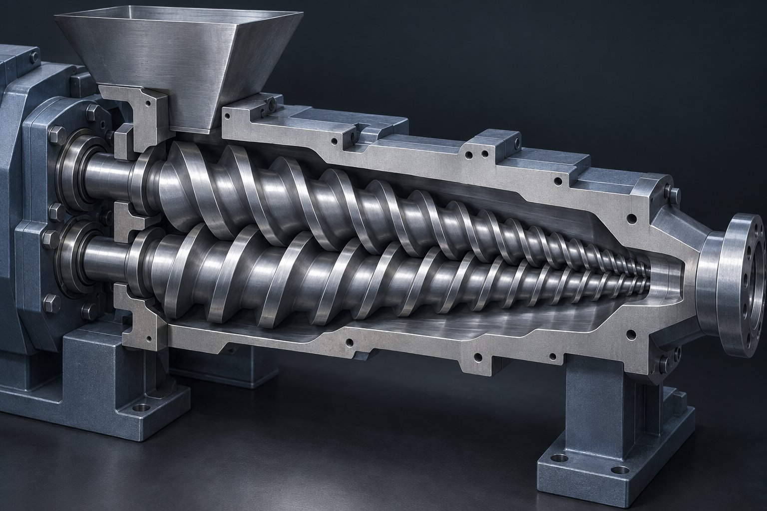
Twin-screw extruders solve this with a fundamentally different transport mechanism. Two intermeshing screws create enclosed, C-ring-shaped chambers that physically carry material forward through positive displacement rather than relying on barrel friction. This forced conveying works regardless of how slippery or low-density the feedstock is, which is exactly why twin-screw designs dominate rigid PVC pipe production worldwide.
The conical twin-screw extruder takes this advantage further with tapered geometry. Picture two screws that are wide at the feed end and narrow at the discharge end. That taper accomplishes two things simultaneously:
- High torque at the feed end: The larger screw diameter where powder enters provides the mechanical leverage needed to grab and convey low-bulk-density dry-blend without stalling.
- Controlled shear at the discharge end: As the screws narrow, the channel volume shrinks, progressively compressing and plasticizing the PVC with precisely managed shear — enough to melt it uniformly, but not so much that localized overheating triggers degradation.
There's another critical benefit. The intermeshing, counter-rotating screws in a conical twin-screw extruder create a self-wiping action. Each screw flight continuously cleans material off the other screw's surface, preventing stagnant pockets where PVC could sit at temperature and degrade. As noted in the reference data from Rollepaal, this self-wiping design also reduces the amount of heat stabilizer required in the formulation — a meaningful cost saving on every kilogram of compound processed. The narrow spread in residence time further ensures that every particle of PVC spends roughly the same duration inside the barrel, producing a more homogeneous melt and more consistent pipe properties.
When Single-Screw Extruders Make Sense for PVC
Does this mean single-screw machines have no role in PVC pipe production? Not entirely — but their sweet spot is narrower than many suppliers suggest.
Single-screw extruders can work well for plasticized (flexible) PVC, where the compound has already been pre-mixed with plasticizers and formed into pellets. Pelletized material is denser, flows more predictably, and doesn't suffer from the wall-slip issues that plague dry-blend powder on a single screw. In this scenario, the simpler, friction-based conveying mechanism performs adequately because the feedstock cooperates.
The trade-offs are worth understanding clearly:
- Lower capital cost: A single-screw machine is mechanically simpler — one screw, one barrel bore, a less complex gearbox — so the upfront investment is lower.
- Less mixing capability: Without the intermeshing, self-wiping action of twin screws, single-screw designs rely more heavily on barrel heating to melt the PVC rather than distributed shear. This can create less uniform melt temperatures across the cross-section.
- No positive conveying of powder: Attempting to run dry-blend PVC powder through a single-screw extruder typically requires a pre-granulation step, adding equipment cost and an extra thermal history to the material — which is a concern for a polymer that degrades cumulatively with each heat exposure.
- Wider residence time distribution: Material near the barrel wall and material near the screw root travel at different speeds, broadening the range of time particles spend at elevated temperature. For heat-sensitive PVC, this increases the risk of localized degradation.
In short, if your production plan centers on rigid PVC pipe from dry-blend — which represents the vast majority of PVC pipe manufacturing — a twin-screw extruder is not just preferred; it's practically essential.
Parallel vs Conical Twin-Screw Configurations
Knowing you need a twin-screw machine still leaves an important fork in the road: conical or parallel? Both use two intermeshing screws, but the geometry pushes each design toward different strengths. A conical twin-screw extruder features tapered screws that deliver high torque and strong compression in a compact barrel length, making it the standard for direct PVC pipe, profile, and board extrusion. A parallel twin-screw extruder uses constant-diameter screws along a longer barrel, providing extended mixing zones better suited for compounding, pelletizing, and dispersing very high filler loads.
The following table lays out the practical differences across the dimensions that matter most when selecting a PVC pipe extruder:
| Feature | Single-Screw Extruder | Parallel Twin-Screw Extruder | Conical Twin-Screw Extruder |
|---|---|---|---|
| PVC Form Handled | Pellets (pre-compounded) | Powder or pellets | Dry-blend powder (primary) |
| Conveying Mechanism | Friction-dependent | Positive displacement | Positive displacement |
| Shear Control | Limited; relies on barrel heat | Good; adjustable via L/D and screw elements | Excellent; progressive compression via taper |
| Torque Capacity | Moderate | High (constant along length) | Very high at feed end (large diameter) |
| Self-Wiping Action | No | Yes | Yes |
| Typical Pipe Diameter Range | Small-diameter flexible PVC | Medium to large (varies by model) | 16 mm up to 400+ mm (model-dependent) |
| Best Application Fit | Flexible PVC pipe and tubing | Compounding, pelletizing, high-filler PVC | Rigid PVC pipe, profile, board, WPC |
| Energy Efficiency | Moderate (more barrel heating needed) | Good (long mixing zones reduce external heat) | Good (internal shear heat reduces heater load) |
| Capital Cost Range | Lowest | Higher | Mid-to-high (less than parallel for same output class) |
A practical rule of thumb from manufacturers who build both configurations: choose conical for direct PVC pipe and profile extrusion, and lean toward parallel when your primary task involves compounding, masterbatch production, or dispersing very high calcium carbonate filler loads. Many established pipe plants run conical twin-screw machines as their production backbone, while compounding operations and WPC pelletizing lines tend to favor parallel designs.
The extruder architecture you select ripples through every downstream decision — die design, cooling capacity, haul-off speed, and even the metallurgy of the screws and barrel themselves. Those technical specifications deserve their own close examination, because the numbers on a datasheet determine whether a machine merely runs or truly performs.
Critical Technical Specifications That Define Extruder Performance
Datasheet numbers can look like alphabet soup — screw diameters listed as fraction pairs, L/D ratios that seem arbitrary, and output capacities that vary wildly between models with similar price tags. Yet these specifications are the DNA of your PVC pipe extruder. They determine melt quality, energy draw, maximum pipe size, and how forgiving the machine will be when your formulation or ambient conditions shift. Understanding what each number actually controls turns a confusing spec sheet into a decision-making tool.
Screw Diameter and L/D Ratio Explained
If you've looked at conical twin-screw extruder specifications, you've noticed the unusual diameter notation — something like 51/105 mm or 65/132 mm or 80/156 mm. Those two numbers aren't interchangeable sizes. The first figure is the screw diameter at the discharge (small) end, and the second is the diameter at the feed (large) end. That taper is the defining feature of a conical design, and the size pairing tells you immediately how much mechanical leverage the machine can generate at intake versus how tightly it compresses material before the die.
Smaller conical pairs like 51/105 mm are workhorses for pipes in the range of roughly 16–110 mm diameter. Step up to a 65/132 mm configuration and you're covering medium-diameter pipes, while 80/156 mm and larger machines handle heavy-wall pipes at 315 mm and above. Each jump in screw diameter brings proportionally higher torque, greater volumetric throughput, and a bigger motor to drive it all.
Then there's the L/D ratio — the length of the screw relative to its diameter. For conical twin-screw machines processing rigid PVC, you'll typically see L/D values in the range of 20:1 to 22:1 for straightforward pipe production. Why does this matter? A longer screw gives the PVC more time under controlled shear and heat, which improves melt homogeneity. Shorter ratios are sufficient for standard UPVC dry-blend formulations where the compound melts readily. Longer ratios — pushing toward 26:1 or beyond — come into play when you're running heavily filled PVC compounds (high calcium carbonate loading, for instance) or foamed PVC formulations that need extra mixing to distribute blowing agents uniformly.
A word of caution: these numbers represent general industry ranges. Actual specifications vary between manufacturers, and confirming exact values against the relevant datasheet for a specific model is essential before making purchasing or process-setup decisions.
Output Capacity, Motor Power, and Screw Speed Ranges
How much pipe can a machine produce per hour? The answer scales directly with screw diameter — but not in a simple linear relationship. A larger screw moves more material per revolution, and larger barrels accommodate higher throughput before melt quality begins to suffer. As a practical reference, manufacturer-rated throughput data shows that a 50 mm class extruder typically delivers around 40–90 kg/h for PVC, while a 100 mm class machine reaches 320–640 kg/h. Larger-diameter screws in the 150 mm range can push 800–1,600 kg/h under optimal conditions.
Motor power follows a similar escalation. Smaller conical twin-screw extruders may require drive motors in the 15–37 kW range, while mid-size machines climb to 55–90 kW, and large-diameter units demand well over 100 kW. The critical insight here is that motor power and screw speed must be evaluated together, not in isolation. A high-power motor running at moderate RPM delivers different results than a smaller motor pushed to its speed limit.
Speaking of speed — PVC pipe extruders operate at significantly lower screw speeds than machines designed for polyolefins. Where a polyethylene extruder might run screws at 150–300 RPM, a PVC pipe extruder typically operates between 15 and 45 RPM for conical twin-screw designs. Why so slow? Every RPM increase generates additional frictional heat inside the barrel. Data on RPM-temperature relationships shows that even a 10% speed increase can raise melt temperature by 3–5°C. For a polymer that degrades rapidly above approximately 210°C, that seemingly modest temperature bump can push a borderline process into degradation territory — producing yellowed pipe, HCl off-gassing, and compromised mechanical strength.
The practical takeaway: never chase higher output by simply cranking up screw speed. If your current machine can't meet production targets at safe RPM ranges, the issue is likely undersized screw diameter — not insufficient speed.
Barrel Zone Temperature Profiles for PVC
A PVC pipe extruder barrel is divided into distinct heating zones — typically four to six — each independently controlled by its own heater band and thermocouple. This isn't an optional refinement; it's a necessity driven by PVC's degradation sensitivity. The material must reach a uniform melt state without any single zone overshooting the thermal ceiling.
PVC processing temperatures generally range from approximately 160°C to 200°C, depending on the compound formulation and zone position. The feed zone runs cooler to prevent premature melting that would block powder flow. Temperatures rise progressively through the compression and metering zones as the material plasticizes. The die zone is often held at a slightly elevated temperature to ensure smooth melt flow and a clean pipe surface. Each zone serves a distinct purpose, and the table below provides a representative baseline profile for rigid PVC pipe extrusion on a conical twin-screw machine:
| Barrel Zone | Representative Temperature Range | Primary Purpose |
|---|---|---|
| Zone 1 (Feed) | 155–165°C | Gently preheats incoming powder without premature fusion; maintains free-flowing feed intake |
| Zone 2 (Early Compression) | 165–175°C | Begins compacting and plasticizing the PVC as screw channel depth decreases |
| Zone 3 (Late Compression) | 170–185°C | Completes fusion; most frictional shear heat is generated here, so external heat input may be reduced |
| Zone 4 (Metering) | 175–190°C | Stabilizes melt temperature and pressure for consistent output to the die |
| Adapter / Connector | 180–195°C | Maintains melt flow consistency during transition from barrel to die |
| Die Zone | 185–200°C | Ensures smooth surface finish and uniform flow distribution across the pipe cross-section |
These values are representative guidelines — not universal settings. Your specific PVC formulation, stabilizer package, filler content, and even ambient shop temperature will require adjustments. What stays constant is the principle: feed zone temperatures must remain low enough to prevent bridging, and no zone should approach or exceed the material's degradation threshold. A 5°C overshoot in the wrong zone can turn an entire production run into scrap.
You'll also notice something counterintuitive in well-running PVC lines: the heater bands in the compression and metering zones often cycle off during steady-state operation. That's because the shear heat generated by the twin screws provides a substantial portion of the energy needed to plasticize PVC. The barrel heaters in those zones shift from heat sources to temperature regulators — sometimes even requiring cooling — to prevent the internally generated frictional heat from exceeding safe limits. This interplay between mechanical and thermal energy is one of the reasons why PVC extrusion demands such precise zone-by-zone control, and it's exactly why the material's unique processing behavior drove the specialized machine engineering explored in the next section.
Why PVC Demands Specialized Extruder Engineering
Barrel temperatures, screw speeds, zone profiles — they all point back to the same underlying reality: PVC is not a forgiving polymer. Every design choice discussed so far exists because of specific material properties that make polyvinyl chloride one of the most challenging thermoplastics to process. Understanding those properties at the molecular level transforms extruder selection from a catalog exercise into an engineering decision grounded in chemistry and physics.
So what exactly makes PVC so difficult? Three interrelated challenges — a dangerously narrow thermal window, acute shear sensitivity, and corrosive-plus-abrasive processing conditions — converge to create demands that no general-purpose extruder can safely handle.
PVC's Narrow Thermal Processing Window
Most commodity thermoplastics offer generous headroom between melting and degradation. Polyethylene, for instance, melts around 130°C and remains thermally stable well past 300°C. PVC operates in a completely different reality. It begins to soften around 100°C, reaches a processable melt state between 170–200°C, and starts releasing hydrochloric acid (HCl) gas above roughly 210°C. That gives engineers an effective PVC processing window of barely 30–40°C within which to fully plasticize the compound without triggering decomposition.
When degradation does occur, it's not a subtle event. Thermal decomposition of PVC initiates a chain reaction called dehydrochlorination — the polymer backbone sheds HCl molecules in a cascade that accelerates once it starts. The visible consequences include yellowing or brown discoloration, black specks embedded in the pipe wall, and a sharp, acrid odor at the die exit. The mechanical consequences are equally severe: degraded PVC loses impact strength, becomes brittle, and fails pressure testing. And the equipment consequences are costly — HCl gas is highly corrosive, attacking barrel surfaces, screw flights, and downstream tooling with every degradation event.
This tight PVC thermal degradation temperature range drives three non-negotiable extruder design requirements:
- Precise barrel temperature control: Independent zone heating with responsive PID controllers must hold each barrel section within a few degrees of its setpoint. A 5°C overshoot that would be inconsequential when processing polypropylene can push PVC into active decomposition.
- Optimized screw compression ratios: As screw design engineering data confirms, PVC requires compression ratios in the range of 1.6:1 to 2.2:1 — far lower than the 3.0:1 to 4.0:1 typical for polyolefins. A gentler compression gradient limits the frictional heat spike during the transition from powder to melt, keeping the material within its safe processing band.
- Minimal residence time: Every second PVC spends at elevated temperature accumulates thermal damage. Short L/D ratios (typically 20:1 to 24:1), combined with the positive-displacement conveying of twin-screw designs, ensure the material moves through the barrel quickly and uniformly — no stagnant pockets, no hot spots, no lingering.
Think of it this way: processing polyethylene is like cooking with a wide temperature dial that offers plenty of room between "done" and "burned." Processing PVC is like working under a heat lamp where five degrees too high scorches the product and poisons the equipment. The extruder has to function as a precision thermal instrument, not just a melting machine.
Shear Sensitivity and Compression Ratio Design
Temperature isn't the only threat. PVC is equally sensitive to mechanical energy — the shear forces generated as the screw pushes, compresses, and mixes the material. In a PVC pipe extruder, 70–80% of the energy needed to plasticize the compound comes from internal shear friction rather than external barrel heaters. That makes screw geometry the primary temperature control mechanism, whether the machine designer intended it or not.
Here's where PVC shear sensitivity screw design becomes critical. The screw's compression ratio, flight depth, and channel geometry determine how much frictional heat the material absorbs per revolution. A shallow metering channel forces polymer through a tighter gap, dramatically increasing local shear rate and viscous dissipation. For polyethylene, that extra shear might raise melt temperature a few degrees — well within the polymer's tolerance. For PVC, the same geometry can push localized temperatures past 210°C in the metering zone, triggering the degradation cascade described above — even when every barrel zone thermocouple reads safely below the setpoint.
This is precisely why PVC screw designs use deeper metering channels — typically 3.5 to 5.0 mm, compared to 2.5 to 3.5 mm for polyolefins of similar screw diameter. The deeper channel reduces shear intensity per unit of material, spreading mechanical energy input more gently across the melt cross-section. It also explains why barrier flights — the secondary helical flights used so successfully in polyethylene extrusion to prevent solid bed breakup — are generally avoided for rigid PVC. Barrier flights add shear through the tight clearance over the barrier land, and that additional mechanical energy input exceeds what PVC can tolerate.
Twin-screw extruders handle this balancing act far better than single-screw designs for rigid PVC. The intermeshing, counter-rotating screws distribute shear across two parallel channels rather than concentrating it in one. The self-wiping action ensures no material sits in a high-shear zone longer than its neighbors, creating a narrow residence time distribution. And the conical taper geometry progressively increases compression rather than imposing it in a single aggressive transition zone — effectively spreading the shear energy budget over a longer portion of the barrel length.
The result? A more uniform melt temperature with fewer localized hot spots — the single most important factor in preventing PVC degradation during extrusion.
Corrosion and Abrasion Challenges
Even under ideal processing conditions, PVC releases trace amounts of HCl during normal extrusion. Add the reality that most PVC pipe formulations contain abrasive mineral fillers — calcium carbonate at loadings of 5–15 parts per hundred, titanium dioxide for UV resistance, or chalk for cost reduction — and the barrel and screw face a punishing dual assault: chemical corrosion and mechanical abrasion happening simultaneously on every production run.
Standard nitrided steel barrels and screws, which perform perfectly well for unfilled polyolefins, deteriorate rapidly under these conditions. The nitrided surface case — typically hardened to 55–70 HRC — resists abrasive wear reasonably well, but offers limited defense against acid attack. HCl penetrates microscopic surface imperfections, initiating corrosive pitting beneath the hardened layer. Once pitting begins, it accelerates: each pit creates a stagnation point where more PVC degrades, generating more HCl, and deepening the corrosion. Meanwhile, abrasive filler particles grind against flight tips and barrel bore, steadily widening the clearance between screw and barrel. That growing gap reduces conveying efficiency, increases melt leakage, and destabilizes output pressure — all of which show up as inconsistent pipe wall thickness.
This is why a bimetallic barrel for PVC extrusion isn't a premium upgrade — it's a baseline requirement for serious production. Bimetallic centrifugal-cast barrel linings, typically based on nickel-rich boron alloys with molybdenum, boride, and carbide components, provide the acid resistance needed to withstand HCl exposure while maintaining hardness sufficient to resist filler abrasion. On the screw side, hardfacing alloys like Colmonoy 56 or tungsten-carbide coatings protect flight tips and root surfaces from both wear mechanisms simultaneously.
One subtlety that experienced PVC processors watch closely: thermal expansion mismatch. Corrosion-resistant alloys often have different coefficients of thermal expansion than standard barrel steels. If the screw and barrel metallurgies aren't matched as a system, the flight-to-barrel clearance shifts as operating temperatures climb — potentially tightening to the point of metal-to-metal contact and catastrophic scoring, or loosening to the point of excessive leakage. Screw and barrel materials must be specified together, not independently.
Taken as a whole, these PVC processing window extruder requirements create a clear picture of why purpose-built equipment matters. The following list summarizes the key material properties of PVC that directly influence extruder design decisions:
- Narrow thermal processing window (~170–210°C usable range) — demands precise multi-zone temperature control and low compression ratios
- Dehydrochlorination above ~210°C — releases corrosive HCl gas that attacks metallic components
- High shear sensitivity — requires deep metering channels, gentle compression gradients, and avoidance of barrier flights
- Powder feedstock (rigid PVC) — necessitates positive-displacement conveying via twin-screw designs rather than friction-dependent single-screw transport
- Abrasive filler content (CaCO3, TiO2) — demands hardened flight tips and wear-resistant barrel linings
- Cumulative thermal degradation — each heat exposure adds to the polymer's degradation history, making minimal residence time and uniform shear distribution essential
- Corrosion-abrasion synergy — simultaneous chemical and mechanical attack requires bimetallic barrel linings and matched screw metallurgy
These seven properties don't operate in isolation — they interact, amplify each other, and collectively explain why a PVC pipe extruder is engineered so differently from machines built for more forgiving polymers. Yet the extruder itself is only the central element in a much larger production system. The equipment surrounding it — from the feeder above the hopper to the stacker at the end of the line — determines whether that carefully engineered melt stream actually becomes a pipe worth shipping.
Anatomy of a Complete PVC Pipe Production Line
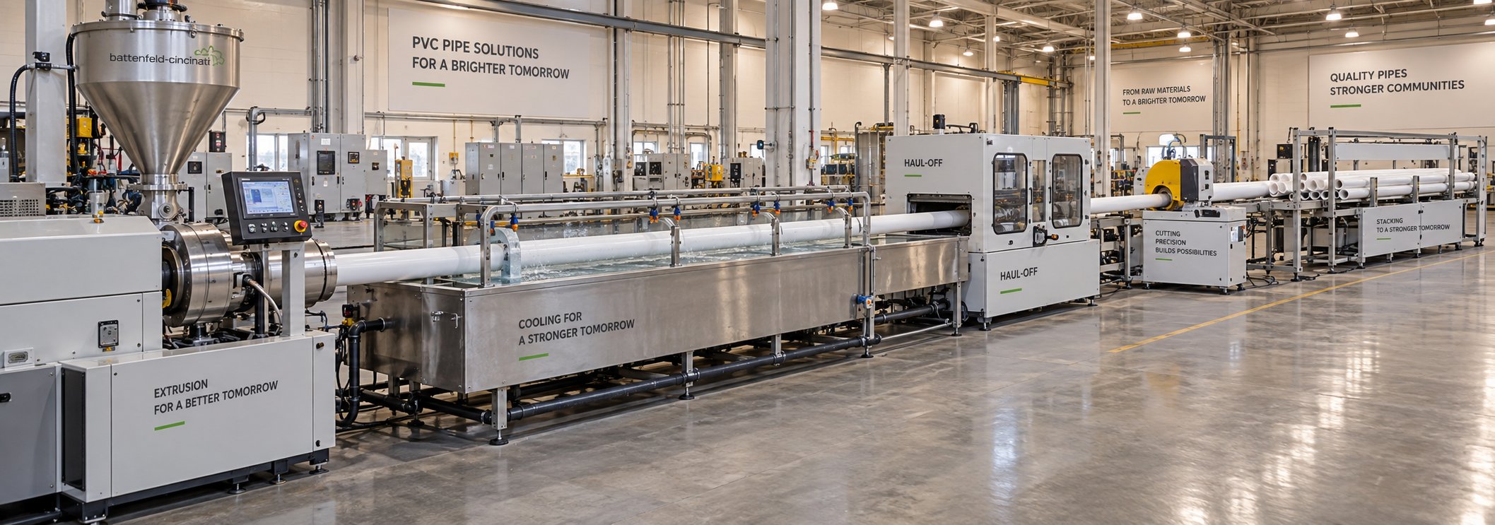
A perfectly tuned extruder means nothing if the feeder above it starves the screws or the haul-off downstream pulls the pipe at the wrong speed. Every PVC pipe extrusion line is a chain, and the weakest link — not the extruder alone — determines the quality of pipe that rolls off the end. Understanding each component's role, from raw material intake to finished pipe stacking, is essential for anyone specifying, operating, or troubleshooting a production line.
Think of it as a relay race. The extruder is the anchor leg, but the handoffs before and after it dictate whether the team wins or stumbles.
Upstream Equipment and Feeding Systems
Before PVC ever reaches the extruder barrel, it goes through preparation and dosing. Rigid PVC pipe production starts with a hot/cold mixer system — a high-intensity mixer that blends PVC resin with stabilizers, lubricants, fillers, and pigments at elevated temperature, followed by a cooling mixer that brings the dry-blend down to a safe storage temperature. The quality of this dry-blend — its particle size distribution, moisture content, and additive homogeneity — sets the ceiling for what the extruder can achieve downstream.
From the mixer, the dry-blend moves to a feeding system that meters material into the extruder hopper. This is where a decision that seems minor on paper — gravimetric vs volumetric feeder — has outsized impact on production economics and pipe quality over time.
Volumetric feeders meter material based on volume or auger speed. They're mechanically simpler and less expensive, making them a common choice for straightforward production runs. Their limitation? They assume the material's bulk density stays constant. If powder packing varies between batches — and with PVC dry-blend, it often does — the actual mass delivered per minute drifts. That drift shows up as subtle wall thickness variation in the finished pipe. Industry data from AEC places typical volumetric feeder accuracy in the range of 1.5% to 5%, depending on material consistency and feeder design.
Gravimetric feeders measure material by weight using load-cell technology and automatically adjust feed rates in real time to maintain a target. That continuous closed-loop correction delivers accuracy within approximately ±1% of the target feed rate. For PVC pipe producers, the practical benefit is tighter wall thickness control, which translates directly into material savings — you can target nominal wall thickness more confidently instead of building in extra "safety margin" that wastes compound on every meter of pipe. Over thousands of production hours, that margin compounds into significant raw material cost reduction.
As Rollepaal's optimization guidance highlights, gravimetrics and inline scanners integrated into the extrusion line help control material usage and wall thickness, reducing overweight and reject rates. The feeder's precision ripples through the entire line — consistent input volume means stable melt pressure, which means predictable pipe dimensions with fewer corrections needed at the die or haul-off.
Downstream Components from Die to Stacker
The extruder produces a continuous stream of homogenized PVC melt. Everything that happens after the barrel exit transforms that melt stream into a dimensionally accurate, cooled, cut, and packaged pipe. Here are the PVC pipe extrusion line components in their production sequence:
- Pipe die and mandrel — Shapes the circular melt stream into a hollow pipe profile. The die gap and mandrel position determine the pipe's outer diameter and wall thickness. Spider dies are common for PVC, using support legs to center the mandrel while allowing melt to flow around them.
- Vacuum calibration tank — Immediately after the die exit, the still-soft pipe enters a sealed tank where external vacuum pressure pulls the pipe's outer surface against a precision-machined sizing sleeve. This is where the pipe gets its final outer diameter and roundness. Simultaneously, cooling water begins solidifying the outer wall to lock in those dimensions. The PVC pipe vacuum calibration tank function is essentially a combined sizing-and-cooling station — without it, the pipe would sag, deform, or shrink unevenly as it cooled.
- Spray cooling tanks — One or more open tanks spray water over the pipe to continue cooling the wall through its full thickness. Longer pipes and thicker walls require additional cooling length. Uniform cooling matters: if one side of the pipe cools faster than the other, residual stresses build in and cause warping or ovality after cutting.
- Haul-off unit — A caterpillar-track or belt-driven pulling device that grips the cooled pipe and draws it through the entire downstream line at a precisely controlled speed. The haul-off speed, coordinated with extruder output, determines the pipe's final wall thickness and length per unit time. Speed fluctuations here translate directly into dimensional inconsistency.
- Cutting saw — A traveling saw (planetary or chip-free) cuts the continuously moving pipe to preset lengths without stopping the line. The saw carriage travels with the pipe during the cut, then returns to its starting position for the next cycle.
- Belling or stacking unit — Depending on the pipe's application, the cut length either passes to a belling machine (which heats and expands one end to create an integral socket joint) or to an automatic stacking and bundling system for packaging and storage.
Each component must be matched to the extruder's output rate and the target pipe specification. An undersized vacuum calibration tank, for example, can't cool a thick-walled pipe fast enough, forcing the line to slow down and sacrificing throughput that the extruder could otherwise deliver. The line speed is always governed by the slowest link — frequently the cooling section, not the extruder itself.
Matching Extruder Size to Pipe Specifications
One of the most practical questions buyers and engineers ask: which PVC pipe extruder size handles which pipe diameter range? The answer depends on the relationship between screw diameter, melt throughput, and the volume of material needed to form a given pipe cross-section.
As a general framework based on conical twin-screw configurations:
| Conical Twin-Screw Size Class | Approximate Pipe Diameter Range | Typical Application |
|---|---|---|
| 51/105 mm to 55/110 mm | 16–110 mm | Electrical conduit, small-diameter water supply, drainage fittings |
| 65/132 mm to 68/143 mm | 63–250 mm | Residential water and sewer pipe, medium-diameter drainage |
| 80/156 mm to 92/188 mm | 160–400+ mm | Municipal water mains, large-diameter sewer, industrial drainage |
These ranges are general guidelines, not absolute boundaries. Actual capability depends on the specific manufacturer's machine design, the PVC formulation's flow behavior, wall thickness requirements, and downstream line capacity. A 65/132 mm extruder might handle 315 mm pipe with thin walls, but struggle to deliver enough material for heavy-wall pressure pipe at that same diameter. Production engineering data confirms that conical twin-screw machines typically cover diameters from 16 mm up to approximately 630 mm, while pipes above 400 mm increasingly shift toward parallel twin-screw or large single-screw machines that can sustain the higher throughput volumes required.
The practical rule? Size the extruder so it operates at roughly 70–85% of its rated maximum output under normal production conditions. Running consistently at full capacity leaves no margin for batch-to-batch material variation, ambient temperature swings, or the gradual output decline that comes with normal screw and barrel wear. That wear — how it develops, how to detect it, and when to act on it — is one of the most expensive and least discussed aspects of owning a PVC pipe extrusion line.
Screw and Barrel Maintenance, Wear, and Replacement Strategy
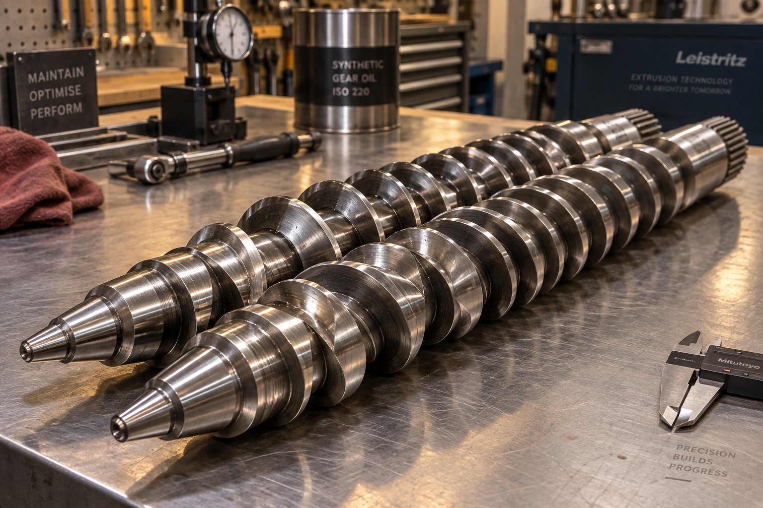
Screws and barrels don't fail suddenly — they decay gradually, draining efficiency in small increments that compound into major production losses long before anyone calls for a shutdown. In PVC pipe extrusion, this slow decline is uniquely punishing because the polymer itself accelerates the destruction. The corrosive HCl byproducts discussed earlier attack metal surfaces on every production run, while abrasive fillers like calcium carbonate and titanium dioxide grind away at flight tips and barrel bore simultaneously. Understanding how these wear mechanisms develop, what warning signs to watch for, and which metallurgical options extend service life is the difference between planned maintenance and emergency downtime.
Common Wear Patterns in PVC Pipe Extruder Screws and Barrels
PVC creates a dual wear mechanism that no other commodity thermoplastic replicates at the same intensity. According to Glycon Corp.'s screw and barrel analysis, three distinct wear types operate inside every plasticating unit — and PVC pipe extruders experience all three concurrently:
- Adhesive wear on screw flights occurs when metal-to-metal contact between the flight land and barrel wall creates localized welding and fracture. You'll spot it as burrs or "rolling over" of the trailing flight edge, or as scoring lines on the barrel bore at the corresponding axial position. Misalignment, screw deflection, or solids wedging from poor screw design amplifies this mechanism.
- Abrasive wear in the barrel bore concentrates in the compression and metering zones, where PVC compound under high pressure forces hard filler particles against the barrel lining and flight surfaces. Industry maintenance data confirms that calcium carbonate and titanium dioxide — the two most common fillers in rigid PVC pipe formulations — are among the primary abrasive agents that shorten barrel life. Highly filled compounds can reduce useful screw and barrel life by 50% or more compared to clean, unfilled PVC.
- Corrosive pitting caused by HCl concentrates at two vulnerable regions: the feed zone and the vent zone. These areas are cooler, which allows moisture from the PVC dry-blend, hygroscopic fillers, or humid shop air to condense on the metal surface. That condensate meets hydrogen chloride gas and forms concentrated hydrochloric acid pools that initiate pitting corrosion beneath the hardened surface layer. Once a pit forms, it creates a stagnation point where more PVC degrades, generating more acid — a self-reinforcing cycle that deepens the damage with every production hour.
The corrosion-wear synergy is what makes PVC uniquely destructive. Acid weakens the metal surface and exposes fresh, unpassivated material; then abrasive particles strip away that weakened layer far faster than they could remove intact, hardened metal. This synergy explains why a nitrided barrel running heavily filled PVC may fail in a fraction of the time it would last on clean polyethylene.
Recognizing wear before it reaches critical levels is the most valuable maintenance habit a PVC pipe plant can develop. The trouble is that degradation manifests slowly — operators adapt without realizing they're compensating for a deteriorating machine. Here are the key PVC extruder screw and barrel wear signs that indicate replacement is approaching:
- Rising melt temperature at the same RPM: As clearance between screw flights and barrel bore increases, more material leaks backward over the flights. The polymer is sheared repeatedly without advancing, generating excess heat. If your melt thermocouple reads progressively higher at constant screw speed without a formulation change, clearance growth is the likely culprit.
- Declining output rate: Worn flights can't convey material forward as efficiently. Operators instinctively compensate by increasing screw speed — which adds even more shear heat to an already overheating system. Clearance analysis shows that every additional 0.10 mm of clearance can reduce throughput by roughly 4–8% on mid-size machines, meaning a barrel worn to its discard threshold may already be producing 16–32% less than when new.
- Loss of melt pressure stability: Fluctuating head pressure at steady-state operation signals inconsistent metering — often from uneven wear patterns that create preferential flow paths within the screw channel.
- Deteriorating pipe dimensional tolerances: Wall thickness variation, ovality, and surface inconsistencies that weren't present when the machine was new point directly to worn screws that no longer homogenize the melt or maintain uniform output pressure.
- Increasing screw speed required for same output: This is the classic "creeping compensation" pattern. If your process log shows screw RPM climbing month over month to hold the same kg/h target, the screws are losing conveying efficiency.
- Visual evidence during screw pull: Rounded flight edges, scored or pitted surfaces, localized metal loss at flight tips, and discoloration from acid attack are all confirmation that clearance measurements alone might miss.
A disciplined plant logs drive current, melt pressure, output rate, and zone temperatures every shift. Plotting these values over weeks and months reveals wear trends that single-point readings miss entirely. The goal is to identify the "point of diminishing returns" — the threshold where machine adjustments can no longer compensate for wear — and schedule rebuilds before quality or throughput collapse forces an unplanned stop.
Bimetallic Barrel and Screw Alloy Options
Knowing that wear is inevitable shifts the question from "if" to "how long can I extend the interval?" The answer lies in metallurgy — matching the barrel lining and screw surface treatment to the specific PVC compound being processed.
Standard nitrided steel (38CrMoAlA) remains the entry-level option. Nitriding produces a hardened case of roughly 0.5–0.8 mm depth with surface hardness around HV 900–1000. For clean, lightly filled rigid PVC processed at moderate throughput, nitrided components deliver acceptable service life at the lowest initial cost. Their limitation becomes apparent with filled or recycled PVC — the acid attacks steel beneath or between micro-cracks in the nitride layer, and once that case is breached, the underlying metal erodes rapidly.
Bimetallic centrifugal-cast barrel linings represent the industry standard for any PVC pipe extruder running stabilized, filled compound. A nickel-based or cobalt-based alloy is spun into the barrel bore during manufacturing, forming a bonded wear layer approximately 1.5–2.5 mm thick with hardness in the HRC 58–65 range. Nickel-based linings offer superior acid resistance, making them the preferred choice for PVC's corrosive environment. Cobalt-based linings add higher heat resistance and suit extreme-output applications. As detailed maintenance literature confirms, a properly specified bimetallic barrel for a PVC pipe extruder outlasts a plain nitrided barrel by a wide margin under aggressive compounds.
Screw flight surface upgrades can be specified independently of the base screw material:
| Treatment | Hardness | Corrosion Resistance | Wear Resistance | Best Suited For |
|---|---|---|---|---|
| Nitriding (38CrMoAlA) | HV 900–1000 | Medium | Medium | Clean rigid PVC, low filler loading |
| Hard chrome plating | HV 800–1000 | Good | Low–Medium | Corrosion barrier, improved release |
| Bimetallic weld surfacing | HRC 55–62 | Good | Very Good | Flight tip protection on filled PVC |
| HVOF tungsten carbide | HV 1000+ | Excellent | Excellent | High filler, regrind, flame-retardant PVC |
The right material selection directly impacts replacement intervals and production consistency. A plant running one clean rigid PVC grade can specify nitrided screws with a bimetallic barrel at moderate cost and achieve multi-year service. A job-shop environment processing filled, plasticized, recycled, and flame-retardant PVC through the same machine should invest in HVOF tungsten-carbide screw coatings paired with a nickel-based bimetallic barrel — accepting the higher upfront cost for dramatically longer rebuild cycles. The key principle: match metallurgy to the compound, not to the lowest purchase price.
Choosing a Reliable Replacement Screw and Barrel Supplier
When wear measurements finally cross the rebuild threshold, the quality of replacement components determines whether you restore original performance or simply reset the clock on a shorter countdown. Sourcing a conical twin screw barrel replacement isn't like ordering a commodity spare — it's a precision fit that must integrate mechanically with your existing gearbox and thermally with your PVC formulation.
Here's what experienced manufacturers prioritize when evaluating a conical twin screw barrel replacement supplier:
- Dimensional precision: Replacement barrels must match the taper geometry, bore tolerance, and mounting interface of the original equipment. Even small deviations in bore diameter or taper angle change screw-to-barrel clearance, altering conveying efficiency and shear characteristics. Confirm that the supplier manufactures to your machine's specific drawing, not a generic approximation.
- Metallurgy matched to your PVC formulation: A supplier who asks detailed questions about your compound — filler type, filler loading, stabilizer system, processing temperature profile — before recommending an alloy is a supplier who understands PVC. One who offers a single "standard" lining for all applications is cutting corners that you'll pay for in shortened service life.
- PVC-specific production expertise: Screws and barrels for PVC extrusion face demands that polyolefin-focused suppliers may not fully appreciate — the corrosion-abrasion synergy, the tight clearance requirements for powder conveying, and the thermal sensitivity that punishes any geometry imprecision. Suppliers who specialize in PVC extrusion components deliver parts engineered for these specific challenges.
- Responsive production support: Downtime during a screw and barrel changeout is expensive. A supplier who maintains inventory of common conical twin-screw sizes, offers expedited manufacturing for custom specifications, and provides technical guidance on installation and break-in procedures reduces total downtime cost.
For PVC pipe, profile, board, and WPC extrusion applications, NANHAIYA's conical twin screw barrel line is worth evaluating in this context. They specialize specifically in custom and replacement conical twin screw barrels for PVC extrusion, offering tailored alloy options — including bimetallic linings — designed for stable plasticizing performance under corrosive and abrasive PVC processing conditions. Their focus on PVC-specific metallurgy and dimensional precision for gearbox compatibility addresses the exact sourcing criteria outlined above.
Regardless of which supplier you ultimately choose, establish a PVC extruder screw barrel maintenance schedule that includes regular clearance measurements — every six months for continuous production with filled compounds, or up to twelve months for stable single-grade rigid PVC lines. Track the clearance trend over multiple measurement cycles, and you'll develop a site-specific wear rate (in mm per thousand running hours) that lets you predict rebuild timing with confidence rather than guesswork. That predictive capability turns unplanned emergency stops into scheduled maintenance windows — and the cost difference between those two scenarios is substantial.
Healthy screws and barrels are the foundation, but even a perfectly maintained machine can produce defective pipe if process parameters drift. Surface roughness, wall thickness variation, and discoloration each trace back to specific extruder settings — and diagnosing the right root cause requires a systematic approach that connects symptoms to their mechanical and thermal origins.
Troubleshooting Common PVC Pipe Extrusion Defects
A pipe rolls off the haul-off with a surface that looks like sandpaper. Another batch shows wall thickness variation that drifts outside tolerance. A third run produces pipe with yellow streaks that fail quality inspection on sight. Each defect tells a story — and the plot always leads back to specific extruder parameters, die conditions, or upstream inconsistencies that can be measured, identified, and corrected.
The challenge isn't a lack of possible causes. It's narrowing down which cause is active right now, on your machine, with your formulation. A PVC pipe extrusion defect root cause analysis requires connecting visible symptoms to the mechanical and thermal variables that created them. Here's how to read those symptoms systematically.
Surface Defects Including Shark Skin and Melt Fracture
Run your fingertip along the outer surface of a freshly extruded PVC pipe and you should feel a smooth, slightly glossy finish. When that surface turns rough, ridged, or visibly distorted, you're looking at one of two related but mechanically distinct defects.
Shark skin is the milder of the two. The pipe surface develops fine, regularly spaced ridges perpendicular to the extrusion direction — a texture that, under magnification, genuinely resembles shark skin. The PVC pipe extrusion shark skin defect causes trace to one primary mechanism: excessive shear stress at the die wall. As the melt exits the die land, the outer layer of polymer that was stuck to the die surface suddenly releases and tries to match the velocity of the faster-moving melt core. That velocity mismatch tears the surface at a microscopic level, producing the characteristic ridged pattern.
Practical fixes target that die-wall shear stress directly:
- Reduce extrusion speed: Lowering screw RPM decreases volumetric flow rate through the die, which proportionally reduces shear stress at the die exit. This is the fastest first response.
- Increase die zone temperature: A warmer die reduces melt viscosity at the wall interface, allowing the polymer to slip more easily and lowering the shear stress that initiates tearing.
- Extend the die land length: A longer land section gives the melt more time to relax internal stresses before exiting. This is a tooling change rather than a process adjustment, but it addresses chronic shark skin that parameter tweaks alone can't eliminate.
Melt fracture is the severe cousin. Instead of fine surface ridges, you see gross distortion — wavy, spiraling, or irregularly deformed pipe surfaces that make the product unusable. Where shark skin involves surface-layer tearing, melt fracture reflects a fundamental instability in the entire melt flow as it passes through the die. The melt alternately adheres to and slips from the die wall — a phenomenon known as stick-slip — creating pressure oscillations that distort the pipe profile.
Melt fracture shares some corrective strategies with shark skin (lower speed, higher die temperature) but often requires deeper intervention. As processing specialists note, narrow die channels and sharp transitions in die geometry create pressure accumulation points that trigger unstable flow. Smoothing flow channel geometry, increasing channel radii at transition points, and selecting an appropriate die L/D ratio are engineering-level solutions. Lubricant additives — particularly fluoroelastomer-based processing aids — can also reduce die-wall friction enough to push the onset of melt fracture to higher output rates, buying production capacity without die redesign.
Both defects connect to the same extruder parameters: screw speed controls volumetric throughput, barrel temperature profile determines the viscosity of the melt reaching the die, and die design governs the shear stress the melt experiences at exit. Adjusting one without considering the other two often shifts the problem rather than solving it.
Dimensional Problems and Uneven Wall Thickness
Surface defects are visible at a glance. Dimensional problems hide inside the pipe's cross-section — and they're often more consequential, because uneven wall thickness directly compromises pressure ratings and joint integrity.
Uneven wall thickness PVC pipe extrusion troubleshooting starts with three primary suspects:
- Die and mandrel misalignment: This is the most frequent cause. If the mandrel is not perfectly concentric with the die, the melt gap is wider on one side, producing a thick wall there and a thin wall opposite. Fine adjustment of the centering bolts while monitoring output with an ultrasonic wall-thickness gauge is the standard correction.
- Inconsistent melt temperature: When the melt arriving at the die has temperature variation across its cross-section, viscosity differs from one side to another. The hotter, less viscous portion flows faster, creating thickness imbalance even through a perfectly centered die. Worn screws are a common culprit here — as flight-to-barrel clearance increases, the screw loses its ability to homogenize the melt thoroughly. If wall thickness problems develop gradually over months, suspect screw wear before blaming the die.
- Haul-off speed fluctuations: The haul-off unit controls how fast pipe is pulled away from the die. Any speed variation — from a slipping belt, inconsistent motor drive, or misaligned caterpillar tracks — stretches or compresses the still-soft pipe unevenly. A momentary slowdown thickens the wall; a speed spike thins it. High-quality servo-driven haul-off units with closed-loop speed control minimize this variable.
Feeder inconsistency links back to the gravimetric versus volumetric discussion from earlier. A volumetric feeder that delivers uneven mass flow creates cyclical pressure variations inside the barrel. Those pressure waves propagate through the die as periodic wall thickness fluctuation — a defect pattern that often appears as a regular "thick-thin-thick" rhythm along the pipe length. Switching to gravimetric feeding or recalibrating the existing feeder frequently resolves this pattern when die centering and haul-off checks come back clean.
Pipe ovality — where the cross-section is elliptical rather than circular — originates downstream of the extruder itself. Insufficient vacuum pressure in the calibration tank allows the soft pipe to deform before it solidifies. Non-uniform cooling spray patterns cause one side to shrink faster, pulling the pipe out of round. Misaligned downstream equipment exerts uneven force on the still-warm pipe. Checking vacuum stability, cleaning spray nozzles, and verifying centerline alignment of all downstream units from the die head through the haul-off addresses the most common ovality sources.
Discoloration, Degradation, and Voids
Yellowing, brown streaks, or black specks in PVC pipe aren't cosmetic issues — they're direct evidence that the polymer has thermally degraded. Every discolored zone represents a region where PVC exceeded its safe temperature ceiling and began releasing HCl, weakening the molecular structure and corroding the equipment that produced it. A PVC pipe discoloration thermal degradation fix requires identifying where the overheating actually occurs, which isn't always where you'd expect.
Three primary sources create thermal degradation in a running extruder:
- Excessive barrel zone temperatures: The most obvious cause. If any zone — particularly the metering zone or die adapter — exceeds approximately 200–210°C for the formulation in use, the PVC in contact with that barrel surface begins to decompose. The fix is straightforward: reduce the setpoint and verify that the thermocouple and heater band are functioning correctly. A failed thermocouple that reads low while the actual metal temperature runs high is a surprisingly common root cause.
- Dead spots and stagnation zones: Even with correct barrel temperatures, material trapped in a crevice within the screw, die, or adapter can sit at processing temperature for minutes or hours rather than the intended seconds. That extended residence time degrades the stagnant PVC, which periodically breaks free and appears as brown or black specks in the pipe. Scratches or buildup on the mandrel surface, degraded material lodged behind spider legs in the die, or poorly machined transitions between barrel sections all create these traps. Regular die cleaning and mandrel polishing are essential preventive measures.
- Worn screw flights creating uneven shear: As flights wear unevenly, some channels become deeper while others retain near-original dimensions. Material in the worn channels experiences less shear and flows more slowly; material in the tighter channels gets over-sheared and overheated. The result is a melt with both under-plasticized and degraded regions — a combination that produces both surface roughness and discoloration simultaneously.
Voids — air bubbles or vacuoles visible in the pipe wall cross-section — have different origins. Moisture trapped in the PVC dry-blend vaporizes during plasticization, creating steam pockets that get carried through the die as bubbles. Insufficient vacuum degassing in the extruder barrel's vent zone allows these volatiles to remain in the melt rather than being extracted. Checking dry-blend moisture content (which should typically be below 0.1–0.3%), verifying vacuum pump performance, and ensuring the vent port is not blocked by material buildup are the standard corrective steps.
To pull these threads together into a quick-reference diagnostic tool, the following table maps common PVC pipe extrusion defects to their most likely root causes and the specific extruder or line parameters to investigate first:
| Defect | Likely Root Causes | Extruder/Line Parameters to Check |
|---|---|---|
| Shark skin (fine surface ridges) | Excessive die-exit shear stress; high melt viscosity at die wall | Screw speed (RPM), die zone temperature, die land length, PVC lubricant levels |
| Melt fracture (gross surface distortion) | Stick-slip flow instability; sharp die channel transitions; pressure oscillations | Screw speed, die geometry and channel radii, die temperature, processing aid dosage |
| Uneven wall thickness | Die/mandrel misalignment; melt temperature variation; worn screws; feeder inconsistency | Die centering bolts, barrel zone temperatures, screw-to-barrel clearance, feeder type and calibration |
| Haul-off-related wall variation | Speed fluctuations in the puller; belt slippage; servo drive instability | Haul-off motor drive, belt/caterpillar tension, speed controller settings |
| Ovality (elliptical cross-section) | Insufficient vacuum calibration; uneven cooling; downstream misalignment | Vacuum tank pressure, spray nozzle condition, centerline alignment of all downstream units |
| Yellowing or brown streaks | Thermal degradation from excessive temperature or extended residence time | Barrel zone setpoints, thermocouple accuracy, dead spots in die/adapter, screw condition |
| Black specks | Degraded material breaking free from stagnation zones; carbonized PVC on mandrel or die surfaces | Die and mandrel cleanliness, adapter transitions, screw pull inspection for buildup |
| Voids or bubbles in pipe wall | Moisture in dry-blend; inadequate vacuum degassing; air entrapment at feed zone | Dry-blend moisture content, vacuum pump performance, vent port condition, feed zone temperature |
| Rough internal surface | Mandrel scratches or degraded buildup; melt pressure fluctuations; lubricant imbalance | Mandrel surface condition, extruder head pressure stability, formulation lubricant package |
Print this table and keep it near the operator station. When a defect appears, start with the corresponding row, check the listed parameters in order, and eliminate each variable systematically. Chasing multiple adjustments simultaneously — changing barrel temperatures and screw speed and die settings all at once — makes it impossible to identify which change actually solved the problem, and almost guarantees you'll face the same defect again without knowing the fix.
Solving defects saves scrap and protects product quality. But every minute spent troubleshooting is a minute the line isn't producing saleable pipe — which raises a bigger question that most technical discussions avoid entirely: what does all of this actually cost, and how do you measure whether your extruder investment is truly paying for itself?
Energy Efficiency, Economics, and ROI for PVC Pipe Extruders
Screw metallurgy, defect diagnostics, and temperature profiles are engineering problems. The question that ultimately determines whether any of those solutions get implemented is financial: does the investment pay for itself, and how quickly? Surprisingly few equipment guides address PVC pipe extruder economics with real numbers. Most stop at motor power and throughput ratings — figures that tell you what the machine can do but not what it actually costs to run. A genuine PVC pipe extrusion line ROI calculation requires looking beyond the purchase price to the energy bill, the scrap bin, and the maintenance log.
Energy Consumption as a Major Operating Cost Factor
Imagine running a mid-size PVC pipe line 6,000 hours per year. Your electricity bill for that single line can easily reach five figures annually — and most of that draw comes from just two systems: the extruder drive motor and the barrel heaters. Production data from operating PVC lines shows a typical energy distribution where the screw drive motor consumes roughly 42% of total line electricity, barrel heating accounts for about 26%, and vacuum and cooling systems take another 18%. The remaining draw splits between haul-off drives and auxiliary equipment.
That breakdown reveals an important insight: vacuum and cooling systems consume nearly as much electricity as barrel heating. Buyers who focus exclusively on motor efficiency are addressing less than half of their actual energy bill. A complete energy optimization strategy must include downstream systems — not just the extruder itself.
So how do you compare energy efficiency across different machines? The correct metric is specific energy consumption — measured in kWh per kg of output (or equivalently, Wh/kg). This normalizes energy draw against actual production volume, making it possible to compare a small extruder running at 150 kg/h against a large machine producing 500 kg/h on a fair, apples-to-apples basis. Lower specific energy consumption translates directly to lower cost per meter of pipe produced.
For PVC specifically, Rollepaal's specific energy data indicates typical values of approximately 80–100 Wh/kg for the extruder alone (excluding the die), with the die adding another 15–25 Wh/kg. That's notably lower than polyolefin extrusion, where drive energy runs roughly three times higher — a material-science advantage that stems from PVC's processing behavior as a rubber-like solid rather than a true melt.
Twin-screw extruders hold an inherent efficiency advantage here. Their intermeshing screws generate substantial frictional (shear) heat internally during plasticization, reducing the external heating energy the barrel heaters need to supply. Comparative production figures show conical twin-screw machines achieving specific energy consumption of approximately 0.24–0.27 kWh/kg for rigid PVC pipe, while single-screw machines processing the same product typically require 0.28–0.32 kWh/kg. That gap may sound modest in isolation — but multiply it by tens of thousands of production hours and hundreds of thousands of kilograms, and it represents a meaningful cost difference year over year.
At a typical extrusion-site energy cost of around $75 per ton, even a 10–15% reduction in specific energy consumption can save thousands of dollars annually on a single production line. For multi-line operations, that savings scales proportionally.
Throughput, Uptime, and Total Cost of Ownership
Raw throughput in kg/h is the number most buyers fixate on — and it's only part of the story. Imagine two extruders: Machine A produces 200 kg/h and costs less upfront, while Machine B produces 180 kg/h but holds tighter tolerances and requires less maintenance. Which one makes more pipe over the course of a year?
The answer depends on three factors that throughput ratings alone don't capture:
- Scrap rate: A machine that produces 5% scrap due to wall thickness variation or surface defects effectively loses 5% of its nameplate output — and 5% of the raw material cost that went into that scrap. The defect-cause relationships covered in the previous section tie directly to economics here. Better screw condition, tighter temperature control, and gravimetric feeding all reduce scrap, and each percentage point of scrap reduction drops straight to the bottom line.
- Changeover time: If you run multiple pipe sizes or PVC formulations, every changeover that requires die swaps, temperature profile adjustments, or screw speed recalibration is production time lost. Machines with faster-access die clamping systems, stored recipe profiles in modern PLC controllers, and quick-change calibration tooling recover changeover hours that accumulate into significant output gains over a production year.
- Unplanned downtime: This is where screw and barrel wear, gearbox condition, and control system reliability intersect with economics. An unplanned shutdown during a production run doesn't just lose the hours spent diagnosing and repairing — it loses startup scrap from reheating the barrel and re-stabilizing process parameters. Plants that track maintenance data consistently report that unplanned downtime costs two to three times more per hour than planned maintenance windows.
PVC pipe extruder total cost of ownership folds all of these factors — purchase price, energy consumption, maintenance costs, consumable replacement (screws, barrels, die wear parts), scrap losses, and downtime — into a single lifetime figure. A machine with a 15–20% higher purchase price that delivers better wear resistance, lower scrap rates, and more stable process control frequently delivers a superior total cost of ownership over a five- to ten-year operational window. Industry payback analysis for upgraded twin-screw lines shows typical payback periods falling between 14 and 20 months, depending on utilization rate and material costs — well within the machine's expected productive life.
The practical lesson? Track actual production data — scrap percentage, energy per kilogram, downtime hours, and maintenance spend — weekly during the first quarter of operation. These real-world numbers, not vendor specification sheets, determine your true ROI.
Evaluating New vs Used PVC Pipe Extruders
Not every pipe manufacturer needs — or can justify — a new machine. The used PVC pipe extruder market is active, with platforms like MachinePoint connecting buyers with pre-owned extrusion equipment across a wide range of sizes and vintages. A well-maintained used extruder can deliver years of productive service at a fraction of the new-equipment cost. The risk lies in buying someone else's worn-out problem.
A disciplined used PVC pipe extruder inspection checklist separates a smart purchase from an expensive mistake. Here are the critical items to evaluate before committing:
- Screw and barrel wear measurements: This is the single most important inspection. Measure screw flight outer diameter and barrel bore at multiple points along the length, comparing against the manufacturer's original specifications. For a conical twin-screw machine, check both the large (feed) and small (discharge) end diameters. Clearance exceeding the manufacturer's recommended wear limit — typically published in the machine manual — means the screws, the barrel, or both need replacement, and that cost must be factored into the purchase price.
- Gearbox condition: Listen for abnormal noises during operation. Check oil condition — dark, gritty, or metallic-flecked oil signals internal wear. Request gearbox service records and, if possible, a vibration analysis. Gearbox replacement on a conical twin-screw extruder is one of the most expensive single repairs, sometimes approaching 25–40% of the machine's new cost.
- Control system age and capability: Older machines may run on obsolete PLCs with discontinued components. Ask whether replacement control boards, HMI screens, and I/O modules are still available. A machine with a functional but obsolete control system may need a full controls retrofit — an additional investment of significant cost — to remain supportable long-term.
- Barrel heater band and thermocouple condition: Test each heating zone individually. Verify that all zones reach and hold their target temperature within acceptable tolerance. Failed or intermittent thermocouples create dangerous temperature control blind spots — particularly risky for PVC, where a single overheating zone can trigger degradation.
- Alignment checks: Barrel-to-gearbox alignment, die-head concentricity, and downstream equipment centerline alignment all affect pipe quality and component wear. Misalignment accelerates screw and barrel wear and causes uneven wall thickness from day one. A laser alignment check during the pre-purchase inspection reveals problems that visual inspection alone can miss.
- Motor and drive system: Power up the machine and verify motor startup behavior. Check voltage and current against rated specifications. Inspect drive belts, couplings, or direct-drive connections for wear. An undersized or degraded drive system limits the extruder's usable output range.
- Production trial run: If at all possible, run the machine with PVC compound — ideally your own formulation — before purchase. Inspect the extruded product for surface finish, dimensional accuracy, and consistency. A short trial reveals operational issues that static inspections cannot: melt temperature instability, pressure fluctuations, unusual vibrations, or control system responsiveness problems.
- Documentation and history: Request the machine's make, model, year of manufacture, total operating hours, maintenance records, and details of any previous materials processed. A machine that spent its life running clean rigid PVC will likely be in better internal condition than one that processed heavily filled or recycled compound.
Refurbished machines — where a dealer or specialist has replaced worn screws and barrels, updated controls, and tested the unit before resale — offer a middle path between new and as-is used equipment. They cost more than raw used machines but eliminate much of the inspection risk and sometimes include limited warranties.
Whether you buy new, used, or refurbished, the economics always come back to the same equation: purchase price plus lifetime operating cost divided by total saleable output. The machine that minimizes that ratio — not necessarily the one with the lowest sticker price — delivers the best return on investment. And increasingly, the technologies shaping that equation are evolving beyond traditional mechanical engineering into digital monitoring, advanced materials, and process innovations that are redefining what a PVC pipe extruder can achieve.
Emerging Innovations Shaping PVC Pipe Extrusion Technology
The ROI equation for a PVC pipe extruder is no longer defined solely by motor efficiency and screw wear intervals. A new generation of process technologies is expanding what these machines can produce, how much material they consume, and how intelligently they monitor their own performance. For manufacturers weighing capital investments today, understanding where the technology is heading determines whether a machine purchased now remains competitive five or ten years from now.
Three developments stand out — each building on the mechanical and material-science fundamentals covered throughout this article, but pushing them in directions that reshape pipe performance, material economics, and production oversight.
Multi-Layer and Foam-Core PVC Pipe Extrusion
What if you could use recycled PVC on the inside of a pipe and virgin compound on the outside — delivering the same performance with lower material cost and a stronger sustainability story? That's exactly what multi-layer PVC pipe co-extrusion technology enables.
In a co-extrusion setup, two or more extruders feed into a single die head simultaneously. Each extruder processes a different PVC grade — for example, one running recycled regrind for the core layer while another processes virgin compound with full UV stabilization for the outer skin. The die distributes these layers concentrically, producing a pipe with a composite wall structure that exits as a single, bonded product. The outer layer provides the weathering resistance, surface finish, and regulatory compliance that end users expect, while the inner layer absorbs lower-cost or reclaimed material without compromising hydraulic performance.
Foam-core PVC pipe extrusion takes material savings in a different direction. Here, a chemical or physical blowing agent is introduced into the PVC compound during plasticization. As the melt exits the die, the foaming agent expands, creating a cellular core sandwiched between solid inner and outer skins. The result? A pipe that uses 20–40% less PVC by weight while maintaining the ring stiffness needed for buried drainage and sewer applications. You'll encounter this technology most often in non-pressure drainage pipe where material cost dominates the competitive equation.
Both approaches place additional demands on the extruder. Co-extrusion requires precise melt pressure matching between multiple machines feeding a single die — any imbalance creates layer thickness variation. Foam-core processing demands extremely uniform melt temperature and pressure, because uneven blowing agent activation produces inconsistent cell structure and compromised mechanical properties. The screw design principles discussed earlier — controlled compression ratios, narrow residence time distribution, and precise zone-by-zone temperature management — become even more critical in these advanced configurations.
Oriented PVC and High-Performance Pipe Technology
Imagine taking a standard PVC pressure pipe and stretching it under controlled conditions until the polymer chains align in the hoop direction. That molecular orientation dramatically transforms the material's performance — improving impact resistance by a factor of two or more, increasing pressure ratings, and allowing thinner walls that reduce material consumption by up to 50% compared to conventional PVC pipe at the same pressure class.
This is PVC-O (oriented PVC) pipe manufacturing, and it represents one of the most significant advances in pressure pipe technology over the past two decades. The process starts with a conventional extruder producing a thick-walled "mother pipe" — essentially an oversized precursor. That mother pipe is then reheated to a precise temperature window and expanded radially inside a mold, stretching the PVC molecules into a biaxially oriented structure with dramatically improved mechanical properties.
The extruder's role in PVC-O production is foundational rather than final. It must produce a mother pipe with exceptionally uniform wall thickness, homogeneous melt quality, and zero degradation — because any defect in the base pipe gets amplified during the orientation process. A thin spot becomes a weak point; a degraded zone becomes a failure initiation site. The extrusion specifications covered earlier — tight temperature control, proper screw geometry, consistent feeding — are non-negotiable prerequisites for producing orientation-grade mother pipe.
Industry 4.0 and Smart PVC Extrusion Monitoring
Every troubleshooting scenario discussed in this article shares a common limitation: the operator has to notice the problem first. What if the machine noticed it before the operator did?
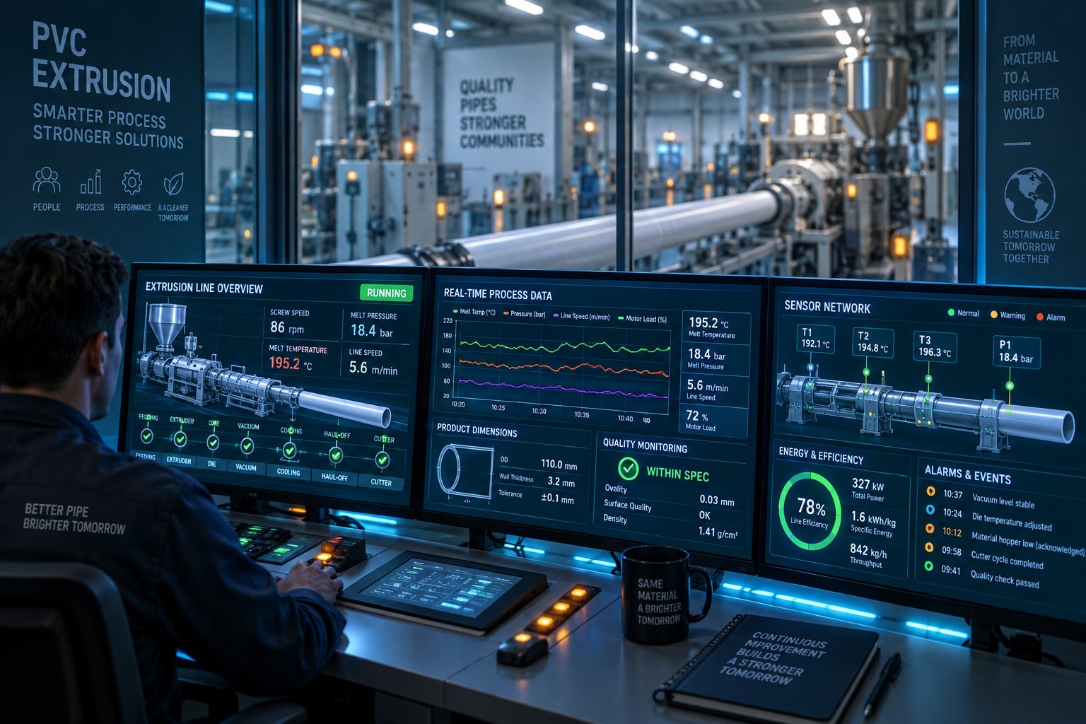
That's the promise of Industry 4.0 smart PVC extrusion monitoring — and it's moving rapidly from concept to production reality. Modern extrusion lines increasingly integrate real-time sensor networks that capture process data continuously:
- Melt pressure transducers at multiple barrel positions and the die entrance detect pressure fluctuations that signal feeding inconsistencies, screw wear progression, or die buildup — often hours before those issues produce a visible defect.
- Inline wall thickness measurement using ultrasonic or terahertz sensors provides continuous dimensional feedback, eliminating the delay between production and laboratory measurement. Deviations trigger automatic alerts or, in closed-loop systems, automatic die adjustment.
- Motor current and vibration monitoring tracks the mechanical signature of the drive system over time. As IoT-enabled extrusion platforms demonstrate, gradual increases in motor current at constant RPM reliably indicate screw wear progression — the same diagnostic signal discussed in the maintenance section, but captured automatically and trended over months without relying on manual log entries.
- Cloud-based dashboards aggregate data from all sensors into accessible interfaces that production managers, quality engineers, and maintenance teams can monitor from anywhere. Historical data retention supports trend analysis, shift-to-shift benchmarking, and predictive maintenance scheduling.
The predictive maintenance angle is particularly powerful for PVC pipe production. Vibration sensors on gearbox bearings, temperature monitoring of motor windings, and screw wear estimation algorithms that compare actual motor torque against theoretical demand can flag degradation patterns weeks before they cause quality problems or unplanned shutdowns. Industry data from smart extrusion implementations reports typical results including 15–25% reduction in unplanned downtime, 2–5% improvement in first-pass yield, and 5–10% optimization of energy consumption — with most operations achieving payback within 12–18 months.
Here's the critical insight that connects digital monitoring back to mechanical fundamentals: every smart system is only as good as the mechanical components it monitors. Automated die adjustment can't compensate for a screw that no longer plasticizes uniformly. Predictive algorithms can flag wear trends, but they can't reverse the damage. Stable plasticizing from precision-manufactured screw and barrel assemblies is the foundation that any intelligent monitoring system depends on to deliver meaningful results.
This is where component quality becomes a strategic decision rather than a procurement task. Suppliers like NANHAIYA, who provide custom conical twin screw barrels engineered specifically for PVC wear and corrosion conditions, support this foundation for pipe, profile, and board manufacturers investing in long-term production stability. When the mechanical core of your extruder delivers consistent, predictable performance run after run, smart monitoring systems can do what they're designed to do — optimize, predict, and prevent — rather than constantly compensating for hardware inconsistency.
The trajectory is clear: PVC pipe extrusion is evolving from an art dependent on operator intuition into an engineering discipline driven by data, advanced materials, and precision components working as an integrated system. The manufacturers who thrive in this environment will be those who invest in both the digital intelligence and the mechanical precision that makes it meaningful.
Frequently Asked Questions About PVC Pipe Extruders
1. What is the difference between a single-screw and twin-screw PVC pipe extruder?
A single-screw extruder relies on friction between the material and the barrel wall to convey PVC forward, making it best suited for pre-compounded flexible PVC pellets. A twin-screw extruder — particularly the conical twin-screw type — uses two intermeshing, counter-rotating screws that physically carry PVC dry-blend powder forward through positive displacement. This forced conveying, combined with self-wiping action that prevents material stagnation, makes twin-screw designs essential for rigid PVC pipe production. The conical taper further provides high torque at the feed end for powder intake and controlled shear at the discharge end for uniform plasticization, which is critical given PVC's narrow thermal processing window.
2. What temperature range is used for PVC pipe extrusion?
PVC pipe extrusion typically operates within a barrel temperature range of approximately 155°C to 200°C, distributed across four to six independently controlled heating zones. The feed zone starts lower (around 155-165°C) to avoid premature fusion that would block powder flow, while temperatures gradually increase through the compression and metering zones. The die zone generally runs at the highest setting (185-200°C) to ensure smooth surface finish. These values vary based on PVC formulation, stabilizer package, and filler content. Critically, no zone should approach 210°C, as PVC begins releasing corrosive hydrochloric acid gas above that threshold, triggering rapid thermal degradation.
3. How do I know when my PVC extruder screw and barrel need replacement?
Several progressive warning signs indicate screw and barrel wear in a PVC pipe extruder. Rising melt temperature at constant screw speed suggests widening clearance is causing material to leak backward and get re-sheared. Declining output rates — or needing higher RPM to maintain the same throughput — point to reduced conveying efficiency. Unstable melt pressure at steady-state operation signals inconsistent metering from uneven wear. Deteriorating pipe wall thickness tolerances confirm the screws can no longer homogenize melt uniformly. Logging drive current, melt pressure, and output weekly helps identify trends early. Suppliers such as NANHAIYA (nhyscrews.com) specialize in custom replacement conical twin screw barrels with PVC-specific bimetallic alloys that restore original performance and extend rebuild cycles.
4. What size PVC pipe extruder do I need for my target pipe diameter?
For conical twin-screw extruders — the standard for rigid PVC pipe — sizing follows general guidelines based on screw diameter class. A 51/105 mm to 55/110 mm machine typically handles pipe diameters from 16 mm to 110 mm, suitable for electrical conduit and small water supply lines. Mid-range 65/132 mm to 68/143 mm extruders cover 63 mm to 250 mm pipes for residential water and sewer applications. Larger 80/156 mm to 92/188 mm machines produce 160 mm to 400+ mm pipes for municipal infrastructure. These ranges depend on wall thickness, PVC formulation, and downstream line capacity. A practical best practice is to size the extruder so it runs at 70-85% of rated maximum output, leaving margin for material variation and gradual wear.
5. How can I reduce energy costs on a PVC pipe extrusion line?
Energy optimization starts with measuring specific energy consumption in kWh per kg of output — the only fair comparison metric across different machine sizes. Twin-screw extruders typically achieve 0.24-0.27 kWh/kg for rigid PVC versus 0.28-0.32 kWh/kg for single-screw machines, because intermeshing screws generate more internal shear heat and reduce external heater demand. Beyond the extruder motor and heaters, vacuum and cooling systems account for nearly 18% of total line energy draw, so optimizing downstream equipment matters equally. Maintaining screw and barrel clearance within specification prevents energy waste from material leakback and excessive re-shearing. Gravimetric feeders reduce overweight material usage, and modern servo-driven haul-off units consume less power than older hydraulic designs.
Written by
Nanhaiya Technical Team
Zhoushan Nanhaiya Plastic Machinery Co., Ltd.
The Nanhaiya technical team supports screw and barrel manufacturing projects through application review, technical communication, custom manufacturing coordination, and production and quality control.
Discuss Your Application
Related Articles
More insights on screw barrel technology and plastics processing.

What Nobody Tells You About Screw Barrel For Plastic Machine Design
Oct 10, 2026
Learn how screw barrel for plastic machine design affects melt quality, throughput, and wear life. Covers geometry, resin matching, troubleshooting, and sourcing.
Read Article
Single Screw Extruder for Sheet: Stop Guessing, Start Specifying
Oct 9, 2026
Learn how to specify a single screw extruder for sheet production. Covers screw geometry, resin-specific processing, troubleshooting, and maintenance best practices.
Read Article
PE Pipe Extruder Machine: What Datasheets Won't Tell You
Oct 9, 2026
Learn how a PE pipe extruder machine works, key specs explained, material grade selection, maintenance tips, and buyer guidance beyond the datasheet.
Read ArticleLooking for something else?
Search by material, symptom or product and jump straight to the relevant page.
These are navigation suggestions based on keyword matching — not a quotation, not a delivery commitment, and not a substitute for engineering review. Final specification is confirmed by our engineers against your drawings and processed material.
Need help with screw barrel selection?
Share your machine model, processed material and application. Our team can help with pricing and technical support.