

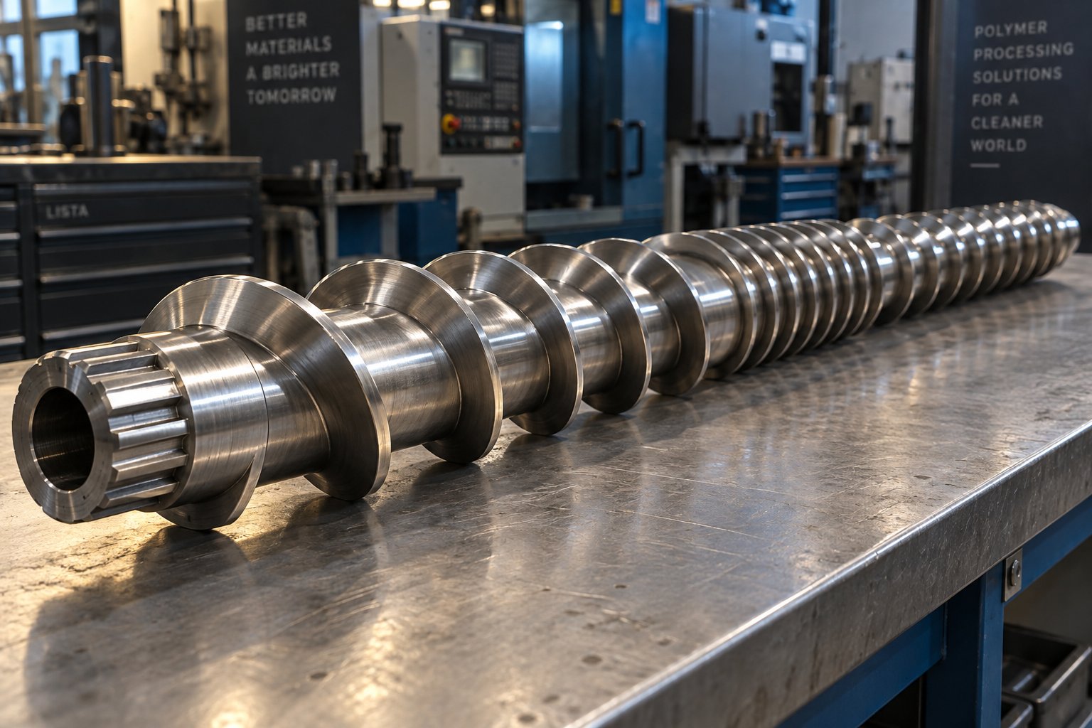
What Plastic Extruder Screw Design Controls and Why It Matters
Defining Plastic Extruder Screw Design
Plastic extruder screw design is the engineering discipline of specifying screw geometry — zone proportions, channel depths, flight characteristics, and compression profiles — to convert solid polymer pellets into a thermally and compositionally homogeneous melt at a target throughput and quality level. It encompasses everything from selecting the length-to-diameter ratio and compression ratio to choosing barrier flights, mixing elements, and surface treatments matched to a specific polymer's melt behavior. In short, it determines how efficiently raw resin becomes a usable product.
This is not a buyer's guide or a hobbyist primer. The resource you're reading takes an engineering-first perspective, mapping every geometric decision back to the physical outcome it produces — and the defect it prevents.
Why Screw Design Is the Highest-Leverage Variable
Imagine an extrusion line as a chain of systems: hopper, barrel heaters, screw, die, and downstream cooling. Among these, the screw performs the overwhelming majority of the mechanical and thermal work on the polymer. Barrel heaters contribute conductive energy, and the die shapes the final profile, but neither comes close to the screw's influence on melt quality, pressure stability, or energy consumption.
The screw is responsible for roughly 70 to 80 percent of the total work performed on the polymer, making its design the highest-leverage optimization point in any extrusion line.
A suboptimal die can often be compensated for with process adjustments. A poorly designed screw, however, creates problems — unmelts, surging, thermal degradation — that no amount of temperature tweaking or speed correction can fully resolve. Research from Paderborn University reinforces this point: maximum plasticizing and homogenizing performance is already limited by a non-optimal extruder screw, resulting in constrained throughput and economic losses regardless of how skillfully an operator sets process parameters.
How This Resource Is Structured
This article follows a progressive logic designed for practicing engineers and technical decision-makers:
- Fundamentals — Zone-by-zone anatomy of the three-zone screw and how each zone's geometry drives its function.
- Geometry parameters — L/D ratio, compression ratio, flight width, clearance, and the trade-offs each parameter introduces.
- Screw type evolution — Why barrier, mixing, and vented designs were developed and when each is justified.
- Polymer matching — A parameter-to-polymer mapping table covering polyolefins, styrenics, engineering thermoplastics, PVC, and recycled materials.
- Defect connections — How specific geometry choices cause (and correct) gels, surging, degradation, and poor dispersion.
- Scale-up and energy — Why designs that work on a lab extruder fail at production scale, and how geometry affects kWh/kg.
- Selection framework — A step-by-step methodology for choosing the right screw configuration.
Whether you're troubleshooting an existing line or specifying a screw for a new application, every section ties geometry decisions to measurable outcomes. The place to start is where every screw starts — at the feed zone and the foundational three-zone architecture.
Zone-by-Zone Anatomy of the Three-Zone Extrusion Screw
Every specialized screw — barrier, vented, mixing-enhanced — traces its lineage back to a single ancestor: the conventional three-zone metering screw. Understanding this baseline design isn't just academic. When you grasp why each zone's geometry is shaped the way it is, you'll immediately see where defects originate and where design upgrades deliver the greatest return.
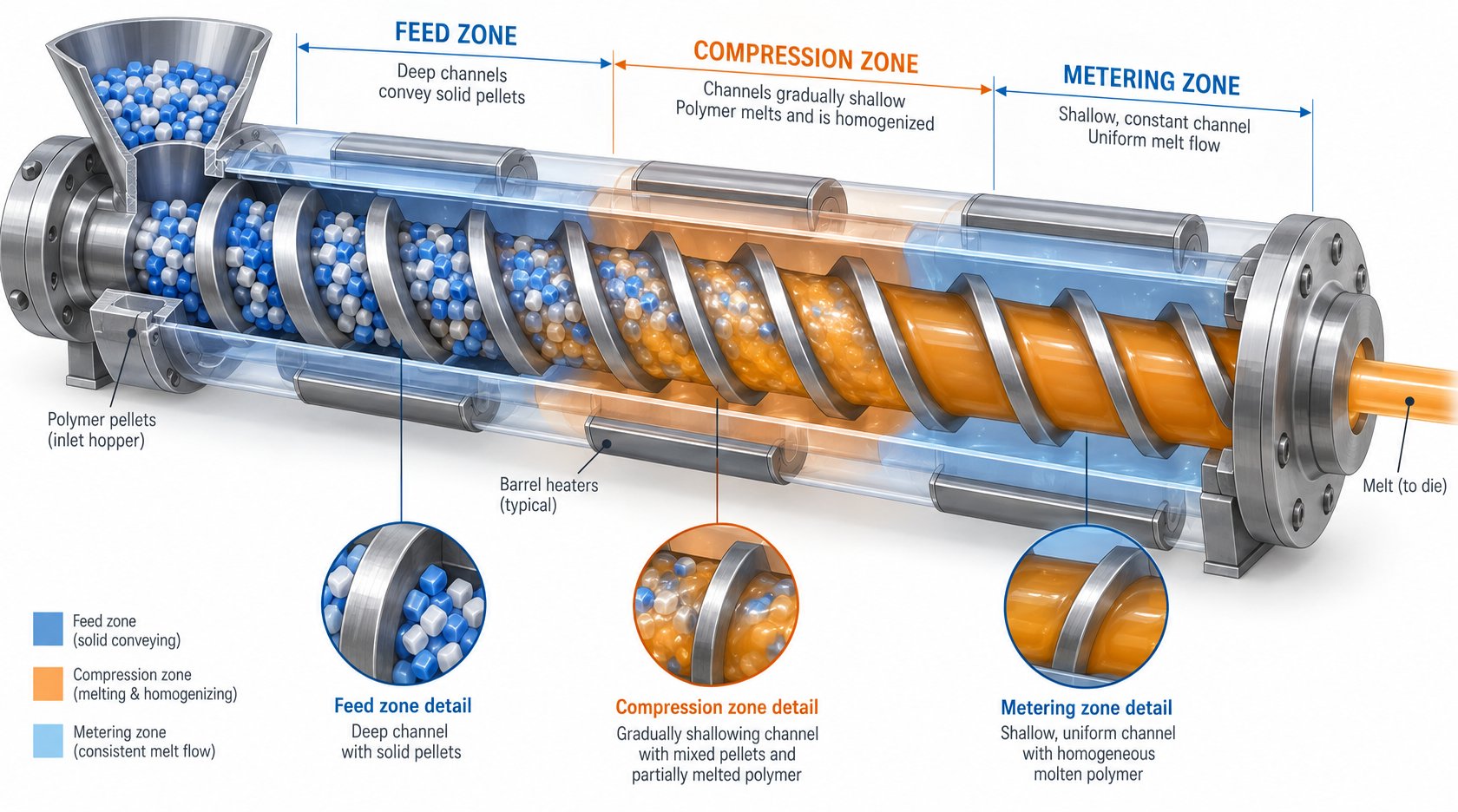
A standard three-zone extrusion screw design divides the screw's working length into a feed section, a compression (transition) section, and a metering section. Each zone has a distinct channel depth, and that depth change is what drives the entire melting and pressurization sequence. The table below summarizes how these zones relate to one another.
| Zone | Primary Function | Typical Length (Fraction of L/D) | Key Geometric Parameter | Engineering Objective |
|---|---|---|---|---|
| Feed | Accept and convey solid pellets forward | 4–8 L/D (roughly 20–35%) | Deep, constant channel depth | Maximize solids intake rate through friction-driven conveying |
| Compression (Transition) | Compact and melt the solid bed | 4–8 L/D (roughly 20–35%) | Gradually decreasing channel depth (taper) | Convert solid bed to melt pool without excessive pressure spikes |
| Metering | Homogenize melt and generate die pressure | 6–10 L/D (roughly 25–40%) | Shallow, constant channel depth | Deliver uniform melt at stable pressure to the die |
Feed Zone Design and Solids Conveying
The feed zone's job sounds simple — grab pellets and push them forward. In practice, it's one of the trickiest sections to get right because it relies entirely on friction dynamics rather than melt viscosity.
Solid pellets enter the deep channel and form what engineers call a "solid bed" — a compacted plug of granules that must slide forward along the screw channel. What makes this happen? A friction differential. The barrel wall needs to grip the solid bed more strongly than the screw root does. If friction at the barrel surface is too low, pellets rotate with the screw and go nowhere. If screw-root friction is too high, the solid bed sticks and conveying stalls. This is why the feed zone flight depth is set deep — typically the deepest channel on the entire screw — to maximize the volume of material captured per revolution and reduce compaction pressure that would increase unwanted screw-root friction.
Flight pitch in the feed zone is usually set at one screw diameter (a square pitch), which produces a helix angle of approximately 17.66 degrees. This angle represents a near-optimal balance between forward conveying force and the circumferential drag exerted by the barrel. DEM simulation research confirms that even small changes in screw pitch, channel depth, and pellet friction coefficients significantly shift the conveying angle and throughput, validating why feed zone geometry demands careful specification.
Here's where things get especially interesting. Grooved feed barrel sections — barrels with longitudinal or helical grooves machined into the bore in the feed area — fundamentally change the design calculus. In a smooth-bore barrel, solids conveying depends on the polymer-to-barrel friction coefficient, which varies with temperature and pellet geometry. Grooves replace this frictional dependence with a mechanical interlocking mechanism: pellets physically wedge into the grooves and are forced forward positively, almost independent of the friction coefficient. The result is dramatically higher and more consistent throughput, especially with slippery polymers like HDPE.
The catch? A grooved feed barrel screw design requires a shallower feed zone channel depth than a smooth-bore equivalent, because the aggressive conveying creates very high pressures at the end of the feed section. If the feed zone is too deep, more material is crammed forward than the compression zone can melt, leading to torque spikes or unmelted pellets downstream. Grooved barrel extruders are also typically designed with water-cooled feed sections to prevent premature pellet softening that would compromise the interlocking effect.
Compression Zone Geometry and Taper Options
The compression zone is where the solid bed progressively transforms into a melt pool. As channel depth decreases along this section, the solid bed is compacted against the barrel wall, squeezing out interstitial air and forcing intimate contact between pellets and the heated barrel surface. This compaction, combined with frictional and conducted heat, initiates melting.
Two fundamental taper geometry options exist for achieving this compression:
- Constant-pitch, decreasing-depth — The screw pitch remains fixed while the root diameter increases, reducing the channel depth. This is the most common approach and produces a gradual, predictable compression profile. It works well for a wide range of polymers.
- Constant-depth, decreasing-pitch — The channel depth stays the same while the flight spacing tightens, reducing the channel volume per turn. This alternative can be advantageous for materials that are sensitive to compaction pressure, since the solid bed is squeezed less aggressively in the radial direction.
The rate at which volume decreases — the compression ratio — is set by the ratio of feed zone channel depth to metering zone channel depth. A higher compression ratio means the material is squeezed more aggressively through the transition. Too much compression forces polymer against the barrel faster than heat can melt it, creating excessive pressure and potential degradation. Too little compression leaves portions of the solid bed intact, sending unmelted particles — the dreaded "unmelts" — into the metering zone and ultimately into the product.
Getting the taper rate right is also about matching the polymer's melting rate. Crystalline polymers like polyethylene absorb a large latent heat of fusion and may need a longer, gentler transition zone. Amorphous polymers like polystyrene soften progressively and tolerate a steeper compression gradient.
Metering Zone Channel Depth and Pressure Generation
By the time material reaches the metering zone, it should be fully or nearly fully molten. This zone's shallow, constant channel depth serves two simultaneous purposes: generating the pressure needed to push melt through the die and imparting enough shear to homogenize the melt thermally and compositionally.
The metering zone channel depth is the single most sensitive dimension in the entire screw. Reduce it by even a fraction of a millimeter and you noticeably increase shear rate, raise melt temperature through viscous dissipation, and boost pressure generation capacity. Increase it slightly and throughput may climb, but at the cost of reduced mixing intensity and potentially wider melt temperature variation across the channel cross-section.
Imagine squeezing toothpaste through a thin gap versus a wide one — the thin gap forces everything through at higher velocity and more uniform flow, but demands more effort. The metering channel depth works the same way. For pressure generation, a shallower channel develops higher pressure per unit length, which is essential for pushing melt through restrictive dies like complex profiles or fine-strand pelletizing plates.
This shallow-channel shear is also what provides the final thermal homogenization. Barrel heaters alone produce poor temperature uniformity because polymers are terrible thermal conductors. The thin melt layer in the metering zone, however, ensures that every element of the melt passes close to the heated barrel wall and experiences similar shear history — the primary mechanism for achieving a tight melt temperature distribution at the screw tip.
Each zone, then, has a clear engineering rationale that links geometry directly to function. But these zones don't operate in isolation — they interact through a set of shared geometric parameters, especially compression ratio and L/D ratio, whose trade-offs ripple across all three sections simultaneously.
Critical Screw Geometry Parameters and Their Engineering Trade-Offs
The three-zone architecture provides the structural framework, but it's the numerical values assigned to a handful of shared parameters that actually determine whether a screw melts, mixes, and meters effectively — or produces a stream of defects. Think of the zones as rooms in a building and the geometry parameters as the dimensions of every door, ceiling, and window. Change one measurement and you alter how everything flows through the entire structure.
This section maps each critical parameter to the outcomes it controls, building a screw geometry parameter to outcome mapping that ties directly to what you'll see at the die.
L/D Ratio and Its Effect on Residence Time
The L/D ratio — total flighted screw length divided by outer diameter — sets two things simultaneously: how long the polymer stays inside the barrel and how much functional length is available for melting, mixing, and pressure generation. A longer screw gives you more of both. A shorter one gives you less.
Standard single-screw extruders for general thermoplastics processing typically fall in the 24:1 to 30:1 range. As industry references note, 24:1 is widely used, 28:1 to 30:1 is frequently cited as most common for general-purpose lines, and values approaching 36:1 are associated with specialty or devolatilizing applications. So when is a longer L/D justified?
- Filled or compounded materials — Mineral fillers and glass fibers need additional barrel length for thorough wetting and dispersion. A 30:1 or 32:1 screw provides that extra mixing residence without forcing dangerously high screw speeds.
- High-output lines — Faster screw rotation pushes material through more quickly, reducing the effective time each polymer element spends in any given zone. A longer L/D compensates by providing more physical length for melting and homogenization.
- Polymers requiring gentle melting — Some engineering resins benefit from a gradual temperature ramp over a long compression zone, which is only feasible when total L/D is generous enough to still leave adequate feed and metering lengths.
Conversely, running a clean-melting, thermally sensitive resin like rigid PVC on a 32:1 screw can backfire. The extended residence time exposes the polymer to heat longer than necessary, increasing the risk of thermal degradation. For PVC, 20:1 to 24:1 is typical — short enough to limit heat history while still providing adequate melting length. The extruder screw L/D ratio effect on residence time is direct and non-negotiable: more length means more time in the barrel, for better or worse.
Compression Ratio — The Most Misunderstood Parameter
Compression ratio is simply the feed zone channel depth divided by the metering zone channel depth. It sounds straightforward, yet it's the parameter most frequently misspecified — and the one that causes the widest range of downstream problems when it's wrong.
Compression ratio must be matched to the bulk density ratio of the polymer being processed — the ratio of the solid pellet bulk density to the melt density. Get this relationship wrong, and no barrel temperature profile or screw speed adjustment will compensate.
Here's the logic. Polymer pellets in the feed zone occupy a certain volume that includes significant interstitial air space. As those pellets compact, melt, and become a continuous fluid, the material's density changes — it occupies less volume per unit mass. The compression ratio must account for this volumetric change. If the ratio is too high relative to the bulk density change, you're mechanically forcing material into a space that's too small, generating excessive shear heating, pressure spikes, and in the worst case, polymer degradation. If the ratio is too low, the material isn't sufficiently compacted, leaving air pockets, incomplete melting, and unmelts in the extrudate.
Consider the practical implications. Extrusion engineering expert Jim Frankland emphasizes that polymer density enters into practically every screw design calculation because output is volumetric, but energy transfer is mass-based. Semi-crystalline polymers like HDPE undergo a larger density change from solid to melt (roughly 20%) compared to amorphous polymers like PMMA (roughly 10%), because the crystalline structure packs molecules more tightly in the solid state. This is exactly why HDPE typically requires a compression ratio of 3.0:1 to 4.0:1, while PMMA works well at 2.0:1 to 2.8:1.
How compression ratio affects melt quality becomes especially visible with shear-sensitive materials. Running PVC at a 3.5:1 compression ratio — perfectly fine for polyethylene — generates enough frictional heat to degrade the polymer before it reaches the die. PVC demands ratios in the 1.6:1 to 2.2:1 range precisely because of its narrow thermal processing window and sensitivity to mechanical shear.
Flight Geometry — Width, Clearance, and Helix Angle
While L/D and compression ratio set the macro performance envelope, flight geometry fine-tunes output efficiency, wear life, and leakage behavior. These secondary parameters don't make headlines, but getting them wrong quietly erodes performance over thousands of operating hours.
Flight width (also called land width) is the radial thickness of the helical ridge at its tip. Wider flights increase the sealing surface area between the screw and barrel, reducing backward leakage flow over the flight. The trade-off? Wider flights reduce the open channel area available for material flow, which can lower throughput capacity. Standard practice sets flight width at roughly 10% of the screw diameter, but abrasive compounds may warrant wider flights to extend wear life.
Flight clearance — the radial gap between the flight tip and the barrel bore — is the parameter that degrades most visibly over a screw's service life. When new, this gap is typically tight enough to minimize the backward leakage of melt from the high-pressure metering zone toward the lower-pressure feed zone. As the flight tips wear, the clearance grows, and so does leakage flow. The consequences are measurable: reduced output efficiency, increased melt temperature from additional shear on the leaking material, and wider melt temperature variation across the channel. Tracking flight clearance over time, as industry practice recommends, is one of the simplest ways to schedule screw reconditioning before product quality deteriorates.
Helix angle determines the forward component of the drag force exerted by the barrel on the polymer. For a standard square-pitch screw (pitch equal to diameter), the helix angle is approximately 17.7 degrees. Increasing the helix angle improves solids conveying efficiency in the feed zone but reduces the number of flight turns per unit length, effectively shortening the functional processing length. Modified helix angles show up in specialty designs — powder-processing screws, for example, sometimes use a steeper pitch in the feed zone to improve intake of low-bulk-density feedstock.
The table below consolidates how these critical parameters map to recommended ranges across broad polymer families — an essential reference for extruder screw flight width and clearance design as well as core compression and L/D specifications.
| Polymer Family | Typical L/D Range | Compression Ratio | Metering Depth Range (relative) | Key Consideration |
|---|---|---|---|---|
| Polyolefins (PE, PP) | 24:1 – 30:1 | 3.0:1 – 4.0:1 | Moderate to shallow | High compression needed due to large solid-to-melt density change; semi-crystalline latent heat requires adequate melting length |
| Styrenics (PS, ABS) | 24:1 – 30:1 | 2.0:1 – 3.0:1 | Moderate | Amorphous — smaller density change, progressive softening allows moderate compression |
| Engineering Thermoplastics (PA, PC, POM) | 24:1 – 32:1 | 2.5:1 – 3.5:1 | Moderate to shallow | Higher processing temperatures; PA requires drying consideration; POM is thermally sensitive |
| PVC (rigid and flexible) | 20:1 – 24:1 | 1.6:1 – 2.2:1 | Deep (to minimize shear) | Extremely shear- and heat-sensitive; low compression and short residence time are critical |
| Recycled / Regrind Materials | 26:1 – 32:1 | 2.5:1 – 3.5:1 | Moderate | Variable bulk density and contamination; longer L/D for mixing; may require venting |
You'll notice that compression ratio for different polymer families tracks closely with the solid-to-melt density change — confirming the engineering principle highlighted above. Polyolefins, with their large crystalline density shift, sit at the high end. PVC, with its narrow thermal window and minimal density change, sits at the low end. Everything else falls between, scaled by a combination of thermal sensitivity, melt viscosity, and crystallinity.
These parameters, however, describe a static screw geometry. The reality of polymer processing is that the conventional metering screw — even with perfectly optimized L/D, compression ratio, and flight geometry — still suffers from a fundamental instability in how it melts the solid bed. That phenomenon, and the design innovations it inspired, reshaped the entire field of screw engineering.
From Metering to Barrier — How Screw Designs Evolved
The conventional three-zone metering screw, for all its elegant simplicity, carries a hidden liability. Inside the compression zone, the solid bed — that compacted plug of pellets sliding forward along the barrel wall — doesn't always melt in the orderly, progressive manner the textbook diagrams suggest. Instead, melt can work its way underneath the solid bed, undermining its structural integrity until it fractures into irregular chunks. This phenomenon, known as solid bed breakup in extrusion screws, is the single most common source of unmelted particles ("unmelts") and output instability in metering screw designs.
Why is this so damaging? When the solid bed is intact, it presents a continuous surface pressed firmly against the hot barrel wall. Melting is driven by viscous dissipation at the barrel-solid interface — an efficient, high-heat-transfer mechanism. The moment the bed breaks apart, those fragments are surrounded by molten polymer. They can no longer contact the barrel surface directly, and melting shifts to conduction through the surrounding melt. Since polymers are effective insulators, conductive melting is drastically slower. Crystalline polymers like polyethylene are especially vulnerable because they do not appreciably soften before reaching their melt point, requiring substantial additional energy to overcome the heat of fusion through this inefficient conduction path.
The broken fragments are simply conveyed forward, sometimes reaching the metering zone and even the die — showing up as visible specks, surface imperfections, or weak spots in the final product. Equally problematic, the irregular melting creates pressure fluctuations that manifest as output surging, making dimensional control of the extrudate nearly impossible.
This core limitation motivated every major advance in screw engineering that followed.
Barrier Screw Principles — Maillefer, Barr, and Beyond
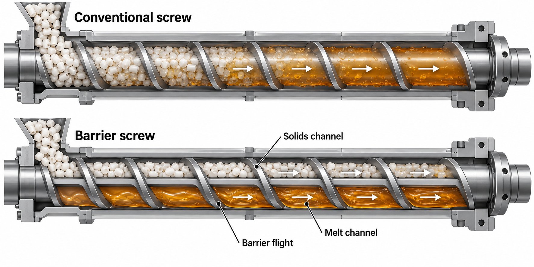
The breakthrough idea behind barrier screw design was deceptively straightforward: if solid bed breakup is the problem, physically prevent it by separating the solid bed from the melt pool. A secondary flight — the barrier flight — is introduced alongside the primary flight, dividing the screw channel into two distinct sub-channels: a solids channel and a melt channel.
Imagine "unwrapping" the screw into a flat channel, as extrusion engineers often visualize it. In the Maillefer barrier screw working principle, the solids channel gradually narrows in width while the melt channel widens. As the solid bed melts at the barrel interface, the resulting thin melt film is forced over the barrier flight — which is set slightly lower than the primary flight — and into the melt channel. The solids, too large to pass over the barrier gap, remain trapped in the solids channel, maintaining bed integrity throughout the melting process. By the time material reaches the end of the barrier section, only fully melted polymer occupies the melt channel.
The Barr barrier screw works on the same separation principle but uses a different channel geometry, with the barrier flight typically starting further downstream and employing variations in how the solids and melt channels change proportion. Both designs share the critical advantage: because the solid bed stays intact and compressed against the barrel wall, viscous-dissipation melting remains the dominant heat transfer mechanism over the full length of the barrier section, dramatically improving melting efficiency compared to a conventional design.
As extrusion consultant Jim Frankland explains, barrier screws essentially ensure that a more thermally homogeneous melt exits the screw without the need for a restrictive downstream mixing section — solids are completely melted by the time they reach the metering zone. Many conventional screws, by contrast, rely on mixing sections at the end of the screw to finish melting what the compression zone could not.
Barrier designs aren't without their own engineering challenges, though. If the compression section within the barrier zone is too gradual, melt can still accumulate beneath the solid bed inside the solids channel, causing localized breakup. When fragments collect in the narrowing solids channel, they form a plug that generates enormous localized pressures. Frankland documented a case on an 8-inch barrier screw where this plugging generated an estimated 350,000 pounds of force over a 45-inch span — enough to bend the screw shaft 0.100 inch and cause catastrophic flight wear on one side of the barrel. The takeaway? Barrier screw design vs metering screw comparison isn't a simple "barrier is always better" equation. The barrier section's taper rate, barrier clearance, and channel width progression must be carefully engineered to match the melting rate of the specific polymer.
Dispersive vs. Distributive Mixing Elements
Barrier flights solved the melting problem, but they didn't solve every quality problem. Even a fully melted, surgeless melt stream can contain poorly dispersed pigment agglomerates, localized temperature variations, or incompletely incorporated additives. These are mixing problems — and they require dedicated mixing elements that the basic helical channel geometry of any screw, barrier or metering, simply cannot deliver.
Understanding dispersive vs distributive mixing in single screw extruders is essential for specifying the right element:
- Dispersive mixing applies high stress to the melt to break down agglomerates, gels, and undispersed additive clusters into smaller particles. The mechanism is mechanical — forcing melt through narrow gaps where shear stress exceeds the cohesive strength holding the agglomerate together.
- Distributive mixing rearranges and reorients melt streams to spread all components uniformly throughout the volume. It doesn't need high stress — it needs repeated splitting, reorientation, and recombination of flow paths. Think of folding dough rather than grinding it.
Most real-world applications require some degree of both, but the dominant need determines which mixer type to specify.
The Maddock mixer (also known as the Union Carbide mixer) is arguably the most widely used dispersive mixing element in North American single-screw extrusion. Originally developed by Gene LeRoy and popularized by Bruce Maddock in the early 1970s for film and cable-jacket processing, this Maddock mixer dispersive mixing element features a series of axial or helical flutes separated by barrier lands. Melt enters the inlet flutes, is forced over the barrier lands — where it experiences high shear — and exits through adjacent outlet flutes. The barrier land width and gap height control the degree of dispersive mixing: narrower gaps mean higher shear stress, more effective gel reduction, and better pigment dispersion, but also greater pressure drop and more viscous heating.
A common variation — the spiral Maddock — angles the flutes helically to add a pumping effect and potential self-cleaning behavior. As Frankland cautions, however, simply converting axial flutes to a helical layout without recalculating groove volume, barrier width, and flow path length can actually degrade performance. In one analyzed configuration, a 5-inch helical lead increased groove length by 75% while reducing groove volume by 40%, producing several times the pressure drop of the original axial design. Not all spiral Maddock mixers are created equal — the design requires deliberate engineering, not just geometric fitting.
Pineapple mixers (pin mixers) take a fundamentally different approach. A series of pins protruding from the screw root interrupt the laminar flow, repeatedly splitting and recombining the melt streams. The shear generated is moderate, making pineapple mixers ideal for distributive mixing of shear-sensitive polymers or applications where homogeneity rather than particle size reduction is the primary goal. They work well for blending color concentrates, distributing liquid additives, and evening out thermal gradients — situations where gentle reorientation outperforms brute-force shearing.
Cavity transfer mixers (CTMs) push distributive mixing further by using hemispherical cavities machined into both the screw surface and the barrel bore. As the screw rotates, material is transferred between stator (barrel) and rotor (screw) cavities, producing exponential flow-splitting — each cavity exchange effectively doubles the number of melt layers. This makes CTMs exceptionally effective for achieving color homogeneity and for dispersing low-percentage additives at the micrometer scale, all without the high shear stress that would degrade sensitive polymers or break reinforcing fibers.
The table below provides a quick-reference comparison for selecting the right mixing element based on the dominant mixing objective.
| Mixer Type | Primary Mixing Mode | Mechanism | Best Suited For | Key Trade-Off |
|---|---|---|---|---|
| Maddock (axial or spiral) | Dispersive | High shear over barrier lands | Gel reduction, pigment dispersion, masterbatch processing | Higher pressure drop; risk of excessive shear heating if poorly sized |
| Pineapple (pin mixer) | Distributive | Flow splitting and recombination around pins | Color blending, liquid additives, shear-sensitive polymers | Limited dispersive capability; less effective on hard agglomerates |
| Cavity transfer mixer (CTM) | Distributive (high intensity) | Exponential layer multiplication via stator-rotor cavity exchanges | Precision color uniformity, fiber-filled compounds, low-concentration additives | Complex machining; higher cost; limited availability for all screw sizes |
In practice, modern screw designs frequently combine elements — a barrier melting section followed by a Maddock dispersive mixer, for instance, or a barrier section paired with a pineapple section for shear-sensitive color work. The selection hinges on whether the dominant quality problem is melting (barrier), particle size reduction (dispersive mixer), or uniformity (distributive mixer).
Melting, mixing, and homogenization cover most extrusion requirements — but they don't address what happens when the polymer itself carries moisture or volatile contaminants that must be removed mid-process. That challenge demanded yet another architectural innovation: the vented, two-stage screw.
Vented Screw Configurations and Process Control Interactions
Hygroscopic polymers like nylon and polycarbonate absorb atmospheric moisture that, if left in the melt, produces splay marks, bubbles, and degraded mechanical properties. Recycled materials carry trapped air, residual solvents, and volatile contaminants. Pre-drying is one solution — but it adds cost, floor space, and process complexity. The vented two-stage extruder screw design offers an alternative: remove volatiles inside the extruder itself, mid-process, by exploiting a carefully engineered pressure drop along the screw.
Vented Two-Stage Screw Architecture
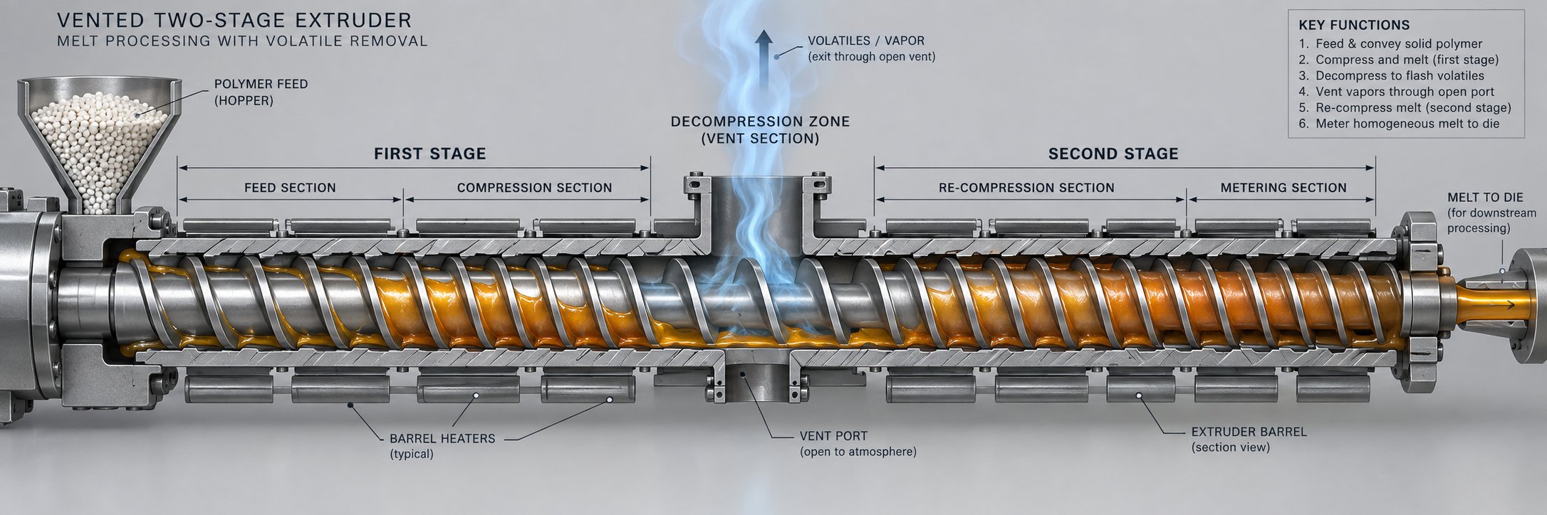
Imagine two complete screws stacked end to end on a single shaft. That's essentially what a vented screw is — a two-stage design where the first stage melts and compresses the polymer just like a conventional three-zone screw, then hands the melt off to a decompression zone where the channel depth increases sharply. This sudden deepening drops the melt pressure to atmospheric (or below, under vacuum), and with the pressure barrier removed, dissolved moisture, unreacted monomers, and trapped gases flash out of the melt surface and escape through a vent port machined into the barrel.
The second stage picks up the degassed melt, re-compresses it, and meters it forward at stable pressure to the die. In effect, the second stage functions as a melt-fed screw — it doesn't need to handle solids conveying or initial melting, only re-pressurization and final homogenization.
A useful rule of thumb from devolatilization practice: each vent can reduce volatile concentration by roughly an order of magnitude. A single-vent, two-stage screw might bring moisture from 0.2% down to 0.02%. For applications demanding even lower residuals — certain medical-grade or food-contact polymers — three-stage screws with two vent ports are employed, driving volatiles below hundredths of a percent.
The critical design constraint is straightforward in principle but demanding in execution: the second stage must have a higher pumping capacity than the first. If the first stage pushes more melt forward than the second stage can swallow, molten polymer backs up under the vent opening and floods out the port. This vent flooding scenario is one of the most disruptive failures in extrusion — it halts production and requires labor-intensive cleanup. To prevent it, screw designers deliberately make the first stage "pressure-starved" relative to the second by specifying a deeper metering depth in the second stage or by using a mixing element between stages that acts as a flow restriction and upstream seal.
The decompression zone itself must be sized to the devolatilization requirement. Deeper channels expose more melt surface area for volatile escape, but excessively deep channels create stagnant pockets where material can hang up and degrade. As SpiraMelt's engineering team notes, traditional deep-channel vent sections leave the resin as a "blob with low surface area exposed for degassing." More advanced designs incorporate multiple flights or helical vent-section geometry to separate the melt into thinner strands, dramatically increasing the surface-to-volume ratio and improving volatile extraction efficiency.
L/D requirements climb significantly with vented designs. A conventional single-stage screw might work well at 24:1. A vented two-stage screw for the same polymer typically demands 30:1 to 36:1, because the decompression zone, vent section, and second-stage compression all consume axial length that would otherwise be available for melting and pumping. This is one reason vented extrusion inherently sacrifices some throughput relative to a non-vented screw of the same diameter — you're dedicating barrel real estate to devolatilization instead of output.
Screw Design Interaction with Process Controls
No screw operates in a vacuum — well, some vent ports literally do — but the broader point is that geometry and process settings are deeply intertwined. A perfectly specified devolatilization screw for hygroscopic polymers will still underperform if barrel temperatures, screw speed, and back pressure aren't aligned with the design intent.
Barrel temperature profiles interact with screw geometry through two mechanisms. First, higher barrel temperatures in the first stage accelerate melting, ensuring the polymer is fully liquid before reaching the vent. If unmelted pellets reach the decompression zone, volatiles trapped inside them won't be extracted — the solid matrix simply won't release dissolved gases effectively. Second, in the vent zone itself, elevated melt temperature increases the vapor pressure of dissolved volatiles, driving more aggressive devolatilization. The trade-off is thermal degradation: push temperatures too high to maximize volatile removal, and you risk damaging the polymer chain.
Screw speed changes the balance between stages in a way that directly affects vent stability. Increasing RPM boosts throughput, but it also shortens the filled length behind both the upstream and downstream seals that isolate the vent zone. As devolatilization specialist Rob Jerman explains, higher screw speed makes seals more susceptible to failing, while lower speed lengthens the filled region behind each seal — reducing the risk of air ingress at the upstream seal but potentially causing polymer backup and vent flooding at the downstream seal. In twin-screw extruders, this effect is even more pronounced, but single-screw vented designs face the same fundamental sensitivity.
Back pressure from the die creates the downstream resistance the second stage must overcome. Higher die pressure demands more pumping from the second-stage metering section, which in turn pulls more melt forward from the vent zone. If die pressure climbs unexpectedly — from a screen pack clogging, for instance — the second stage can become starved, causing the first stage's output to overwhelm the vent zone. This is why how to prevent vent flooding in extrusion isn't just a screw design question; it's a system design question that involves die restriction, screen changers, and downstream equipment as well.
Melt Quality Metrics Linked to Screw Design
Every geometry decision discussed so far — zone depths, compression ratio, barrier flights, mixer selection, vent architecture — ultimately manifests in a set of measurable melt quality outcomes. Research from Paderborn University formalized this relationship through a screw performance index (SPI), demonstrating that screw geometry correlates directly with both the thermal and material homogeneity of the melt. The practical takeaway? If you can measure it at the screw tip, screw design almost certainly influences it.
The key melt quality metrics that screw geometry directly controls include:
- Melt temperature uniformity — The standard deviation of melt temperature across the channel cross-section. Shallow metering zones and effective mixing elements reduce this deviation; deep channels and absent mixers widen it. Poor thermal homogeneity leads to different flow velocities at the die exit, causing dimensional inconsistency in the extrudate.
- Pressure stability (surge) — Cyclic pressure fluctuations at the screw tip, typically caused by solid bed breakup or inconsistent solids conveying. Barrier screws dramatically reduce pressure oscillation. A well-designed metering zone depth also contributes by maintaining a consistent drag-flow-to-pressure-flow ratio.
- Specific energy consumption (kWh/kg) — The total energy input per kilogram of processed polymer. This metric captures how efficiently the screw converts electrical motor energy into useful melting and conveying work versus waste heat. Screws with excessive shear in the metering zone or poor melting efficiency in the compression zone drive this number up without improving output.
- Melt homogeneity (material uniformity) — Assessed through techniques like the dead-stop test and gray-value analysis of thin-section samples, this metric reflects how evenly additives, pigments, and fillers are distributed. Mixing elements are the primary geometric lever, with Maddock-type dispersive mixers reducing agglomerate size and distributive elements like pineapple or cavity transfer mixers improving spatial uniformity.
- Degree of melting — The fraction of polymer that is fully molten at the screw tip. Solid particles at the die exit indicate insufficient melting length, inadequate compression ratio, or the absence of barrier flights. As throughput increases, the melting point shifts toward the screw tip, reducing the available length for homogenization and increasing the likelihood of unmelts.
These metrics aren't independent — they interact. Raising screw speed to boost throughput typically increases melt temperature non-uniformity and pressure variation while reducing the degree of melting, as the Paderborn University experiments confirmed across barrier screws, three-section screws, and shear-mixing combinations. The screw design effect on melt temperature uniformity is especially sensitive to throughput increases because higher output compresses the available residence time for thermal equilibration.
With a clear picture of how vented architectures, process controls, and melt quality metrics connect back to geometry, the next practical challenge is matching all of these variables to the specific polymer being processed — a task that requires a systematic parameter-to-polymer mapping.
Matching Screw Geometry and Materials to Polymer Families
Selecting the right compression ratio, L/D, and metering depth in isolation is useful — but polymers don't process in isolation either. A screw that runs HDPE beautifully may destroy PVC in minutes. The differences stem from each polymer family's crystallinity, shear sensitivity, thermal stability, and abrasiveness, all of which must map simultaneously to screw type, geometry, and metallurgy. The table below consolidates these relationships into the kind of polymer-to-screw reference that practicing engineers actually need on the shop floor.
Polymer-to-Screw Parameter Mapping Table
Each recommendation in this table reflects the engineering rationale discussed in earlier sections — screw compression ratio by polymer type tracks the bulk-density-to-melt-density change, L/D accommodates melting length and residence time constraints, and screw type addresses whether solid bed breakup, devolatilization, or mixing is the dominant challenge.
| Polymer Family | Recommended Screw Type | Typical L/D Range | Compression Ratio | Metering Depth Range | Special Considerations |
|---|---|---|---|---|---|
| Polyolefins (PE, PP) | Barrier + Maddock mixer | 24:1 – 30:1 | 3.0:1 – 4.0:1 | 2.5 – 4.0 mm (size dependent) | High crystalline density change demands aggressive compression; barrier flight critical for HDPE to prevent solid bed breakup; extruder screw design parameters for polyolefins favor deeper feed zones for high bulk-density pellets |
| Styrenics (PS, ABS) | Metering or barrier + distributive mixer | 24:1 – 30:1 | 2.0:1 – 3.0:1 | 2.5 – 3.5 mm | Amorphous — progressive softening allows moderate compression; ABS benefits from barrier flights for rubber-phase dispersion; pin mixer improves color uniformity |
| Engineering Thermoplastics (PA, PC, POM) | Barrier + Maddock or vented two-stage | 24:1 – 34:1 | 2.5:1 – 3.5:1 | 2.0 – 3.5 mm | PA is hygroscopic — vented screw eliminates pre-drying; POM releases formaldehyde at high shear — requires gentle compression; PC demands tight melt temperature control |
| PVC (rigid and flexible) | Metering (no barrier) | 20:1 – 24:1 | 1.6:1 – 2.2:1 | 3.5 – 5.0 mm (deep) | PVC low shear screw design requirements dominate: minimal frictional heat, short residence time, deep metering channel to avoid degradation; barrier flights add dangerous shear; corrosion-resistant metallurgy essential due to HCl release |
| Recycled / Regrind Materials | Vented two-stage + dispersive mixer | 28:1 – 36:1 | 2.5:1 – 3.5:1 | 2.5 – 4.0 mm | Variable bulk density and contamination; longer L/D for devolatilization and mixing; dispersive mixer needed for gel reduction; abrasive fillers may require hard-faced flights |
You'll notice that PVC sits in a category of its own. Its narrow thermal processing window — roughly 170 to 210 degrees Celsius before degradation accelerates — rules out barrier flights, high compression, and tight metering channels that work perfectly well for polyolefins. Meanwhile, recycled feedstocks demand almost every feature available: venting for volatiles, mixing for homogeneity, and extended L/D for residence time. No single "general-purpose" screw covers both ends of this spectrum.
Screw Material Selection and Surface Treatment
Geometry is only half the specification. The screw's metallurgy and surface treatment determine how long that geometry survives in service — and whether the polymer itself is contaminated by wear debris.
Standard screws for non-abrasive polyolefins are typically manufactured from 4140 or 4340 alloy steel, case-hardened by nitriding. A nitrided screw surface treatment for extrusion produces a hard, wear-resistant case (typically 55–70 HRC) that resists the mild abrasion of unfilled pellets at a reasonable cost. For most commodity resin processing, nitriding provides an excellent cost-to-wear-life ratio.
Abrasive compounds — glass-fiber-reinforced nylon, mineral-filled polypropylene, wood-plastic composites — demand something tougher. A bimetallic screw barrel for abrasive polymers pairs a tungsten-carbide barrel liner with flight hardfacings of cobalt- or nickel-based alloys like Stellite or Colmonoy 56. These weldments protect the flight tips — the highest-wear zone — while the base shaft retains the toughness needed to absorb torsional loads. For severely abrasive applications, overall chromium carbide coatings on the screw body offer full-surface protection, though at significantly higher cost.
Corrosive polymers introduce a different threat. PVC releases hydrochloric acid during processing; fluoropolymers generate hydrofluoric acid. Standard nitrided or tool-steel surfaces pit and erode rapidly under these conditions. Nickel-based alloys — Hastelloy, Inconel, and Monel — resist acid attack and are the materials of choice for fluoropolymer screws. For PVC, chrome plating or nickel-based coatings provide adequate corrosion protection at moderate cost, though even small coating defects can accelerate localized pitting.
A subtlety that catches many processors: corrosion-resistant alloys have a lower coefficient of thermal expansion than standard steel. Running a corrosion-resistant screw in a standard barrel — or vice versa — changes the flight-to-barrel clearance as temperatures climb, potentially causing binding and catastrophic wear. Screw and barrel metallurgy must be matched as a system, not selected independently.
When Custom Screw Engineering Makes the Difference
The table and material recommendations above give you a solid starting framework. In practice, though, real applications rarely fall neatly into a single row. Imagine processing a 30% glass-filled nylon 6/6 on a vented extruder destined for automotive under-hood components. You need barrier flights for melting efficiency, a vented second stage for moisture removal, a dispersive mixer for fiber distribution, a bimetallic barrel for abrasion resistance, and a corrosion-resistant screw coating because nylon's processing byproducts are mildly acidic. Every geometric and metallurgical variable interacts with every other.
Matching all these variables simultaneously — geometry, materials, coatings, and polymer-specific requirements — is where custom screw design services from specialists add measurable value. NANHAIYA's custom screw design engineering addresses exactly this complexity, helping processors match screw geometry, barrel design, material selection, and surface treatment to their specific polymers, output targets, and quality requirements. For straightforward commodity processing, the parameter guidelines in this article may be sufficient. For multi-variable applications with tight tolerances or novel materials, application-specific engineering support turns good specifications into optimized ones.
Geometry and metallurgy define what a screw can do. The real proof, however, shows up at the die — where design shortcomings surface as tangible, costly defects. Connecting specific geometry decisions to the defects they cause (and correct) is what transforms screw specification from a catalog exercise into a diagnostic tool.
How Screw Design Drives Extrusion Defects and Corrections
Most troubleshooting guides treat extrusion defects as process control problems — adjust the temperature here, slow the screw speed there. That approach works when the root cause is operational. But when defects persist despite careful process optimization, the problem almost always traces back to the screw itself. Extrusion defects caused by screw design don't respond to thermocouple tweaks or operator intuition. They respond to geometry changes.
Every persistent extrusion defect should prompt a screw design review before adjusting process parameters. If the geometry is wrong for the polymer, no barrel temperature profile or screw speed setting will produce a lasting fix.
The defect categories below are ranked by frequency and production impact. For each one, you'll find the specific screw zone and parameter that serves as the primary design lever for correction — tying directly back to the geometry principles, zone functions, and screw types covered in earlier sections.
- Gels, unmelts, and incomplete melting
- Surging and output instability
- Thermal degradation
- Poor color and additive dispersion
- Moisture-related defects (splay, bubbles, pinholes)
Gels, Unmelt, and Incomplete Melting
Unmelted polymer fragments and gels are arguably the most common screw-related defects in single-screw extrusion, especially in film and thin-wall applications. They fall into three distinct subcategories, each pointing to a different geometric root cause.
Solid polymer fragments appear when the solids conveying rate and metering rate outpace the screw's melting capacity. Here's the critical insight: when you double the screw speed, solids conveying and metering rates roughly double, but melting rate increases by only a factor of about 1.4. At some speed threshold, the screw simply cannot melt everything before it reaches the discharge. The primary design levers are:
- Compression ratio — Too low a ratio relative to the polymer's bulk-density-to-melt-density change leaves insufficient compaction energy for melting. If you're seeing gels and unmelt from wrong compression ratio, the metering zone channel depth is too deep or the feed zone channel depth is too shallow for the resin.
- Melting length (L/D) — A short overall L/D or a truncated compression zone limits the barrel contact length available for viscous-dissipation melting. High-output lines processing crystalline polymers like HDPE are especially vulnerable.
- Barrier flights — Conventional metering screws allow the solid bed to break up, scattering fragments into the melt pool where conduction-only melting is painfully slow. Adding a barrier section keeps the solid bed intact against the barrel wall, maintaining the efficient drag-induced melting mechanism discussed in earlier sections.
- Maddock mixer at discharge — Even when some solid fragments slip through, a Maddock-type mixer near the screw tip is well suited for trapping, melting, and dispersing these remnants before they reach the die.
Highly entangled gels are a subtler problem. These aren't truly unmelted — they're molten high-molecular-weight species that are so tightly entangled they behave like solid particles. They solidify first upon cooling, producing visible defects in film that look identical to solid fragments but have a completely different origin. Hot-stage microscopy reveals the difference: when stressed at melt temperature, the entangled chains disentangle and do not reappear upon cooling. The design fix is a Maddock mixer with a tighter-than-standard clearance on the mixing flight — typically an undercut of about 0.5% of the barrel diameter rather than the more common 1 to 1.5%. This tighter gap generates shear stresses of 100 to 200 kPa, which is enough to pull apart the entangled chains.
Degradation gels — crosslinked or oxidized polymer particles — form in stagnant regions of the screw where material sits at elevated temperature for extended periods. Poorly designed barrier section entries, excessively deep Maddock mixer flutes, and small flight radii in the metering channel are the three most common design-related stagnation sources. When flight radii are smaller than the local channel depth, they create recirculation pockets known as Moffatt eddies where resin degrades over hours or days and then periodically breaks free, producing a "gel shower" in the product. The corrective specification? Request flight radii in the metering channel at 1.5 times the channel depth when ordering new screws.
Surging and Output Instability
Surging — the rhythmic pulsation of extruder output — shows up as periodic thickness variations in sheet, diameter fluctuations in tubing, and weight inconsistency in pelletizing. When you see it on a pressure gauge at the screw tip, the waveform is unmistakable: a sawtooth or sinusoidal oscillation that no amount of PID tuning on the screw drive can eliminate.
The dominant screw-design cause is solid bed breakup in the compression zone. As described earlier, the solid bed in a conventional metering screw can fracture when melt penetrates beneath it, sending irregular chunks of partially melted polymer forward. These chunks momentarily block the metering channel, causing pressure to spike, then release as they melt through, causing pressure to drop. The cycle repeats with each new fracture event.
The extruder output surging screw design fix targets two parameters:
- Barrier flights — The most effective single change. By physically separating the solid bed from the melt pool, barrier screws prevent the bed fracture that initiates the surge cycle. Processors who switch from a conventional metering screw to a well-designed barrier screw frequently report pressure stability improvements from plus or minus 200 psi down to plus or minus 30 psi — an order-of-magnitude reduction.
- Metering zone depth — An improperly deep metering channel reduces the ratio of drag flow to pressure flow, making the screw's output more sensitive to downstream pressure changes (from screen pack loading, die resistance fluctuations, or melt temperature shifts). Shallowing the metering channel stiffens the screw's pumping characteristic, reducing the output variation per unit of pressure change. The trade-off is increased shear heating, so the depth must be optimized rather than simply minimized.
A secondary contributor to surging is inconsistent solids conveying in the feed zone, particularly with slippery resins or irregular regrind particles. Grooved feed barrel sections, discussed in the three-zone anatomy section, address this by replacing friction-dependent conveying with positive mechanical transport.
Degradation, Poor Dispersion, and Moisture Defects
Thermal degradation manifests as discolored streaks, black specks, reduced mechanical properties, or off-gassing at the die. When it's screw-related, two geometry issues dominate. First, thermal degradation from excessive screw shear in the metering zone — a metering channel that's too shallow for the polymer's viscosity generates more viscous dissipation heat than the barrel cooling can remove, pushing the melt beyond its thermal stability window. This is especially critical for PVC, POM, and PVDC, which have narrow safe processing ranges. Second, an overly aggressive compression ratio forces rapid compaction, generating frictional heat spikes in the transition zone before the polymer has fully softened. For heat-sensitive materials, both the compression ratio and the taper gradient (how quickly the channel depth changes per turn) must be moderated.
Stagnation-induced degradation is a separate mechanism but equally tied to geometry. The barrier section entry, Maddock mixer flute design, and metering channel flight radii discussed under gels all apply here. Any screw feature that creates a dead zone — a pocket where material can accumulate and sit at processing temperature — will eventually produce degraded resin. Partially filled channels downstream of a flow restriction are a common culprit: the main melt stream passes on the pushing side while the trailing side traps a thin layer that oxidizes and crosslinks over time, then periodically releases into the product stream.
Poor color and additive dispersion is the most straightforward geometry-to-defect connection in this list. A standard helical metering channel provides laminar drag flow with almost no cross-channel mixing. Pigment concentrates, liquid additives, and processing aids that enter with the pellets get stretched into long striations rather than uniformly blended. Poor color dispersion mixing element selection — or the complete absence of mixing elements — is nearly always the cause.
The corrective approach depends on the mixing objective. If the problem is undispersed pigment agglomerates (visible as color specks), dispersive mixing via a Maddock element with an appropriately sized barrier gap applies high shear to break agglomerates apart. If the problem is color streaking or uneven tint intensity (the pigment particles are fine but unevenly distributed), distributive mixing via a pineapple mixer or cavity transfer mixer reorients and redistributes the melt without excessive shear. Many film and sheet applications benefit from both — a Maddock section for gel and agglomerate reduction followed by a distributive element for thermal and compositional homogeneity.
Moisture-related defects — splay marks, surface bubbles, internal voids, and pinholes — occur when water vapor or other volatiles expand inside or at the surface of the melt as it exits the die. As discussed in the vented screw section, hygroscopic polymers like nylon and polycarbonate absorb atmospheric moisture that vaporizes under melt processing conditions. Recycled feedstocks carry trapped air and residual contaminants that behave similarly. The screw-design response is a vented two-stage architecture that provides a decompression zone where volatiles can escape through a barrel vent port. Without this architectural provision, the only alternative is pre-drying — which adds cost, energy consumption, and another potential failure point in the process chain.
Each of these five defect categories traces to specific, identifiable screw geometry decisions. The practical implication is significant: when a persistent quality problem resists process-parameter adjustments, the diagnostic should shift from "what settings are wrong" to "what geometry is wrong." The screw zone, the parameter, and the design correction are predictable once you understand the mechanism.
Correcting defects on an existing line, however, is only half the challenge. When the goal is scaling a proven process from pilot to production — or reducing energy consumption on a running line — the geometry rules shift in ways that catch even experienced engineers off guard.
Scale-Up Principles and Energy-Efficient Screw Design
A screw that delivers flawless HDPE blown film on a 40 mm lab extruder at 30 kg/h doesn't automatically perform the same way when you enlarge it proportionally and bolt it into a 120 mm production machine targeting 500 kg/h. Every engineer who has attempted a straightforward lab extruder to production screw scale-up has discovered this the hard way: what scales is the geometry; what doesn't scale is the physics. Shear rates, heat transfer distances, residence times, and leakage flows all shift in non-proportional ways as diameter increases, and ignoring these shifts produces hotter melt, poorer homogeneity, and wasted energy at production scale.
This section explains why screw geometry does not scale linearly — and how that same understanding opens the door to energy-efficient extrusion screw geometry that lowers operating cost per kilogram.
Why Screw Designs Do Not Scale Linearly
The root of the problem is surprisingly simple. As screw diameter increases, channel volume grows with the square of the diameter ratio. Extrusion engineer Jim Frankland demonstrated this directly: one turn of a 4-inch screw holds exactly four times the volume of one turn of a geometrically identical 2-inch screw, because both channel width and circumferential length increase with diameter. At the same screw RPM and channel depth, output therefore scales as (D1/D2)2.
Sounds favorable — but consider what happens to shear rate. The shear rate in the metering channel is described by:
Shear rate = pi x D x N / h
where D is screw diameter, N is rotational speed, and h is channel depth. If you keep the same channel depth and the same RPM, shear rate increases linearly with diameter — a 120 mm screw generates three times the channel shear of a 40 mm screw at equal RPM and equal metering depth. That elevated shear translates directly into higher viscous dissipation, hotter melt temperatures, and potential thermal degradation of the polymer.
The conventional response was to deepen the metering channel on larger screws. Early practice scaled channel depth by the square root of the diameter ratio: (D1/D2)0.5. Bruce Maddock, working at Union Carbide's development lab in the 1970s with extruders up to 4.5 inches, refined this to the 0.7 power: (D1/D2)0.7. This exponent better accounts for the combined effects of increased heat-transfer distances, higher shear heating over the flights from greater peripheral speed, larger flight clearances that increase leakage flow, and the reduced ratio of barrel cooling area to output volume. The 0.7 power produces a deeper channel than the square-root method, compensating for these compounding effects.
Why does this matter practically? Imagine scaling a metering depth from a 2.5-inch screw to a 4.5-inch production screw:
- Square-root method (0.5 power) — Metering depth increases by a factor of (4.5/2.5)0.5 = 1.34x
- Maddock method (0.7 power) — Metering depth increases by a factor of (4.5/2.5)0.7 = 1.51x
That 12% difference in channel depth meaningfully changes shear rate, melt temperature, and mixing intensity at production scale. C.I. Chung, in his Extrusion of Polymers textbook, independently arrived at the same 0.7 power as a "balanced" basis for scale-up — corroborating the practical data Union Carbide had gathered making blown film across multiple extruder sizes.
Beyond channel depth, other extruder screw design scale-up principles introduce additional complexity:
- Specific output (kg/h per rpm) increases with the square of the diameter at equal channel depth, so a production screw requires far fewer RPM per kilogram than a lab screw. This changes the melting dynamics because lower RPM means lower shear, longer residence times per revolution, and more reliance on conductive barrel heating — which, as process scale-up research confirms, becomes less effective at larger diameters because the barrel surface area-to-volume ratio shrinks.
- Compression ratio may need adjustment because the deeper feed and metering channels on the larger screw change the effective compaction and shear balance in the transition zone. A compression ratio that produced smooth melting on a 40 mm screw can be either too aggressive or too gentle on a 120 mm machine.
- Melting rate does not scale with the square of the diameter — it scales more slowly, closer to the first power, because melting depends on barrel-to-melt contact area (a surface phenomenon) rather than channel volume. At high screw speeds on large machines, solids conveying can outpace melting capacity, producing the same unmelt and surging problems discussed in the defect section.
The bottom line: proportional geometric enlargement preserves the screw's shape but distorts its thermomechanical behavior. Every scale-up requires a deliberate re-engineering of at least channel depth, and often compression ratio and mixing section design as well.
Energy Efficiency Through Screw Geometry Optimization
Scale-up isn't the only reason to revisit screw geometry on a production line. Energy cost is the other. In a typical extrusion operation, electricity is the second-largest expense after raw resin, and the main extruder drive motor alone accounts for roughly 50% of total line power consumption. The metric that ties screw geometry directly to energy cost is specific energy consumption — measured in kWh per kg of acceptable product.
Here's what makes this metric so powerful: during steady-state production, 70 to 80 percent of the thermal energy needed to plasticize the polymer comes from mechanical shear work delivered by the screw, not from barrel heaters. Barrel heaters primarily serve startup and fine-tuning roles. The screw's geometry — its channel depths, compression profile, and mixing elements — determines how efficiently that mechanical energy converts into useful melting work versus waste heat that the barrel cooling system must remove.
Three geometry levers have the greatest impact on specific energy consumption kWh per kg extrusion:
- Metering channel depth — A shallower channel increases shear rate and viscous dissipation, raising melt temperature. If the polymer needs that energy to finish melting, it's useful work. If the polymer is already fully molten, the excess shear becomes waste heat that cooling blowers must extract — effectively converting expensive electrical energy into hot air blown into the factory. Deepening the metering channel slightly reduces this parasitic dissipation, but if deepened too far, mixing quality suffers and the melt exits with thermal non-uniformity.
- Barrier section design — Barrier screws maintain the solid bed as an intact plug pressed against the barrel wall, where viscous-dissipation melting is at its most efficient. As energy optimization studies document, a properly configured barrier screw can lower melt temperatures by 10 to 15 degrees Celsius compared to a conventional metering screw at equal throughput — reducing both cooling energy and degradation risk. That temperature reduction corresponds directly to lower specific energy input per kilogram.
- Compression profile — An overly aggressive compression ratio generates mechanical shear work faster than the polymer can absorb it as latent heat of fusion. The excess heats the melt beyond its target temperature, and the barrel cooling system kicks in to fight the overcorrection. This "temperature fighting" — heaters and coolers running simultaneously — is one of the most common hidden energy wastes in extrusion, and it's a screw design problem, not a controls problem.
A useful benchmark: for polyolefins like PP and HDPE, a well-optimized extrusion line should achieve a full-line SEC of 0.35 to 0.50 kWh/kg. For engineering thermoplastics like PA6 or PA66, the range climbs to 0.50 to 0.70 kWh/kg due to higher melt temperatures and drying requirements. Lines running significantly above these benchmarks are losing energy through inefficient screw geometry, poor thermal management, or both.
Balancing Throughput, Quality, and Energy in Production
Every geometry change that improves one performance axis tends to shift another. Deepening the metering channel to save energy may compromise mixing. Adding a barrier section to improve melting efficiency adds axial length that could otherwise serve mixing or venting. The table below maps the most common design strategies to their directional impacts across the three variables that production engineers must balance simultaneously.
| Design Strategy | Impact on Specific Energy (kWh/kg) | Impact on Throughput | Impact on Melt Quality | Engineering Rationale |
|---|---|---|---|---|
| Deepen metering channel (within limits) | Decreases — lower viscous dissipation per kg | Increases — larger channel volume per revolution | May decrease — reduced shear mixing and wider melt temperature spread | Reduces parasitic shear heating; requires mixing element to maintain homogeneity |
| Add barrier melting section | Decreases — more efficient melting reduces total energy input | Neutral to slight increase — fewer unmelts mean less rework and scrap | Increases — intact solid bed improves melting completeness and pressure stability | Barrier flights maintain efficient barrel-contact melting over full melting length |
| Optimize compression ratio to polymer | Decreases — eliminates over-compression shear waste and heater-cooler fighting | Neutral — output set primarily by metering zone and screw speed | Increases — matched compression prevents both unmelts and degradation | Aligns mechanical work input to the polymer's actual bulk-to-melt density change |
| Increase L/D ratio | Neutral to slight decrease — more melting length reduces reliance on intense shear | Neutral to increase — additional zones can support higher screw speeds | Increases — longer residence allows thorough melting and mixing | Distributes energy input over more barrel length; risk of over-residence for sensitive polymers |
| Add dispersive mixing element (e.g., Maddock) | Slight increase — additional pressure drop and shear in mixer | Slight decrease — mixer acts as flow restriction | Increases — gels dispersed, thermal homogeneity improved | Targeted energy investment yields disproportionate quality improvement |
| Run at higher throughput (closer to line capacity) | Decreases — fixed base-load power is diluted across more kilograms | Increases by definition | May decrease if screw speed outpaces melting capacity | Every line has a fixed idle electrical load; spreading it across more output reduces SEC |
One row in this table deserves special emphasis: running closer to rated capacity. Every extrusion line draws a fixed "base idle load" — barrel heaters maintaining temperature, PLC panels, cooling pumps, haul-off drives — regardless of whether the screw is producing 50 kg/h or 100 kg/h. At half capacity, that fixed overhead contributes heavily to each kilogram's energy cost. Doubling output toward the continuous design limit can reduce SEC by 30% or more without a single hardware change. The limiting factor, of course, is that the screw's melting and mixing capacity must support the higher throughput — which circles back to barrier design, channel depth, and mixing element selection.
The interaction between these trade-offs is exactly what makes screw specification an optimization problem rather than a lookup exercise. A processor running glass-filled nylon at maximum throughput on a vented extruder faces a fundamentally different trade-off map than one running unfilled LDPE film at moderate speed on a smooth-bore machine. Each application demands its own balance point — a reality that leads directly to the structured decision framework for selecting the right screw configuration.
A Decision Framework for Selecting the Right Extruder Screw Design
The previous sections laid out every building block — zone functions, geometry parameters, screw types, polymer mappings, defect mechanisms, scale-up corrections, and energy trade-offs. Yet knowing every variable individually doesn't automatically tell you how to combine them into a coherent specification for a real production application. That requires a structured decision path, one that moves from polymer identity through product requirements and arrives at a specific screw type and geometry.
What follows is an extruder screw selection decision framework built for process engineers and technical managers who need to select or validate a screw configuration without resorting to trial and error on the production floor.
Six-Step Screw Selection Methodology
Think of this methodology as a funnel. Each step narrows the design space by eliminating configurations that don't fit your application, until you're left with a well-defined screw type and a tight range of geometry parameters. Here's how to select the right extruder screw design systematically:
- Identify the primary polymer and its melt behavior class. Start with the resin, not the machine. Is the polymer semi-crystalline (PE, PP, PA, POM) or amorphous (PS, ABS, PC, PMMA)? Semi-crystalline resins absorb a discrete latent heat of fusion and undergo a sharp solid-to-melt density change, demanding higher compression ratios and — for high-output lines — barrier flights. Amorphous resins soften progressively and tolerate moderate compression. Next, flag sensitivity characteristics: is the polymer shear-sensitive (PVC, POM), thermally sensitive (PVC, PVDC), or hygroscopic (PA, PC, PET)? Each flag constrains or mandates specific design features. For example, hygroscopic materials push you toward a vented two-stage architecture unless a pre-drying system is already validated and reliable.
- Define throughput and output stability requirements. Your target output rate in kg/h — combined with the available extruder diameter — determines the screw speed range you'll operate in. Higher screw speeds demand more melting capacity per revolution, which favors barrier screws and longer L/D ratios. Output stability requirements (how tight the pressure variation must be at the die) dictate whether a simple metering screw can suffice or whether a barrier section with a properly sized metering zone is mandatory. If your application tolerates plus or minus 5% weight variation, a conventional metering screw may work. If you need plus or minus 1%, barrier flights and a well-designed metering zone are non-negotiable.
- Assess product quality specifications. Surface finish, dimensional tolerance, optical clarity, mechanical uniformity — each imposes constraints on melt quality that trace directly to screw design. A pipe extrusion line with generous wall-thickness tolerances needs adequate melting but doesn't require the thermal homogeneity demanded by an optical-grade sheet line. Thin-wall packaging film with strict gauge uniformity requires both excellent pressure stability (barrier screw territory) and tight melt temperature distribution (mixing element territory). Match your quality specification to the melt quality metrics from earlier sections — temperature uniformity, pressure stability, and degree of melting — and identify which parameters are critical versus merely desirable.
- Evaluate special requirements. This step captures application-specific factors that don't fit neatly into the first three categories:
- Devolatilization — Processing undried hygroscopic resins or recycled feedstock with trapped volatiles? A vented two-stage screw is the primary design response, requiring 30:1 to 36:1 L/D.
- Color or additive dispersion — Running masterbatch, liquid colorants, or processing aids that require intensive blending? Distributive mixing elements (pineapple, cavity transfer) or dispersive mixers (Maddock) must be part of the specification, depending on whether the problem is spatial uniformity or agglomerate size reduction.
- Filled or reinforced compounds — Glass fiber, mineral filler, or wood flour introduces abrasion and changes melt rheology. Screw metallurgy shifts to bimetallic construction or hard-faced flights, and mixing sections must distribute filler without breaking fiber length.
- Multi-resin flexibility — If the line must process several polymer families, the screw must be a compromise design — typically a moderate-compression barrier screw with a versatile mixing section. True "universal" screws don't exist, but a design centered on mid-range parameters can cover a family of related resins acceptably.
- Select the screw type. With steps one through four complete, the screw type selection follows logically rather than intuitively:
Application Profile Recommended Screw Type Rationale Commodity polyolefin, moderate output, basic quality Conventional metering screw Adequate melting and pressure generation at lowest cost; sufficient when output stability demands are modest Crystalline polymer, high output, tight dimensional control Barrier screw + Maddock mixer Barrier prevents solid bed breakup; dispersive mixer eliminates residual gels and improves thermal homogeneity Shear-sensitive resin (PVC, POM) Low-compression metering screw (no barrier) Deep metering channel and gentle compression minimize shear heating within the narrow processing window Hygroscopic or recycled material, no pre-drying Vented two-stage screw Decompression zone enables mid-barrel devolatilization; second stage re-pressurizes degassed melt Color-critical or additive-intensive application Barrier + distributive mixer (pineapple or CTM) Barrier ensures complete melting; distributive mixer delivers spatial uniformity without excessive shear Multi-resin production line Moderate-compression barrier + versatile mixing section Mid-range geometry covers the widest polymer window with acceptable performance across the family - Specify geometry parameters using the polymer-to-parameter mapping. With the screw type selected, assign numerical values by referencing the polymer-to-screw parameter table from the earlier matching section. Set the compression ratio based on the polymer's bulk-density-to-melt-density ratio. Choose L/D based on melting length requirements and any venting needs. Specify metering depth to balance shear heating against pumping capacity. Select flight width and clearance based on abrasiveness and expected service life. Finally, match the screw's metallurgy and surface treatment — nitrided, bimetallic, chrome-plated, or corrosion-resistant alloy — to the polymer's abrasive and chemical characteristics.
Interacting Variables That Complicate Selection
If the six-step methodology sounds clean and linear, real-world applications quickly remind you that screw design cannot be isolated from the rest of the extrusion system. Several interacting variables complicate the selection:
- Barrel design — A grooved feed barrel section fundamentally changes solids conveying dynamics, requiring a shallower feed zone depth and often a different compression profile than a smooth-bore barrel. Specifying a screw without knowing the barrel bore design is like sizing a piston without knowing the cylinder dimensions.
- Die pressure drop — High-restriction dies (fine-strand pelletizing plates, complex multi-cavity profile dies) demand more pressure generation from the metering zone, which constrains metering depth and may require a longer metering section. Low-restriction dies (open-channel sheet dies) relax this constraint and allow deeper metering channels that reduce shear heating.
- Downstream equipment — Melt pumps placed between the screw tip and the die decouple the screw's pressure generation requirement from the die restriction. As extrusion specialist Jim Frankland documented, a barrier screw without a metering section performs comparably to one with a metering section when head pressure is kept below 1000 psi by a melt pump — but shows 9 to 10% less output at 3500 psi without one. The presence or absence of a melt pump directly changes which screw architecture is optimal.
- Cooling capacity — The barrel's ability to extract excess heat sets an upper bound on how much shear heating the screw can generate before melt temperature runs away. A screw optimized for throughput on a machine with generous cooling capacity will overheat the melt on a machine with marginal cooling.
- Polymer rheology under process conditions — Viscosity curves at lab shear rates don't always predict behavior at the shear rates encountered in a production metering channel. Shear-thinning characteristics, temperature sensitivity of viscosity, and extensional flow behavior all influence how the polymer responds to a given geometry — and these properties can shift between resin grades from the same polymer family.
These interactions are why screw type selection for polymer processing is fundamentally an optimization problem with constraints, not a simple lookup. Changing one variable — say, deepening the metering channel to reduce energy consumption — cascades into changes in pressure generation, mixing intensity, and melt temperature that must be re-evaluated against the die, the cooling system, and the product specification simultaneously.
When to Engage Custom Screw Design Engineering
For many applications, the framework above — combined with the parameter tables and defect-to-geometry mappings in this article — provides enough guidance for an experienced process engineer to specify a screw with confidence. Commodity polyolefin film on a standard smooth-bore extruder, unfilled polystyrene sheet, or basic PVC pipe extrusion fall into this category. The polymer behavior is well characterized, the screw types are proven, and the geometry ranges are well established.
The calculus changes when complexity multiplies. Consider scenarios where custom screw design for specific polymer applications delivers measurable returns:
- Multi-variable applications — Processing a glass-filled, hygroscopic engineering resin on a vented extruder into a tight-tolerance profile simultaneously demands barrier melting, devolatilization, dispersive mixing, abrasion-resistant metallurgy, and corrosion protection. Each requirement interacts with the others, and the optimal combination isn't something a parameter table can resolve alone.
- Novel or specialty materials — Bio-based polymers, recycled ocean plastics with variable contamination, reactive extrusion formulations, and highly filled compounds push beyond the empirical data that standard recommendations are built on. These applications need simulation-backed engineering, prototype testing, and iterative refinement.
- Scale-up from lab to production — As discussed in the previous section, channel depth, compression ratio, and mixing section design all shift non-linearly with diameter. A custom engineering analysis applies the correct scaling exponents and accounts for the specific machine's barrel design, cooling capacity, and drive characteristics.
- Persistent defects that resist process optimization — When gels, surging, or degradation persist despite systematic process adjustment, the root cause is almost certainly geometric. An experienced screw designer can diagnose the mismatch between the existing screw's geometry and the polymer's requirements — often identifying issues that aren't visible without pulling and measuring the screw.
- Energy reduction targets — When a facility needs to bring specific energy consumption down from, say, 0.55 kWh/kg to 0.40 kWh/kg, the answer lies in geometry optimization — metering depth, barrier efficiency, and compression tuning — not in adding more barrel insulation or swapping to premium lubricants.
NANHAIYA's custom screw design services are built for exactly these scenarios — matching screw geometry, barrel design, material selection, and surface treatment to a processor's specific polymers, output targets, and quality requirements. For readers who have worked through the engineering principles in this article and are ready to apply them to a complex or demanding application, their engineering team provides the application-specific support that bridges the gap between theoretical framework and production-floor results.
Ultimately, the value of any decision framework lies in what it prevents: trial-and-error screw purchases, months of lost production chasing defects with process adjustments when the geometry is wrong, and energy waste from screws that generate shear heat the polymer doesn't need. Whether you apply the six-step methodology independently or engage specialist engineering support, the goal is the same — a screw whose geometry is deliberately matched to the polymer, the product, and the production system it serves.
Frequently Asked Questions About Plastic Extruder Screw Design
1. What is the most important parameter in plastic extruder screw design?
Compression ratio is widely regarded as the most critical single parameter because it must match the bulk-density-to-melt-density ratio of the specific polymer being processed. When the compression ratio is too high, excessive shear generates frictional heat that can degrade heat-sensitive resins like PVC or POM. When it is too low, incomplete compaction leaves unmelted pellets in the extrudate. For example, semi-crystalline polyolefins like HDPE typically need a compression ratio of 3.0:1 to 4.0:1 due to their large crystalline density change, while amorphous polymers like polystyrene perform well at 2.0:1 to 3.0:1. Getting this ratio right eliminates a wide range of downstream quality problems that no barrel temperature adjustment can fix.
2. What is the difference between a barrier screw and a metering screw in extrusion?
A conventional metering screw uses a single helical flight across three zones — feed, compression, and metering — to convey, melt, and pressurize the polymer. Its main weakness is solid bed breakup, where the compacted plug of unmelted pellets fractures in the compression zone, scattering fragments into the melt that cause gels, unmelts, and output surging. A barrier screw addresses this by adding a secondary barrier flight that physically separates the solid bed from the melt pool. Melt film is forced over the lower barrier flight into a dedicated melt channel, while solids remain trapped against the barrel wall where efficient viscous-dissipation melting continues. Barrier screws deliver significantly better pressure stability and melting completeness, making them the preferred choice for high-output crystalline polymer lines. However, they require careful engineering of the barrier clearance and taper rate to avoid localized plugging in the solids channel.
3. How does L/D ratio affect extruder screw performance?
The L/D ratio — total flighted screw length divided by outer diameter — directly controls two interrelated outcomes: residence time and available functional length for melting, mixing, and pressure generation. Standard single-screw extruders range from 24:1 to 30:1 for general thermoplastics. Longer L/D ratios (30:1 to 36:1) are justified for filled compounds needing extra mixing length, high-output lines where fast screw speeds reduce per-revolution residence time, and vented two-stage screws that dedicate several diameters to a decompression and devolatilization zone. Conversely, thermally sensitive polymers like rigid PVC benefit from shorter L/D ratios (20:1 to 24:1) to limit heat exposure. Choosing the wrong L/D means either insufficient melting length — producing unmelts — or excessive residence time that causes thermal degradation.
4. Why does a screw design that works on a lab extruder fail at production scale?
Screw geometry does not scale linearly because the underlying physics — shear rate, heat transfer, and leakage flow — change non-proportionally with diameter. At the same RPM and channel depth, shear rate in the metering channel increases linearly with diameter, generating higher melt temperatures on larger machines. Additionally, the barrel surface-area-to-volume ratio decreases at larger diameters, making conductive barrel cooling less effective per kilogram of polymer. Industry practice, refined by Bruce Maddock at Union Carbide, scales metering channel depth by the 0.7 power of the diameter ratio rather than proportionally. Compression ratio and mixing section design also typically require adjustment. Specialists like NANHAIYA provide custom screw design engineering that applies the correct scaling methods and accounts for the specific production machine's barrel design, cooling capacity, and drive characteristics.
5. How do you prevent vent flooding in a vented two-stage extruder screw?
Vent flooding occurs when the first stage of a vented screw pushes more molten polymer forward than the second stage can pump away, causing melt to back up and overflow through the barrel vent port. Prevention is built into the screw design: the first stage must be deliberately pressure-starved relative to the second, typically achieved by specifying a deeper metering depth in the second stage or incorporating a flow-restricting mixing element between stages that acts as an upstream seal. Operationally, screw speed must be managed carefully — higher RPM shortens the filled seal length behind the vent, increasing flooding risk, while sudden increases in die back pressure (from screen pack clogging, for example) can starve the second stage and overwhelm the vent zone. Successful devolatilization requires the screw geometry, barrel vent design, and process controls to function as an integrated system.
Written by
Nanhaiya Technical Team
Zhoushan Nanhaiya Plastic Machinery Co., Ltd.
The Nanhaiya technical team supports screw and barrel manufacturing projects through application review, technical communication, custom manufacturing coordination, and production and quality control.
Discuss Your Application
Related Articles
More insights on screw barrel technology and plastics processing.

What Nobody Tells You About Screw Barrel For Plastic Machine Design
Oct 10, 2026
Learn how screw barrel for plastic machine design affects melt quality, throughput, and wear life. Covers geometry, resin matching, troubleshooting, and sourcing.
Read Article
Single Screw Extruder for Sheet: Stop Guessing, Start Specifying
Oct 9, 2026
Learn how to specify a single screw extruder for sheet production. Covers screw geometry, resin-specific processing, troubleshooting, and maintenance best practices.
Read Article
PE Pipe Extruder Machine: What Datasheets Won't Tell You
Oct 9, 2026
Learn how a PE pipe extruder machine works, key specs explained, material grade selection, maintenance tips, and buyer guidance beyond the datasheet.
Read ArticleLooking for something else?
Search by material, symptom or product and jump straight to the relevant page.
These are navigation suggestions based on keyword matching — not a quotation, not a delivery commitment, and not a substitute for engineering review. Final specification is confirmed by our engineers against your drawings and processed material.
Need help with screw barrel selection?
Share your machine model, processed material and application. Our team can help with pricing and technical support.