

What Makes a Parallel Twin-Screw Extruder Distinct
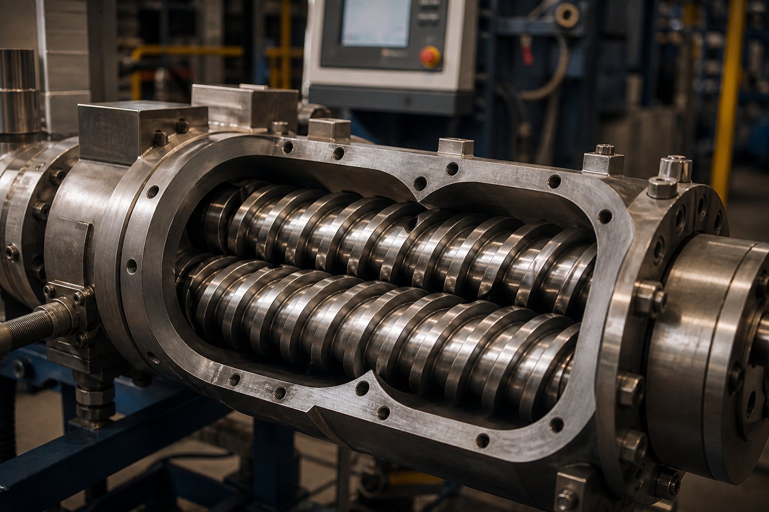
Imagine two identical screws spinning side by side inside a figure-eight-shaped barrel bore, each one the exact same diameter from feed throat to discharge. That mental picture captures the defining geometry of every parallel twin-screw extruder on the market - and it is precisely this equal-diameter, parallel-axis layout that separates it from every other extruder architecture.
Defining the Parallel Twin-Screw Extruder
A parallel twin screw extruder is a polymer processing machine built around two intermeshing screws of identical outer diameter, mounted on parallel center lines within a modular, segmented barrel. Because both screws share the same diameter along their entire length, the barrel bore forms a uniform figure-eight cross-section from inlet to outlet. This stands in direct contrast to conical twin screw designs, where the screws taper from a large feed-end diameter down to a smaller discharge diameter, creating a wedge-shaped compression profile dictated purely by geometry.
The constant cross-section of a parallel twin-screw extruder delivers something conical machines simply cannot: a fully modular platform. Each barrel segment and each screw element can be swapped, rearranged, or replaced independently. You'll notice that this modularity gives process engineers the freedom to configure conveying zones, mixing zones, venting ports, and pressure-building sections in virtually any sequence - all on the same machine frame.
Why the Parallel Configuration Exists
Polymer processing rarely involves a single, unchanging task. One production line might compound glass-fiber-reinforced nylon in the morning and switch to a color masterbatch by afternoon. A different facility might need reactive extrusion capabilities one quarter and simple melt blending the next. The twin screw extruder in its parallel form was engineered to answer exactly this kind of operational flexibility.
Three engineering advantages make this possible. First, the equal-diameter geometry produces a uniform shear distribution across every barrel zone, so processors can predict and control melt behavior with confidence. Second, the modular barrel and screw design lets operators reconfigure the machine for entirely different formulations without purchasing new equipment. Third, the parallel layout scales predictably - a screw profile optimized on a 27 mm lab machine can be translated to a 92 mm production twin screw extruder using well-established volumetric scale-up methods.
The core value of parallel geometry lies in its modularity and scalability: one machine platform, endlessly reconfigurable, with predictable performance from laboratory development through full-scale production.
This flexibility is why the parallel configuration dominates compounding, masterbatch manufacturing, and reactive extrusion worldwide. Yet flexibility alone doesn't explain the machine's performance - the real magic happens at the point where the two screws intermesh, creating a self-wiping action that fundamentally changes how material moves through the barrel.
Parallel vs. Conical Twin-Screw Extruders Compared
If both parallel and conical machines qualify as twin screw extruders, what actually changes when you swap one geometry for the other? The answer goes far deeper than screw shape - it reaches into how compression is generated, how barrels are maintained, and which applications each platform handles best.
Geometric and Mechanical Differences
Picture a conical twin screw extruder and you'll see two screws that taper from a large feed-end diameter down to a noticeably smaller discharge diameter. This taper is the compression engine: as material travels toward the outlet, the shrinking channel volume squeezes it progressively, building pressure through geometry alone. The barrel follows that same taper, forming a single, non-segmented housing that wraps tightly around the converging screws.
A parallel twin-screw extruder takes the opposite approach. Both screws hold a constant diameter from inlet to outlet, so compression is never baked into the hardware. Instead, engineers create compression zones by selecting specific screw elements - kneading blocks, reverse-pitch segments, or reduced-pitch conveying elements - and placing them strategically along the barrel. Swap those elements, and the compression profile changes entirely.
This distinction drives a major maintenance difference. Because conical barrels are one-piece tapered housings, replacing a worn section typically means replacing the entire barrel. Parallel designs bolt together in segments, so a single worn zone can be swapped without disturbing the rest of the machine. For operations running abrasive fillers or corrosive polymers, that modularity translates directly into lower long-term maintenance costs and shorter downtime windows.
Performance and Application Trade-Offs
When you compare the two platforms side by side, the performance differences map neatly onto distinct industrial roles. The conical screw extruder excels in rigid PVC profile and pipe extrusion - applications where gentle, low-shear processing and high discharge pressure matter more than throughput flexibility. Its tapered geometry naturally generates the melt pressure needed to push material through complex dies, and the lower screw speeds typical of conical designs limit thermal exposure for heat-sensitive PVC formulations.
The parallel configuration, by contrast, dominates wherever versatility and throughput scalability are priorities. Compounding engineering plastics, producing masterbatch, running reactive extrusion processes, or handling devolatilization - these tasks demand the high shear, intense mixing, and modular reconfigurability that a double screw extruder in parallel form delivers. Screw speeds on parallel machines can reach 1,200 rpm, and the L/D ratio is easily extended by adding barrel segments, making it practical to scale output without changing the core machine.
| Parameter | Parallel Twin-Screw Extruder | Conical Twin-Screw Extruder |
|---|---|---|
| Screw Geometry | Constant diameter, equal-size screws on parallel axes | Tapered screws converging from large feed to small discharge diameter |
| Barrel Modularity | Segmented, bolt-together barrel sections; individually replaceable | One-piece or minimally segmented tapered barrel |
| Typical L/D Range | 32:1 to 52:1 (extendable by adding segments) | Generally 22:1 to 28:1 (fixed by taper geometry) |
| Shear Profile | High shear; adjustable via screw element selection | Lower shear; controlled by taper and speed |
| Throughput Scalability | High - screw speed up to 1,200 rpm; Do/Di up to 1.8 | Limited - lower speeds and fixed channel volume |
| Primary Applications | Compounding, masterbatch, reactive extrusion, devolatilization, recycling | Rigid PVC profiles, PVC pipe, high-filler compounds |
| Ease of Screw Reconfiguration | Fully modular - individual elements swapped on splined shafts | Integrated one-piece screws; new screw required for different profile |
Cost enters the conversation, too. Conical machines carry a lower initial price tag, making them attractive for dedicated PVC lines where the screw profile will rarely change. Parallel twin screw extruders demand a higher upfront investment, but the ability to reconfigure one machine for multiple formulations often delivers a stronger return over the equipment's lifetime - especially for processors who anticipate evolving product portfolios.
Geometry, however, only tells half the story. The real performance differentiator inside a parallel machine is what happens at the point where one screw flight meets the other - a self-wiping intermeshing action that fundamentally reshapes how polymer melts move, mix, and exit the barrel.
How the Intermeshing Self-Wiping Mechanism Works
What actually happens at the point where one screw flight meets the channel of its partner? This is where the parallel twin-screw extruder earns its reputation - and where its processing behavior diverges sharply from anything a single-screw machine can deliver. The intermeshing self-wiping action is the single most important mechanical principle governing melt quality, residence time control, and changeover efficiency in modern twin screw extrusion. Yet it is rarely explained in a way that gives engineers and buyers a clear mental picture of the physics involved.
Intermeshing Self-Wiping Action Explained
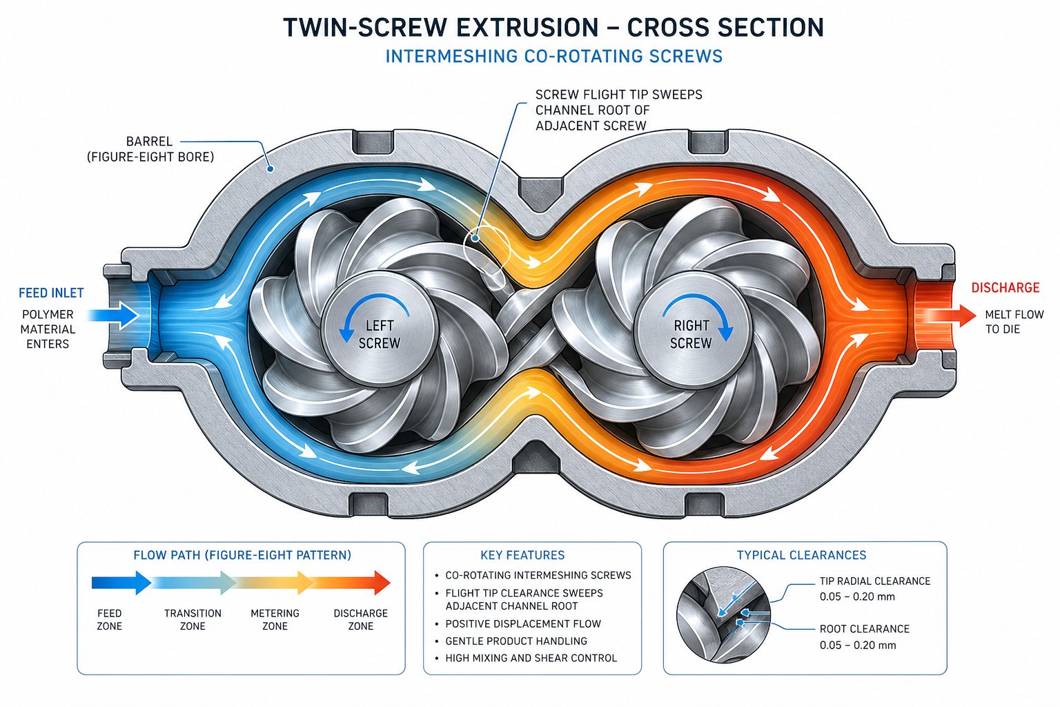
Imagine two screws rotating side by side, their flights overlapping so deeply that the crest of one screw continuously sweeps across the root of the other. As one flight tip passes through its partner's channel, it scrapes the channel surface clean - pushing every trace of polymer forward rather than allowing it to sit, stagnate, and degrade. This is the self-wiping mechanism, and it repeats with every rotation, thousands of times per minute.
Why does this matter so much in practice? Consider what happens without it. In a single-screw extruder, polymer can cling to the screw root and barrel wall for extended, unpredictable periods. Some material races through the barrel quickly while other portions linger in stagnant pockets, accumulating heat and degrading over time. The result is a broad residence time distribution - some of your product has been thermally abused while the rest is barely processed. You end up with gels, discoloration, and inconsistent melt properties.
The twin screws in an intermeshing parallel extruder eliminate that problem at its source. Because every channel surface is continuously wiped clean, there are virtually no dead zones where material can park and overheat. Every polymer molecule follows a similar path through the barrel, experiencing a narrow, tightly controlled residence time distribution. For heat-sensitive polymers like PVC, EVOH, or biopolymers such as PLA, this tight distribution is not just a convenience - it is the difference between a sellable product and scrap.
Color-change operations reveal another practical advantage. When you switch from a dark masterbatch to a lighter formulation, any material left clinging to screw surfaces or trapped in stagnant pockets will contaminate the new product for hours. Self-wiping geometry dramatically accelerates purging because the twin screws physically scrape old material off every internal surface during normal rotation. Changeover times that might take 45 minutes on a non-wiping machine can drop to under 15 minutes - a difference that translates directly into less wasted material and more productive uptime.
Material Conveying and Mixing Mechanisms
Self-wiping geometry is the foundation, but the twin screw extrusion process involves three distinct mechanisms working simultaneously to transport, melt, and homogenize material. Understanding all three helps you see why this platform delivers mixing performance that single-screw machines cannot replicate regardless of screw speed or barrel length.
Drag flow handles forward conveying. As the twin screws rotate, friction between the polymer, the screw flights, and the barrel wall drags material from the feed end toward the die. This is the primary transport mechanism - the engine that moves your formulation through each processing zone. In co-rotating designs, material follows a characteristic figure-eight path as it transfers from one screw channel to the other at the intermeshing region, creating repeated division and recombination of the melt stream.
Pressure flow works in the opposite direction. Restrictive screw elements - reverse-pitch segments, neutral kneading blocks - create localized back-pressure that forces material to slow down and partially recirculate. This back-mixing effect increases the degree of fill in specific barrel zones, which intensifies shear and ensures that kneading elements have enough material to work with. Without pressure flow, kneading blocks would simply push half-empty channels forward with minimal mixing effect.
Distributive and dispersive mixing are generated primarily by kneading elements. Dispersive mixing breaks down agglomerates - think pigment clusters or filler particles - by subjecting them to high shear stress in narrow gaps between kneading disc tips and the barrel wall. Distributive mixing, on the other hand, repeatedly splits and recombines the melt stream to spread additives uniformly throughout the polymer matrix. As research published in AAPS PharmSciTech identifies, five distinct shear regions exist within any twin screw cross-section, each contributing to far more thorough mixing than a single-screw system's drag-dominated flow can achieve.
This three-mechanism interplay is what makes screw extrusion on a twin-screw platform fundamentally different from single-screw processing. A single-screw extruder is essentially a drag-flow pump - it moves material forward and generates pressure, but its mixing capability is inherently limited. The parallel twin-screw extruder, by contrast, gives you independent control over conveying intensity, back-mixing severity, and mixing aggressiveness through the selection and sequencing of individual screw elements.
- Minimal dead zones: Continuous self-wiping prevents material stagnation, virtually eliminating the carbonized particles and gels that plague non-wiping designs.
- Faster material changeover: Self-cleaning screw surfaces reduce purge time and material waste during color or formulation switches.
- Tighter thermal control: Narrow residence time distribution ensures every portion of the melt receives a consistent thermal history, protecting heat-sensitive formulations from localized degradation.
- Better additive dispersion: The combination of dispersive and distributive mixing mechanisms, applied across multiple shear regions between the twin screws, achieves uniform filler and pigment distribution at loadings that single-screw systems simply cannot handle.
These advantages are inherent to the intermeshing geometry itself - but they do not express equally in every machine. The direction those twin screws rotate, whether both spin the same way or in opposing directions, fundamentally reshapes the shear profile, flow pattern, and application range of the extruder.
Co-Rotating and Counter-Rotating Configurations Explained
Two screws, identical in diameter, mounted on parallel axes inside the same barrel - that much stays constant. But reverse the rotation direction of one screw, and you fundamentally change the flow field, shear intensity, and application range of the entire machine. The difference between a co rotating twin screw extruder and its counter-rotating counterpart is not a minor engineering footnote. It determines which materials you can process, how aggressively you can mix, and what throughput ceiling your line will hit.
How Rotation Direction Changes Shear and Flow
In a co-rotating design, both screws spin the same way. Imagine standing at the barrel's cross-section and watching material approach the intermeshing zone: because the screw flights move in unison, polymer is forcibly handed off from the channel of one screw to the channel of the other. The result is a characteristic figure-eight flow path. Material continuously transfers between screws, gets divided, recombined, and exposed to intense shear fields both at the screw-to-screw gap and between each screw tip and the barrel wall. This repeated handoff is what generates the high dispersive mixing that makes co-rotating machines the workhorse of compounding operations worldwide.
The fully intermeshing geometry in co-rotating designs also means the internal volume contains very few dead zones, and the degree of fill can be controlled relatively easily through screw element selection and operating conditions. Self-wiping action is at its strongest here - every flight tip sweeps its partner's channel clean with each rotation. As Technovel's extrusion specialists note, this self-wiping behavior plays a particularly important role in keeping the residence time distribution narrow during reactive extrusion and the processing of thermally sensitive materials.
Counter-rotating screws tell a completely different story. When the two screws spin in opposite directions, their flights converge at the intermeshing zone rather than passing in parallel. Material gets drawn into the gap between the screws and compressed through what engineers call a calendering effect - similar to the nip between two counter-rotating rollers in a calender stack. Instead of the open figure-eight transfer path, material moves forward inside enclosed C-shaped chambers formed between each flight, the barrel wall, and the intermeshing region. These chambers act almost like the teeth of a gear pump, providing tight positive displacement and remarkably stable pressure output.
The trade-off? Shear intensity drops significantly. The calender-like gap compresses and elongates material rather than shearing it aggressively, so heat generation stays low. This is precisely why counter-rotating configurations dominate rigid PVC processing - a material that begins to decompose at temperatures uncomfortably close to its processing window. But this gentler mechanism also imposes a speed ceiling. Counter-rotating screws operating at high rpm generate excessive inter-screw forces that accelerate wear and risk deflection. In practice, co-rotating twin screw extruder machines routinely run at 300-1,200 rpm, while counter-rotating designs typically operate below 150 rpm. That speed limitation directly constrains throughput capacity.
Choosing the Right Configuration for Your Process
Sounds like a clear-cut decision? In many cases, it is - but only once you understand which processing demands align with each configuration's strengths.
A co rotating twin screw extruder earns its place wherever high shear, intense mixing, and throughput flexibility matter most. Compounding glass-fiber-reinforced engineering plastics, producing color masterbatch with demanding pigment dispersion targets, running polymer grafting reactions, or stripping volatiles from moisture-sensitive resins - these applications all depend on the aggressive shear fields and excellent self-cleaning behavior that co-rotating geometry provides. The combination of high screw speed capability, modular screw element design, and wide processing window makes this configuration the standard equipment for modified plastic factories, masterbatch production lines, and large-scale recycling operations.
Counter-rotating machines carve out their niche in a narrower but equally critical set of applications. Rigid PVC pipe and profile extrusion remains the flagship use case. PVC's notoriously low thermal stability demands the low shear, low heat generation, and high-fill operating conditions that only a counter-rotating double screw extruder machine delivers reliably. The stable positive displacement conveying also makes these machines ideal for processing slippery powders - calcium carbonate, talc, or mica formulations - where co-rotating designs struggle with inconsistent feeding and material slip. Direct extrusion of finished profiles, where stable melt pressure and minimal thermal variation matter more than mixing intensity, is another natural fit.
One common and costly mistake worth highlighting: equipping a co-rotating machine for heat-sensitive PVC processing. The high shear and rapid heat buildup will cause PVC decomposition, yellowing, and off-gassing. Equally problematic is attempting fiber-reinforced compounding on a counter-rotating extruder - the weak mixing capacity leaves glass fibers poorly dispersed, producing inconsistent mechanical properties and high reject rates.
| Parameter | Co-Rotating | Counter-Rotating |
|---|---|---|
| Shear Intensity | High - strong dispersive and distributive mixing from screw-to-screw transfer | Low to moderate - gentle calendering effect at intermeshing zone |
| Maximum Screw Speed | 300-1,200 rpm (some high-speed designs exceed 1,200 rpm) | Typically below 150 rpm due to inter-screw force limitations |
| Positive Displacement Capability | Moderate - open figure-eight flow path allows some back-leakage | High - enclosed C-shaped chambers provide gear-pump-like conveying |
| Mixing Quality | Excellent dispersive and distributive mixing; ideal for filler deagglomeration and polymer alloying | Moderate - relies on compressive and elongational deformation rather than high shear |
| Typical Throughput Range | Wide - from laboratory scale (a few kg/hr) to 20+ tons/hr on large production machines | Narrower - constrained by lower speed limits and fixed fill requirements |
| Self-Cleaning Performance | Excellent - fully intermeshing self-wiping geometry minimizes residual material | Moderate - stable residence time but more limited self-cleaning action |
| Primary Industrial Uses | Compounding, masterbatch, reactive extrusion, devolatilization, polymer recycling | Rigid PVC profiles and pipes, heat-sensitive formulations, powder processing, direct extrusion |
The choice between co rotating and counter rotating twin screw extruder configurations ultimately comes down to one question: what does your material demand? High-filler dispersion, reactive chemistry, or high-volume compounding points decisively toward co-rotating. Heat-sensitive polymers, powder-heavy formulations, or stable-pressure direct extrusion calls for counter-rotating. Either way, the parallel twin-screw platform accommodates both - and the real versatility of each configuration only becomes apparent when you look at what sits inside the barrel: the modular screw elements and barrel segments that let engineers tailor every zone to a specific processing function.
Modular Barrel Sections and Screw Element Design
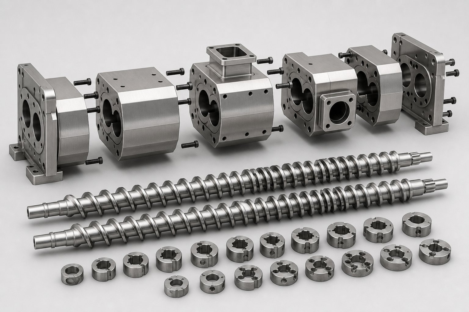
Think of a parallel twin-screw extruder the way you'd think of a high-performance building-block system. Every barrel section and every screw element is an independent, interchangeable module. Rearrange them, and you've effectively built a different machine - without buying one. This modular design philosophy is what separates the parallel platform from virtually every other extrusion architecture, and it is the reason a single compounding twin screw extruder can handle glass-fiber-reinforced nylon on Monday and switch to a calcium-carbonate-loaded masterbatch by Wednesday.
The modularity works on two parallel tracks: the barrel sections that form the outer housing, and the screw elements that ride on splined shafts inside it. Understanding both - and how they interact - is essential for anyone configuring, troubleshooting, or purchasing twin screw and barrel components.
Barrel Section Types and Their Functions
A modern parallel twin-screw extruder barrel is not a single tube. It is a series of individual barrel segments, typically four to five screw diameters in length each, bolted together end to end and precisely aligned. Each segment can serve a different processing function depending on what ports or features are machined into it. Swap one segment out, and you change the machine's capability in that zone without disturbing anything upstream or downstream.
Here are the most common barrel section types you'll encounter:
- Solid closed barrel: A fully enclosed segment with no openings. Used in conveying, melting, and mixing zones where the material must remain sealed under pressure and controlled temperature.
- Feed barrel (open top): Features a machined opening at the top for the main feed port. Typically the first segment in the barrel train, it receives resin pellets, powders, or pre-blended formulations from gravimetric or volumetric feeders.
- Vented barrel: Includes an atmospheric or vacuum vent port for devolatilization. Positioned downstream of a melt seal created by reverse screw elements, it allows moisture, trapped air, or volatile byproducts to escape the melt stream without disrupting forward flow.
- Side-feed barrel: Equipped with a lateral port for introducing fillers, reinforcements, or secondary polymers after the base resin has already melted. This is critical for shear-sensitive additives like long glass fibers, which would break apart if fed at the main throat and subjected to the full melting zone.
- Liquid injection barrel: Contains a port fitted with an injection nozzle for introducing liquid additives, peroxides, coupling agents, or water for steam-assisted devolatilization directly into the melt.
The beauty of this arrangement is combinatorial flexibility. A twin screw compounding extruder running a 40:1 L/D barrel train might use ten individual segments. An operator processing hygroscopic nylon could place vented barrels at zones six and nine for two-stage devolatilization. A masterbatch producer might install a side-feed barrel at zone five for downstream pigment addition. The same machine frame accommodates both configurations - you just unbolt, rearrange, and retighten.
Barrel longevity depends heavily on liner materials, and this is where material selection becomes a serious engineering decision. Abrasive fillers like glass fiber, calcium carbonate, and talc erode barrel bores relentlessly. Corrosive polymers - fluoropolymers, certain flame-retardant compounds - attack standard steel liners chemically. To combat this, barrel segments are manufactured with wear-resistant liners matched to the severity of the application:
- Nitrided steel: A cost-effective baseline treatment suitable for unfilled or lightly filled polymer processing.
- Bimetallic alloys: A centrifugally cast wear layer (typically iron-boron or nickel-based alloys) bonded to the barrel bore. Standard for moderate to high abrasion environments, including most mineral-filled compounding operations.
- Tungsten carbide coatings: The most aggressive wear protection available, reserved for extreme applications such as high glass-fiber loadings or ceramic-filled engineering plastics.
For operations running abrasive or corrosive formulations, sourcing barrel segments with the right metallurgy is not optional - it directly controls maintenance intervals and total cost of ownership. Suppliers like NANHAIYA specialize in replacement and custom parallel twin-screw barrels engineered for high-wear processing environments, offering barrel segments with liner materials matched to specific wear conditions. When your process involves heavy filler loading or chemically aggressive melts, custom barrel configurations from a specialist supplier can be specified to align with your particular screw element layout and throughput demands.
Screw Element Configuration Strategy
If barrel segments define where things happen along the extruder, screw elements define what happens. Every screw element slides onto a common splined shaft and locks into position, creating a continuous screw profile that can be disassembled and reconfigured in a matter of hours. As NC State Extension's research on screw profile design emphasizes, configuring a screw is a blend of art and science - no single gold standard exists because every material exhibits unique flow properties under different shear and temperature conditions.
Three primary element families form the building blocks of every screw configuration:
Conveying elements handle forward transport. These are helical flight elements available in multiple pitches. A large-pitch element like an SK 40/40 moves a high volume of material quickly with minimal shear input - ideal for the feed zone where you want rapid, gentle intake. A tighter-pitch element such as an SE 20/20 slows material down, increases the degree of fill, and builds pressure - exactly what you need approaching the die or a melt seal. Think of pitch selection as a throttle: wide open for fast conveying, progressively tightened as you want to compress and pressurize the melt.
Kneading blocks are where mixing happens. Each kneading block consists of a series of lobed discs stacked at offset angles - typically 30, 45, 60, or 90 degrees relative to each other. The offset angle and disc width determine whether the block favors distributive mixing (spreading additives evenly throughout the melt) or dispersive mixing (breaking apart agglomerates under high shear stress). Narrow-disc kneading elements like KP configurations provide gentler distributive action, while wide-disc KBW elements generate aggressive dispersive shear. Forward-staggered kneading blocks maintain some conveying action; neutral 90-degree stagger stops conveying entirely, maximizing residence time and energy input in that zone. Reverse-staggered blocks actively push material backward, creating a melt seal and intense back-pressure.
Reverse elements complete the toolkit. These are conveying elements with opposite-hand pitch - left-handed on a right-hand screw - that deliberately oppose forward flow. Placed strategically, they create the melt seals required upstream of vent ports (preventing melt from escaping through the vent) and generate the back-pressure needed to ensure kneading blocks operate in fully filled conditions. Their length is typically kept shorter than one screw diameter to avoid excessive pressure peaks and localized overheating.
In practice, configuring a twin screw auger profile means sequencing these three element families to match your process requirements zone by zone. A typical compounding profile might start with large-pitch conveying elements in the feed section, transition into a kneading block series for melting and initial mixing, follow with a reverse element to create a melt seal before a vent port, resume with conveying elements to transport melt past the vent, add a second kneading section for final dispersive mixing, and finish with tight-pitch conveying elements to build die pressure. Every element choice influences shear history, residence time, and melt temperature - which is why experienced process engineers treat screw configuration as one of the most consequential decisions in the entire extrusion setup.
The interplay between barrel sections and screw elements is what gives the parallel platform its unmatched versatility. But configuring modular hardware is only half the equation - the ratio of barrel length to screw diameter, and the process parameters that govern energy input, ultimately determine whether that hardware delivers efficient, high-quality output or wastes energy on thermal degradation.
L/D Ratio, Process Parameters, and Energy Efficiency
Every parallel twin-screw extruder has a specification that appears on the first line of its data sheet: the L/D ratio. Engineers reference it constantly, procurement teams compare it across quotes, and process developers use it to judge whether a machine can handle a particular formulation. Yet surprisingly few resources explain what different L/D values actually mean in practice - or how they connect to the energy efficiency metrics that ultimately drive operating costs.
What L/D Ratio Means for Process Capability
The L/D ratio is simply the total barrel length divided by the screw diameter. A twin-screw extruder machine with 40 mm screws and a barrel length of 1,600 mm has a 40:1 L/D. Straightforward math - but the implications for processing capability are enormous, because every unit of L/D represents available real estate for a specific processing task: feeding, melting, mixing, venting, or pressure building.
Think of L/D as the number of rooms in a house. A smaller house forces you to combine functions - the kitchen doubles as the dining room. A larger house lets every activity have its own dedicated space. The same logic applies to screw extruders. A short barrel compresses multiple processing steps into shared zones, while a longer barrel gives each step its own dedicated segment.
Here is how the most common L/D ranges map to real-world applications:
- 32:1 - Suited for straightforward tasks like simple melt blending, color concentrate production, or processing thermally sensitive materials that benefit from shorter residence times. There is enough barrel length for feeding, melting, basic mixing, and pressure building, but limited room for additional operations like devolatilization or multi-stage filler addition.
- 40:1 - The versatile general-purpose ratio. Most compounding operations - engineering plastics, mineral-filled formulations, standard masterbatch - run comfortably at this length. You get enough zones for a full melting section, one or two kneading stages, a vent port, and a dedicated pressure-building zone before the die. Industry data from the Plastics Technology Handbook 2025 confirms this range as the most commonly specified for medium to large production extruders.
- 48:1 to 52:1 - Reserved for complex, multi-step processes. Reactive extrusion demanding extended residence time, formulations requiring two-stage devolatilization under vacuum, or heavily filled compounds needing downstream side-feeding followed by additional dispersive mixing - these applications consume barrel real estate rapidly. An extruder for polymer grafting reactions, for example, may need separate zones for peroxide injection, reaction residence, unreacted monomer stripping, and final homogenization, all before reaching the die.
Longer L/D ratios are not automatically better, though. Every additional barrel segment adds residence time and cumulative energy input. For thermally sensitive resins - PVC, certain biopolymers, or shear-degradable elastomers - that extra time at elevated temperature can push the material past its degradation threshold. The goal is always to use enough L/D for the process to complete its required steps, and no more.
Energy Efficiency and Specific Energy Consumption
L/D determines how much barrel you have. But how efficiently you use that barrel comes down to a metric called specific energy consumption, or SEC, measured in kWh/kg. It represents the total energy the extruder motor delivers to each kilogram of material passing through the machine - and it is arguably the single most important number for understanding both process quality and operating cost.
Where does that energy actually go? The extruder's drive motor transmits torque through the gearbox to the screws, and the screws convert that mechanical energy into shear heating within the polymer melt. This shear energy input from the screws is the dominant energy source in twin-screw compounding - barrel heaters contribute comparatively little once the melt zone is established. SEC captures this reality in a single, comparable number.
Four interacting parameters determine where your SEC lands:
- Screw speed: Higher rpm drives more mechanical energy into the melt. Greater screw speeds produce higher melt temperatures through viscous dissipation, particularly in kneading zones where shear rates peak.
- Throughput rate: Increasing feed rate at constant screw speed reduces SEC because each kilogram of material shares the motor's energy output with a larger total mass. However, pushing throughput too high can starve mixing zones and compromise dispersion quality.
- Screw element configuration: Aggressive kneading block sequences consume more energy than gentle conveying profiles. Every reverse element and high-offset kneading disc adds to the total energy absorbed by the melt.
- Barrel temperature profile: Setting barrel zones significantly below the polymer's natural processing temperature forces the screws to do more work, raising SEC. Conversely, overheated barrels can reduce melt viscosity to the point where kneading elements lose their shear effectiveness, paradoxically requiring higher screw speeds to achieve the same mixing result.
Lab-scale compounding trials illustrate how these variables interact in practice. Testing on a Thermo Scientific Process 11 extruder at 1 kg/h and 200 rpm yielded a specific energy of approximately 0.155 kWh/kg (559 kJ/kg). Scaling that process to a 16 mm compounder at a Schuler-rule-predicted 3 kg/h initially produced significantly lower SEC - only after adjusting the feed rate down to 2.5 kg/h did the specific energy match the lab-scale baseline. That kind of iterative tuning is exactly what production engineers face every time they commission a new formulation.
The ideal specific energy consumption balances just enough mixing energy to achieve complete dispersion and homogenization against the thermal degradation risk that comes from putting too much mechanical work into the polymer melt.
Optimizing SEC is not an academic exercise - it has direct financial consequences. An extruder running at 0.20 kWh/kg instead of an optimized 0.15 kWh/kg on a line producing 2,000 kg/h wastes 100 kW continuously. Over a three-shift operation running 7,000 hours per year, that adds up to 700,000 kWh of unnecessary energy consumption. At industrial electricity rates, the cost difference can reach tens of thousands of dollars annually on a single line. Multiply that across multiple screw extruders in a compounding plant, and energy optimization becomes one of the most impactful cost-reduction levers available.
These process parameters and energy considerations shape how efficiently any given formulation runs on the equipment. But parameters only matter when they are applied to a specific application - and the parallel twin-screw platform serves a remarkably diverse range of industries, each with its own processing demands and performance benchmarks.
Key Industry Applications of the Twin Screw Plastic Extruder
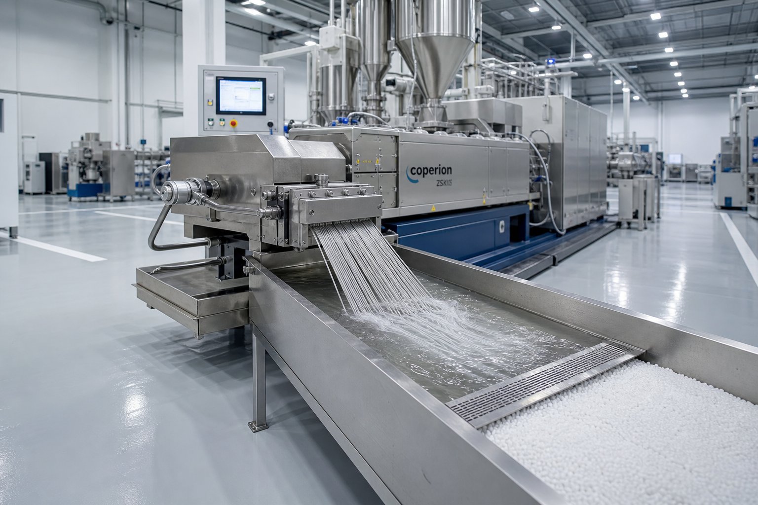
Every barrel zone, screw element, and process parameter discussed so far exists for one reason: to serve a specific industrial outcome. A beautifully configured compounding twin screw extruder means nothing if it doesn't solve a real production challenge. So where does this technology actually earn its keep? The answer spans far more industries than most people expect - from high-volume polymer compounding plants to pharmaceutical cleanrooms and food processing facilities. Each application exploits a different combination of the platform's strengths: self-wiping geometry, modular configurability, precise thermal control, and scalable throughput.
Rather than listing applications generically, let's rank them by market adoption and explain what makes the parallel twin-screw extruder the preferred platform in each case.
- Polymer compounding
- Masterbatch manufacturing
- Plastic recycling and pelletizing
- Reactive extrusion
- Pharmaceutical and food processing
Polymer Compounding and Masterbatch Production
Imagine blending a base polyamide resin with 30% short glass fiber, a heat stabilizer package, a UV absorber, and a processing lubricant - all in a single continuous pass, at throughputs exceeding several tons per hour. That is a routine Tuesday for a plastic twin screw extruder running a compounding operation. Polymer compounding represents the largest single application category for parallel machines, and for good reason: no other platform delivers the combination of dispersive mixing intensity, distributive homogeneity, and throughput flexibility that compounding demands.
The twin screw extrusion process excels here because each additive presents a different mixing challenge. Mineral fillers like calcium carbonate and talc arrive as agglomerates that need dispersive shear to break apart. Reinforcing fibers need to be incorporated gently enough to preserve length while still achieving uniform distribution. Stabilizers and lubricants are added in small percentages and must be spread evenly across the entire melt matrix. The modular screw profile handles all of these requirements simultaneously - aggressive kneading blocks upstream for filler deagglomeration, side-feeding downstream for fiber preservation, and tight-pitch conveying elements to build die pressure for clean pelletizing.
Masterbatch production places even tighter demands on dispersion quality. When you produce a color masterbatch, every pigment particle must be fully deagglomerated and uniformly distributed throughout the carrier resin. A single undispersed pigment cluster creates visible specks in the final molded or extruded part - an immediate quality rejection. The self-wiping geometry of the parallel compounding extruder proves critical here, preventing pigment buildup on screw surfaces that would later shed as contamination during color changes. Masterbatch producers running multiple color switches per shift rely on rapid purging behavior to minimize transition waste, and the tight residence time distribution ensures consistent color strength from the first pellet to the last.
Recycling, Pelletizing, and Specialty Applications
Plastic recycling has emerged as one of the fastest-growing application areas for twin screw extruder plastic processing lines. Post-industrial recycling - reprocessing edge trim, start-up scrap, or off-spec material generated within a manufacturing facility - is a well-established practice. The corotating twin-screw platform fits naturally because the feedstock is relatively clean, and the machine's venting capability removes residual moisture without a separate drying step. As Plastics Technology details, PET and PLA edge reclaim systems use multi-stage vacuum venting on twin-screw lines to bypass the drying step entirely, minimizing IV loss from hydrolysis while allowing higher percentages of edge trim back into the sheet line.
Post-consumer recycling presents greater challenges. Contaminated feedstocks - mixed polyolefins, residual labels, trace metals - demand filtration systems and sometimes single-screw extruders for high-pressure pumping. However, when the goal shifts from simple remelting to value-added compounding, the twin screw plastic extruder reclaims its advantage. Blending recycled HDPE or PP with mineral fillers at loadings up to 80%, dispersing trace contaminant polymers, and stripping residual moisture all happen more effectively on a co-rotating platform. In pelletizing operations, the extruder pairs with a screw extruder granulator system - typically a strand pelletizer or underwater die-face cutter - to convert compounded melt into uniform pellets ready for downstream molding or extrusion.
Reactive extrusion occupies a more specialized but technically demanding niche. Here the twin-screw barrel becomes a continuous chemical reactor. Polymer grafting reactions - maleic anhydride onto polyolefin backbones, for example - require precise injection of peroxide initiators, controlled residence time in reaction zones, and efficient stripping of unreacted monomers through vacuum venting. The modular barrel and screw design allows engineers to configure dedicated reaction, devolatilization, and cooling zones in sequence. Controlled-radical polymerization, silane crosslinking, and chain extension of recycled PET are all performed commercially on parallel twin-screw platforms, leveraging the tight thermal control and narrow residence time distribution that prevent runaway reactions and side-product formation.
Pharmaceutical processing represents the newest frontier. Hot melt extrusion (HME) uses the twin-screw platform to create amorphous solid dispersions - intimately mixing poorly soluble active pharmaceutical ingredients with thermoplastic polymer carriers to dramatically improve drug bioavailability. Research published in AAPS PharmSciTech documents how the first FDA-approved melt-extruded drug product, Rezulin, was developed on a 34 mm laboratory twin-screw extruder and scaled to 50 mm production equipment with no batch failures over 500 hours of continuous operation. The hot melt extruder's ability to process without solvents or water eliminates expensive drying steps, and the continuous manufacturing mode provides the tight process control that regulatory frameworks like the FDA's PAT initiative actively encourage. Products ranging from Kaletra (HIV treatment) to NuvaRing (contraceptive device) are manufactured using twin-screw melt extrusion, and the list of approved products continues to grow.
Food processing rounds out the application landscape. Twin-screw extruders texturize plant proteins, produce snack foods, and process starch-based materials. The same self-wiping action that prevents polymer degradation also prevents food ingredients from charring on screw surfaces - a food safety requirement as much as a quality one. While food applications use somewhat different screw element geometries and barrel materials than plastics operations, the underlying platform is identical: modular, configurable, and scalable from pilot-plant development batches to full production volumes. In some food pelletizing operations, the screw extruder granulator setup mirrors plastics applications almost exactly, producing uniform granules of flavored or fortified food products for further processing.
Across all five application tiers, one pattern repeats. The parallel twin-screw extruder earns its position not through brute force, but through adaptability - the same machine frame, reconfigured with different screw elements, barrel sections, and downstream equipment, serves radically different industries. That adaptability, however, raises an important practical question: how do you take a formulation developed on a small lab machine and reproduce it faithfully on a production-scale extruder ten times its size?
Scaling from Lab-Scale to Production Twin-Screw Extruders
A formulation that runs beautifully on a 26 mm laboratory twin screw extruder does not automatically behave the same way when you bolt an identical screw profile onto a 92 mm production machine. The geometry scales up. The physics do not follow in lockstep. This gap between development-scale success and production-scale reality is one of the most consequential - and most underestimated - challenges in twin-screw processing.
Lab-Scale Extruders and Process Development
Every new formulation starts small. A lab scale twin screw extruder - typically 10 to 27 mm in screw diameter - gives process engineers the ability to screen raw materials, iterate on screw configurations, and dial in temperature profiles without consuming tons of expensive resin. A benchtop twin screw extruder in the 15-16 mm class might process only 1 to 5 kg/h, yet it replicates the same fundamental shear and mixing mechanisms that a full-production machine uses: intermeshing self-wiping geometry, modular kneading blocks, staged barrel zones, and controllable residence time distribution.
This fidelity is what makes the lab scale extruder such a powerful development tool. You are not running a rough approximation of your production process - you are running a geometrically similar miniature version. The screw element families (conveying, kneading, reverse) are functionally identical to their production-scale counterparts, and the L/D ratio can be matched precisely. A case study published in Plastics Technology illustrates this directly: a masterbatch formulation was first optimized on a 26 mm co-rotating, fully intermeshing lab scale extruder at an L/D of 44:1, producing pellets with a specific mechanical energy (SME) of 0.083 kWh/kg. That SME value - not just the screw speed or temperature profile - became the critical reference point for every subsequent scale-up step.
Small-batch production is another practical use case. Pharmaceutical hot melt extrusion trials, specialty additive development, and experimental polymer blends often require only kilograms of finished material for downstream testing. A laboratory twin screw extruder delivers those small quantities under tightly controlled, production-representative conditions - something a batch mixer or internal kneader simply cannot replicate.
Scale-Up Principles and Common Challenges
Scaling from a 26 mm lab machine to a 92 mm production extruder means multiplying the screw diameter by a factor of roughly 3.5. Sounds straightforward? Here is where the physics get uncomfortable. Technovel's extrusion engineering team frames the challenge clearly: scale-up theory offers two limiting models, and real-world operations always land somewhere between them.
The cubic law treats the extruder interior as a three-dimensional volume. Since free volume scales with the cube of the screw diameter (Q ∝ D³), throughput theoretically increases by a factor of D-ratio cubed. Scaling from 15 mm to 60 mm screws - a diameter ratio of 4 - would predict a 64-fold throughput increase. This approach maximizes production capacity, but it assumes constant screw speed and shear rate. In practice, the higher peripheral speed on larger screws generates substantially more shear heating, pushing melt temperatures beyond acceptable limits for many polymers.
The square law takes the opposite perspective. It treats the extruder as a two-dimensional heat transfer system, recognizing that barrel surface area - the primary avenue for heating and cooling - scales only with the square of the diameter (Q ∝ D²). The same 15-to-60 mm jump now predicts only a 16-fold throughput increase. You sacrifice capacity, but you preserve the thermal history and mixing state that your lab-scale process validated.
Why can't you just match both? Because of a geometric reality that no amount of process optimization can eliminate: as screw diameter grows, the internal volume increases with D³ while the barrel surface area increases with only D². The area-to-volume ratio shrinks with every step up in machine size. Barrel-based heating and cooling become progressively less effective at influencing the bulk melt temperature. The same temperature setpoints and screw speeds that worked on the lab machine will not reproduce the same thermal history on the production extruder.
The Plastics Technology case study demonstrates this vividly. When optimized conditions from the 26 mm extruder were directly applied to a 40 mm machine, the process exhibited severe pressure fluctuations and visible phase separation. The SME dropped to 0.055 kWh/kg - a 34% shortfall. Only after redesigning the screw profile, lowering the temperature setpoints, and adjusting the screw speed did SME recover to 0.079 kWh/kg, and stable operation resumed. Scaling further to 92 mm produced even more dramatic failures: unmelted pellets discharged through the diverter valve, with SME collapsing to just 0.026 kWh/kg. A complete overhaul of the screw design and feeding configuration was required to bring SME back to 0.086 kWh/kg and achieve reliable production.
The lesson? Direct replication of lab-scale operating conditions onto production equipment is not a scale-up strategy. It is a recipe for wasted material and lost production days.
Successful scale-up requires engineers to match a defined set of critical parameters between machines, adjusting hardware and operating conditions as needed to hit those targets at the new diameter:
- Specific mechanical energy (SME): The single most reliable scale-up reference. Matching SME in kWh/kg between lab and production ensures equivalent energy input per unit mass, which directly influences dispersion quality and melt homogeneity.
- Residence time distribution: The time each polymer molecule spends inside the barrel must remain comparable. Longer barrels and larger free volumes at production scale tend to broaden residence time unless screw speed and fill ratio are adjusted accordingly.
- Shear history: The cumulative shear stress and shear rate experienced by the material through all processing zones. Changes in screw tip speed at larger diameters alter peak shear rates even when screw rpm stays constant.
- Fill ratio: The percentage of available free volume occupied by material in each barrel zone. Underfilling kneading zones on larger machines starves mixing elements and reduces energy transfer to the melt.
- Thermal profile equivalence: Because the area-to-volume ratio drops with increasing diameter, barrel temperature setpoints almost always need recalibration - typically cooler profiles on larger machines to compensate for reduced heat removal capacity.
- Feed behavior: Bulk density changes, powder fluidization effects, and bridging tendencies in hoppers can behave differently at higher feed rates. Gravimetric feeder calibration and feed throat geometry sometimes require adjustment at production scale.
Engineers experienced in scale-up treat the process as iterative, not formulaic. The cubic and square laws provide upper and lower bounds for expected throughput. SME provides the quality anchor. Everything else - screw configuration, barrel temperatures, screw speed, feed rate - becomes a variable that gets tuned until the production machine delivers both the target throughput and the target SME simultaneously.
There is also a conservative alternative worth mentioning. When material quality reproducibility is the absolute top priority - pharmaceutical applications, for instance - some operations bypass the scale-up problem entirely by installing multiple lab-scale or pilot-scale extruders running in parallel. This preserves shear history, residence time, and thermal conditions exactly, at the cost of higher capital expenditure and floor space.
Whether you scale up to a single large machine or multiply smaller ones, the mechanical reality of running any parallel twin-screw extruder at production intensity eventually shows up in the same place: wear on your screws and barrel bores. Understanding how that wear develops - and when to act on it - is what separates operations that maintain consistent output from those that gradually lose quality without realizing why.
Maintenance, Wear Patterns, and Barrel Replacement for Twin-Screw Extruders
A parallel twin-screw extruder doesn't announce that it's wearing out. It whispers. Motor load creeps up by a few percent over several months. Pellet quality drifts slightly off-spec - not enough to trigger an immediate reject, but enough to generate customer complaints if it continues unchecked. By the time an operator notices visible scoring on a screw flight or measures a bore diameter that's clearly oversized, the machine has been running inefficiently for hundreds of hours. Recognizing wear early, understanding what causes it, and knowing when to replace components are skills that separate well-managed production lines from operations bleeding money through neglect.
Common Wear Patterns in Screws and Barrels
Every material you push through a twin-screw extruder is simultaneously trying to destroy it. The severity depends on what you're processing, but the mechanisms fall into three well-documented categories - and most production environments deal with at least two of them simultaneously.
Abrasive wear is the most common culprit. Mineral fillers like calcium carbonate, talc, and especially glass fiber act as fine sandpaper against barrel bores and screw flight surfaces. As Adams Engineers' maintenance reference explains, these hard particles continuously abrade the metal surface, gradually enlarging the barrel bore and reducing screw flight outer diameters. Glass fiber compounds are particularly aggressive - the fibers are harder than most barrel liner materials and generate wear patterns concentrated in kneading zones and downstream conveying sections where melt pressure forces fiber-laden polymer against the barrel wall at maximum intensity.
Adhesive wear results from metal-to-metal contact. When screw flight tips run against the barrel bore under high load - caused by misalignment, excessive screw deflection, or improper operating conditions - material transfers between the two metal surfaces. You'll see it as galling marks, localized scoring, or rough patches on otherwise smooth surfaces. This type of damage accelerates rapidly once it starts because the roughened surface increases friction, which increases heat, which increases deflection, which causes more contact. Catching adhesive wear early is critical.
Corrosive wear presents a different challenge entirely. Chemically aggressive polymers - fluoropolymers, flame-retardant compounds containing halogenated additives, and even PVC releasing hydrochloric acid during processing - attack barrel and screw metallurgy at the molecular level. ENTEK's metallurgy specialists note that corrosive wear is indicated by pitted surfaces and the rounding-off of sharp corners, distinguishing it visually from the smooth, even material loss that characterizes abrasive wear. In extreme cases - fluoropolymer processing, for example - exotic alloys like Inconel or Hastelloy may be required, though their low hardness values (Rockwell C 35 or less) mean they sacrifice abrasion resistance to gain corrosion protection.
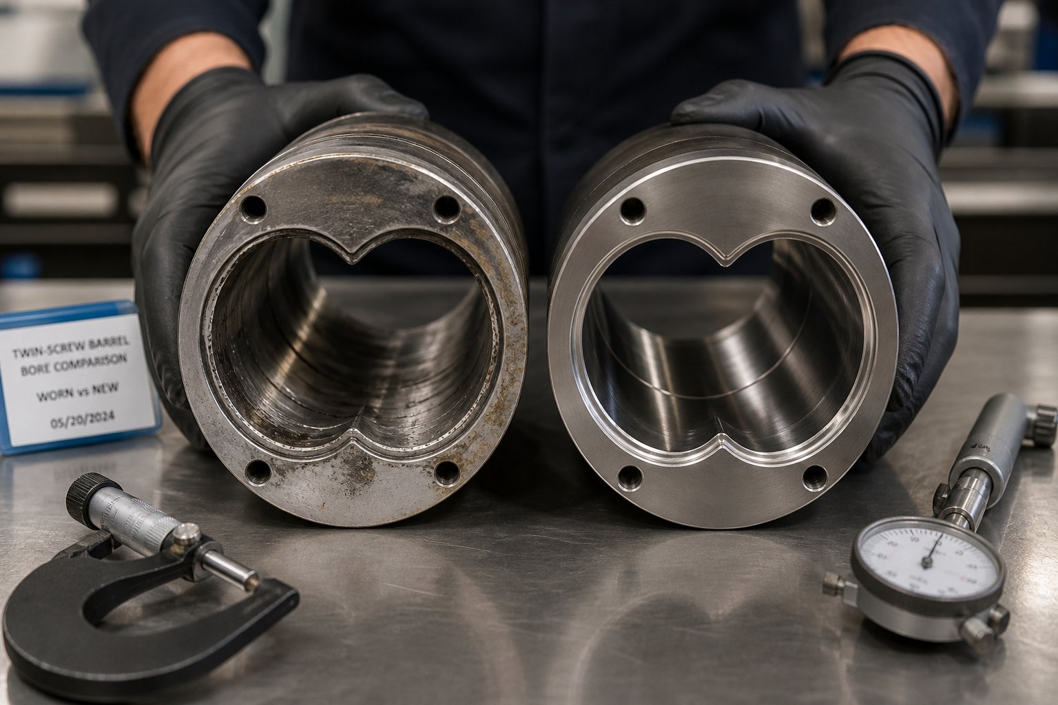
How does wear actually manifest in a parallel twin-screw barrel? It starts with bore diameter enlargement. As the barrel bore widens, the tight clearance between screw flight tips and barrel wall - the gap responsible for self-wiping action and dispersive mixing - opens up. Material begins to leak past the screw tips instead of being sheared and compressed. Mixing efficiency drops. The self-wiping mechanism weakens, allowing material to stagnate in zones that were previously swept clean with every rotation. Energy consumption increases because the screws must work harder to convey and pressurize material through a progressively leakier system. Product quality degrades in ways that are maddeningly gradual: slightly coarser pigment dispersion, marginally inconsistent melt flow index, or a slow uptick in gel count that only becomes obvious when you compare data over weeks or months.
Replacement Strategies and Sourcing Quality Barrels
When should you actually pull the trigger on replacement? The answer depends on your process tolerance, but a structured inspection program removes the guesswork.
Bore gauging is the primary diagnostic tool. Using a telescoping bore gauge or an electronic bore measurement system, technicians measure the internal diameter at multiple points along each barrel segment. Industry guidelines from SPI provide dimensional thresholds indicating when a component has worn beyond acceptable limits. Comparing current measurements against original specifications - and tracking the rate of change over time - creates a wear profile that predicts remaining service life. This predictive approach lets you schedule replacements during planned downtime rather than reacting to failures that halt production mid-run.
Visual inspection of barrel liner condition supplements the numbers. Pitting, cracking, or delamination of bimetallic liners signals that the wear protection layer has been compromised, and continued operation will expose the softer base metal to accelerated erosion. Screw elements deserve the same scrutiny - measure flight outer diameters with a micrometer across multiple points, and check kneading block tips for chipping or rounding.
Replacement intervals vary dramatically depending on processing severity. Operations compounding unfilled or lightly filled polymers may run thousands of hours between replacements. Glass-fiber-reinforced compounds at 30-40% loading can consume a set of barrel liners in a fraction of that time. Corrosive formulations add another dimension of unpredictability. The only reliable strategy is data: measure regularly, track trends, and replace proactively.
Recognizing the warning signs before they become production crises is equally important. Watch for these indicators that barrel or screw element replacement is overdue:
- Increased motor load: Rising amperage at constant throughput and screw speed means the screws are fighting harder to convey material through enlarged clearances - a direct consequence of bore wear.
- Declining product quality: Coarser filler dispersion, inconsistent color strength, increasing gel count, or wider melt temperature variation all point to diminished mixing efficiency from worn self-wiping geometry.
- Visible wear marks: Scoring, grooves, or polished streaks on screw flights and barrel bores visible during routine inspections indicate active metal removal that will only accelerate.
- Inconsistent output: Fluctuating die pressure, unstable strand formation, or surging pellet weight variation suggest that the screws can no longer maintain stable positive conveying - often the final symptom before a forced shutdown.
Matching barrel metallurgy to specific wear conditions is where sourcing decisions become engineering decisions. A barrel segment destined for a kneading zone processing 40% glass-fiber-filled nylon needs a completely different liner material than one used in a feed section handling unfilled polypropylene. As ENTEK's experience confirms, the industry has shifted heavily toward Hot Isostatic Pressed (HIP) alloy liners and replaceable liner construction, which allow worn liners to be swapped out while reusing the barrel body - including its cooling passages, thermocouple wells, and mounting features - indefinitely. This approach reduces long-term ownership costs significantly compared to discarding entire barrel segments.
For twin screw extruder manufacturers and operators running high-wear applications, sourcing replacement barrels from a supplier that understands parallel twin-screw geometry and process-specific wear demands is not a convenience - it is a cost-control strategy. NANHAIYA serves exactly this role, providing replacement and custom parallel twin-screw barrels for compounding producers, masterbatch manufacturers, recycling plants, and pelletizing operations. Their barrel segments can be specified with liner materials matched to the abrasion severity or chemical aggressiveness of your particular process - whether you're running high-calcium-carbonate filler loads that demand tungsten-carbide-grade wear protection or processing flame-retardant formulations that require corrosion-resistant alloy liners. Having a specialist twin-screw extruder manufacturer for barrel components means your replacement parts arrive engineered for your conditions, not built to a generic specification that may fall short in the zones where wear is most severe.
One final principle that experienced operators live by: always document your wear data. Record bore measurements, screw element OD readings, motor load trends, and product quality metrics at consistent intervals. Over time, this data set becomes your most valuable maintenance tool - it tells you not just when components need replacing, but which barrel zones and screw element positions wear fastest in your specific process. That knowledge lets you stock the right spares, budget accurately for replacements, and specify barrel metallurgy with confidence when ordering from twin-screw extruder manufacturers who offer custom configurations. The parallel twin-screw extruder's modularity makes component replacement straightforward. Your maintenance program determines whether that replacement happens on your schedule or the machine's.
Frequently Asked Questions About Parallel Twin-Screw Extruders
1. What is the difference between a parallel and a conical twin-screw extruder?
A parallel twin-screw extruder uses two equal-diameter screws on parallel center lines inside a modular, segmented barrel, achieving compression through interchangeable screw elements. A conical twin-screw extruder uses tapered screws that narrow from the feed end to the discharge, generating compression through fixed geometry. The parallel design offers greater modularity, higher throughput scalability with screw speeds up to 1,200 rpm, and L/D ratios from 32:1 to 52:1. Conical machines suit dedicated PVC processing lines thanks to their gentler shear and lower cost, but they lack the reconfigurability that parallel platforms provide for diverse compounding, masterbatch, and reactive extrusion tasks.
2. How does the self-wiping mechanism in a parallel twin-screw extruder improve product quality?
The self-wiping mechanism works by having each screw flight continuously sweep across the channel of its partner screw during rotation. This action prevents polymer from stagnating in dead zones, where it would overheat and degrade into gels or carbonized particles. The result is a narrow residence time distribution, meaning every portion of the melt receives a consistent thermal history. This is especially critical for heat-sensitive materials like PVC, PLA, and EVOH. Additionally, self-wiping surfaces dramatically reduce purge time during color or formulation changes - often cutting changeover from 45 minutes down to under 15 minutes, which saves both material and productive uptime.
3. When should I choose a co-rotating twin-screw extruder over a counter-rotating one?
Choose a co-rotating configuration when your process demands high dispersive mixing, aggressive filler deagglomeration, or high throughput. Co-rotating machines excel at polymer compounding, masterbatch production, reactive extrusion, and devolatilization, running at speeds from 300 to 1,200 rpm. Counter-rotating extruders are better suited for heat-sensitive materials like rigid PVC, powder-heavy formulations, and direct profile extrusion where gentle shear, low heat buildup, and stable positive displacement matter more than mixing intensity. Using the wrong configuration - such as processing PVC on a co-rotating machine - risks thermal degradation and off-gassing.
4. How do I know when my twin-screw extruder barrel needs replacement?
Watch for four key warning signs: rising motor amperage at constant throughput, declining product quality such as coarser dispersion or increasing gel count, visible scoring or grooves on screw flights and barrel bores during inspections, and inconsistent output including fluctuating die pressure or unstable strand formation. Regular bore gauging with a telescoping gauge or electronic measurement system is the most reliable diagnostic method. Compare current bore diameters against original specifications and track the rate of change over time. Suppliers like NANHAIYA offer custom replacement parallel twin-screw barrels with liner materials - from bimetallic alloys to tungsten carbide coatings - matched to the specific abrasion or corrosion severity of your process.
5. What is the best L/D ratio for a parallel twin-screw extruder?
There is no single best L/D ratio - the right choice depends on your processing complexity. A 32:1 L/D suits simple melt blending and thermally sensitive materials needing short residence times. A 40:1 L/D is the most versatile general-purpose ratio, accommodating standard compounding with melting, mixing, venting, and pressure-building zones. Complex operations like reactive extrusion, two-stage devolatilization, or heavily filled compounds with downstream side-feeding typically require 48:1 to 52:1. Longer L/D provides more barrel real estate for staged operations but also increases cumulative energy input and residence time, which can cause degradation in heat-sensitive polymers.
Written by
Nanhaiya Technical Team
Zhoushan Nanhaiya Plastic Machinery Co., Ltd.
The Nanhaiya technical team supports screw and barrel manufacturing projects through application review, technical communication, custom manufacturing coordination, and production and quality control.
Discuss Your Application
Related Articles
More insights on screw barrel technology and plastics processing.
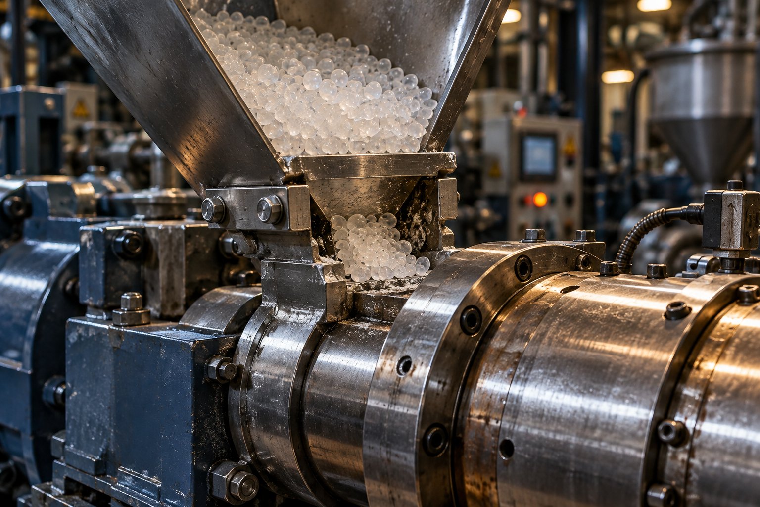
Your Extruder Feeding Instability Isn't Random — Here's Why
Oct 22, 2026
Extruder feeding instability causes surging output and scrap. Learn the 6 root causes, polymer-specific fixes, wear diagnostics, and preventive protocols.
Read Article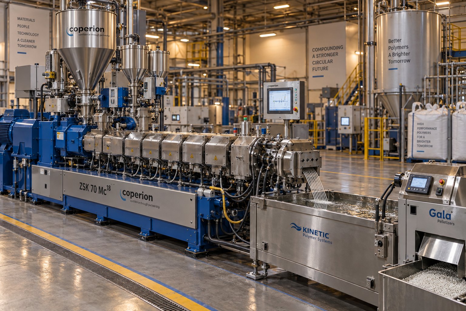
Parallel Twin Screw Extruder for Compounding Demystified: Lab to Line
Oct 21, 2026
Learn how a parallel twin screw extruder for compounding works—from screw element design and zone configuration to lab-to-production scale-up and process optimization.
Read Article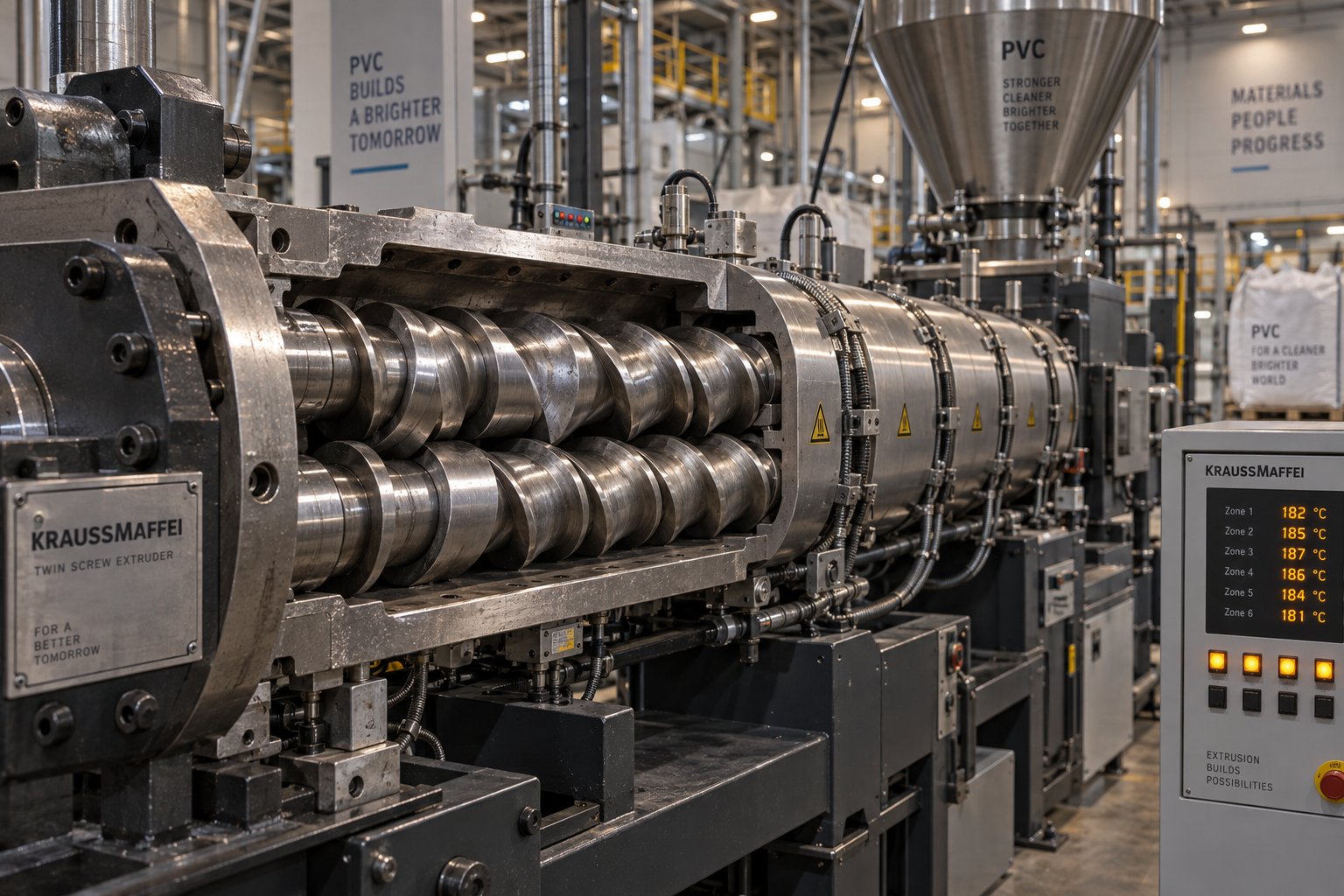
Twin Screw Extruder for PVC: The Setup Mistake Draining Profit
Oct 21, 2026
Learn how to match twin screw extruder configurations to PVC applications. Covers conical vs parallel, counter-rotating vs co-rotating, wear management, and troubleshooting.
Read ArticleLooking for something else?
Search by material, symptom or product and jump straight to the relevant page.
These are navigation suggestions based on keyword matching — not a quotation, not a delivery commitment, and not a substitute for engineering review. Final specification is confirmed by our engineers against your drawings and processed material.
Need help with screw barrel selection?
Share your machine model, processed material and application. Our team can help with pricing and technical support.