

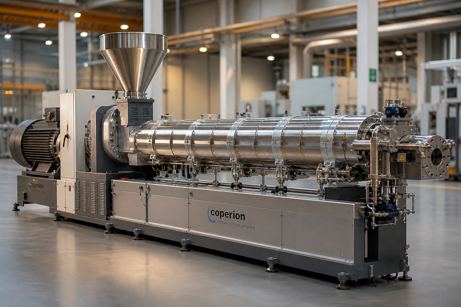
What Is Twin Screw Extrusion and Why Does It Matter
Imagine feeding raw plastic pellets, pharmaceutical powders, or food ingredients into one end of a machine and collecting a perfectly blended, precisely shaped product at the other. That is the core promise of twin screw extrusion - and it delivers on it millions of times a day across factories worldwide.
Defining Twin Screw Extrusion
Twin screw extrusion is a continuous manufacturing process in which two intermeshing screws rotate inside a heated, closed barrel to convey, melt, mix, and shape materials into a uniform product.
What separates a twin-screw extruder from a standard single screw system? The answer comes down to interscrew interaction. In a single screw setup, one rotating screw pushes material forward through drag flow alone. A twin screw design, by contrast, uses two screws that intermesh like gears, creating multiple high-shear zones between the screw flights, barrel walls, and the screws themselves. A historical review published in AAPS PharmSciTech identifies five distinct shear regions within any twin screw cross-section - each contributing to far more thorough distributive and dispersive mixing than a single screw can achieve.
This extrusion extruder architecture means materials are separated into small, bounded melt pools and subjected to repeated division, recombination, and directional flow changes. The result is a homogeneous output with tighter quality tolerances, even when processing complex multi-component formulations.
Why Twin Screw Technology Dominates Modern Processing
The technology's roots stretch back roughly a century, when early twinscrew designs emerged for natural rubber and food applications. Through the mid-1900s, batch mixers and single screw machines handled most polymer processing. A tipping point arrived in the 1970s and 1980s: modular barrel segments replaced one-piece steel housings, segmented screw elements on splined shafts replaced fixed screw designs, and screw speeds climbed from under 50 rpm to well over 1,000 rpm. By the 1990s, the twin screw had become the preferred continuous mixer for compounding across the plastics industry, effectively ending early attempts to use single screw extruders for intensive mixing tasks.
Modern systems build on that legacy with cartridge-heated modular barrels, internal liquid cooling bores, asymmetrical splined shafts for maximum torque, and PLC-based controls with full data logging. The twinscrew platform today is, as industry veterans describe it, a "battle-hardened" manufacturing workhorse validated in 24/7 industrial environments for over half a century.
Who Benefits From Understanding This Process
Twin screw technology touches a remarkably broad range of industries:
- Plastics engineers rely on it for compounding color masterbatch, mineral-filled compounds, and glass-fiber-reinforced materials.
- Pharmaceutical scientists use it to create amorphous solid dispersions that improve the bioavailability of poorly soluble drugs.
- Food processors depend on it for snack texturization, cereal cooking, and protein structuring.
- Advanced materials researchers are pushing it into battery electrode slurry processing and biodegradable polymer development.
Whether you are selecting your first twin screw system, optimizing an existing line, or troubleshooting a production bottleneck, a deep understanding of how these machines work - from screw element geometry to process parameter interactions - directly translates into better products, less waste, and lower operating costs.
This article breaks the process apart piece by piece. It starts with a head-to-head comparison against single screw systems, moves through screw configurations and element design, tackles process optimization strategy, and closes with real-world troubleshooting guidance and barrel selection criteria. Each section is built to give you actionable knowledge, not surface-level summaries.
The first question most processors ask is straightforward: when does a twin screw actually outperform a single screw, and when is the added complexity unnecessary?
Twin Screw vs Single Screw Extrusion Compared
Choosing between a single screw extruder and a twin screw extruder is one of the most consequential equipment decisions a processor will make. The two platforms share a basic concept - rotating an extruder screw inside a heated barrel to convey and shape material - but they differ fundamentally in how they move, melt, and mix that material. Understanding where each machine excels prevents both overspending on unnecessary capability and underperforming with the wrong tool.
Fundamental Mechanical Differences
A single screw extruder relies on one rotating screw that pushes material forward primarily through drag flow - friction between the polymer, the screw flights, and the barrel wall. Feed rate and screw speed are directly coupled, meaning you cannot adjust one without affecting the other. This simplicity is an advantage for straightforward melting and pumping tasks, but it limits your control over mixing intensity.
A double screw extruder, by contrast, uses two screws whose flights intermesh within a figure-eight barrel bore. This intermeshing creates positive displacement conveying, which decouples feed rate from screw speed. You can "starve-feed" the machine - introducing material at a controlled rate independent of how fast the screws turn. That separation gives you an extra degree of freedom: screw speed controls shear and mixing energy, while a separate feeder controls throughput. It is this independence that makes the twin screw extruder so adaptable to diverse formulations and processing goals.
Mixing and Conveying Performance Compared
The table below provides a direct, parameter-by-parameter comparison across eight critical dimensions. You will notice that neither machine is universally superior - each has a clear performance envelope.
| Parameter | Single Screw Extruder | Twin Screw Extruder |
|---|---|---|
| Mixing Capability | Limited distributive mixing; poor dispersive mixing without static mixers | Excellent distributive and dispersive mixing via kneading blocks and modular screw elements |
| Throughput Flexibility | Feed rate coupled to screw speed; narrow operating window | Starve-fed operation decouples feed rate from screw speed; wide operating window |
| Self-Cleaning Ability | No self-wiping; material can stagnate in dead zones | Intermeshing co-rotating designs are fully self-wiping; fast color and material changeovers |
| Residence Time Distribution | Broad distribution; less consistent thermal history | Narrow, controllable distribution; ideal for heat-sensitive and reactive materials |
| Energy Consumption | Lower specific energy for simple melting and conveying tasks | Higher specific energy input, but more efficient conversion into mixing work |
| Capital Cost | Lower initial investment; simpler gearbox and drive | Higher upfront cost due to complex gearbox, dual shafts, and modular barrel system |
| Operational Complexity | Easier to operate and maintain; fewer process variables | Requires trained operators; more variables to optimize but greater process control |
| Application Suitability | Pipe, profile, film, and sheet extrusion with pre-compounded materials | Compounding, reactive extrusion, devolatilization, masterbatch, pharma, and recycling |
When to Choose Twin Screw Over Single Screw
A single screw extrusion system handles the job well when you are processing a pre-compounded resin into a final shape - think PE pipe, PVC profiles, or cast film. The material arrives already formulated, and the extruder's role is simply to melt, convey, and meter it through a die. In these cases, the lower cost and simpler operation of a single screw make it the practical choice.
The calculus shifts the moment your process demands intensive mixing, multiple additive streams, or volatile removal. If you need to incorporate 60% calcium carbonate into a polyolefin matrix, blend color pigments to a dispersion standard measured in microns, or devolatilize residual monomers under vacuum, a screw extruder with twin intermeshing screws becomes essential rather than optional. The modular screw design lets you arrange conveying elements, kneading blocks, and mixing elements in virtually any sequence, tailoring the shear profile zone by zone. That modularity, combined with starve-fed operation, transforms the machine from a simple pump into a configurable continuous reactor.
Screw extrusion technology, in short, is not a one-size-fits-all decision. It is a question of matching the machine's capabilities to the complexity of your formulation and the precision your end product demands. The performance gap widens further when you consider the different twin screw configurations available - co-rotating versus counter-rotating, parallel versus conical - each engineered for a distinct processing niche.
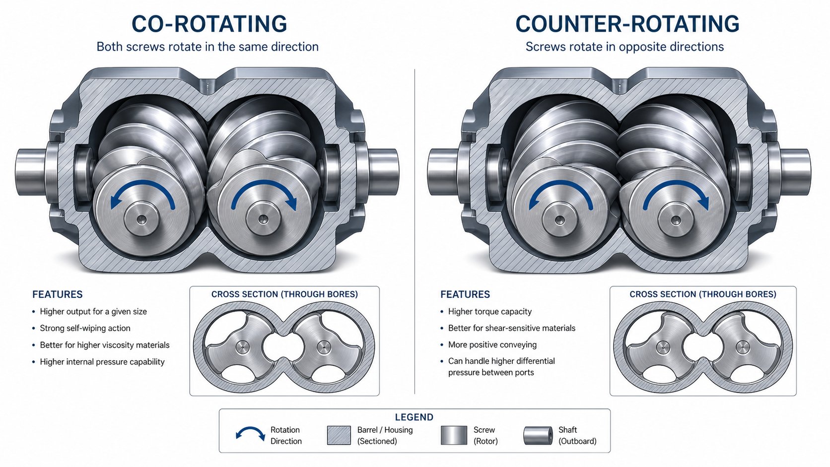
Co-Rotating vs Counter-Rotating Twin Screw Configurations
Not all twin screws behave the same way. Two screws spinning in the same direction create a fundamentally different flow pattern than two screws spinning in opposite directions - and that difference determines which materials you can process, how fast you can run, and how cleanly you can switch between products. Selecting the right configuration is arguably the single most important decision when specifying a twin screw extruder, because it locks in your machine's mixing character, shear profile, and application range from day one.
Four main configurations exist, defined by two variables: rotation direction (co-rotating or counter-rotating) and screw engagement (intermeshing or non-intermeshing). Each combination produces a distinct material flow behavior. Here is how they compare at a glance before we explore the details.
| Configuration | Mixing Capability | Throughput Range | Self-Wiping Ability | Shear Level | Typical Applications | Cost Considerations |
|---|---|---|---|---|---|---|
| Co-Rotating Intermeshing | Excellent dispersive and distributive mixing | Wide; scales from lab to 100+ ton/hr | Fully self-wiping | Moderate to high; adjustable via element selection | Polymer compounding, masterbatch, reactive extrusion, pharma HME, devolatilization | Higher capital cost; modular design offsets via flexibility |
| Counter-Rotating Intermeshing | Good distributive mixing; limited dispersive | Moderate; often lower speeds | Partially self-wiping | Low to moderate; gentler on material | PVC pipe and profile, shear-sensitive compounds, cable coatings | Moderate cost; simpler screw geometry |
| Co-Rotating Non-Intermeshing | Moderate; relies on back-mixing between screws | Narrow; limited positive conveying | None | Low | Controlled reactive extrusion, specialty blending | Lower cost; limited commercial availability |
| Counter-Rotating Non-Intermeshing | Low to moderate; relies on friction-based conveying | Narrow | None | Low | Gentle mixing, certain chemical processes | Lower cost; niche market |
Co-Rotating Intermeshing and the Self-Wiping Advantage
When both twin screws rotate in the same direction and their flights fully intermesh, something powerful happens: the crest of one screw continuously sweeps the root of the other. Imagine two gears turning together, where one gear constantly cleans material off the surface of its partner. This is the self-wiping mechanism, and it is the single feature most responsible for the co-rotating twin screw extruder's dominance in modern processing.
Why does self-wiping matter so much in practice? Consider four tangible benefits:
- Elimination of dead spots. Material cannot stagnate in corners or crevices because the intermeshing geometry continuously scrapes every barrel and screw surface. This prevents thermal degradation of heat-sensitive polymers and ensures every particle receives a uniform thermal history.
- Faster changeovers. When you switch from a black masterbatch to a white compound, residual material purges quickly because nothing clings to hidden surfaces. Changeover times measured in minutes rather than hours translate directly into higher equipment utilization.
- Narrow residence time distribution. Because material moves through the barrel in a well-defined plug-flow-like pattern rather than recirculating unpredictably, every granule spends roughly the same amount of time inside the machine. This consistency is critical for reactive extrusion, where reaction conversion depends on precise time-temperature exposure.
- Suitability for heat-sensitive materials. Pharmaceutical hot-melt extrusion and biodegradable polymer compounding both demand tight control over thermal exposure. The narrow residence time distribution of a co-rotating intermeshing design prevents localized overheating that would degrade active ingredients or trigger unwanted chain scission.
The material flow pattern in a co-rotating intermeshing system follows a characteristic figure-eight or "infinity" shape. Melt transfers from one screw to the other at the intermeshing zone, creating repeated splitting and recombination that delivers outstanding dispersive and distributive mixing efficiency. Combined with modular screw elements that can be rearranged on splined shafts, this configuration offers the widest processing window of any twin screw design. You can dial in everything from gentle blending at low screw speeds to aggressive kneading at over 1,200 rpm - all on the same machine, by swapping element sequences.
It is no surprise, then, that the co-rotating intermeshing layout dominates compounding, masterbatch production, devolatilization, and most high-throughput industrial applications. Its combination of mixing intensity, throughput scalability, and process flexibility makes it the default choice unless your application specifically demands something different.
Counter-Rotating Configurations and Their Niche Applications
So when does "something different" apply? Counter-rotating intermeshing twin screw extruders - where the two screws turn in opposite directions - create a distinct material handling behavior. Instead of the figure-eight flow, material is trapped in enclosed C-shaped chambers formed between the screw flights and the barrel wall. These chambers act almost like positive-displacement pumps, conveying material forward with very little back-mixing.
This design generates lower shear compared to its co-rotating counterpart, which is exactly the point. PVC processing is the classic example. PVC is notoriously shear- and heat-sensitive: excessive mechanical energy input causes rapid degradation, discoloration, and even hazardous hydrogen chloride gas release. A counter-rotating intermeshing extruder provides the gentle plasticization and strong conveying forces PVC demands, making it the preferred choice for PVC pipe, profile, sheet, and cable coating extrusion.
Counter-rotating designs also suit other shear-sensitive formulations - certain thermoset pre-blends, rigid sheet production, and applications where you need high compression without aggressive kneading. The trade-off is reduced mixing intensity and typically lower maximum screw speeds, which limits throughput compared to co-rotating systems.
Non-intermeshing configurations, whether co-rotating or counter-rotating, occupy a much smaller market share. Without the intermeshing engagement, these machines lose both the self-wiping benefit and positive conveying action. They rely on friction-based material transport and offer gentler, less controlled mixing. You will encounter them in specialty chemical processes and certain reactive extrusion scenarios where minimal shear is paramount, but they are uncommon in mainstream polymer processing.
Parallel vs Conical Barrel Geometry
Beyond rotation direction and intermeshing type, barrel geometry introduces another important distinction. A parallel twin screw extruder features two screws with a constant diameter along their entire length. This design is standard for co-rotating compounding machines, offering the longest possible processing length for a given barrel size and the easiest modularity - you simply add or remove barrel sections and rearrange elements to change the L/D ratio.
A conical twin screw extruder, by contrast, uses screws that taper from a larger diameter at the feed end to a smaller diameter at the discharge end. This geometry creates a natural compression ratio as material moves forward, generating pressure buildup without requiring aggressive screw elements. Conical designs are almost exclusively counter-rotating and have carved out a strong position in PVC pipe and profile markets, where their enhanced feeding capability handles bulky PVC dry-blend powders effectively. The larger feed-end diameter provides greater torque capacity and intake volume, while the smaller discharge end builds the melt pressure needed to push material through complex profile dies.
For high-viscosity or bulky materials, conical systems offer practical advantages. Some laboratory-scale conical extruders even incorporate recirculation chambers that simulate different L/D ratios, enabling R&D teams to test formulations with minimal material quantities before scaling to full production.
The choice between co-rotating and counter-rotating, parallel and conical, ultimately comes down to matching the machine's flow characteristics to your material's sensitivity and your process's mixing demands. A co-rotating parallel twin screw extruder gives you maximum flexibility and throughput for compounding tasks. A counter-rotating conical system gives you the gentle, high-pressure processing that PVC and similar shear-sensitive materials require.
Configuration, however, only defines the machine's potential. Unlocking that potential depends on what sits on the screw shafts - the individual elements whose geometry, stagger angle, and sequence along the barrel transform a general-purpose platform into a process-specific tool.
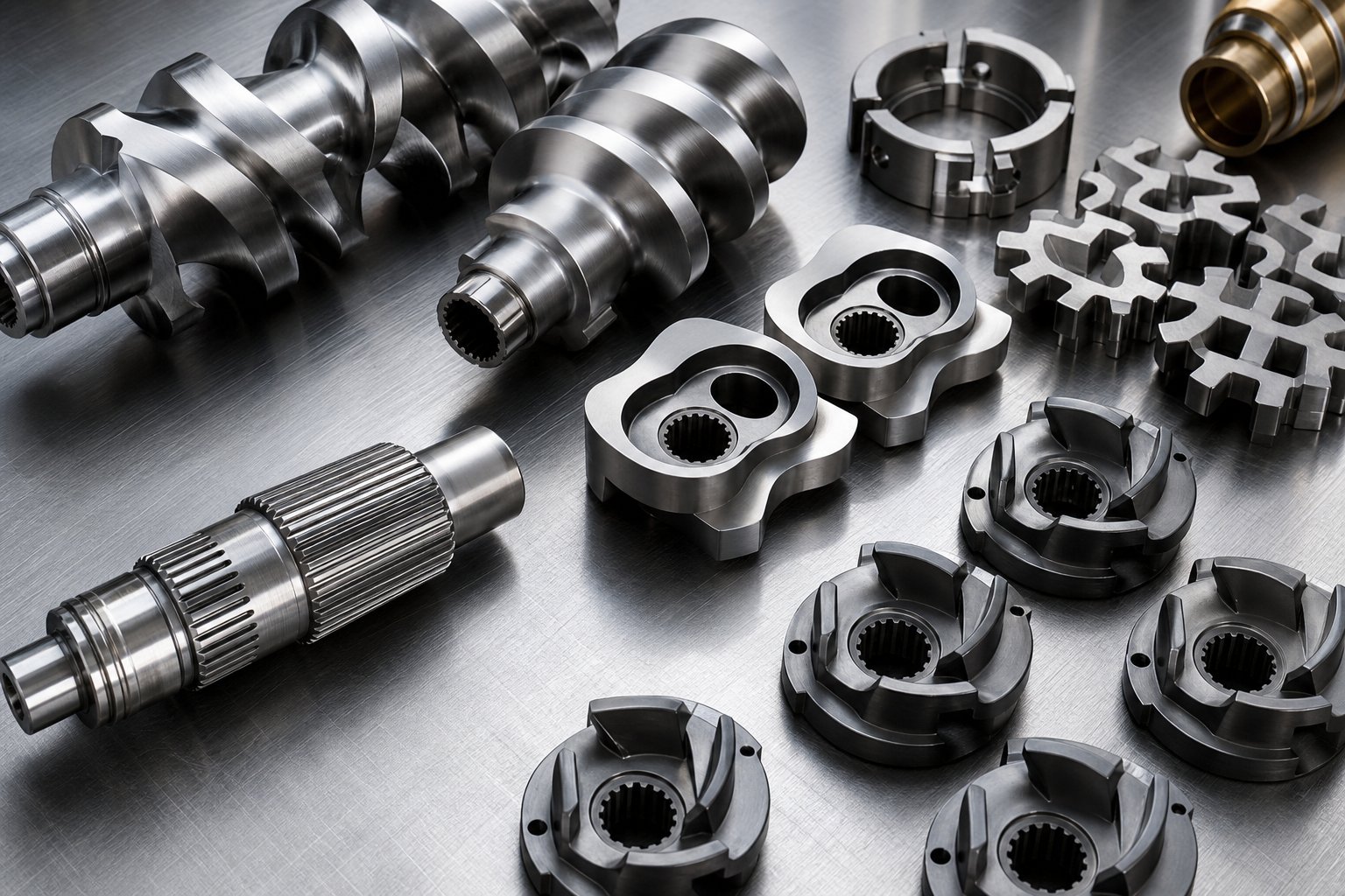
Screw Element Design and Modular Configuration
Picture a set of building blocks, each with a different shape and purpose, threaded onto a common shaft. That is exactly how a modern plastic extruder screw is constructed. Rather than machining a single, fixed-geometry screw from one steel blank, twin screw systems use individual elements - each a few centimeters long - that slide onto a splined shaft and lock together in a specific sequence. Change the sequence, and you change the machine's entire processing behavior without buying a new extruder.
This modular approach is what gives twin screw technology its extraordinary versatility. As an NC State Extension publication on screw profile design notes, configuring a screw is a blend of art and science - no single gold-standard profile exists because every material exhibits unique flow properties under varying shear, temperature, and geometric conditions. The splined shaft simply provides the mechanical backbone; the elements you choose and the order you place them in determine everything from melting efficiency to dispersion quality.
Modular Screw Construction and Element Types
Every element on the shaft serves one of a few core functions: move material forward, hold it back, melt it, mix it, or build pressure. The genius of modular design is that you combine these functions in precise sequences to create distinct processing zones along the barrel length. Here are the main element categories you will work with:
- Forward conveying elements - These helical, flighted elements transport material downstream through the barrel. Their behavior depends heavily on pitch (lead) - the axial distance the material travels per screw revolution. High-lead (large pitch) elements convey quickly with low fill levels and minimal shear, making them ideal for the feed zone where you want bulk solids to move freely without bridging. Low-lead (small pitch) elements slow the flow, increase barrel fill, and build pressure - exactly what you need approaching the die or ahead of a venting zone.
- Reverse conveying elements - These are left-handed versions of forward elements, actively pumping material backward against the main flow direction. They create a localized pressure dam that forces material to fully fill the barrel upstream. Reverse elements are essential for two purposes: forming melt seals ahead of vacuum venting ports (preventing air from being sucked upstream) and increasing residence time in mixing zones. Their length is typically kept shorter than the screw diameter to avoid excessive pressure peaks.
- Kneading blocks - The primary mixing workhorses of any twin screw profile. Each kneading block consists of a series of elliptical discs stacked at offset angles along the shaft. The disc width, number of discs, and stagger angle between them control whether the element performs dispersive mixing (breaking agglomerates into smaller particles) or distributive mixing (spreading ingredients uniformly throughout the matrix). Kneading blocks are covered in detail below.
- Toothed mixing elements (TME) - Instead of elliptical discs, these elements feature rows of protruding teeth that repeatedly divide and recombine the melt stream. They deliver excellent distributive mixing with relatively low shear, making them well suited for color dispersion, uniform additive distribution, and formulations where you want thorough blending without thermal degradation.
- Gear mixing elements (GME) and screw mixing elements (SME) - Specialized designs that generate elongational flow patterns rather than simple shear. Elongational flow stretches the melt, improving both distributive and dispersive performance in a single element. These are often chosen for engineering plastics, masterbatch production, and high-performance compounds where standard kneading blocks alone cannot achieve the required homogeneity.
- Dam elements and seal rings - Restrictive elements that force melt through a narrow annular gap, creating a sharp pressure drop. They serve as flow barriers ahead of venting zones, ensuring that the upstream section remains fully filled while the downstream vent section operates at reduced fill for effective volatile removal.
When engineers refer to an extruder screw and barrel system, they are really describing this entire assembly: the splined shaft loaded with a tailored sequence of elements, rotating inside a segmented barrel whose zones are independently heated and cooled. The barrel provides the thermal environment; the elements provide the mechanical processing action.
How Kneading Block Geometry Controls Mixing Intensity
Kneading blocks deserve special attention because they are the most frequently adjusted elements during screw profile optimization. Three geometric variables determine their behavior: disc width, stagger angle, and the number of discs per block.
Disc width directly controls shear intensity. Wide discs plow through the polymer, creating a pool of melt in front of each disc that gets smeared under high shear forces - a mechanism that promotes dispersive mixing. Narrow discs, by contrast, slice through the melt in a scissoring action, dividing and recombining the flow with minimal shear. This promotes distributive mixing - think of it as stirring rather than grinding. For the same total element length, narrower discs mean more discs and more frequent material exchanges between them.
Stagger angle governs how much forward conveying action the kneading block retains. Consider these common configurations:
- 30-degree stagger - Mild mixing with strong forward conveying. Material moves through quickly with gentle blending. Used where additives simply need to be folded into the melt.
- 45-degree stagger - Balanced mixing with moderate conveying. The most common general-purpose configuration, suitable for a wide range of compounding tasks.
- 60-degree stagger - Aggressive mixing with reduced forward movement. Material backs up, residence time increases, and shear forces intensify. Effective for breaking down stubborn agglomerates.
- 90-degree stagger (neutral) - Zero forward conveying from the element itself. Material only advances because upstream elements push it through. This creates the highest fill level and most intense mixing in the kneading zone.
- Negative (reverse) stagger - Actively pushes material backward, combining strong mixing with pressure generation. Used to seal venting zones or maximize dispersion in highly filled systems.
A practical rule of thumb emerges from these relationships: if your plastic extrusion screw profile needs to break down carbon black agglomerates or disperse nano-fillers, use wide discs with high stagger angles. If you are gently incorporating glass fibers or distributing a pre-dispersed colorant, use narrow discs with lower stagger angles to avoid fiber breakage and excessive melt temperature rise.
Sounds straightforward? The subtlety lies in combining these variables. A kneading section might start with 45-degree forward-conveying blocks for initial melting, transition to 60-degree blocks for intensive dispersion, and finish with a 90-degree neutral block or a short reverse element to ensure high fill and efficient mixing before material exits the zone. As veteran screw designer Kenneth Russell emphasizes, mixing sections work more efficiently and more gently when they have a higher degree of fill - but this must be balanced against excessive reverse flow that can overwork the material and spike melt temperatures.
Designing the Screw Profile for Specific Processing Goals
Individual elements only perform their intended function when placed in the right location along the barrel. A well-designed profile creates a series of functional processing zones, each built from a deliberate combination of element types:
- Feed zone - High-lead conveying elements with deep channels pull material away from the feed throat quickly, preventing bridging. In some formulations, think of a twin screw auger action here - the screws grab bulk solids or powders and move them downstream before any melting begins.
- Melting zone - Forward-conveying kneading blocks with progressively increasing stagger angles initiate plastication. Mechanical shear converts solid particles into a melt, with barrel heaters providing supplemental thermal energy.
- Mixing zone - The core of the profile for compounding applications. Combinations of kneading blocks, toothed mixing elements, and gear mixing elements deliver the dispersive and distributive mixing required by the formulation. A reverse element or neutral kneading block at the end of this zone ensures full fill for efficient mixing.
- Venting zone - High-lead conveying elements reduce fill level and increase exposed melt surface area, allowing moisture and volatiles to escape through atmospheric or vacuum vent ports. A melt seal (reverse element or dam) upstream prevents vent flooding.
- Pressure buildup zone - Low-lead conveying elements compress the melt and generate the pressure needed to push material through screen changers, diverter valves, and the die head. This is the final section before the extrudate exits the barrel.
The arrangement of these zones determines the product's melt quality, additive dispersion level, and the maximum throughput you can achieve before quality degrades. A plastic extruder screw profile designed for a 40% talc-filled polypropylene compound will look radically different from one designed for a pharmaceutical hot-melt extrusion of an amorphous solid dispersion - even on the same machine. The talc compound demands aggressive kneading with wide-disc, high-stagger-angle blocks to break mineral agglomerates, followed by robust venting to remove moisture. The pharma formulation needs gentler distributive mixing with narrow-disc kneading and toothed elements, plus a tightly controlled thermal profile to avoid degrading the active pharmaceutical ingredient.
This is why modularity matters so profoundly. A single twin screw platform, equipped with the right library of elements, can be reconfigured in hours to process entirely different materials. The screw profile is not a static design - it is a living process variable, refined iteratively as you develop formulations and optimize throughput.
Yet even a perfectly designed screw profile cannot compensate for incorrect process parameters. Screw speed, barrel temperature zones, feed rate, and their complex interactions ultimately control whether your carefully selected elements deliver the melt quality you designed them to produce.
Critical Process Parameters and Optimization Strategy
Screw elements define a machine's potential, but process parameters unlock it. Every experienced operator knows the feeling: a slight bump in screw speed sends melt temperature climbing, a small change in feed rate shifts the pressure profile, and an adjustment to barrel heating alters mixing behavior in ways that seem disproportionate to the input change. These interactions are not random. They follow a logic rooted in how energy enters the material - and understanding that logic is what separates systematic process development from expensive trial-and-error.
The twin screw extrusion process is governed by two categories of variables, a framework that Technovel describes as structural variables (hardware-side conditions fixed by machine specification) and operational variables (software-side conditions adjustable during running). Both categories interact continuously, and the resulting process behavior - melt temperature, pressure stability, mixing quality - reflects their combined effect.
Key Process Variables and How They Interact
Five critical variables shape the output of any twin screw extruder system. Here is how each one works and why none of them operates in isolation:
- L/D ratio. The length-to-diameter ratio sets the effective processing length available for melting, mixing, venting, and pressure buildup. A longer L/D (commonly 40:1 to 52:1 for compounding) gives you more barrel zones to work with - more room for kneading sections, multiple vent ports, and side feeding. A shorter L/D (25:1 to 32:1) limits residence time, which can be advantageous for heat-sensitive formulations but restricts the number of functional zones you can fit into the profile.
- Screw speed (rpm). This is the operational variable with the strongest direct effect on melt temperature. Higher screw speed raises the shear rate experienced by the material, which increases viscous dissipation - the conversion of mechanical energy into heat within the polymer itself. Experimental data from Technovel's ULTnano15 confirm that even when throughput and barrel temperature remain constant, increasing screw speed alone raises melt temperature while simultaneously lowering die pressure as reduced viscosity decreases flow resistance.
- Feed rate (kg/h). In starve-fed operation - the standard mode for co-rotating twin screw extruders - material enters the barrel at a rate controlled by an external feeder, not by the screw speed itself. Feed rate determines the fill level inside the screw channels. A higher fill ratio increases both shear stress acting on the material and the pressure gradient along the barrel. It also raises the mechanical energy delivered per unit time. However, overfilling the screws risks torque overload and unstable output.
- Barrel temperature profile (°C). Barrel heaters and cooling channels provide external thermal energy, which is particularly important in the early conveying zone where initial melting begins. Barrel temperature profiling - setting different temperatures across sequential barrel zones - lets you control where melting starts, how quickly it progresses, and whether the melt cools before exiting the die. At smaller equipment scales, barrel temperature has a pronounced effect on product temperature. At larger scales, this influence diminishes because the surface-area-to-volume ratio drops, and conduction from the barrel wall simply cannot penetrate the melt as effectively.
- Q/N ratio (throughput-to-screw-speed ratio). This parameter captures the interaction between feed rate and screw speed in a single number. At a constant Q/N, scaling both throughput and screw speed proportionally maintains a similar fill state - but melt temperature still rises because absolute shear rates increase. Adjusting Q/N up or down shifts the balance between fill-dominated behavior (high Q/N, higher pressure) and shear-dominated behavior (low Q/N, higher temperature rise).
Balancing Mechanical and Thermal Energy Input
Every polymer granule passing through the barrel absorbs energy from two sources simultaneously. Mechanical energy arrives via screw rotation - shear stress between flights and barrel walls, elongational flow through kneading blocks, and friction within partially filled channels. Thermal energy arrives through barrel heater conduction and, in some cases, die heating. The total energy input determines the material's final melt temperature, degree of mixing, and risk of degradation.
What makes this balance tricky is that the two energy sources do not contribute equally across the barrel length. In the early feed zone, thermal energy from barrel heaters dominates because the material is still solid and screw shear cannot generate much viscous dissipation. In the kneading zones, the situation reverses: mechanical energy input from the rotating screws overwhelms barrel heating, and shear-induced temperature rise can exceed the barrel setpoint by 20-40°C depending on screw speed and element aggressiveness.
Melt temperature and melt pressure are not determined by a single operational variable. They are formed by the combination of screw speed and throughput - that is, by the interaction between the fill state and the energy input state.
This insight, drawn from controlled experiments on a lab extruder, explains why adjusting one parameter in isolation rarely produces predictable results. The key evaluation metric that ties everything together is specific mechanical energy (SME) - the mechanical energy delivered per kilogram of material processed, expressed in kWh/kg. SME captures what temperature and pressure measurements alone can miss: the actual mechanical work history the material experienced inside the extruder.
A detailed case study published by Plastics Technology illustrates SME's practical importance. A masterbatch developed on a 26-mm lab scale twin screw extruder at an SME of 0.083 kWh/kg was scaled to a 40-mm pilot machine. Directly transferring the optimized conditions produced severe pressure fluctuations and phase separation - the SME had dropped to just 0.055 kWh/kg. Only after adjusting screw design, temperature profile, and screw speed to restore SME to 0.079 kWh/kg did the process stabilize. Scaling further to a 92-mm production extruder repeated the pattern: initial SME plummeted to 0.026 kWh/kg, producing unmelted pellets at the discharge. Redesigning the screw and feed configuration brought SME back to 0.086 kWh/kg, restoring full melt homogeneity and enabling the target production rate.
The lesson is clear. SME serves as a scale-independent fingerprint of the extruder for polymer processing. Matching it across equipment sizes - from a laboratory scale extruder used in early development through pilot and production machines - is one of the most reliable strategies for preserving product quality during scaleup.
A Systematic Approach to Process Optimization
Approaching process development methodically rather than chasing problems one variable at a time saves weeks of production trials and kilograms of wasted material. The following sequence reflects best practices drawn from both polymer compounding and pharmaceutical melt extrusion development:
- Define quality targets first. Identify the critical quality attributes your product must meet - dispersion level, residual volatile content, melt flow index, degradation limits, or dissolution performance. These targets become your success criteria, not machine settings.
- Select L/D ratio and screw configuration based on unit operations. Map out the functional zones your process requires (feeding, melting, mixing, venting, pressure buildup) and choose an L/D that accommodates them. Design the initial screw profile using element selection principles matched to your material's sensitivity and mixing demands.
- Establish a baseline barrel temperature profile. Set zone temperatures based on the material's melting point, glass transition temperature, and degradation onset. Use a gradual ramp in the melting zone and hold or slightly reduce temperatures in downstream mixing zones to prevent overshoot.
- Set a moderate initial screw speed and feed rate. Start at a conservative Q/N ratio - typically mid-range for your machine size. This gives you a stable baseline from which to explore the effects of individual variable changes without risking torque overload or material degradation.
- Measure scale-independent process responses. Record melt temperature, die pressure, torque (as a percentage of maximum), and calculate SME. If residence time distribution matters for your formulation, characterize it early. These responses - not the input settings themselves - are the true indicators of process state.
- Adjust one variable at a time and track its effect on process responses. Increase screw speed while holding feed rate constant to observe shear-driven temperature rise. Then increase feed rate at constant screw speed to observe fill-driven pressure and torque changes. Build a mental (or documented) map of how each input moves each response.
- Optimize toward quality targets using process response correlations. Once you understand which responses correlate with your critical quality attributes, adjust inputs to hit those response targets. This approach, rooted in Quality by Design principles, creates a control strategy that transfers across equipment scales and even across different machine brands.
- Document the optimized process window. Record not just the final settings but the acceptable ranges for each variable that still produce on-spec product. This operating window becomes your reference for scaleup, troubleshooting, and future formulation adjustments.
| Process Variable | Primary Effect | Interaction to Watch |
|---|---|---|
| Screw Speed (rpm) | Increases shear rate, raises melt temperature, reduces melt viscosity | At constant feed rate, higher speed lowers die pressure as viscosity drops |
| Feed Rate (kg/h) | Increases fill ratio, raises shear stress and pressure gradient | At constant screw speed, higher feed raises both melt temperature and die pressure |
| Barrel Temperature (°C) | Controls external thermal energy input, affects melting onset and melt cooling | Influence weakens at larger scales; mechanical energy dominates in kneading zones |
| L/D Ratio | Sets available processing length, number of functional zones, and residence time | Longer L/D allows more mixing but increases total thermal exposure |
| Q/N Ratio | Balances fill state against shear intensity | Same Q/N at different absolute speeds still produces different melt temperatures |
| SME (kWh/kg) | Quantifies total mechanical energy delivered per unit mass | Best single indicator for scaleup; match SME across equipment sizes to preserve quality |
This systematic workflow transforms process development from a guessing game into an engineering discipline. It also reveals why early-stage work on a lab scale twin screw extruder is so valuable: the optimized SME, residence time characteristics, and quality-response correlations established on small equipment carry forward as reliable references when scaling to pilot and production machines.
With the right parameter strategy in place, the question shifts from "how do I optimize this process?" to "where do I actually apply it?" The range of industries and applications where twin screw extrusion delivers unique advantages is broader than most processors realize - and each application imposes its own distinct processing challenges.
Industrial Applications Where Twin Screw Extrusion Excels
Every application on this list exists because a single processing challenge demanded something a simpler machine could not deliver - whether that was breaking apart stubborn pigment agglomerates, stripping residual solvents under vacuum, or dispersing an insoluble drug into a polymer carrier at the molecular level. The twin screw compounding extruder did not become an industry standard by being a generalist. It earned its place by solving specific, high-stakes problems better than any alternative.
Polymer Compounding and Masterbatch Production
Polymer compounding is the heartland of twin screw technology. The fundamental challenge here is intimate mixing: you need to uniformly distribute additives, fillers, or colorants throughout a polymer matrix at concentrations that can range from a fraction of a percent to over 80% by weight. A compounding extruder handles this by combining precisely sequenced kneading blocks and mixing elements with starve-fed operation, giving you independent control over mixing intensity and throughput.
- Color and additive masterbatch. Pigment particles arrive as tightly bound agglomerates that must be broken down to primary particle size - often below 1 micron - and then distributed uniformly throughout the carrier resin. The compounding twin screw extruder achieves this through high-shear kneading zones operating at shear rates of 500-1,500 s⁻¹, followed by distributive mixing elements that spread the dispersed pigment evenly. Multi-stage vacuum venting in the rear barrel sections removes low-molecular-weight volatiles, preventing bubble defects in finished pellets. The self-wiping screw geometry also enables rapid color changeovers - a critical productivity factor when a single production line manufactures dozens of different colors per week.
- Mineral-filled compounds. Calcium carbonate, talc, and barium sulfate loadings of 40-80% demand aggressive dispersive mixing to break filler clusters while maintaining enough polymer coating on each particle to preserve mechanical properties. Side feeders introduce the mineral downstream of the melting zone, preventing excessive wear on feed-section elements and allowing the polymer to fully melt before absorbing high filler concentrations.
- Glass fiber reinforcement. The challenge with glass fibers is the opposite of minerals: you need to distribute them uniformly without destroying their length. Fiber breakage directly reduces the composite's impact strength and stiffness. Processors address this by feeding chopped glass fibers through a downstream side stuffer into an already-molten polymer stream, using gentle distributive elements rather than aggressive kneading blocks in the fiber incorporation zone.
Recycling and Pelletizing Applications
Plastics recycling places unique demands on the extruder that go well beyond simple remelting. Post-consumer and post-industrial scrap arrives contaminated with moisture, residual inks, adhesives, mixed polymer fractions, and degraded material. A twin screw plastic extruder tackles these challenges through a combination of features no single screw system can match:
- Contamination tolerance. Modular barrel segments with hardened liners resist abrasive wear from contaminants like sand, glass fragments, and metal particles commonly found in recycled streams. The self-wiping action prevents degraded material from accumulating in dead zones, which would otherwise cause black specks and gels in the output.
- Degassing and devolatilization. Multiple atmospheric and vacuum vent ports along the barrel length strip moisture, residual monomers, and volatile degradation products from the melt. This is essential for recycled PET, nylon, and polycarbonate, where even small amounts of residual moisture cause hydrolytic chain scission during processing.
- Upcycling through reactive extrusion. By introducing chain extenders, compatibilizers, or coupling agents through liquid injection ports, processors can rebuild molecular weight and improve the mechanical properties of degraded recyclate. The twin screw's narrow residence time distribution ensures these reactive additives contact every polymer chain for a consistent duration, preventing both under-reaction and over-reaction.
Pelletizing - the step immediately downstream of the extruder - also benefits from application-specific thinking. A screw extruder granulator system can be configured in three main ways, each suited to different materials and production scales:
- Strand pelletizing. Melt strands exit a multi-hole die, travel through a water cooling bath, and enter a strand cutter. This is the simplest and lowest-cost option, well suited for general compounding and recycling lines where pellet geometry tolerances are moderate.
- Underwater pelletizing. The melt is cut directly at the die face by rotating blades submerged in a water chamber. Pellets solidify almost instantly into uniform, spherical shapes with minimal dust and very consistent bulk density. This method excels for high-throughput lines, sticky materials like hot-melt adhesives, and formulations requiring tight pellet weight control.
- Water-ring pelletizing. A hybrid approach where a ring of water surrounds the die face but does not submerge it. The cutter operates in air at the die face, and the water ring quenches pellets immediately after cutting. This balances the pellet quality advantages of underwater systems with the simpler startup and lower cost of strand systems.
Emerging Applications in Pharma and Energy Storage
The pharmaceutical industry's adoption of twin screw technology represents one of the most significant cross-industry technology transfers of the past two decades. The specific challenge: many new drug compounds have poor aqueous solubility, meaning patients absorb only a fraction of the active ingredient from conventional tablet formulations. A hot melt extruder solves this by molecularly dispersing the drug within a polymeric carrier to create an amorphous solid dispersion (ASD).
A study published in AAPS PharmSciTech demonstrated this approach with a BCS Class II compound whose bioavailability from an ASD produced by hot melt extrusion was four times higher than a crystalline tablet formulation. The twin screw platform enabled systematic scale-up from a 9-mm mini-extruder (5-20 g batches) through a 16-mm lab system to an 18-mm clinical-scale machine using specific energy as the scale-independent transfer parameter. This continuous manufacturing approach - where raw powders enter one end and a finished dispersion exits the other - eliminates the solvent handling, spray drying, and multi-step drying operations that traditional pharmaceutical processes require.
Food and feed processing relies on the twin screw for similar reasons: precise control over shear, temperature, and residence time in a continuous flow. Applications include:
- Snack and cereal texturization - where the extruder simultaneously cooks, shapes, and expands starch-based doughs.
- Pet food and aquafeed production - where high protein content and fat injection demand intensive mixing without burning or denaturing sensitive ingredients.
- Plant-based protein structuring - where the screw profile creates fibrous, meat-like textures from soy or pea protein isolates through controlled thermomechanical processing.
Two emerging frontiers are expanding the twin screw's reach into entirely new sectors. Battery electrode manufacturing uses twin screw extruders to prepare electrode slurries by mixing active materials like lithium compounds with binders and conductive additives into a homogeneous paste. The latest dry electrode processing techniques use the extruder to fibrillate binder materials without solvents at all, dramatically reducing energy consumption and eliminating toxic solvent recovery steps from battery cell production. Meanwhile, biodegradable polymer compounding - blending PLA, PHA, or starch-based resins with plasticizers, nucleating agents, and natural fibers - demands the precise thermal control and narrow residence time distribution that prevent premature degradation of these inherently sensitive biopolymers.
Across every one of these applications, the extruder itself is only the centerpiece. Consistent output quality depends on what happens upstream - how materials are fed, dosed, and introduced - and downstream - how the melt is filtered, shaped, cooled, and cut. Building a complete extrusion line means integrating every component into a coherent system, and that system-level thinking is where many processors find the biggest performance gains.
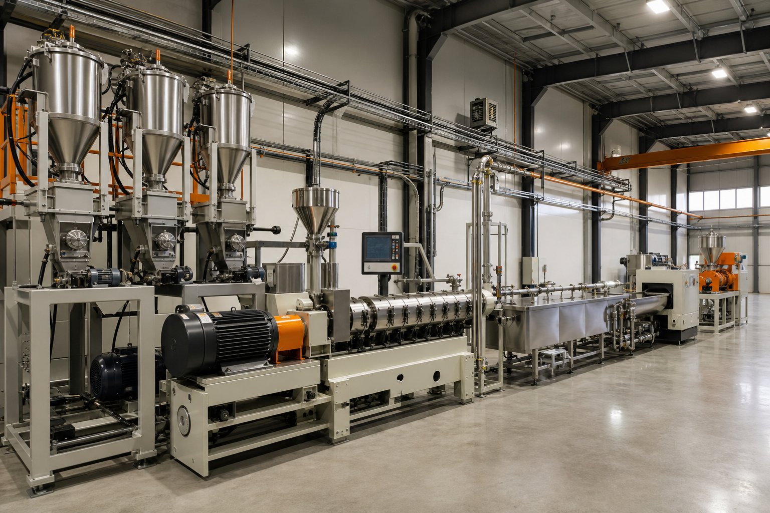
Building the Complete Twin Screw Extrusion Line
A twin screw extruder machine sitting alone on a factory floor produces nothing. It needs material in the right form, at the right rate, entering the right barrel zone - and it needs downstream equipment that converts the melt stream into a finished, packaged product. The extruder is the heart of the line, but every upstream feeder and every downstream pelletizer must work in concert with it. When one component falls out of sync - a feeder starving the screws, a plugged vent port, a screen changer triggering pressure spikes - the entire line suffers, regardless of how perfectly optimized your screw profile and process parameters are.
Think of it this way: you would not tune a race engine and then bolt it to a broken transmission. The same logic applies here. Building a twin-screw extruder machine line means integrating every piece of auxiliary equipment into one coherent system. Here is how each major component contributes.
Feeding Systems and Material Introduction Methods
Because co-rotating twin screw extruders operate in starve-fed mode, the feeding system - not the screw speed - controls throughput. That makes feeder accuracy one of the most consequential variables in your entire process. Two primary feeder types serve the main resin stream, and the choice between them shapes both product consistency and operating cost.
- Gravimetric feeders measure material by weight in real time, using a load cell mounted beneath the hopper to track mass loss per unit time. When bulk density fluctuates - as it does with regrind, recycled flake, or powder blends - the feeder dynamically adjusts screw speed or vibratory amplitude to maintain a constant mass flow. This precision is essential for high-performance compounding, pharmaceutical extrusion, and any application where additive concentrations must stay within tight tolerances.
- Volumetric feeders dispense material based on volume, relying on a consistent bulk density assumption. They are simpler, less expensive, and perfectly adequate when you are processing a single resin with stable pellet geometry and minimal lot-to-lot density variation. However, if bulk density shifts - from pellets to powder, from virgin to regrind - a volumetric feeder cannot compensate, and your actual mass throughput drifts without warning.
Beyond the main feed, most compounding lines incorporate additional material introduction points along the barrel:
- Side feeders (side stuffers). These are small twin screw units mounted to a barrel port downstream of the melting zone. They force fillers like calcium carbonate, talc, or chopped glass fibers directly into an already-molten polymer stream. Downstream introduction protects the main feed-section elements from abrasive wear and prevents filler from interfering with initial melting. For glass-fiber-reinforced compounds, side feeding is not optional - it is the only way to preserve fiber length during incorporation.
- Liquid injection systems. Oils, silane coupling agents, peroxides for reactive extrusion, and plasticizers are introduced through injection ports using precision metering pumps. Placement matters: coupling agents typically enter near or just upstream of the filler addition point so they contact fresh mineral surfaces immediately. Peroxides for controlled-rheology polypropylene enter the melt zone where temperature is high enough to trigger decomposition but residence time is long enough for complete reaction.
Each feed point requires careful coordination. A gravimetric loss-in-weight feeder on the main hopper, a second gravimetric feeder on the side stuffer, and a calibrated metering pump for liquids must all communicate with the line's central PLC to maintain the correct ratio as total throughput ramps up or down. Even small mismatches accumulate into measurable composition drift over a production shift.
Venting and Devolatilization Zones
Moisture in polymer pellets, residual monomers in recycled streams, and reaction byproducts from reactive extrusion all need an exit path. That is what venting zones provide - strategically placed openings in the barrel where volatiles escape from the melt surface into the atmosphere or a vacuum system.
Two types of venting serve different purposes:
- Atmospheric vents. Open barrel ports positioned upstream in the conveying or early melting zone, primarily for removing surface moisture and entrained air from incoming pellets or powder. These are simple, low-cost, and effective for materials with moderate moisture content.
- Vacuum vents. Barrel ports connected to a vacuum pump, typically placed in the downstream half of the barrel where the material is fully molten. Vacuum reduces the partial pressure of volatiles above the melt surface, dramatically increasing the driving force for mass transfer. This is critical for stripping residual monomers from recycled PET, removing solvents from reactive extrusion, or meeting the strict residual volatile limits required for food-contact and pharmaceutical applications.
Effective venting depends on screw design as much as barrel hardware. The screw profile must create a low-fill, low-pressure zone directly beneath the vent port so that volatiles can escape without the melt itself being pushed out through the opening. Upstream of each vent, a melt seal - typically a short reverse element or a neutral kneading block - builds a pressure barrier that keeps the fully filled upstream section from flooding forward into the vent zone.
Vent flooding is one of the most common and frustrating problems on any double screw extruder machine line. It happens when the fill level in the vent zone rises too high, pushing melt into the vent opening where it solidifies, blocks the port, and eventually contaminates the vacuum system. The usual causes are overfilling from excessive feed rates, insufficient melt seal length, or a screw speed too low to convey material away from the vent fast enough. Addressing it requires adjusting the balance between feed rate, screw speed, and the restrictive element design upstream of the vent - not simply widening the vent port.
Downstream Equipment and Pelletizing Options
Everything downstream of the die head converts a continuous melt stream into discrete, handleable pellets. Each component in this chain must match the extruder's output rate and the material's cooling characteristics.
- Screen changers. Positioned between the barrel exit and the die head, screen changers force the melt through wire mesh filters that trap gels, char particles, metal fragments, and unmelted material. The differential pressure across the screen pack - not elapsed time - should trigger screen changes for optimal filter utilization. Hydraulic double-piston continuous screen changers allow filter swaps without stopping production, a necessity on high-throughput recycling and compounding lines.
- Die heads. These shape the melt stream into strands, sheets, or directly into pellet-forming geometries. Die design must balance flow distribution uniformity across all die holes with manageable pressure drop. Poorly balanced dies produce strands of uneven diameter, leading to inconsistent pellet size and bulk density problems.
- Strand pelletizers. Melt strands travel through a water cooling bath, across an air knife or suction dryer, and into a rotating blade cutter. This is the simplest, most forgiving pelletizing method - easy to start, easy to troubleshoot, and well suited for a wide range of compounds.
- Underwater pelletizers. Rotating blades cut the melt directly at the die face inside a pressurized water chamber. Pellets solidify within milliseconds into uniform, nearly spherical shapes with excellent bulk density consistency. Underwater systems excel at high throughput rates, sticky formulations, and applications requiring very tight pellet weight tolerances.
- Water-ring pelletizers. A compromise between strand and underwater systems: the cutter operates at the die face in air, while a surrounding water ring immediately quenches the freshly cut pellets. They offer better pellet shape than strand cutting with simpler startup procedures than full underwater systems.
- Cooling conveyors and classification systems. After pelletizing, pellets pass through vibrating screens or air classifiers that remove fines, oversized pieces, and agglomerated clusters. Cooling conveyors - either vibratory with air cooling or immersion water baths - bring pellet temperature down to safe storage and packaging levels.
Every component listed above must be sized and timed to the extruder's output. An undersized screen changer creates a pressure bottleneck that destabilizes die flow. An undersized pelletizer produces inconsistent cuts and excessive fines. An oversized cooling system wastes floor space and energy. Line integration means matching throughput capacity, pressure ratings, and control response times from feeder to bagging station.
At the foundation of this entire system sits the barrel and screw selection. The barrel's metallurgy, bore tolerance, and cooling channel design dictate how effectively the screws perform every function described in this article - conveying, melting, mixing, venting, and pressure buildup. For processors running compounding, pelletizing, recycling, or masterbatch lines with abrasive or corrosive formulations, purpose-built barrel solutions make a measurable difference. Providers like NANHAIYA offer custom parallel twin screw barrels engineered specifically for high-wear applications in twin screw plastic extruder lines, addressing the demands of mineral-filled compounds, glass fiber reinforcement, and recycled feedstocks that accelerate barrel wear far beyond what standard components can withstand.
Barrel and screw quality are invisible when everything runs well - and glaringly obvious when something goes wrong. Worn barrels widen clearances, degrading mixing efficiency and allowing melt bypass. Damaged screw elements lose their self-wiping geometry, creating dead spots that generate black specks and degradation. Recognizing these failure patterns early, before they compromise product quality, is the subject of practical troubleshooting - and it is where experienced operators earn their value.
Troubleshooting Common Twin Screw Extrusion Problems
A perfectly optimized process can unravel in minutes. One shift everything runs smoothly - stable torque, consistent pellet quality, clean vent ports. The next shift, the torque alarm trips, die pressure swings wildly, or black specks appear in the product. If you have spent any time running twin screw extruders, you know these scenarios are not hypothetical. They are Tuesday.
What separates a quick recovery from hours of lost production is the ability to read the symptoms, trace them to root causes, and apply corrective actions in the right sequence. The troubleshooting table below covers the seven most common problems encountered on twin-screw extruders in compounding, recycling, and masterbatch operations. Refer to it as a diagnostic reference - each row connects visible symptoms to their underlying causes and specific fixes.
| Problem | Common Causes | Diagnostic Indicators | Corrective Actions |
|---|---|---|---|
| Torque Overload | Overfeeding beyond screw capacity; barrel temperatures too low in melting zone causing unmelted solids; screw design mismatch (too many restrictive elements for the formulation); high-viscosity material processed at excessive throughput | Torque reading at or above motor limit; frequent drive trips; motor housing running abnormally hot; elevated current draw on control panel | Reduce feed rate immediately to bring torque within 70-85% of rated maximum; raise barrel temperatures in zones 2-4 to promote earlier melting; reduce the number or aggressiveness of reverse elements and neutral kneading blocks; verify material viscosity matches the process recipe |
| Feed Bridging / Inconsistent Feeding | Moisture-induced clumping in the hopper; irregular particle size or fibrous additives interlocking above the feed throat; feed throat overheating causing premature melting and material sticking; worn or improperly calibrated feeder screws | Fluctuating feed rate readings on the gravimetric controller; erratic torque and die pressure swings with a periodic pattern; visible material arching or ratholing in the hopper | Verify feed throat cooling is maintaining 20-40°C; install hopper agitators or vibratory devices; pre-dry hygroscopic materials to below 0.05% moisture; recalibrate feeder using the actual production material, not a substitute; match feeder screw geometry to material bulk density |
| Output Surging / Pressure Instability | Inconsistent screw fill from feeder fluctuations; partially blocked screen pack raising and releasing pressure intermittently; worn conveying elements in the metering zone reducing pumping stability; incorrect Q/N ratio | Die pressure oscillations exceeding ±5% of setpoint; visible strand diameter variation at the die face; pellet weight inconsistency detected by downstream QC | Check and recalibrate the feeder; inspect screen pack for partial blockage and replace if differential pressure exceeds limits; measure conveying element wear and replace elements beyond tolerance; adjust Q/N ratio to stabilize fill level in the pressure buildup zone |
| Material Degradation | Excessive residence time from overly restrictive screw profile; melt temperature exceeding polymer stability limits due to high screw speed or aggressive kneading elements; dead spots from worn self-wiping geometry; insufficient cooling in downstream barrel zones | Discoloration or yellowing of extrudate; reduced mechanical properties in finished product; elevated melt temperature readings at the die; off-gassing or odor at the die exit; gels and black specks in pellets | Reduce screw speed to lower shear-induced temperature rise; replace aggressive wide-disc kneading blocks with narrower-disc elements; shorten or remove unnecessary reverse elements to reduce residence time; increase barrel cooling in zones where melt temperature overshoots setpoint; inspect screws for worn flight tips that create stagnant pockets |
| Vent Flooding | Fill level too high in the vent zone from excessive feed rate; insufficient melt seal length upstream of the vent port; screw speed too low to convey melt away from the vent section; high melt viscosity preventing proper pressure relief | Melt visibly pushing into the vent opening; solidified polymer plugging the vent port or vacuum line; vacuum level dropping or fluctuating on the gauge; visible smoke or condensate backing up into the vent stack | Reduce feed rate to lower the fill level in the vent zone; extend the melt seal by adding a longer reverse element or an additional neutral kneading block upstream of the vent; increase screw speed slightly to improve conveying through the vent section; raise barrel temperature in the zone preceding the vent to reduce viscosity |
| Die Drool and Buildup | Low-molecular-weight polymer fractions, additives, or waxes migrating to the die lip; melt temperature too high causing surface degradation at the die exit; poor die lip finish or nicked edges creating nucleation sites for buildup | Gradual accumulation of degraded material around die holes; occasional drool deposits breaking off and contaminating strands or pellets; increasing frequency of required die face cleaning | Optimize the temperature profile in the final barrel zone and die to avoid overheating the melt surface; polish die lip surfaces to a mirror finish and remove any nicks or burrs; ensure vacuum venting upstream is effectively stripping volatiles and low-MW fractions before the melt reaches the die; schedule regular die cleaning intervals based on buildup rate rather than elapsed time |
| Abnormal Screw and Barrel Wear | Abrasive fillers (glass fiber, minerals, recycled contaminants) eroding flight tips and barrel liner; misaligned screw shafts causing metal-to-metal contact on one side; corrosive additives or acidic decomposition products attacking steel surfaces; operating above recommended torque limits | Declining output at constant screw speed and feed rate (reduced specific rate); increasing melt temperature at constant settings due to wider clearances reducing heat transfer; uneven wear patterns visible on removed screw elements - one-sided wear suggests misalignment, uniform tip wear suggests abrasion | Measure screw outer diameter at multiple points and compare to OEM specifications; replace elements when wear exceeds the manufacturer's tolerance (typically 0.2 mm beyond nominal clearance); check barrel bore with a telescoping gauge for ovality or localized wear pockets; verify shaft alignment and correct if gap variation exceeds 0.1 mm; upgrade to harder metallurgies (bimetallic liners, tungsten carbide coatings) for high-abrasion formulations |
Diagnosing Torque Overload and Feed Issues
Torque overload is the most urgent alarm on any twin screw extrusion line because it triggers an automatic shutdown, halting production instantly. The instinct is to restart and reduce speed, but the real question is why torque spiked in the first place. Overfeeding is the most frequent culprit - a feeder calibration drift, a sudden change in bulk density when switching material lots, or an operator manually increasing throughput without verifying that the motor can handle the load.
Temperature plays a subtler role. If the melting zone barrels are set too cold, polymer enters the kneading section as partially unmelted solids. These solid fragments create enormous resistance against the rotating screw elements, spiking torque even at modest feed rates. You will notice this as a torque increase that correlates with the time it takes material to travel from the feed throat to the first kneading block - typically 30 to 90 seconds after the temperature deviation begins.
Feed bridging, meanwhile, creates the opposite signal: torque drops because material stops reaching the screws. The telltale pattern is a periodic fluctuation - torque and die pressure cycling up and down as bridged material intermittently collapses and then re-arches. Checking the hopper visually during these cycles usually confirms the diagnosis. Feed throat cooling is the first thing to verify, as temperatures above 40°C in the feed throat zone cause premature softening that sticks material to the feed screw and inner walls, progressively restricting the flow opening.
Solving Output Instability and Material Degradation
Output surging and material degradation are two problems that often coexist - and solving one without addressing the other leads to frustration. Surging manifests as visible strand diameter variation at the die face or measurable pellet weight swings downstream. It stems from inconsistent fill in the metering section, which translates directly into fluctuating die pressure.
Before adjusting the extruder, check the screen changer. A partially blocked screen pack acts like a variable restriction valve: as contaminants accumulate, pressure rises; when a portion of the blockage breaks free, pressure drops suddenly. This creates surging that looks identical to a feeding problem but cannot be fixed by feeder adjustments. Monitoring the differential pressure across the screen - not just absolute die pressure - isolates this cause quickly.
Material degradation requires a different diagnostic approach. Discoloration, reduced mechanical properties, and gels all point to excessive thermal exposure, but the source could be shear-driven heat, excessive residence time, or stagnant melt in dead zones. Screw extruders operating at high rpm generate substantial viscous dissipation, and melt temperature at the die can exceed barrel setpoints by 20-40°C in aggressive kneading configurations. If you measure actual melt temperature with an immersion thermocouple (not just the barrel thermocouple) and find it significantly above your profile, the corrective path runs through screw speed reduction, kneading block moderation, or both.
Vent flooding and die drool, while less production-critical than torque trips, erode quality insidiously. Vent flooding contaminates vacuum systems and creates surface defects; die drool periodically deposits carbonized material onto strands. Both share a root cause connection to upstream process control - proper melt sealing, adequate volatile removal before the die, and controlled melt temperature at the exit.
Recognizing Wear Patterns That Signal Deeper Problems
Screw and barrel wear is inevitable, but the pattern of wear tells a story. Uniform abrasive wear across all flight tips - evenly distributed around the circumference - is normal for lines processing mineral fillers, glass fibers, or contaminated recycled feedstocks. It progresses predictably, and you can plan replacement schedules based on periodic diameter measurements. Industry guidelines from extrusion specialists like Timothy Womer suggest that when flight clearance reaches roughly four times its original new value, mixing efficiency degrades enough to warrant element replacement - though critical applications like medical compounds may demand replacement at just two times the original clearance.
One-sided wear tells a different story entirely. If screw elements show heavy wear on one side and minimal wear on the opposite side, the screws are misaligned. Misalignment forces the screw against the barrel wall in a specific radial direction, accelerating localized metal removal. Left uncorrected, this pattern escalates rapidly - the growing gap on the worn side reduces conveying efficiency, which increases fill on the tight side, which accelerates wear further. Barrel alignment should be checked whenever screws are removed for inspection, especially on long-barrel, high-L/D systems where thermal expansion can shift support points over time.
Corrosive wear creates a distinctly different surface appearance: pitting, roughening, and chemical discoloration rather than the smooth polishing typical of abrasive wear. Processing PVC, fluoropolymers, or formulations with acidic flame retardants generates corrosive decomposition byproducts that attack standard nitrided steel. If you observe pitting on screw roots and barrel walls, the corrective action is metallurgical - upgrading to corrosion-resistant alloys or applying protective coatings - rather than operational.
The practical takeaway across all these wear patterns is straightforward: pull screws on a regular schedule, measure them quantitatively rather than eyeballing, and record the data over time. Trending wear rates per operating hour, correlated with the materials processed, transforms reactive screw replacement into predictive maintenance. You will know months in advance when elements will reach their wear limits - and that foresight eliminates the unplanned shutdowns that cost far more than replacement parts ever will.
Of course, the best wear management strategy starts before the first screw revolution, with the right barrel metallurgy and component specifications matched to your specific application. Selecting those components thoughtfully - based on material abrasiveness, processing temperature, and corrosion risk - determines how long your line runs before these troubleshooting scenarios become relevant at all.
Selecting the Right Twin Screw Barrel and Components
Every troubleshooting scenario described in the previous section - torque overloads, degradation, abnormal wear, output instability - traces back, at least partially, to how well the twin screw and barrel match the demands of the material being processed. A barrel lined with standard nitrided steel will not survive a year of running 60% calcium carbonate-filled polypropylene. A screw element built from solid powder metallurgy alloy may shatter under a torque spike that a bimetallic core would absorb without damage. These are not hypothetical risks. They are predictable consequences of mismatched metallurgy - and they are entirely preventable with the right component selection upfront.
So how do you choose? The decision involves four interconnected criteria: barrel metallurgy and wear protection, bore geometry and tolerance, cooling channel design, and the quality standard of replacement parts. Each criterion narrows the field based on what your specific formulation demands from the barrel extruder system it runs through.
Barrel Metallurgy and Wear Protection Options
The inner surface of a twin screw barrel endures constant mechanical abrasion from rotating screw flights, chemical attack from corrosive polymer decomposition products, and thermal cycling from repeated heating and cooling. The metallurgy you specify for that surface determines how long the barrel performs within tolerance - and how quickly clearances widen to the point where mixing efficiency, conveying stability, and product quality start to degrade.
Three main metallurgical approaches dominate the market, each suited to a different tier of processing severity:
- Nitrided steel liners. A surface-hardening treatment applied to alloy steel, producing a hard case (typically 65-70 HRC) over a tough core. Nitrided barrels offer good baseline wear resistance at the lowest cost and are well suited for processing unfilled polymers, color concentrates with non-abrasive pigments, and low-filler-loading compounds. However, their wear layer is relatively thin - once the nitrided case is penetrated, the softer substrate beneath erodes rapidly.
- Bimetallic liners. A centrifugally cast wear-resistant alloy bonded metallurgically to the inside of a steel barrel body. The liner material - typically a nickel-, cobalt-, or iron-based alloy with embedded carbide particles - provides substantially deeper wear protection than nitriding alone. Bimetallic construction is the standard choice for moderately abrasive applications such as talc-filled compounds, recycled plastics with contaminants, and engineering thermoplastics with flame retardant additives.
- Tungsten carbide and PM-HIP (Hot Isostatic Pressed) alloy liners. The highest tier of wear protection. PM-HIP alloys distribute hard carbide particles uniformly throughout a tough matrix, delivering both extreme abrasion resistance and improved corrosion resistance compared to conventional tool steels. As ENTEK's metallurgy overview documents, the industry has shifted dramatically toward these advanced materials - from just 10% HIP alloy usage a decade ago to roughly 60% today - reflecting the increasingly aggressive formulations modern compounders process. Tungsten carbide coatings and PM-HIP liners are specified for the most demanding applications: high glass fiber loadings, mineral concentrations above 50%, and abrasive recycled streams containing sand, metal fragments, or glass contaminants.
Corrosion adds a second dimension to the metallurgy decision. Processing PVC, fluoropolymers, or halogenated flame retardants generates acidic byproducts that attack standard steel through chemical mechanisms entirely different from abrasion. High-chromium tool steels offer the best cost-effective defense against corrosive wear. Extreme cases - fluoropolymer monomers, for example - may demand exotic nickel-based alloys like Inconel or Hastelloy, though these sacrifice hardness (Rockwell C 35 or below) and are rarely justified outside severely corrosive environments.
A parallel consideration applies to screw elements. Modern best practice, reflected in ENTEK's manufacturing approach, favors bimetallic screw construction: a tough steel core that resists torque overloads surrounded by a hard, wear-resistant PM-HIP outer layer. Solid HIP screw elements, while offering superior surface hardness, are brittle and prone to catastrophic breakage when torque exceeds normal limits - exactly the scenario that occurs during an accidental overfeed or cold-start event.
Matching Barrel Specifications to Your Application
Metallurgy gets the most attention, but it is only one variable in the barrel selection equation. Bore geometry, surface finish, and thermal management design all influence process performance in ways that matter daily on the production floor.
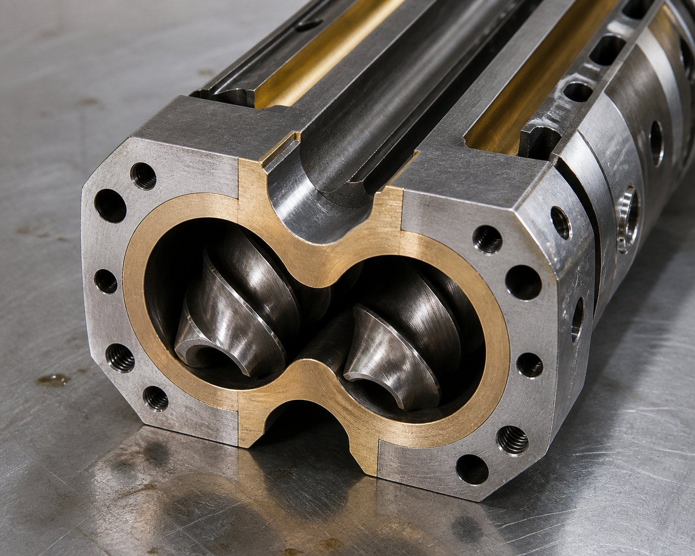
- Bore geometry and tolerance. The twin screw barrel bore is a figure-eight profile formed by two overlapping cylindrical bores, and the radial clearance between the screw flight tips and the barrel wall - the overflight gap - is typically 0.1 to 0.3 mm depending on machine size. This gap is where the highest shear rates in the entire barrel extruder occur, making it the primary site of dispersive mixing along the barrel wall. Bore diameter tolerance directly affects this clearance: too tight risks metal-to-metal contact during thermal expansion; too loose reduces shear intensity and allows melt bypass that degrades mixing quality. OEM-grade tolerances maintained within ±0.01 mm ensure consistent processing behavior across replacement barrel sets.
- Surface finish. In the feed zone, a rougher bore surface improves solids conveying by increasing friction between the polymer and the barrel wall. In downstream mixing and metering zones, a smoother finish reduces polymer adhesion, improves self-cleaning behavior, and minimizes material holdup that leads to degradation. Some barrel manufacturers offer zone-specific surface finish specifications to optimize both feeding and melt-phase performance.
- Cooling channel design. Internal cooling bores drilled or cast into the barrel body remove excess heat generated by viscous dissipation in kneading zones. The number, diameter, and routing pattern of these channels determine how quickly a barrel zone responds to cooling commands - a critical factor for heat-sensitive materials like PVC, biopolymers, and pharmaceutical formulations where a 5°C overshoot can trigger degradation. Multi-pass cooling channel designs with higher coolant flow rates provide faster thermal response than single-pass configurations, though they add manufacturing complexity and cost.
- Replaceable liner construction. Modern barrels are built almost exclusively with removable liners rather than monolithic construction. The upfront cost is higher because the liner-to-holder interface requires additional machined surfaces. The long-term savings, however, are substantial: when the liner wears beyond tolerance, you replace only the liner and reuse the barrel body - which contains all the cooling passages, thermocouple wells, injection ports, and mounting features. Over the life of a compounding line, this approach reduces barrel replacement costs by 40-60% compared to discarding entire barrel sections.
The barrel is not a passive container - it is an active processing component. Its metallurgy determines wear life, its bore tolerance controls mixing precision, and its thermal design governs temperature stability. Underspecifying any one of these directly increases scrap rates, maintenance costs, and unplanned downtime.
When evaluating twin screw extruder manufacturers or sourcing replacement components, do not treat barrel specifications as an afterthought. A machine's motor power, gearbox torque, and screw element library get the spotlight in sales presentations, but the barrel is the component that touches every gram of material you process. Its quality sets the ceiling on everything else.
Why Custom Barrel Solutions Reduce Total Cost of Ownership
Standard catalog barrels work well for general-purpose compounding with unfilled or lightly filled polymers. The economics change sharply once your formulations include aggressive fillers, corrosive additives, or the unpredictable contamination levels found in recycled feedstocks. In these scenarios, custom barrel solutions engineered for your specific processing demands deliver measurably lower total cost of ownership - even though the per-unit price is higher than off-the-shelf alternatives.
Consider what customization actually addresses:
- Wear-matched metallurgy. A barrel lined with the right alloy for your filler type and loading level lasts two to five times longer than a general-purpose liner in the same application. For a line running 24/7 with 50% glass-fiber-reinforced polyamide, extending barrel life from 4,000 to 12,000 operating hours eliminates two unplanned shutdowns per year - each costing tens of thousands of dollars in lost production, maintenance labor, and expedited replacement part shipping.
- Application-specific bore profiles. Custom bore geometry optimized for your Do/Di ratio and screw element clearances maintains tighter process control over the barrel's service life. As bore wear progresses, a barrel specified with tighter initial tolerances stays within acceptable processing limits longer than a loosely toleranced standard component.
- Thermal management tailored to your process. If your formulation demands aggressive cooling in specific zones - common in reactive extrusion, pharmaceutical hot-melt processing, and biodegradable polymer compounding - custom cooling channel layouts provide the thermal response that standard drilled-bore designs cannot match.
For processors seeking custom barrel solutions purpose-built for compounding, pelletizing, recycling, and masterbatch operations, NANHAIYA's parallel twin screw barrel solutions offer application-driven engineering for high-wear plastic processing. Their specialization in mixing, conveying, and granulation applications means barrel specifications are matched to the actual demands of mineral-filled compounds, glass-reinforced engineering plastics, and contaminated recycled streams - not designed around generic assumptions about what a barrel might encounter.
Whether you are sourcing your first twin screw extruder for sale evaluation, pricing replacement barrels for an existing line, or comparing twin screw extruder price quotations across suppliers, the barrel and screw metallurgy specification deserves the same scrutiny you give the motor, gearbox, and control system. A well-selected barrel is invisible during smooth production runs. A poorly selected one announces itself through accelerating wear, rising scrap rates, and maintenance invoices that erode the margins your process was designed to deliver.
The twin screw extrusion platform - from screw element design and process parameter optimization through line integration and troubleshooting - rewards processors who invest in understanding its details. Every section of this article has aimed to make those details accessible, practical, and immediately applicable. The machines will keep evolving. The formulations will keep getting more demanding. The processors who thrive will be the ones who match the right specifications to the right applications - and who treat their twin screw and barrel not as commodity parts, but as precision tools engineered for a specific job.
Twin Screw Extrusion: Frequently Asked Questions
1. What is the difference between twin screw and single screw extrusion?
Twin screw extrusion uses two intermeshing screws that create positive displacement conveying and multiple high-shear zones, enabling starve-fed operation where feed rate and screw speed are independently controlled. Single screw extrusion relies on one screw with drag-flow conveying, coupling feed rate directly to screw speed. This means twin screw systems excel at intensive mixing, multi-additive compounding, devolatilization, and reactive extrusion, while single screw extruders are more cost-effective for straightforward melting and shaping of pre-compounded resins into pipes, films, or profiles.
2. What are co-rotating and counter-rotating twin screw extruders used for?
Co-rotating intermeshing twin screw extruders are the dominant choice for polymer compounding, masterbatch production, reactive extrusion, pharmaceutical hot melt extrusion, and devolatilization. Their self-wiping screw geometry eliminates dead spots, enables fast color changeovers, and delivers excellent dispersive and distributive mixing. Counter-rotating intermeshing extruders are preferred for PVC pipe and profile extrusion and other shear-sensitive materials because they generate lower shear through enclosed C-shaped chambers, providing gentle plasticization without thermal degradation.
3. How do you optimize twin screw extrusion process parameters?
Effective optimization starts by defining product quality targets, then systematically adjusting five key variables: L/D ratio, screw speed, feed rate, barrel temperature profile, and Q/N ratio. Rather than changing multiple settings at once, adjust one variable at a time while tracking melt temperature, die pressure, torque percentage, and specific mechanical energy (SME). SME is especially valuable because it serves as a scale-independent fingerprint of the process, allowing you to transfer optimized conditions from lab-scale equipment to production machines while preserving product quality.
4. What causes torque overload in twin screw extruders and how do you fix it?
Torque overload typically results from overfeeding beyond the screw's capacity, barrel temperatures set too low in the melting zone (causing unmelted solids to resist screw rotation), or an overly restrictive screw profile with too many reverse or neutral kneading elements. To correct it, immediately reduce feed rate to bring torque within 70-85% of rated maximum, raise barrel temperatures in the early melting zones, and review the screw configuration for excessive restrictive elements. Always verify that the material viscosity matches your process recipe, as lot-to-lot resin variation can shift torque demands unexpectedly.
5. How do you select the right barrel and screw metallurgy for twin screw extrusion?
Barrel metallurgy should be matched to your formulation's abrasiveness and corrosiveness. Nitrided steel liners suit unfilled polymers and non-abrasive pigments at the lowest cost. Bimetallic liners with embedded carbide particles handle moderately abrasive applications like talc-filled compounds and recycled plastics. For highly abrasive formulations such as glass-fiber-reinforced materials or heavily mineral-filled compounds, tungsten carbide or PM-HIP alloy liners provide the longest service life. Corrosive environments from PVC or halogenated flame retardants require high-chromium tool steels. Providers like NANHAIYA offer custom parallel twin screw barrels engineered for specific high-wear applications, matching metallurgy and bore geometry to your exact processing demands.
Written by
Nanhaiya Technical Team
Zhoushan Nanhaiya Plastic Machinery Co., Ltd.
The Nanhaiya technical team supports screw and barrel manufacturing projects through application review, technical communication, custom manufacturing coordination, and production and quality control.
Discuss Your Application
Related Articles
More insights on screw barrel technology and plastics processing.

What Nobody Tells You About Screw Barrel For Plastic Machine Design
Oct 10, 2026
Learn how screw barrel for plastic machine design affects melt quality, throughput, and wear life. Covers geometry, resin matching, troubleshooting, and sourcing.
Read Article
Single Screw Extruder for Sheet: Stop Guessing, Start Specifying
Oct 9, 2026
Learn how to specify a single screw extruder for sheet production. Covers screw geometry, resin-specific processing, troubleshooting, and maintenance best practices.
Read Article
PE Pipe Extruder Machine: What Datasheets Won't Tell You
Oct 9, 2026
Learn how a PE pipe extruder machine works, key specs explained, material grade selection, maintenance tips, and buyer guidance beyond the datasheet.
Read ArticleLooking for something else?
Search by material, symptom or product and jump straight to the relevant page.
These are navigation suggestions based on keyword matching — not a quotation, not a delivery commitment, and not a substitute for engineering review. Final specification is confirmed by our engineers against your drawings and processed material.
Need help with screw barrel selection?
Share your machine model, processed material and application. Our team can help with pricing and technical support.