

What HDPE Pipe Making Machines Do and Why They Matter
Imagine a single production system that takes small plastic granules and transforms them into seamless, pressure-rated pipes stretching hundreds of meters long. That is exactly what an HDPE pipe making machine does, and understanding how it works is the first step toward making a confident equipment investment. This guide is built purely for education, breaking down specifications, processes, and purchasing factors so you can evaluate machinery on your own terms rather than relying on a manufacturer's sales pitch.
What Is an HDPE Pipe Making Machine
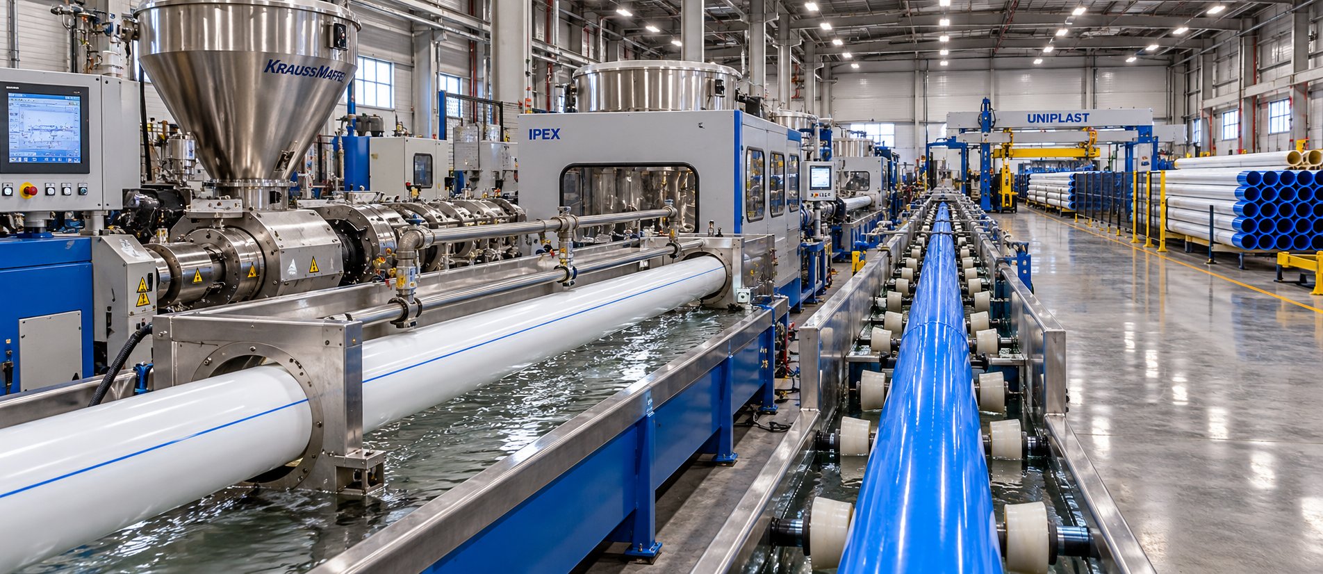
An HDPE pipe making machine is an integrated production line that converts raw high-density polyethylene resin into finished pipes through a continuous extrusion process. The system typically includes a single-screw extruder, a die head, a vacuum calibration tank, spray cooling tanks, a haul-off unit, a cutter, and a stacker or coiler, all working in sequence. Raw PE granules are fed into the extruder, melted under controlled heat and pressure, shaped into a tubular profile by the die, sized and cooled to precise dimensions, and then cut to length, producing seamless cylindrical pipes ready for deployment.
What sets this equipment apart from general-purpose plastic extrusion machinery is its specialized tooling and downstream configuration. Every component, from screw geometry to cooling tank length, is engineered specifically for polyethylene pipe production. A properly configured pe pipe production line can produce pipes ranging from small 16 mm conduits all the way up to large-diameter 1,200 mm infrastructure pipes, depending on extruder size and die setup.
Why HDPE Pipe Production Matters
The demand driving investment in polyethylene pipe production lines is massive and accelerating. The global HDPE pipes market was valued at USD 24.44 billion in 2025 and is projected to reach USD 37.93 billion by 2034, growing at a CAGR of 5.0%. Municipal water supply, gas distribution, sewage networks, agricultural irrigation, and telecommunications cable ducting all depend on a steady supply of high-quality HDPE pipe. Asia Pacific alone accounted for 46.84% of global market share in 2025, reflecting the sheer scale of infrastructure development fueling demand.
Why are HDPE pipes replacing traditional materials like concrete, steel, and ductile iron at such a rapid pace? The answer lies in a combination of physical properties that no single legacy material can match.
HDPE pipes offer a unique convergence of corrosion resistance, flexibility, fusion-weldable leak-free joints, and a service life exceeding 100 years, making them the preferred replacement for aging metal and concrete pipelines that suffer leakage rates of 20% to 30%.
These aren't just incremental improvements. HDPE piping systems create monolithic, leak-free connections where fused joints are actually stronger than the pipe wall itself. They resist chemical attack, biological growth, and root intrusion without any protective coating. They handle surge pressures up to twice their rated capacity and bend to accommodate ground movement without cracking. And because HDPE is lightweight, installation costs drop significantly compared to steel or concrete alternatives, especially with trenchless methods.
Producing pipes with these properties at scale, however, demands purpose-built extrusion equipment. You can't achieve the dimensional precision, wall thickness uniformity, and pressure ratings required by standards like ISO 4427 without an hdpe pipe extrusion machine specifically designed for the task. Every degree of melt temperature, every millimeter of vacuum calibration, and every meter-per-minute of haul-off speed directly influences whether the finished pipe meets specification or becomes scrap.
That relationship between machine capability and pipe quality is exactly what the following sections unpack, starting with the individual components that make up a complete extrusion line and what each one actually does.
Essential Components of an HDPE Pipe Extruder Machine
A specification sheet might list a dozen components and their ratings, but it rarely tells you why each one matters or how a weakness in one station cascades into defects at every station that follows. Think of the production line as a chain: the extruder melts, the die shapes, the calibration tank sizes, the cooling tanks solidify, the haul-off pulls, and the cutter finishes. If any single link underperforms, every link downstream inherits the problem. Here is what each component actually does, explained in practical terms rather than catalog shorthand.
The Extruder Unit and Its Core Elements
The single-screw extruder is the heart of every HDPE pipe making machine. It accepts solid PE granules and delivers a uniform, pressurized melt to the die head. Five subcomponents work together to make that happen:
Hopper. A funnel-shaped reservoir sits above the extruder throat, gravity-feeding pellets into the barrel. On basic lines, a simple open hopper does the job. More advanced setups integrate a gravimetric feeder between the hopper and the barrel inlet, metering pellets by weight rather than volume. This ensures a consistent feed rate and allows precise dosing of color masterbatch or additive concentrates.
Barrel. Picture a thick-walled, heated steel cylinder that houses the screw. The barrel features multiple independently controlled temperature zones, each equipped with ceramic band heaters and cooling channels. These zones establish a carefully profiled temperature gradient, lower near the feed throat to prevent premature melting and progressively higher toward the outlet to ensure complete plasticization. A well-designed barrel acts as the primary heat transfer surface and the pressure containment vessel for the entire melting process.
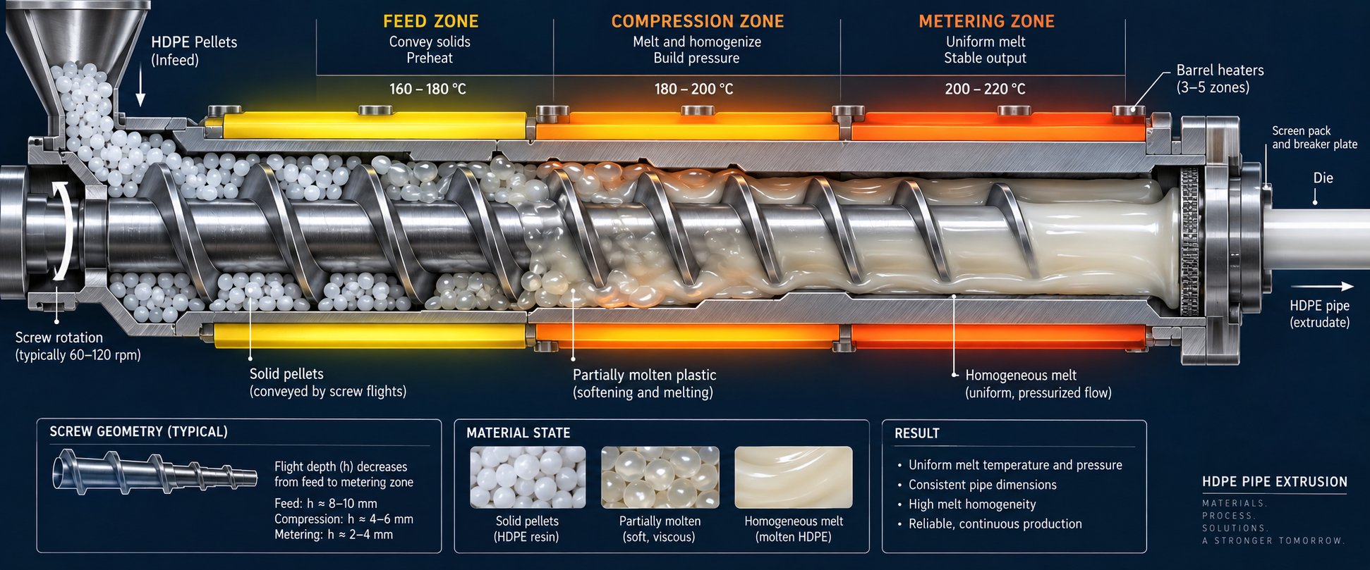
Screw. This single rotating element is where the real transformation happens. As it turns inside the barrel, the screw conveys pellets forward through three functionally distinct sections. The feed zone receives solid granules and compacts them. The compression zone gradually reduces channel depth, generating frictional shear heat that melts the resin. The metering zone stabilizes the fully molten polymer and delivers it at consistent pressure and flow rate toward the die.
Three geometric parameters define the screw's performance, and you'll encounter them on every spec sheet:
Screw diameter determines output capacity. A larger diameter means a larger channel cross-section, which translates directly into higher volumetric throughput per revolution. Pipe extruders commonly use screw diameters ranging from 45 mm for small-diameter tubing up to 120 mm and beyond for heavy-wall, large-bore pipes. Each step up in diameter corresponds to a roughly proportional increase in output and motor power requirements.
L/D ratio (length-to-diameter) governs melt quality. A screw measuring 2,640 mm long with an 80 mm diameter has an L/D of 33:1. A higher L/D ratio gives the polymer more residence time inside the barrel, improving melting, mixing, and homogenization. For HDPE pipe extrusion, industry practice settles on an L/D ratio of 30:1 to 33:1, providing thorough plasticization without the thermal degradation risks that come with excessively long barrel lengths.
Compression ratio describes how much the channel depth decreases from the feed zone to the metering zone. A higher compression ratio generates more shear heat and pressure, which suits semi-crystalline polymers like HDPE that need decisive melting energy. Getting this ratio wrong leads to either incomplete melting or excessive degradation.
Drive motor and gearbox. The motor provides rotational energy, typically an AC servo or variable-frequency drive offering precise speed control. The gearbox reduces motor speed while multiplying torque, allowing the screw to generate the high pressures needed to push viscous molten HDPE forward. Motor power on hdpe pipe extruder machines ranges from around 15 kW for small lines to 315 kW or more for large-diameter production systems.
Between the extruder outlet and the die head, most lines also include a screen changer that filters contaminants and degraded polymer particles, and sometimes a melt pump that stabilizes pressure pulsations. These two elements are easy to overlook, but they directly influence the surface quality and dimensional consistency of the finished pipe.
Die Head and Tooling
Once the melt exits the extruder, it flows as a single pressurized stream. The die head's job is to reshape that stream into a uniform, hollow cylinder. Modern HDPE pipe lines predominantly use spiral mandrel die heads, where the incoming melt splits into multiple feed ports that channel polymer into helical grooves carved into a central mandrel. As these spiral channels progress along the mandrel's length, their depth gradually decreases, forcing the polymer to merge into a continuous annular flow. The overlapping streams blend together, effectively eliminating weld lines and producing remarkably uniform wall distribution.
Why does this matter practically? Because wall thickness uniformity is the single most important dimensional attribute for pressure-rated pipe. An off-center die or poorly designed flow channel produces one side consistently thicker than the other. Under internal pressure, the thinner side becomes the failure point. At the die exit, adjustable centering bolts allow operators to fine-tune the annular gap, compensating for minor flow imbalances. Die temperature is also tightly controlled, typically held slightly below the metering zone temperature to prevent thermal degradation at the exit point.
Downstream Equipment Overview
Everything after the die head falls under "downstream equipment," and each station plays a non-negotiable role in turning a hot, soft tube into a rigid, dimensionally accurate pipe. Later sections of this guide will dive deep into each unit, but here is a brief orientation so you can see how the full production chain connects.
The vacuum calibration tank is where the pipe first acquires its precise dimensions. The still-soft extrudate enters a sealed, water-filled tank where reduced air pressure pulls the outer wall against a precision-machined calibration sleeve, locking in outer diameter and roundness. Get the vacuum level wrong, and you'll fight ovality and dimensional drift for the entire run.
Next, spray cooling tanks remove residual heat through multiple stages of water spray or immersion, solidifying the pipe's crystalline structure and preventing downstream deformation. Haul-off units use caterpillar-style dual-belt traction to grip the cooled pipe and pull it through the entire line at a precisely synchronized speed. The ratio between extruder output and haul-off speed directly controls wall thickness. The cutting unit, typically a planetary saw or chip-free cutter, travels with the moving pipe and cuts it to programmed lengths without stopping production. Finally, a stacker or coiler organizes the finished product: large-diameter rigid pipes are stacked for transport, while smaller-diameter flexible pipes are wound onto coils.
For quick reference, here is every major component of the hdpe extruder production line and its core function in one scannable list:
- Hopper and gravimetric feeder — stores resin and meters pellets into the barrel at a precise, consistent rate.
- Single-screw extruder (barrel + screw) — melts, compresses, and homogenizes HDPE into a uniform pressurized melt.
- Drive motor and gearbox — delivers controlled rotational energy and torque to the screw.
- Screen changer — filters contaminants, degraded particles, and foreign matter from the melt stream.
- Melt pump (optional) — stabilizes pressure fluctuations for smoother, more consistent output.
- Extrusion die head — shapes the melt into an annular pipe profile with uniform wall distribution.
- Vacuum calibration tank — sets outer diameter and roundness by pulling the soft pipe against a precision sizing sleeve.
- Spray cooling tanks — extract residual heat to solidify the pipe structure uniformly.
- Haul-off unit — pulls the pipe through the line at a constant speed, controlling wall thickness.
- Cutting unit — cuts pipe to programmed lengths on-the-fly without stopping production.
- Stacker or coiler — organizes finished pipe for storage and shipment.
Every component in this sequence is interdependent. A worn screw reduces melt quality, which the die head cannot correct. A misaligned calibration sleeve introduces ovality that the haul-off cannot fix. Understanding each unit's role and its limits is what separates a smoothly running production line from one plagued by recurring defects. The real question, though, is what actually happens to the resin as it moves through these machines, step by step, and how specific process settings at each stage determine whether you produce a flawless pipe or a reject.
Step-by-Step HDPE Pipe Extrusion Process Explained
Knowing what each component does is one thing. Understanding how resin actually transforms into a finished pipe as it passes through those components is something else entirely. The hdpe pipe manufacturing process is a carefully orchestrated sequence where temperature, pressure, speed, and vacuum must stay synchronized from the first pellet entering the hopper to the last cut at the saw. Miss a single parameter, and defects cascade through every meter of pipe that follows. Here is the pipe extrusion process step by step, broken down into three critical stages.
Raw Material Preparation and Feeding
Everything starts with resin selection. HDPE pipe grades are classified by their minimum required strength (MRS), and two grades dominate the market: PE80 (MRS of 8 MPa) and PE100 (MRS of 10 MPa). PE100 is the standard choice for pressure-rated water and gas pipes because it allows thinner walls at the same pressure rating, reducing both material cost and weight. Your choice of grade directly determines the temperature profile, screw speed, and die gap settings the pe pipe extrusion machine will need.
HDPE resin is typically supplied as pellets that absorb minimal moisture, so aggressive drying is rarely necessary. However, surface moisture from transport or storage can cause bubbles and surface defects in the finished pipe, so many operators pass pellets through a dehumidifying hopper dryer as a precaution, especially in humid climates.
Feeding involves more than just dropping pellets into the hopper. Most production lines use either a volumetric or gravimetric dosing system to introduce raw material and additives. Volumetric feeders meter by volume and work adequately for simple formulations, but gravimetric feeders measure by weight, compensating automatically for variations in pellet density or bulk flow. This matters because additives like carbon black masterbatch (typically dosed at 2% to 2.5% for UV protection in outdoor applications) and UV stabilizers need precise ratios. Too little carbon black means insufficient UV resistance; too much can degrade mechanical properties. A gravimetric blender ensures those ratios stay locked regardless of throughput fluctuations.
Plasticizing and Melt Extrusion Through the Die
Picture the pellets entering the barrel's feed throat. They're solid, room-temperature granules. Within seconds, they begin a controlled transformation. The barrel's multiple heating zones, typically four to six independently regulated segments, establish a progressive temperature gradient. The first zone near the feed section runs cooler, often around 160 to 180 degrees Celsius, to prevent premature melting that would block incoming material. Temperatures climb through each successive zone, reaching 190 to 220 degrees Celsius in the metering section, depending on resin grade and pipe specifications.
But here is a detail many operators overlook: barrel heaters alone don't do all the work. As the screw rotates, its compression zone generates significant frictional shear heat, sometimes contributing more thermal energy than the heaters themselves. This shear energy, combined with conductive heat from the barrel wall, melts the compacted pellet bed into a homogeneous fluid. The screw's metering zone then stabilizes this melt, building consistent pressure, typically in the range of 150 to 350 bar, to push it forward through a screen pack that filters contaminants and into the die head.
Inside the die, the melt splits across spiral flow channels carved into a central mandrel, then recombines into a seamless annular tube. Melt temperature control at this stage is critical. If the polymer is too hot, it degrades, producing a rough surface and reduced long-term strength. If it's too cool, incomplete fusion leaves weak points in the pipe wall. Operators monitor melt temperature at the die exit and adjust barrel zone settings and screw speed to keep it within a tight window, usually plus or minus 3 to 5 degrees Celsius of the target.
Sizing, Cooling, and Finishing
The moment the soft, still-molten tube exits the die lip, it enters the most dimensionally sensitive phase of the entire extrusion pipe machine line. Here, the pipe acquires its final shape, and every millimeter of tolerance matters.
The full production sequence from raw material to finished product follows these numbered stages:
- Vacuum calibration. The hot, pliable tube enters a sealed vacuum calibration tank filled with chilled water. Reduced air pressure, typically around negative 0.02 to 0.06 MPa, pulls the soft outer wall outward against a precision-machined stainless steel calibration sleeve. This sleeve defines the pipe's exact outer diameter and roundness. The vacuum level must remain constant; fluctuations produce dimensional drift and ovality that show up immediately in quality testing.
- Initial cooling and solidification. While still inside the calibration tank, the pipe's outer layer begins to solidify. The cooling water temperature here is carefully controlled, usually between 15 and 20 degrees Celsius. Cooling too aggressively creates thermal stress gradients across the pipe wall, which can lead to warping or residual stress that compromises long-term performance.
- Multi-stage spray cooling. After exiting the calibration tank, the pipe passes through one or more spray cooling tanks where water jets evenly remove residual heat. These tanks are partitioned into sections with independent water temperature controls, with the coolest water positioned at the pipe exit end. This counter-flow arrangement creates a gradual temperature decline that minimizes internal stress. The pipe must reach close to room temperature before encountering downstream mechanical forces.
- Haul-off traction. A caterpillar-style haul-off unit grips the cooled pipe with rubber-padded belts or tracks and pulls it through the entire line at a precisely regulated speed. This speed, synchronized with the extruder's output rate, is one of the primary controls for wall thickness. Slowing the haul-off makes walls thicker; speeding it up thins them. Modern haul-off units use servo drives capable of speeds up to 30 m/min, with clamping force adjustable to handle pipes of different diameters without surface damage.
- Online printing and marking. Before cutting, an inkjet or hot-foil printer applies continuous identification markings directly onto the pipe surface, including manufacturer name, material grade, diameter, pressure class, production date, and applicable standard. This marking is a regulatory requirement in most markets and provides full traceability.
- Cutting to length. A planetary cutter or chipless cutting machine clamps onto the moving pipe, travels with it at line speed, and makes a clean perpendicular cut at the programmed length. Planetary cutters rotate a blade around the pipe circumference, producing smooth, burr-free ends suitable for fusion welding without secondary finishing. For bell-end pipes used in push-fit drainage systems, an inline socketing machine heats and expands one end of each cut length before it reaches the stacker.
- Stacking or coiling. Rigid pipes larger than roughly 110 to 160 mm in diameter are transferred to a dump table or automatic stacker for bundling. Flexible pipes with smaller diameters and thinner walls are wound onto coils by an automatic winder synchronized to the line speed, with dual-station coilers allowing continuous production without stopping to change reels.
Every one of these stages feeds information back to the operator. Wall thickness readings from ultrasonic gauges, diameter data from laser measurement systems, and vacuum level indicators all provide real-time feedback. Experienced operators constantly fine-tune screw speed, haul-off rate, vacuum pressure, and cooling water flow to keep the pipe within specification. The process might look like a straight-line march from pellet to pipe, but in practice, it's a dynamic balancing act that demands constant attention.
What makes this balancing act even more complex is the sheer range of machine configurations available for different pipe sizes and applications. A line producing 32 mm irrigation tubing operates in an entirely different parameter universe than one extruding 800 mm water mains, yet both follow the same fundamental process. The key to navigating that complexity lies in understanding what the numbers on a specification sheet actually mean and how they translate to real-world production capability.
How to Read HDPE Pipe Machine Specifications
You've seen the spec tables — rows of numbers listing screw diameters, motor power, L/D ratios, and output ranges. They look authoritative, but what do those numbers actually tell you about production capability? Most manufacturers publish these tables without a word of explanation, leaving buyers to guess whether a 75 mm screw with a 33:1 L/D and a 110 kW motor is the right fit for their production goals. This section translates the most important hdpe pipe machine specifications into plain, practical terms so you can evaluate any spec sheet with confidence.
Understanding Screw Diameter and L/D Ratio
These two numbers appear on every hdpe extruder machine listing, and they reveal more about a line's capability than almost any other specification.
Screw diameter is the single biggest determinant of output capacity. The relationship isn't linear — it's geometric. Extrusion volume scales roughly with the square of the screw diameter, meaning even a modest increase delivers a disproportionately large jump in throughput. A 50 mm screw diameter for pipe extrusion might process 80 to 150 kg/h, while stepping up to a 90 mm or 120 mm screw pushes output into several hundred kilograms per hour. In practical terms, smaller screws (45 to 65 mm) handle pipe diameters from 16 mm up to about 110 mm, mid-range screws (65 to 90 mm) cover the 63 mm to 315 mm pipe range, and large screws (90 mm and above) drive production of heavy-wall pipes reaching 630 mm to 1,200 mm in outer diameter.
L/D ratio tells you how much working length the screw has relative to its diameter. A 75 mm screw that is 2,475 mm long has an L/D of 33:1. Why does this matter? A longer L/D ratio extends the polymer's residence time inside the barrel, allowing more thorough heat distribution, better mixing, and a more homogeneous melt. For HDPE pipe production, you'll typically see L/D ratios between 30:1 and 36:1. Values below 30:1 risk incomplete plasticization, leading to unmelted particles embedded in the pipe wall. Values significantly above 36:1 increase energy consumption and can introduce thermal degradation from excessive residence time. When comparing two machines with the same screw diameter, the one with the higher L/D ratio will generally produce a better-quality melt — but at the cost of a longer barrel, higher power draw, and greater sensitivity to screw deflection.
Pipe Diameter Range and Output Capacity
Spec sheets always list a pipe diameter range, something like "16–630 mm." Sounds straightforward — but that range doesn't mean a single machine covers it all. Typically, a manufacturer's catalog groups several distinct extruder models under one product family, each model targeting a narrower slice of that range. A 65 mm extruder configured with the appropriate die tooling might produce 20 mm to 110 mm pipes, while a 90 mm extruder with different tooling handles 75 mm to 400 mm. Always ask which specific extruder model corresponds to which pipe diameter segment.
Output capacity, measured in kg/h, represents the mass of HDPE the extruder can process per hour under optimal conditions. But what buyers really want to know is meters of pipe per hour, and that depends entirely on the pipe's geometry. Here is a general approach to estimate it yourself:
First, calculate the cross-sectional area of the pipe wall using the formula: A = π × (OD - WT) × WT, where OD is the outer diameter and WT is the wall thickness, both in meters. Multiply that area by the HDPE density (approximately 950 kg/m³) to get the mass per linear meter. Then divide the machine's output capacity (kg/h) by that mass-per-meter figure. For example, a pipe with a 110 mm outer diameter and 10 mm wall thickness has a cross-sectional area of roughly 0.00314 m², yielding about 2.98 kg per meter. A machine rated at 300 kg/h would theoretically produce around 100 meters per hour of that specific pipe — before factoring in startup waste, speed limitations from cooling capacity, and real-world efficiency losses that typically reduce effective output by 10% to 20%.
This calculation highlights an important reality: pipe extrusion line output capacity is not fixed. The same extruder produces far more meters per hour of thin-wall, small-diameter pipe than it does of thick-wall, large-diameter pipe, even though the kg/h figure stays the same. Always evaluate output capacity in the context of your target pipe dimensions, not as an absolute number.
Reading a Machine Specification Table
Imagine you're reviewing a manufacturer's catalog and encounter a table like the one below. Instead of scanning past the numbers, you can now extract real meaning from each column.
| Specification | Small-Diameter Line | Mid-Range Line | Large-Diameter Line |
|---|---|---|---|
| Screw Diameter | 50–65 mm | 65–90 mm | 90–120 mm+ |
| L/D Ratio | 30:1 – 33:1 | 33:1 – 36:1 | 30:1 – 33:1 |
| Motor Power | 15–55 kW | 55–160 kW | 160–315 kW |
| Pipe Diameter Range | 16–110 mm | 75–400 mm | 315–1,200 mm |
| Output Capacity | 80–200 kg/h | 200–500 kg/h | 500–1,200+ kg/h |
Here is how to use this table in practice. Start with the pipe diameter range column — that immediately tells you whether the machine covers your target product. Next, check screw diameter and motor power together; they should scale proportionally. A 90 mm screw paired with only a 55 kW motor would be underpowered, struggling to maintain consistent melt pressure at higher throughput rates. The L/D ratio confirms melt quality potential: for HDPE, you want at least 30:1. Finally, output capacity gives you the throughput ceiling, but remember to convert it to meters per hour using your specific pipe dimensions before comparing it to your production targets.
One detail worth noting: large-diameter lines sometimes show a slightly lower L/D ratio than mid-range lines. That's because very large screws face increased deflection risk at longer lengths, so manufacturers balance melt quality against mechanical reliability. The trade-off is usually compensated by optimized screw geometry and additional mixing elements rather than simply extending barrel length.
Specifications paint a picture of what a machine can do in ideal conditions. What determines whether it delivers that performance consistently shift after shift — and whether two operators with the same line produce wildly different results — comes down to something the spec sheet never shows: the level of automation controlling the process.
Automation Levels in HDPE Pipe Production Lines
Two factories buy the same hdpe extrusion machine with identical screw diameters, identical motor power, and identical die tooling. One produces pipe with wall thickness variations under 3%, runs with a skeleton crew, and generates less than 1% scrap. The other fights constant dimensional drift, needs an operator stationed at every unit, and wastes material by the barrel load. The difference? Automation. The level of process control integrated into your production line shapes output consistency, labor costs, and per-unit economics more dramatically than almost any mechanical specification. Yet virtually no manufacturer's website explains the practical distinctions between manual, semi-automatic, and fully automatic configurations. Here is that missing explanation.
Manual and Semi-Automatic Lines
On a basic manual extrusion line, the operator is the control system. Temperature set points for each barrel zone are dialed in by hand on analog controllers. The operator watches the pipe exit the die, judges its appearance visually, and adjusts screw speed or haul-off rate based on experience. Cutting happens when the operator triggers the saw at measured intervals, and quality inspection means pulling a sample, grabbing calipers, and checking dimensions against a spec sheet. It works — and for small-scale operations producing limited pipe runs, it can be perfectly adequate.
The limitations, however, show up quickly as production volume or quality demands increase. Manual temperature control drifts between checks. Visual inspection catches obvious defects but misses gradual wall thickness variation. Operator fatigue during long shifts introduces inconsistency. And every time you change operators, you effectively change the control system, because output quality becomes a function of individual skill rather than repeatable process parameters.
Semi-automatic lines address the most critical pain points by introducing PLC-based controls for temperature regulation, automated cutting cycles, and basic process alarms. A PLC controlled pipe extrusion line replaces analog dials with digital set points, maintains barrel zone temperatures within tighter tolerances through closed-loop feedback, and triggers the cutter automatically based on encoder-measured pipe lengths. The operator still manages startup, shutdown, die changes, and responds to alarms, but the system handles the repetitive precision tasks that human attention handles poorly over extended shifts.
Where do these options fit economically? Manual lines carry the lowest capital cost and suit startup operations, small workshops, or markets where labor is inexpensive and production volumes stay below a few hundred meters per shift. Semi-automatic lines occupy the middle ground — moderate investment with meaningful gains in consistency and reduced operator dependency, making them a practical choice for mid-volume producers targeting standard pipe specifications.
Fully Automatic Production Lines
Step into a fully automatic pipe production line, and the difference is immediately visible. Operators monitor rather than intervene. The system runs itself within programmed parameters, correcting deviations faster than any human could respond.
What does "fully automatic" actually mean in practice? It means the integration of several interconnected control technologies:
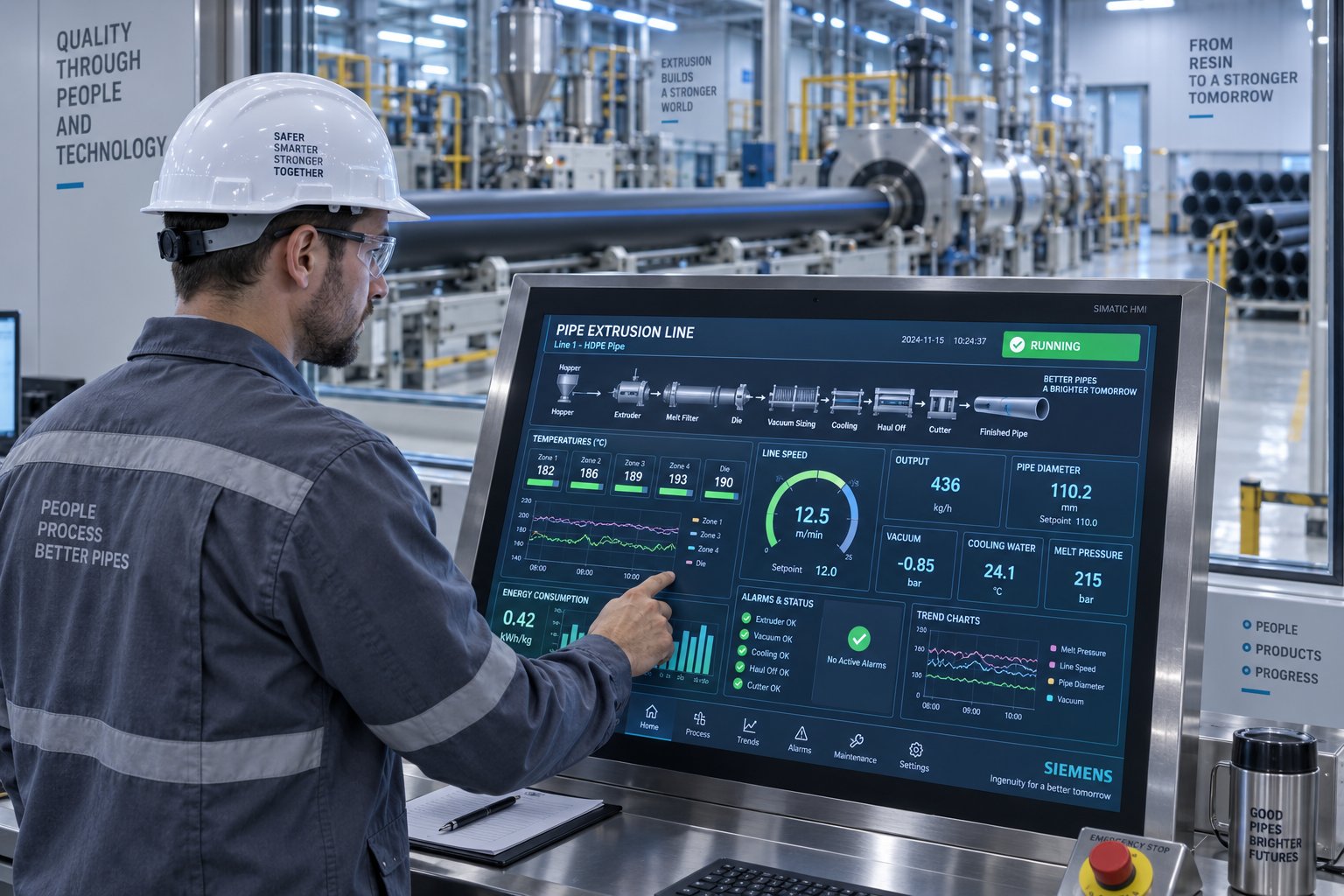
- PLC/HMI control panels — centralized touchscreen interfaces that display and manage every process variable across the entire line, from extruder barrel temperatures to haul-off speed, with recipe storage for rapid product changeovers.
- Gravimetric dosing — weight-based material feeders that automatically maintain precise resin-to-additive ratios regardless of throughput fluctuations, eliminating the mixing inconsistencies that plague volumetric systems.
- Ultrasonic wall thickness measurement — sensors positioned after the calibration tank continuously measure wall thickness at multiple points around the pipe circumference. When wall thickness scanners detect deviation, the system automatically adjusts die centering or haul-off speed to bring dimensions back to target.
- Servo-driven haul-offs — precision servo motors replace conventional AC drives, delivering speed stability within fractions of a percent and enabling automatic speed adjustments based on real-time wall thickness feedback.
- Automated stacking and coiling — finished pipes are counted, bundled, and stacked or wound onto coils without manual handling, reducing labor at the end of the line while eliminating handling damage.
The economic impact of this integration is substantial. Automatic wall thickness control alone can reduce material overuse by 1% to 2% — and on a line running thousands of kilograms per day, that saving pays for the scanner equipment in less than a year. Scrap rates drop because the system catches drift before it produces out-of-spec pipe. Labor requirements fall significantly: where a manual line might need four to five operators per shift, a fully automatic hdpe pipe making machine can run with one or two. And output consistency improves dramatically, which matters not just for quality but for standards compliance, where every pipe must fall within tight dimensional tolerances.
Industry 4.0 and Smart Extrusion
Full automation handles the production floor. Industry 4.0 extends visibility and intelligence beyond it. Imagine sitting in an office — or another country — and monitoring every parameter of your extrusion line in real time. That capability is no longer theoretical. Modern smart extrusion systems leverage IoT sensors, AI-driven analytics, and networked control architectures to create what the industry calls connected or intelligent production lines.
Three capabilities define this emerging tier of automation. Real-time production monitoring uses IoT-connected sensors to stream temperature, pressure, speed, and dimensional data to cloud-based dashboards accessible from any device. Predictive maintenance applies AI algorithms to equipment data — motor current draw, gearbox vibration patterns, barrel heater performance — to forecast component failures before they cause unplanned downtime. Instead of replacing a heater band after it burns out mid-shift, the system flags declining performance days in advance, allowing scheduled replacement during planned maintenance windows. Data logging for quality traceability records every process parameter for every meter of pipe produced, creating a digital production history that satisfies increasingly stringent quality auditing requirements and enables root-cause analysis when defects are detected downstream.
These features are beginning to appear in premium HDPE pipe lines, though adoption remains uneven. The initial investment is higher, and the systems demand a workforce comfortable with digital interfaces and data interpretation — a challenge that echoes across the broader manufacturing sector. Still, the trajectory is clear: the combination of reduced waste, lower unplanned downtime, and verifiable quality documentation makes smart extrusion an increasingly compelling proposition for high-volume producers.
The following comparison table summarizes how these three automation levels stack up across the factors that most directly affect your production economics:
| Factor | Manual Line | Semi-Automatic Line | Fully Automatic Line |
|---|---|---|---|
| Labor Requirement (per shift) | 4–5 operators | 2–3 operators | 1–2 operators |
| Output Consistency | Variable, operator-dependent | Improved, PLC-stabilized | High, closed-loop controlled |
| Wall Thickness Control | Manual measurement, periodic | Manual measurement, alarm-assisted | Automatic, real-time ultrasonic |
| Scrap Rate | Higher (3–5%+) | Moderate (2–3%) | Low (under 1–2%) |
| Initial Investment Level | Lowest | Moderate | Highest |
| Best Suited For | Small-scale, low-volume startups | Mid-volume, standard products | High-volume, standards-critical production |
| Industry 4.0 Readiness | None | Limited retrofit potential | Native integration possible |
Choosing the right automation level isn't simply a matter of budget — it's a strategic decision that determines your cost structure for years. A fully automatic line costs more upfront but delivers lower per-meter production costs at scale. A manual line preserves capital but limits your ability to compete on consistency or certify production to demanding international standards. The right answer depends on your target applications, the standards your pipes must meet, and the production volumes that justify the investment — factors that the next section explores in detail.
Applications and Quality Standards for HDPE Pipes
Target applications and the standards governing them are what ultimately dictate how your extrusion line must be configured. A pipe destined for potable water distribution faces entirely different dimensional tolerances, pressure classes, and material requirements than one routed underground as cable ducting. Understanding these connections prevents a costly mismatch between machine capability and market demand.
Infrastructure and Utility Applications
HDPE pipe for water supply represents the largest single market segment, encompassing both potable and non-potable systems. Municipal water networks typically specify pipes in the 90 mm to 630 mm diameter range using PE100 grade resin, with hdpe pipe pressure ratings from 6 bar (SDR 26) up to 25 bar (SDR 7.4) depending on operating conditions. Producing these pipes demands an extrusion line with precise wall thickness control, because the Standard Dimensional Ratio (SDR) — the ratio of outer diameter to wall thickness — directly determines a pipe's maximum operating pressure through Lame's formula. Even small deviations in wall uniformity can push a pipe outside its rated pressure class.
Natural gas distribution imposes even stricter requirements. Gas pipes exclusively use PE100 or PE100-RC (Resistant to Crack) grades and feature distinctive orange color coding for immediate visual identification during installation. Pipe diameters for gas networks typically range from 20 mm to 315 mm, with SDR 11 (16 bar) being a common specification. The extrusion line must handle these specialized resins while maintaining the slow crack growth resistance properties that gas applications demand.
Beyond pressure systems, HDPE pipes serve sewage and drainage networks (typically 110 mm to 1,200 mm, lower pressure ratings or gravity flow), agricultural irrigation (20 mm to 110 mm, often coilable), and telecommunications cable ducting (32 mm to 110 mm, smooth or ribbed interior). Each application pushes different aspects of machine capability — irrigation lines prioritize high-speed output of small-diameter coilable pipe, while large sewage pipes demand heavy extruders with massive cooling capacity.
Key Pipe Standards and Certifications
Your extrusion line doesn't just produce pipe — it produces pipe that must comply with specific dimensional and performance standards. Failing to meet those standards means your product cannot be sold into regulated markets, regardless of how efficiently you produced it.
For potable water applications, ISO 4427:2019 stands as the definitive international standard, covering polyethylene piping systems for water supply with operating temperatures up to 45 degrees Celsius and maximum working pressures up to 25 bar. The standard mandates permanent marking on every pipe — material grade (PE80 or PE100), SDR value, production date, and manufacturer identification — for complete traceability. In European markets, EN 12201 provides largely harmonized requirements with regional regulatory nuances. For the Indian market, IS 4984 specifies requirements for HDPE pipes used in water supply, while German standards DIN 8074 (dimensions) and DIN 8075 (general quality requirements) govern European specifications with particular precision.
Gas distribution follows ISO 4437 internationally and ASTM D2513 in North American markets. These standards demand comprehensive stress crack resistance testing and long-term hydrostatic strength verification that go well beyond what water pipe standards require. Additional regional frameworks — including AS/NZS 4130 for Australia, GB/T 13663 for China, and AWWA C901/C906 for U.S. municipal systems — add further layers of compliance depending on your target geography.
What ties all of this back to the machine? Standards compliance is fundamentally a function of extrusion precision. Wall thickness tolerances specified in hdpe pipe standards like ISO 4427 are tight, and meeting them consistently requires accurate die centering, stable vacuum calibration, synchronized haul-off speed, and reliable online measurement. A machine that drifts even fractionally outside these tolerances produces non-compliant pipe — and non-compliant pipe is unsaleable scrap.
Multi-Layer Co-Extrusion for Specialized Pipes
Some applications demand more than a single-layer pipe can deliver. A multi layer hdpe pipe extrusion line integrates two or more extruders feeding into a single co-extrusion die head, producing pipes with distinct functional layers in a single pass. The most common configuration uses a main extruder for the structural PE100 core and a smaller co-extruder to apply a thin outer skin or colored identification stripe.
Practical examples include pipes with a protective outer layer of virgin material over a core containing recycled HDPE, pipes with colored co-extruded stripes (blue for water, orange for gas, green for sewer) that eliminate the need for post-production printing, and pipes with UV-resistant outer layers bonded to a cost-optimized inner structure. Co-extrusion adds mechanical complexity and requires precise synchronization between extruders, but it opens access to premium market segments and enables material cost optimization strategies that single-layer lines simply cannot achieve.
The following table maps the major application categories to the machine and material specifications they typically require, giving you a quick reference for matching your target market to the right production configuration:
| Application | Typical Pipe Diameter Range | Common Pressure Class (SDR) | Material Grade | Key Standards |
|---|---|---|---|---|
| Potable Water Supply | 90–630 mm | SDR 11 (16 bar) to SDR 17 (10 bar) | PE100 | ISO 4427, EN 12201, IS 4984 |
| Natural Gas Distribution | 20–315 mm | SDR 11 (16 bar), SDR 17.6 | PE100 / PE100-RC | ISO 4437, ASTM D2513, EN 1555 |
| Sewage and Drainage | 110–1,200 mm | SDR 26 (6 bar) or non-pressure | PE80 / PE100 | ISO 4427, EN 12201, ASTM F714 |
| Agricultural Irrigation | 20–110 mm | SDR 13.6 (10 bar) to SDR 21 (6 bar) | PE80 / PE100 | ISO 4427, IS 4984 |
| Cable Ducting | 32–110 mm | Non-pressure or low-pressure | PE80 / PE100 | EN 61386, regional telecom specs |
| Industrial Fluid Transport | 63–400 mm | SDR 11 (16 bar) to SDR 9 (20 bar) | PE100 | ISO 4427, ASTM D3035 |
Matching your target application to the correct column in this table is the starting point for configuring an extrusion line. The pipe diameter range determines extruder size. The pressure class dictates how precisely the machine must control wall thickness. The material grade influences screw design and temperature profiles. And the standards column tells you exactly which dimensional and performance tolerances your line must consistently hit — tolerances that hold only as long as your equipment remains in peak condition. That reality brings a critical but often overlooked topic into focus: what it actually costs to keep an extrusion line running year after year, from energy consumption to the wear components that quietly erode production quality if neglected.
Energy Efficiency, Maintenance, and Total Cost of Ownership
The purchase price on a quotation sheet is just the opening chapter of what you'll actually spend. Energy bills, spare parts, unplanned downtime, and operator training accumulate quietly over the years, and for many producers, these running costs eventually dwarf the original equipment investment. Yet walk through any manufacturer's website, and you'll find detailed spec tables, glossy production photos — and virtually nothing about what happens financially after the machine lands on your factory floor. This section fills that gap, covering the three cost drivers that shape long-term profitability: power consumption, hdpe pipe machine maintenance, and total cost of ownership.
Power Consumption Patterns and Efficiency
Electricity is the single largest recurring expense on any HDPE pipe extrusion line, and it scales dramatically with pipe size. A small-diameter line running a 50 mm screw might draw 15 to 30 kW from its main drive motor. Step up to a mid-range system producing 200 mm to 400 mm pipes, and motor power climbs to 110 to 160 kW. Large-diameter lines extruding 630 mm to 1,200 mm pipes can demand 250 to 315 kW just for the extruder motor — before adding the energy consumed by heater bands, vacuum pumps, water chillers, haul-off drives, and cutting systems. In total, the extruder motor typically accounts for 60% to 70% of the entire line's electricity consumption, making drive efficiency the highest-leverage target for energy savings.
Three technologies are reshaping how energy efficient pipe extrusion lines manage that demand:
Permanent magnet servo motors. Traditional AC asynchronous motors paired with gearboxes lose significant energy through mechanical friction and heat. Permanent magnet synchronous servo drives eliminate the gearbox entirely, boosting transmission efficiency above 95% and delivering 10% to 20% reduction in energy consumption compared to conventional setups. Speed control accuracy reaches plus or minus 0.5%, which also improves extrusion stability and reduces melt temperature fluctuations.
Advanced barrel heating. Conventional cast aluminum or mica heater bands convert only 40% to 50% of their electrical input into useful heat — the rest radiates into the factory air. Electromagnetic induction heating systems generate heat directly within the barrel wall through eddy currents, achieving thermal efficiencies above 85%. Ceramic infrared heating rings offer a similar improvement path, with lower thermal inertia for more precise zone control and approximately 15% energy savings. Both technologies support independent zone temperature control, preventing the localized overheating that degrades polymer quality.
Optimized screw design. A screw engineered specifically for HDPE — with a tuned compression ratio, barrier geometry, and appropriate L/D ratio — achieves thorough plasticization at lower screw speeds and reduced shear heat input. That means the motor works less hard, and the cooling system needs to remove less excess thermal energy. The combination of the right screw geometry with efficient drive technology creates a compounding effect: less energy in, less waste heat out, and better melt quality simultaneously.
Beyond individual components, modern lines use variable-frequency linkage control to coordinate extruder, haul-off, and cutting unit speeds, eliminating the energy waste that occurs when downstream equipment runs faster or slower than it needs to. Closed-loop cooling water systems with variable-frequency pumps and plate heat exchangers adjust flow rates automatically based on pipe specifications, avoiding the overcooling that wastes both water and electricity. Together, these system-level optimizations can reduce comprehensive energy consumption from roughly 0.52 kWh/kg to around 0.42 kWh/kg on a well-integrated PE pipe production line — a difference that saves hundreds of thousands of kilowatt-hours annually on a line running at scale.
Maintenance Requirements and Troubleshooting
Imagine your line is running smoothly, hitting target dimensions, producing minimal scrap. Then, gradually, you notice wall thickness drift. Surface roughness creeps in. Output drops even though screw speed hasn't changed. These aren't random problems — they're signals that wear components are degrading, and ignoring them only accelerates the decline.
Routine maintenance on an HDPE pipe extrusion line follows a predictable rhythm. Here are the checkpoints that keep production on track:
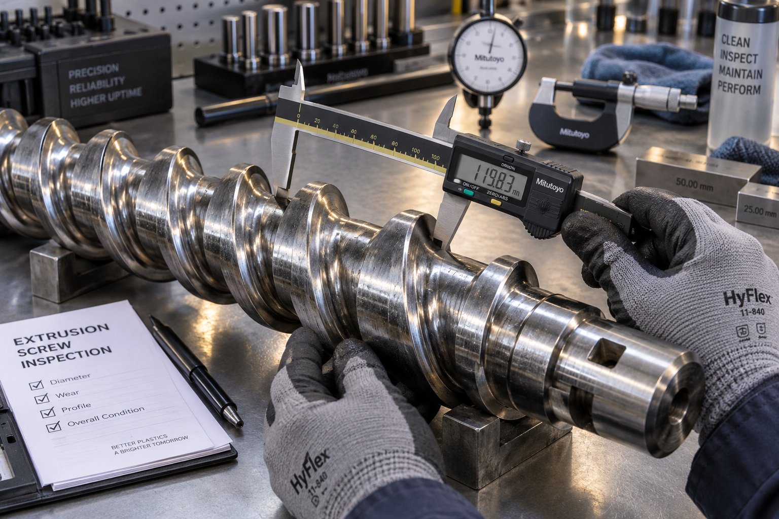
- Screw and barrel inspection — Measure barrel bore diameter and screw flight outer diameter at regular intervals (typically every 3,000 to 5,000 operating hours) to track clearance growth. As the gap between screw and barrel widens, more melt slips backward instead of being pumped forward, reducing throughput and increasing discharge temperature.
- Heater band condition — Check resistance and surface contact of all barrel heater bands. A failed or partially failed heater creates a cold zone that disrupts the temperature profile, causing uneven melting and visible defects.
- Die cleaning and inspection — Remove polymer buildup from die flow channels and inspect for erosion or scoring that disrupts uniform flow distribution. Even minor deposits near the die lip produce streaks or thickness variation.
- Haul-off calibration — Verify belt or track condition, clamping pressure, and speed accuracy. Worn belts slip, causing intermittent speed fluctuations that translate directly into wall thickness inconsistency.
- Vacuum pump service — Inspect seals, check oil levels, and verify that vacuum levels remain stable. Degraded vacuum performance causes dimensional drift and ovality in the calibration section.
- Cooling system maintenance — Clean spray nozzles, inspect water filtration, and verify chiller performance. Blocked nozzles create uneven cooling patterns that warp the pipe or introduce residual stress.
- Screen changer and breaker plate — Replace clogged screens before pressure drop affects output stability. Track pressure differential across the screen pack as an early warning indicator.
- Gearbox oil and drive components — Monitor oil condition and temperature, and check for unusual vibration or noise that signals bearing wear.
When problems do appear, a structured troubleshooting approach saves hours of guesswork. Uneven wall thickness typically traces back to die misalignment, inconsistent haul-off speed, or uneven melt temperature distribution — check die centering bolts, haul-off belt condition, and barrel zone temperatures in that order. Surface roughness often indicates melt fracture from excessive shear at the die exit; reducing screw speed slightly or raising die temperature can resolve it. Melt fracture, visible as a sharkskin or wavy texture, responds to adjustments in die gap, melt temperature, or the addition of processing aids. Inconsistent output — where kg/h fluctuates despite stable settings — points to feeding problems (bridging in the hopper, inconsistent pellet flow) or advanced screw and barrel wear where clearance has opened enough to cause melt backflow.
The critical insight across all these scenarios is that screw and barrel condition directly drives production quality. Worn flights, scored barrel surfaces, and excessive clearance don't just reduce output — they introduce the very defects that cause scrap and standards failures. Catching wear early through regular measurement and trending is vastly less expensive than dealing with an emergency shutdown when quality collapses mid-run.
Total Cost of Ownership Beyond Purchase Price
The quotation you receive covers the equipment itself. The actual cost of running an HDPE pipe making machine over its productive life includes at least five additional categories that many buyers underestimate:
Installation and commissioning. Site preparation, electrical connections, water supply infrastructure, and the manufacturer's commissioning team all carry costs beyond the machine price. A large-diameter line may require foundation reinforcement to handle equipment weight and vibration.
Operator training. Automated or not, your line is only as effective as the people running it. Initial training during commissioning covers basic operation, but developing skilled operators who can troubleshoot, optimize process parameters, and manage product changeovers efficiently requires ongoing investment. The shift from manual to fully automatic lines doesn't eliminate the need for skilled personnel — it shifts the skill requirement from manual dexterity to process understanding and digital literacy.
Spare parts inventory. Maintaining an adequate stock of critical wear components prevents expensive production stoppages. Heater bands, thermocouple sensors, screen packs, haul-off belts, and cutting blades are consumables with relatively predictable replacement cycles. But the components with the most significant impact on both production quality and operating cost are the screw and barrel.
The screw and barrel are the most impactful wear components in any HDPE pipe extrusion line — their condition directly determines melt quality, output consistency, energy efficiency, and ultimately the dimensional accuracy of every meter of pipe produced.
Pipe extrusion screw and barrel replacement is not a matter of if but when. Abrasive fillers, glass fiber reinforcement in some formulations, and the sheer volume of polymer processed over thousands of hours gradually erode screw flights and enlarge barrel bore diameter. When clearance grows beyond acceptable limits, performance degrades in ways that no amount of process adjustment can compensate for. Planning for this eventuality means identifying reliable suppliers who can provide replacement screws and barrels matched to your specific extruder model, resin type, and production demands. NANHAIYA, for example, specializes in custom and replacement single screw barrels designed for pipe extrusion lines, offering components engineered to restore or upgrade extruder performance when wear eventually takes its toll. Sourcing from a specialist with pipe extrusion experience ensures the replacement barrel's metallurgy, bore tolerance, and heat treatment match the demands of continuous HDPE processing — details that generic suppliers often overlook.
Power costs. As outlined earlier, electricity dominates operating expenses. Over a 10-year equipment lifespan, cumulative energy costs can exceed the original purchase price of the line, particularly for large-diameter systems running around the clock. Every efficiency gain — from servo drives to optimized screw geometry to proper barrel insulation — compounds over those years into substantial savings.
Planned downtime and preventive maintenance. Scheduling regular maintenance windows rather than reacting to failures keeps total downtime predictable and manageable. An effective preventive maintenance program, including periodic screw and barrel measurement, heater band testing, and cooling system service, typically costs a fraction of a single unplanned breakdown. Industry benchmarks suggest that well-maintained extrusion lines achieve overall equipment effectiveness (OEE) above 85%, compared to 60% to 65% for lines running on a reactive maintenance approach.
Thinking about total cost of ownership reframes the purchasing decision entirely. A lower-priced machine with inefficient drives, inferior screw metallurgy, and limited spare parts availability might look attractive on a quote but cost significantly more over its operational life than a premium line with energy-efficient components, durable wear parts, and a well-established supply chain for replacements. The smartest investment isn't the cheapest machine — it's the one that delivers the lowest cost per meter of compliant pipe over a decade of continuous production.
Cost optimization, though, isn't only about maintaining current equipment. Emerging technologies are actively rewriting the economics of HDPE pipe extrusion, from advanced measurement systems that eliminate material waste to sustainable production methods that reduce both raw material costs and environmental impact.
Emerging Trends and Innovations in HDPE Pipe Extrusion
Every percentage point of material saved, every defect caught before it becomes scrap, and every kilogram of recycled resin successfully processed represents a tangible competitive advantage. The technologies driving these gains aren't futuristic concepts sitting in research labs — they're already reshaping how leading producers configure and operate their HDPE pipe making machines. Here is where the industry is heading, and what it means for your next equipment decision.
Advanced Process Control and Measurement
Precision starts at the feeder. Gravimetric dosing systems weigh incoming material in real time, comparing actual feed rates against programmed targets and adjusting motor speed to compensate for variations in pellet density, hopper level, or throughput changes. Unlike volumetric feeders that meter by volume alone, gravimetric blenders lock in exact resin-to-additive ratios down to fractions of a percent. When you're dosing carbon black masterbatch at 2.5% and UV stabilizer at 0.3%, even a 0.2% drift introduces measurable inconsistency across a full production shift. Gravimetric control eliminates that drift, delivering repeatable formulations pipe after pipe.
The real breakthrough in process measurement, however, is happening downstream. Ultrasonic wall thickness gauging systems position multiple transducers around the pipe circumference immediately after the calibration tank. Each transducer emits an ultrasonic pulse that travels through the pipe wall, reflects off the inner surface, and returns — with the round-trip time revealing wall thickness at that specific point. Modern systems capture thousands of measurements per second across multiple positions simultaneously, building a complete real-time thickness profile of the pipe as it moves through the line. When the system detects wall thickness drifting outside tolerance, it feeds correction signals directly to the die centering actuators or haul-off speed controller, closing the loop before out-of-spec pipe accumulates.
Imagine the waste reduction this enables. Without inline measurement, an operator might not catch gradual thickness drift for several minutes — during which tens or hundreds of meters of non-compliant pipe have already been produced. With ultrasonic gauging running at rates exceeding 10,000 measurements per second, deviations are identified and corrected within seconds. Multi-layer pipes benefit as well, since ultrasonic signals generate distinct echoes at each layer boundary, allowing individual layer thicknesses to be monitored independently.
Complementing thickness measurement, laser diameter gauges use opposing laser scan heads to measure the pipe's outer diameter and ovality continuously. Together, these two measurement technologies — ultrasonic for wall thickness and laser for outer geometry — provide the complete dimensional picture that standards like ISO 4427 demand. The data they generate also feeds directly into quality traceability systems, creating a permanent digital record of every pipe's dimensions throughout production.
Sustainable Production Practices
Sustainability in pipe manufacturing isn't just a marketing narrative — it's a technical challenge with real engineering constraints. The growing push to incorporate recycled HDPE (rHDPE) into pipe production introduces variables that virgin resin lines never encounter, and your extrusion equipment must be prepared to handle them.
Research into recycled HDPE pipe production highlights several core challenges. The quality of recycled feedstock varies significantly depending on the waste source, collection method, and reprocessing history. Contaminants — trace metals, incompatible polymers, pigments, and degraded material fractions — can compromise the long-term mechanical performance that pressure pipe applications demand. Additionally, every reprocessing cycle shortens polymer chain length, reducing properties like slow crack growth resistance and long-term hydrostatic strength that are critical for pressure-rated pipe. The feasibility of using recycled content depends on the quantity in the blend, the pipe grade, and the designated application.
What does this mean for machine configuration? Processing rHDPE demands tighter filtration — finer screen packs and continuous screen changers capable of handling higher contaminant loads without frequent shutdowns. Screw designs may need modified compression ratios or additional mixing sections to homogenize blends of virgin and recycled resin that have different melt flow characteristics. Gravimetric dosing becomes even more critical, because recycled pellet density varies more than virgin resin, and maintaining consistent blend ratios requires weight-based accuracy rather than volume-based estimation.
That said, the environmental benefits are significant. Using recycled material in pipe manufacturing reduces resource consumption, lowers energy usage compared to virgin resin production, and decreases acidification impact. Multi-layer co-extrusion lines offer an elegant compromise: a structural core layer made from carefully blended rHDPE, enclosed within inner and outer skin layers of certified virgin PE100 that satisfy standards requirements for surface quality and long-term performance. This approach allows manufacturers to incorporate recycled content while still meeting the mechanical and dimensional specifications that regulated applications require.
Energy-efficient extrusion components contribute to sustainability targets from a different angle. Servo-driven extruders, electromagnetic barrel heaters, and variable-frequency cooling systems collectively reduce the carbon footprint per meter of pipe produced — a metric that an increasing number of infrastructure procurement contracts now evaluate alongside price and technical compliance.
High-Speed Extrusion and Productivity Gains
Speed is seductive — but in pipe extrusion, it's also constrained. You can push material through the die faster, but the pipe still needs to be fully cooled and dimensionally stable before the haul-off grips it and the saw cuts it. The bottleneck in high speed hdpe pipe extrusion isn't the extruder — it's the cooling system. Every gain in line speed requires a corresponding gain in cooling capacity, or the pipe exits the cooling section still warm and soft, leading to ovality, dimensional drift, and residual stress.
Modern production lines are attacking this constraint from multiple directions. Improved screw designs with optimized barrier geometry and advanced mixing elements deliver more homogeneous melts at higher throughput rates, reducing the need to slow down for quality reasons. Extended cooling tanks with intensified spray patterns and turbulent water flow accelerate heat extraction from the pipe wall. Some manufacturers now use counter-flow cooling configurations where the coldest water contacts the pipe last, maximizing the temperature differential and heat transfer rate throughout the cooling path. Faster servo-driven haul-offs track speed changes precisely, while high-speed planetary cutters keep pace with line speeds that would have overwhelmed older saw designs.
For small-diameter coilable pipes, these combined improvements have pushed production speeds well beyond traditional benchmarks, with some advanced lines running at rates that would have been considered impractical just a decade ago. Larger-diameter pipes, with their greater wall mass and slower heat dissipation, see more modest speed gains — but even incremental improvements translate to meaningful productivity increases when multiplied across continuous 24/7 production schedules.
The interplay between speed, quality, and cooling capacity is the defining engineering challenge of modern pipe extrusion. Push line speed too far beyond cooling capacity, and you trade productivity gains for scrap. Match them precisely, and you unlock throughput improvements without compromising the dimensional integrity that standards demand.
Here is a consolidated view of the technologies reshaping HDPE pipe production economics:
- Gravimetric dosing systems — deliver weight-based precision feeding that eliminates blend ratio drift and reduces material waste.
- Ultrasonic wall thickness gauging — provides real-time, multi-point thickness measurement with automatic closed-loop correction, minimizing material overuse and scrap.
- Laser diameter and ovality measurement — continuously monitors outer geometry for standards compliance and traceability documentation.
- Multi-layer co-extrusion — enables recycled content incorporation, functional layering, and co-extruded identification stripes in a single production pass.
- High-efficiency servo drive systems — reduce energy consumption by 10% to 20% while improving speed control precision.
- Advanced screw geometries with barrier and mixing elements — improve melt homogeneity at higher throughput rates, enabling faster line speeds without sacrificing quality.
- Intensified cooling systems with counter-flow design — accelerate heat extraction to keep pace with increased extrusion speeds.
- IoT-connected process monitoring and predictive maintenance — stream real-time production data to cloud dashboards and flag component degradation before it causes unplanned downtime.
- Recycled HDPE processing adaptations — including enhanced filtration, modified screw designs, and co-extrusion configurations tailored for rHDPE blends.
These innovations don't exist in isolation — they compound. A line equipped with gravimetric dosing, ultrasonic measurement, and servo drives simultaneously uses less material, produces fewer rejects, and consumes less energy than one running without them. The cumulative effect transforms production economics in ways that a spec sheet comparing screw diameters and motor power alone could never capture. And that broader perspective — seeing the machine not as a collection of individual components but as an integrated system that must be matched to your specific production goals, market requirements, and long-term operating strategy — is exactly what separates a smart purchase from an expensive regret.
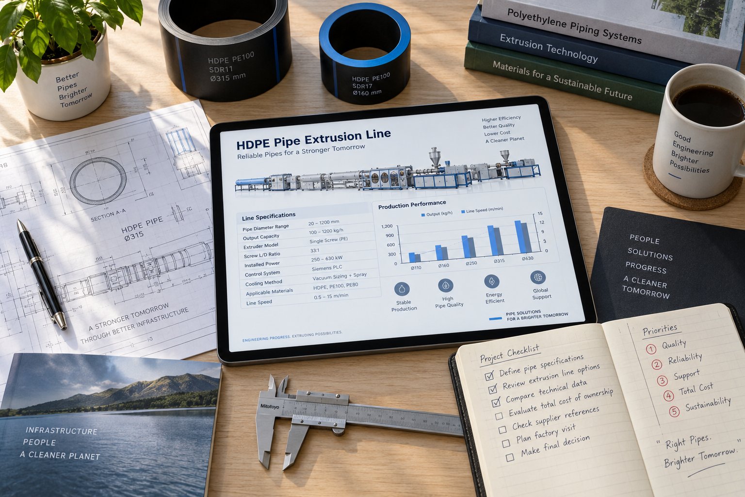
How to Choose the Right HDPE Pipe Making Machine
You've walked through the components, the extrusion process, the specification logic, the automation tiers, the application standards, the cost realities, and the technologies reshaping the industry. Every section pointed toward the same underlying truth: the right machine isn't the one with the most impressive spec sheet — it's the one whose configuration, capability, and support ecosystem align precisely with what you need to produce, at the quality you need to hit, for the price-per-meter that makes your business viable. This final section pulls those threads together into a practical framework for making that decision with confidence.
Matching Machine Configuration to Your Production Goals
Start with your end product, not the equipment catalog. What pipe diameters does your target market require? What pressure classes and standards must those pipes meet? What annual volume justifies the investment? These three questions immediately narrow the field.
If your business targets 20 mm to 110 mm irrigation and cable ducting pipes, a compact line with a 50 mm to 65 mm extruder, moderate automation, and a coiling system at the end covers the requirement without overspending on capacity you won't use. If you're bidding on municipal water supply contracts demanding 200 mm to 630 mm PE100 pipe certified to ISO 4427, you need a mid-range to large extruder with precise wall thickness control, ultrasonic gauging, and downstream equipment built for heavy, rigid pipe handling. Trying to stretch a small machine beyond its design envelope or buying oversized equipment for a niche product both lead to the same outcome — wasted capital and suboptimal production economics.
Output capacity deserves careful scrutiny. Remember that a manufacturer's stated kg/h figure is a ceiling under ideal conditions, and your actual meters-per-hour throughput depends entirely on the pipe diameter and wall thickness you're producing. Run the cross-sectional area calculation for your specific products, apply a realistic efficiency factor of 80% to 90%, and compare the result against your volume targets before committing.
Automation level is a strategic choice, not a luxury upgrade. A fully automatic hdpe pipe making machine costs more upfront but delivers lower per-meter costs, tighter tolerances, and reduced scrap at scale. A semi-automatic line offers a practical middle path for producers whose volumes don't yet justify full closed-loop control. Match the automation tier to your production volume, your labor market, and the standards your customers demand — not to what looks impressive in a showroom demonstration.
Downstream equipment matters just as much as the extruder itself. Cooling capacity limits your maximum line speed. Haul-off precision determines wall thickness consistency. Cutting accuracy affects end-squareness and fusion weld preparation. Evaluate these stations as seriously as you evaluate screw diameter and motor power, because a bottleneck anywhere in the chain throttles the entire line.
Building a Reliable Supply Chain for Long-Term Success
Selecting the right machine is the first decision, not the last one. Long-term hdpe pipe production line setup success depends on an ecosystem of support that extends far beyond the equipment itself.
Quality raw materials — certified PE80 or PE100 resin from reputable compounders — form the foundation. No machine compensates for inconsistent or substandard feedstock. Reliable additive suppliers for carbon black masterbatch and UV stabilizers ensure your formulation stays locked to specification batch after batch.
Trained operators transform equipment capability into actual production performance. Even fully automatic lines require personnel who understand process parameters, can interpret alarm conditions, and know when to intervene. Budget for initial training during commissioning and ongoing skill development as your team gains experience with different products and materials.
Proactive maintenance, as the previous section detailed, prevents the gradual quality erosion and emergency breakdowns that destroy profitability. A written maintenance schedule — covering screw and barrel measurement, heater band checks, vacuum pump service, and cooling system cleaning — keeps your line running at peak efficiency rather than slowly degrading toward failure.
Perhaps most critically, a dependable spare parts supply chain ensures that when wear components reach end of life, replacements arrive quickly and match your extruder's specifications precisely. For the screw and barrel in particular, sourcing matters enormously. Generic replacements with incorrect bore tolerances, inadequate nitriding depth, or mismatched metallurgy introduce the very quality problems you're trying to prevent. Specialist suppliers like NANHAIYA, which focuses specifically on custom and replacement single screw barrels for pipe extrusion and other plastic processing lines, can supply components engineered to match your extruder model and production requirements — an important advantage when restoring or upgrading performance on a line that has accumulated thousands of operating hours.
When you're evaluating machines and planning your hdpe pipe machine buyer guide checklist, prioritize these factors in order of their impact on long-term success:
- Component quality and durability — Verify the metallurgy and manufacturing quality of high-wear components, especially the screw, barrel, and die. These determine how long the machine sustains peak performance before requiring replacement.
- Spare parts availability and supplier reliability — Confirm that critical wear parts, electronics, and consumables are readily available from the OEM or qualified specialist suppliers. A machine without accessible replacement parts is a machine waiting for an extended, costly shutdown.
- Pipe diameter range and output capacity match — Ensure the extruder size, die tooling options, and downstream equipment align with your target product range and volume requirements, both current and projected.
- Automation level appropriate to your production scale — Select the control and measurement package that matches your volume, labor availability, and quality compliance targets without overinvesting or underequipping.
- Energy efficiency of drive systems and heating — Evaluate motor technology, barrel heating systems, and cooling configurations for their cumulative impact on per-kilogram energy costs over the equipment's full operating life.
- Standards compliance capability — Confirm that the machine's dimensional control precision, wall thickness tolerances, and marking systems meet the specific pipe standards required by your target markets.
- After-sales support and training — Assess the manufacturer's commissioning support, operator training programs, remote diagnostic capabilities, and responsiveness to technical inquiries.
- Installation requirements and site readiness — Factor in power supply infrastructure, cooling water systems, floor space, foundation specifications, and local building or environmental permits before finalizing the purchase.
Every item on this list connects back to a concept explored earlier in this guide — from the screw geometry discussion that informs component quality evaluation, to the automation comparison that frames your control system decision, to the total cost of ownership analysis that makes energy efficiency and spare parts planning non-negotiable priorities.
Choosing how to choose an hdpe pipe making machine ultimately comes down to one principle: treat the purchase as the beginning of a production partnership, not a one-time transaction. The machine, the materials, the people, the maintenance program, and the supply chain for critical components like screws and barrels all have to work together, year after year, to deliver compliant pipe at a cost that sustains your business. Get that ecosystem right, and the equipment pays for itself many times over. Get any single element wrong, and even the most impressive specification sheet won't prevent the problems that follow.
Frequently Asked Questions About HDPE Pipe Making Machines
1. What components make up a complete HDPE pipe making machine production line?
A complete HDPE pipe extrusion line consists of a hopper and gravimetric feeder for material dosing, a single-screw extruder with barrel and screw for melting and pressurizing resin, a drive motor and gearbox, a screen changer for melt filtration, a spiral mandrel die head that shapes the melt into a tubular profile, a vacuum calibration tank for sizing, spray cooling tanks for solidification, a caterpillar-style haul-off unit controlling wall thickness, an inline printer for marking, a planetary or chipless cutter, and a stacker or coiler for finished product handling. Each component is interdependent — a worn screw degrades melt quality that the die cannot correct, and a misaligned calibration sleeve introduces ovality the haul-off cannot fix.
2. How does the HDPE pipe extrusion process work step by step?
The process begins with PE resin (typically PE80 or PE100 grade) being fed into the extruder via a gravimetric dosing system along with additives like carbon black masterbatch. Inside the barrel, multiple heating zones and screw rotation generate frictional shear heat to melt the granules into a homogeneous fluid at 190-220 degrees Celsius. The pressurized melt is forced through a spiral mandrel die head, forming a continuous tubular profile. The soft tube then enters a vacuum calibration tank where negative pressure pulls it against a precision sleeve to set exact diameter and roundness. Multi-stage spray cooling solidifies the pipe, a servo-driven haul-off controls wall thickness by regulating pull speed, an inkjet printer applies identification markings, and a traveling cutter makes clean cuts at programmed lengths. Rigid pipes are stacked while smaller flexible pipes are wound onto coils.
3. What do screw diameter and L/D ratio mean on an HDPE pipe machine specification sheet?
Screw diameter is the primary determinant of output capacity because extrusion volume scales roughly with the square of the diameter. Smaller screws (45-65 mm) handle pipes from 16 mm to about 110 mm, mid-range screws (65-90 mm) cover 63-315 mm pipes, and large screws (90 mm+) produce pipes up to 1,200 mm. The L/D ratio (length-to-diameter) governs melt quality by determining how long the polymer stays inside the barrel. For HDPE pipe extrusion, ratios between 30:1 and 36:1 are standard. Values below 30:1 risk incomplete plasticization, while excessively high ratios increase energy use and thermal degradation risk. When comparing machines with the same screw diameter, a higher L/D ratio generally delivers better melt homogeneity.
4. How often should the screw and barrel be replaced on an HDPE pipe extruder?
Screw and barrel wear should be monitored by measuring barrel bore diameter and screw flight outer diameter every 3,000 to 5,000 operating hours. As clearance between the screw and barrel grows, melt slips backward instead of being pumped forward, reducing throughput and increasing discharge temperature. Replacement timing depends on resin type, production volume, and acceptable quality thresholds, but gradual signs like wall thickness drift, declining output at constant screw speed, and increased surface roughness signal that wear is reaching critical levels. When replacement is needed, sourcing from specialists like NANHAIYA — which provides custom single screw barrels engineered specifically for pipe extrusion — ensures correct metallurgy, bore tolerance, and heat treatment matched to continuous HDPE processing demands.
5. What is the difference between manual, semi-automatic, and fully automatic HDPE pipe production lines?
Manual lines rely on operators for temperature setting, visual quality checks, and manual cutting, requiring 4-5 workers per shift with variable output quality and scrap rates above 3-5%. Semi-automatic lines introduce PLC-based temperature control and automated cutting, reducing crew to 2-3 operators with improved consistency. Fully automatic lines integrate PLC/HMI control panels, ultrasonic wall thickness measurement with closed-loop correction, gravimetric dosing, servo-driven haul-offs, and automated stacking, needing just 1-2 operators with scrap rates under 1-2%. The choice depends on production volume, labor costs, and standards requirements — fully automatic lines cost more upfront but deliver significantly lower per-meter production costs at scale and are essential for meeting tight dimensional tolerances in standards like ISO 4427.
Written by
Nanhaiya Technical Team
Zhoushan Nanhaiya Plastic Machinery Co., Ltd.
The Nanhaiya technical team supports screw and barrel manufacturing projects through application review, technical communication, custom manufacturing coordination, and production and quality control.
Discuss Your Application
Related Articles
More insights on screw barrel technology and plastics processing.
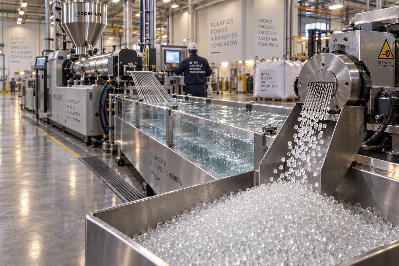
Pick the Wrong Plastic Pelletizing Line and You Pay Twice
Oct 14, 2026
Learn how to spec the right plastic pelletizing line for your resin, throughput, and budget. Covers strand, underwater, and air-cooled systems plus ROI planning.
Read Article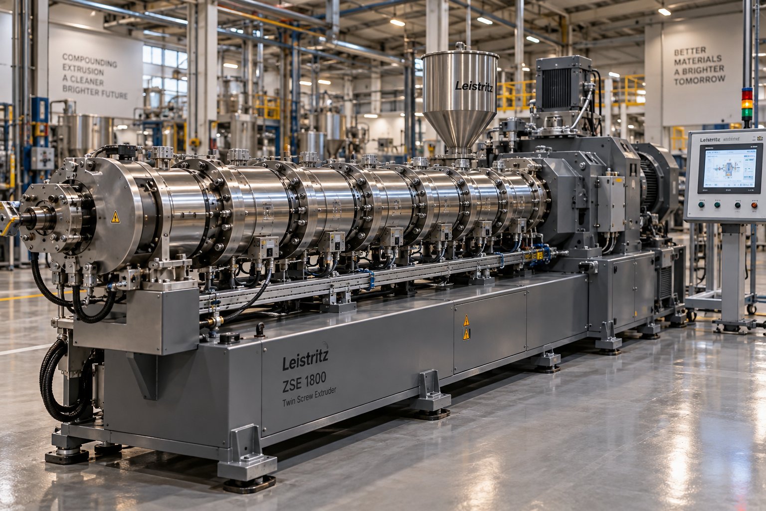
Co Rotating Twin Screw Extruder Manufacturer: Beyond The Brochure
Oct 13, 2026
Learn how to evaluate a co rotating twin screw extruder manufacturer using specs, TCO analysis, red flags, and a step-by-step buyer framework.
Read Article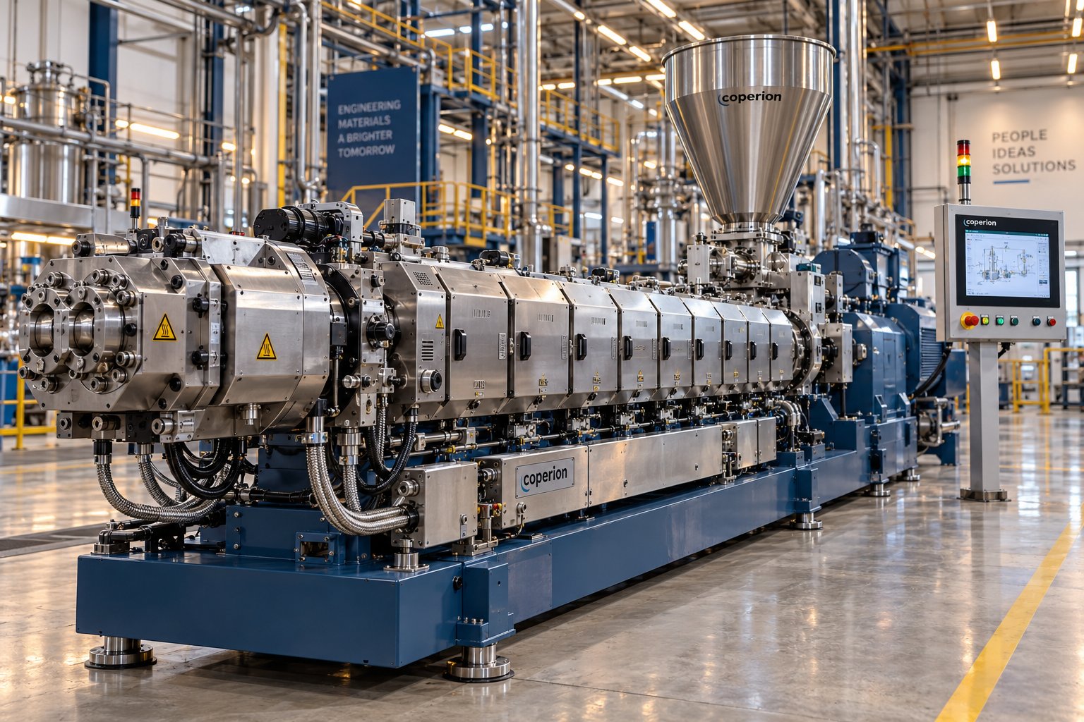
Stop Overpaying: How To Read Any Parallel Twin Screw Extruder Price
Oct 13, 2026
Learn what drives parallel twin screw extruder price from lab to production scale. Compare specs, metallurgy, manufacturer tiers, and total cost of ownership.
Read ArticleLooking for something else?
Search by material, symptom or product and jump straight to the relevant page.
These are navigation suggestions based on keyword matching — not a quotation, not a delivery commitment, and not a substitute for engineering review. Final specification is confirmed by our engineers against your drawings and processed material.
Need help with screw barrel selection?
Share your machine model, processed material and application. Our team can help with pricing and technical support.