

What Is an HDPE Pipe Extrusion Line and Why It Matters
Imagine a single production system that takes tiny plastic pellets at one end and delivers perfectly formed, pressure-rated pipes at the other — all in one continuous motion. That is exactly what an HDPE pipe extrusion line does, and it sits at the heart of nearly every modern pipe manufacturing facility on the planet.
Defining the HDPE Pipe Extrusion Line
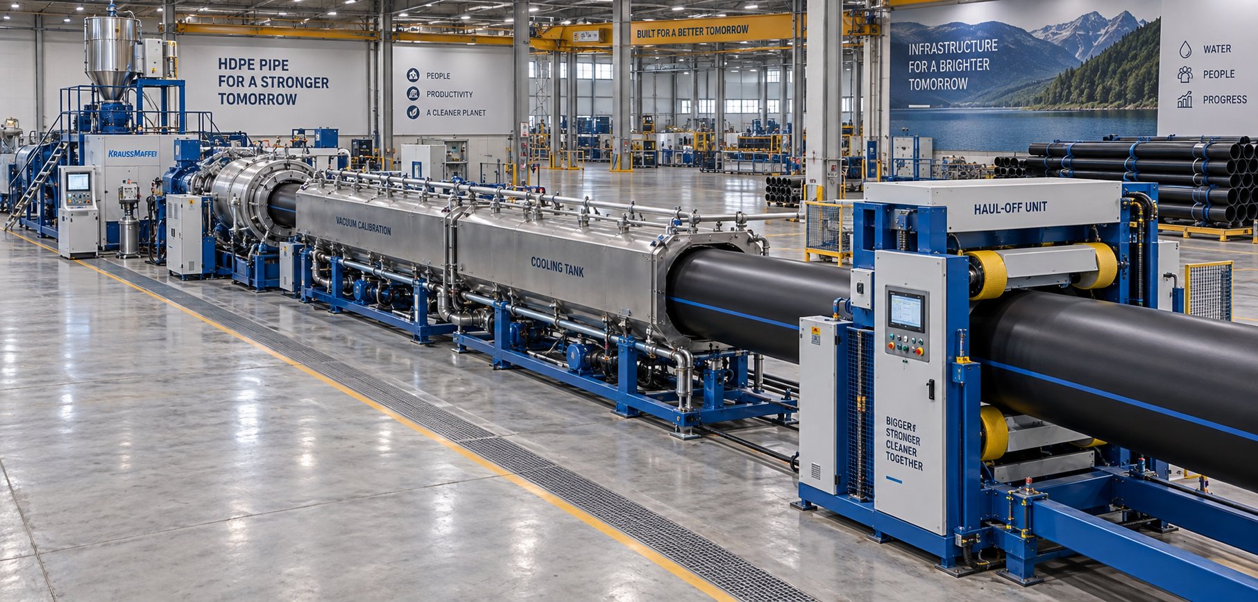
An HDPE pipe extrusion line is an integrated production system that converts raw high-density polyethylene resin into finished pipes through continuous melt processing, encompassing material feeding, plasticization, shaping, sizing, cooling, cutting, and stacking in a single coordinated workflow.
In simpler terms, you're looking at a chain of specialized machines arranged in sequence on a factory floor. Each unit performs a specific task — melting, shaping, cooling, pulling, cutting — and hands the product off to the next stage without interruption. The result is a seamless pipe extrusion process capable of running around the clock with minimal human intervention.
What makes this system distinct from other polymer processing methods is the word "continuous." Unlike injection molding, which produces individual parts in cycles, pipe extrusion never stops mid-run. Resin feeds in constantly, and finished pipe emerges at the downstream end at a steady rate, often measured in meters per minute.
Why HDPE Pipe Production Matters for Modern Infrastructure
HDPE pipes are quietly reshaping the infrastructure beneath our feet. The global HDPE pipes market reached USD 21.82 billion in 2024 and is projected to climb to USD 28.46 billion by 2029, growing at a 5.5% CAGR. Those numbers reflect a straightforward reality: municipalities, utilities, and industrial operators increasingly rely on HDPE for applications where metal and concrete fall short.
Consider the range of critical roles these pipes fill:
- Water supply — potable water networks depend on HDPE's corrosion resistance and leak-free fused joints.
- Gas distribution — flexibility and impact resistance make HDPE the default choice for natural gas lines in seismically active regions.
- Drainage and sewage — smooth internal bore minimizes friction loss and resists chemical attack from aggressive effluents.
- Industrial fluid transport — mining slurry lines, chemical transfer systems, and cooling circuits all benefit from HDPE's durability and 50-to-100-year service life.
Every one of these pipes begins its life on a pipe extrusion line. The precision, consistency, and capability of that line directly determine whether the finished pipe meets the demanding standards these applications require.
What This Guide Covers
Most resources on this topic stop at a surface-level overview — a paragraph on extrusion here, a mention of cooling there. This guide takes a different approach. You'll walk through the complete upstream-to-downstream production ecosystem, starting with raw material handling and feeding, moving through plasticization inside the extruder barrel, and continuing into die head shaping, vacuum sizing, multi-stage cooling, haul-off, cutting, and final finishing.
Along the way, you'll find detailed breakdowns of screw and barrel specifications, die head design principles, vacuum calibration mechanics, line configurations by pipe diameter range, a troubleshooting reference for common extrusion defects, and the international standards every producer must satisfy. Whether you're a process engineer deepening your technical knowledge or an equipment buyer evaluating your next HDPE pipe extrusion line, every section is built to give you actionable clarity — not sales pitches.
The logical starting point? Understanding exactly what each component in the line does and how it connects to the next.
Every Component of the HDPE Pipe Extrusion Machine Explained
Each station in a production line has a single job — and if it fails, every station after it inherits the problem. That cause-and-effect chain is why a thorough component-by-component understanding matters far more than a vague overview. Below, you'll find every major unit in the sequence it actually occupies on the factory floor, from the moment resin pellets leave storage to the instant a finished pipe rolls off the stacker.
Material Handling and Feeding System
Before any melting happens, raw HDPE pellets need to reach the extruder in a consistent, contaminant-free stream. This is the job of the material handling system, and it includes three core elements:
- Hopper — a funnel-shaped reservoir mounted directly above the extruder throat. It holds a working volume of resin and gravity-feeds pellets downward into the barrel.
- Gravimetric feeder — positioned between the hopper and the extruder inlet, this unit meters pellets by weight rather than volume. It continuously weighs the material flow, compensating automatically for density variations and ensuring a precise, repeatable feed rate. Color masterbatch or additive dosing typically integrates here.
- Dryer — although HDPE absorbs very little moisture compared to nylon or PET, residual surface moisture can still cause bubbles or voids in the finished pipe. A dehumidifying dryer upstream of the hopper removes that risk before pellets ever enter the barrel.
Think of this stage as the quality gatekeeper. If the feed rate fluctuates or moisture slips through, you'll see the consequences — uneven wall thickness, surface imperfections — kilometers down the cooling line.
The Single-Screw Extruder Unit
The extruder is the powerhouse of any HDPE pipe extrusion machine. It accepts solid pellets and delivers a uniform, pressurized melt to the die head. Four subcomponents work together to make that happen:
- Motor — provides the rotational energy that drives the screw, typically an AC servo or variable-frequency motor offering precise speed control.
- Gearbox — reduces motor speed while multiplying torque, allowing the screw to generate the high pressures needed to push viscous molten HDPE forward.
- Barrel — a thick-walled, heated steel cylinder lined with wear-resistant material. It houses the screw and features multiple temperature-controlled zones (heating and cooling) that govern melting behavior along the barrel length.
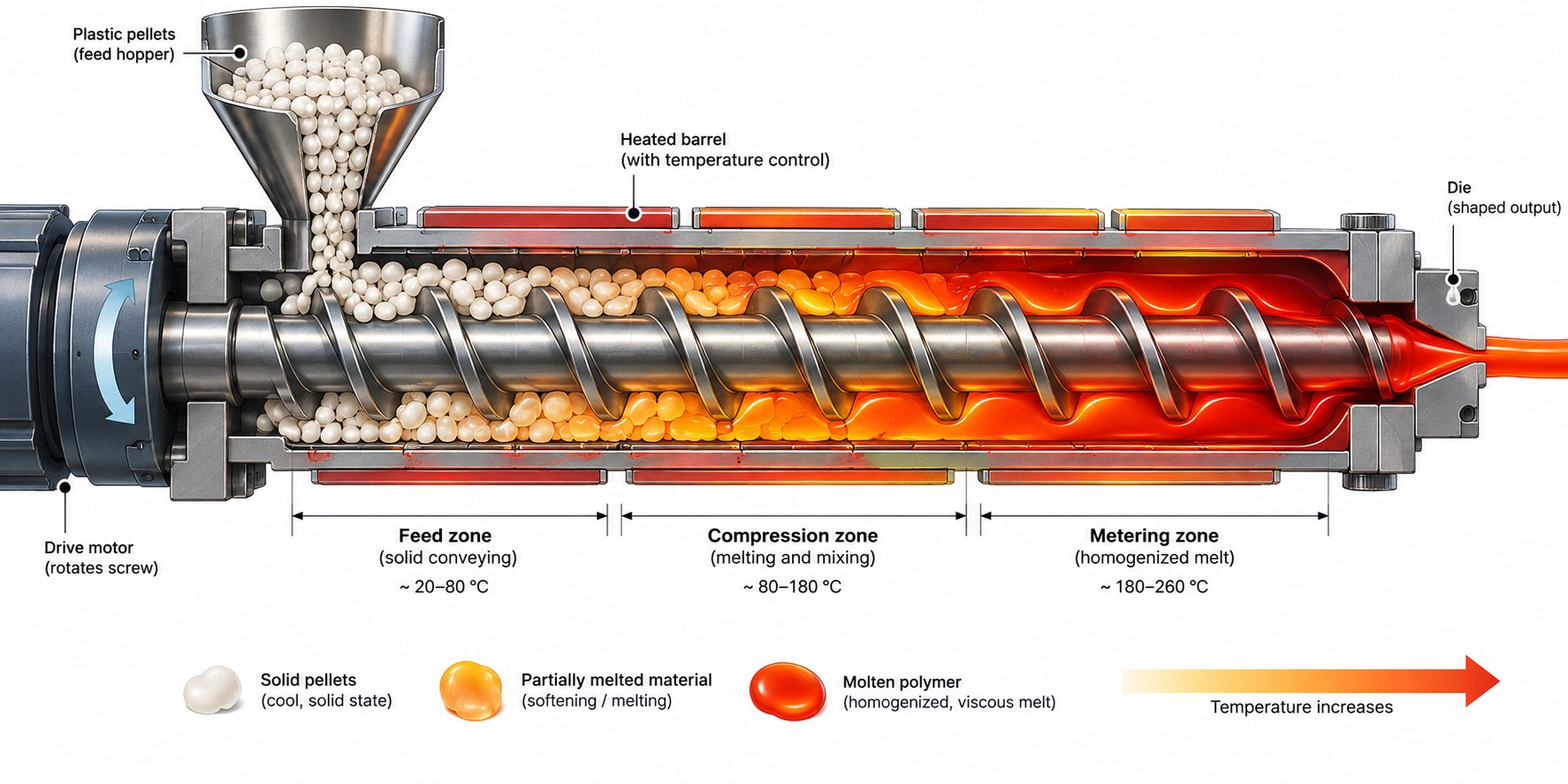
- Screw — the single rotating element inside the barrel, designed with distinct feed, compression, and metering zones. As it turns, it conveys pellets forward, generates frictional and conducted heat to melt them, compresses the melt to remove air, and meters a homogeneous flow toward the outlet.
Between the extruder outlet and the die head, most lines include a screen changer — a filter assembly that traps contaminants and degraded polymer particles — and sometimes a melt pump that stabilizes pressure pulsations for smoother output. These two elements are easy to overlook, but they directly influence the surface quality and dimensional consistency of the finished pipe.
Downstream Equipment From Die Head to Stacker
Once the melt leaves the extruder, it enters the downstream section — the series of stations that transform a hot, formless polymer stream into a rigid, dimensionally accurate pipe ready for shipment. Here's how each unit contributes:
- Extrusion die head — constructed from high-strength alloy steel with optimized flow channels, the die shapes the melt into an annular (ring-shaped) cross-section. Temperature control and flow channel geometry determine wall uniformity and surface smoothness.
- Vacuum calibration tank — the freshly extruded pipe, still soft and pliable, enters this water-filled tank where vacuum pressure pulls its outer wall against a precision calibration sleeve. This locks in the pipe's outer diameter and roundness.
- Spray cooling tanks — additional cooling stages use water spray or immersion to remove residual heat from the pipe wall, solidifying the crystalline structure and preventing downstream deformation.
- Haul-off unit — a caterpillar-style dual-belt traction system that grips the cooled pipe and pulls it through the entire downstream line at a precisely synchronized speed. Wall thickness depends directly on the ratio between extruder output and haul-off speed.
- Cutting unit — a planetary saw or chip-free cutter that travels with the pipe and cuts it to programmed lengths without stopping the line. The blade orbits around the pipe to produce clean, burr-free ends.
- Stacker or coiler — large-diameter rigid pipes are stacked or palletized for transport, while smaller-diameter flexible pipes are wound onto coils by an automatic winder for easier handling.
The table below consolidates every component into a single reference, linking each unit's function to the next stage in the PE pipe extrusion machine sequence:
| Component | Function | Key Operating Principle | Connection to Next Stage |
|---|---|---|---|
| Hopper | Stores and gravity-feeds resin pellets | Gravity flow with level sensors | Supplies pellets to the gravimetric feeder |
| Gravimetric Feeder | Meters pellets by weight for precise dosing | Continuous loss-in-weight measurement | Delivers consistent feed rate to the extruder inlet |
| Dryer | Removes surface moisture from pellets | Heated desiccant or dehumidified air circulation | Feeds dry pellets into hopper or directly to feeder |
| Single-Screw Extruder | Melts, compresses, and homogenizes HDPE | Rotating screw generates shear heat and pressure inside a heated barrel | Pushes uniform melt through the screen changer |
| Screen Changer | Filters contaminants and degraded particles | Mesh screens trap impurities; slide or bolt design allows screen replacement | Passes clean melt to the melt pump or die head |
| Melt Pump (optional) | Stabilizes melt pressure for uniform output | Positive-displacement gear pump smooths pressure fluctuations | Delivers steady-pressure melt to the die head |
| Extrusion Die Head | Shapes melt into annular pipe profile | Spiral or radial flow channels distribute melt evenly around a mandrel | Extruded hot pipe enters the vacuum calibration tank |
| Vacuum Calibration Tank | Sets outer diameter and roundness | Vacuum pulls soft pipe wall against a precision metal sleeve while water cools the surface | Partially cooled pipe moves into spray cooling tanks |
| Spray Cooling Tanks | Removes residual heat to solidify pipe structure | Water spray or immersion extracts heat through the pipe wall | Rigid, cooled pipe enters the haul-off unit |
| Haul-Off Unit | Pulls pipe at constant, synchronized speed | Caterpillar dual-belt traction with servo-controlled drive | Feeds pipe at steady rate into the cutting unit |
| Planetary / Chip-Free Saw | Cuts pipe to programmed length on-the-fly | Blade orbits the pipe, traveling with it to cut without stopping the line | Cut pipe transfers to stacker or coiler |
| Stacker / Coiler | Organizes finished pipe for storage and shipping | Stacker palletizes rigid pipes; coiler winds flexible pipes onto reels | End of production line — finished product ready for dispatch |
Every component in this sequence is interdependent. A worn screw reduces melt quality, which the die head cannot correct. A misaligned calibration sleeve introduces ovality that the haul-off cannot fix. Understanding each unit's role — and its limits — is what separates a smooth-running HDPE extruder machine from one plagued by recurring defects. The real question, though, is what actually happens to the resin inside these machines at each stage — and how specific process settings determine whether you produce a flawless pipe or a reject.
How the Pipe Extrusion Process Works Step by Step
Knowing what each machine does is one thing. Understanding what actually happens to the polymer as it travels through those machines — and why specific settings at each station make or break pipe quality — is where real process mastery begins. So how is HDPE manufactured into a finished pipe? The answer lies in nine tightly linked stages, each with parameters that directly influence the product rolling off the line.
From Resin Pellet to Molten Polymer
The pipe extrusion process begins well before the extruder screw starts turning. Raw HDPE pellets first pass through drying and blending, where residual surface moisture is removed and color masterbatch or stabilizer additives are dosed at precise weight ratios by the gravimetric feeder. Skipping or shortcutting this step invites bubbles and surface blemishes that no downstream adjustment can erase.
Once inside the barrel, the pellets encounter three functionally distinct screw zones. In the feed zone, solid granules are conveyed forward and begin compacting. The compression zone applies increasing pressure as channel depth decreases, generating frictional shear heat that melts the resin — barrel temperatures here typically ramp from 180 to 220 °C. Finally, the metering zone stabilizes at around 210–230 °C, delivering a uniform, fully plasticized melt at consistent pressure and flow rate. If screw speed is too high, residence time drops and plasticization suffers; too low, and throughput stalls. Most HDPE pipe lines operate between 20 and 60 rpm, balanced against output targets.
Before reaching the die, the melt passes through a screen changer that filters out contaminants and degraded particles, and in some configurations a melt pump that irons out pressure pulsations. These filtration and homogenization steps directly govern surface finish quality — clean, stable melt flow means a smoother pipe wall.
Shaping, Sizing, and Cooling the Pipe
The transformation from shapeless melt to recognizable pipe happens across three rapid-fire stages. Here is the complete sequence of the extrusion of pipes from start to finish:
- Material drying and blending — pellets are dried and mixed with masterbatch at controlled ratios to eliminate moisture and ensure uniform color and additive distribution.
- Plasticization — the extruder screw conveys, melts, and homogenizes resin through feed, compression, and metering zones under tightly controlled barrel temperatures.
- Melt homogenization and filtration — screen changers remove contaminants while optional melt pumps stabilize pressure for consistent output.
- Annular die shaping — the molten polymer is distributed evenly around a mandrel and extruded through an annular gap, forming the initial pipe profile. Die temperature is typically held slightly below the metering zone — around 200–220 °C — to prevent thermal degradation at the exit.
- Vacuum sizing — the still-soft pipe enters a calibration tank where vacuum pressure pulls its outer surface against a precision metal sleeve, locking in outer diameter and roundness. Vacuum level is the primary control variable here: too little and the pipe sags, too much and the wall distorts.
- Controlled cooling — spray tanks or immersion baths extract heat progressively, allowing HDPE's semi-crystalline structure to develop properly. Cooling water temperature matters more than most operators realize — excessively cold water freezes the outer skin while the core remains molten, creating residual stress that weakens long-term performance.
- Haul-off at constant speed — caterpillar belts grip the solidified pipe and pull it through the line at a speed carefully synchronized to extruder output. The haul-off speed directly controls wall thickness: pulling faster stretches the wall thinner, while pulling slower allows it to build up.
- Cutting to length — a planetary saw or chip-free cutter travels with the moving pipe and cuts it at programmed intervals, producing clean ends without halting production.
- Downstream finishing — the cut pipe receives inkjet printing (size, standard, production date), passes through any final visual or dimensional inspection station, and transfers to a stacker or coiler for packaging.
Downstream Finishing and Quality Inspection
What separates a well-run line from a problematic one isn't any single parameter — it's how all parameters interact. Consider a practical example: you increase screw speed to boost throughput, but forget to adjust haul-off speed proportionally. The result? Thicker walls than specified, wasted material, and pipes that fail dimensional checks. Or imagine raising cooling water temperature to reduce energy costs — the slower crystallization rate may improve surface gloss, but it can also reduce the pipe's long-term creep resistance.
The table below maps the most influential process settings to the pipe quality attributes they control:
| Process Parameter | Primary Quality Attribute Affected | What Happens If Too High | What Happens If Too Low |
|---|---|---|---|
| Melt temperature | Surface finish, mechanical strength | Thermal degradation, discoloration, reduced strength | Incomplete plasticization, rough surface, poor weld lines |
| Screw speed | Throughput, melt homogeneity | Insufficient residence time, poor plasticization | Low output, potential melt stagnation |
| Vacuum level (sizing tank) | Outer diameter accuracy, roundness | Wall distortion, surface marks from excessive suction | Undersized OD, sagging, ovality |
| Cooling water temperature | Crystallinity, residual stress, surface quality | Slow crystallization, reduced stiffness | Rapid skin freezing, internal stress, potential warping |
| Haul-off speed | Wall thickness, dimensional stability | Stretched, thinner walls than target | Thicker walls, material waste, possible buckling |
Every entry in that table traces back to a specific component in the line. Melt temperature depends on barrel heaters and screw design. Vacuum level is set at the calibration tank. Haul-off speed is controlled by the traction unit's servo drive. This tight coupling between equipment and outcome is precisely why understanding the hardware specifications behind each stage — especially the screw and barrel that initiate the entire melt quality chain — becomes so critical.
Screw and Barrel Specifications That Drive HDPE Extrusion Performance
Melt quality sits at the very top of the cause-and-effect chain in any HDPE pipe extrusion line — and that quality is determined almost entirely by two components: the screw and the barrel. Every process parameter discussed so far — melt temperature, homogeneity, pressure stability — originates inside this pair. Yet most technical guides gloss over screw and barrel specifications as if they were interchangeable commodity parts. They are not. The dimensions, geometry, and metallurgy of your screw and barrel dictate throughput capacity, energy consumption, melt consistency, and ultimately whether your finished pipe meets specification or ends up as scrap.
Understanding Screw L/D Ratio for HDPE Processing
You'll encounter one specification more than any other when evaluating an hdpe extrusion machine: the L/D ratio. This is simply the screw's functional length divided by its diameter. A screw that measures 2,640 mm long with an 80 mm diameter has an L/D of 33:1.
Why does this ratio matter so much? Because it defines how long the resin stays inside the barrel — and how much mechanical and thermal energy it absorbs along the way. A longer screw relative to its diameter gives the polymer more time to melt, mix, and homogenize before reaching the die. For HDPE specifically, this is critical. As a semi-crystalline polymer with a relatively sharp melting point, HDPE demands thorough, uniform plasticization. Partially melted crystallites passing through the die create rough surfaces, weak weld lines, and dimensional instability.
Industry practice for HDPE pipe extrusion settles on an L/D ratio of 30:1 to 33:1. This range provides enough barrel length for complete melting and homogenization without the thermal degradation risks that come with excessively long residence times. Reference data on PE processing confirms that general PE/PP pelletizing and extrusion typically calls for L/D ratios between 28:1 and 33:1, with higher ratios favoring applications where melt uniformity and mixing intensity are paramount — exactly the conditions pipe production demands.
Sounds like a narrow window? It is, intentionally. Drop below 28:1 and you risk pushing incompletely melted resin into the die head. Exceed 36:1 and the extended heat exposure can degrade HDPE's molecular chains, reducing the pipe's long-term stress crack resistance — the very property that makes it valuable for pressurized infrastructure.
How Screw Diameter Determines Output Capacity
If L/D ratio governs melt quality, screw diameter governs quantity. A larger screw diameter means a larger channel cross-section, which translates directly into higher volumetric throughput per revolution. This is why you'll see small-diameter extruders on pilot lines and large-diameter machines driving high-volume production floors.
For an hdpe extruder dedicated to pipe production, common screw diameters range from 45 mm for small-diameter tubing up to 120 mm and beyond for heavy-wall, large-bore pipes. Each step up in screw size corresponds to a roughly proportional increase in output capacity and motor power requirements.
The table below maps common screw diameters to their typical output ranges and the pipe diameter ranges they generally serve. These figures reflect widely referenced industry sizing guidelines and may vary based on specific screw design, resin grade, and operating speed:
| Screw Diameter | Typical L/D Ratio | Approximate Output Range | Suitable Pipe Diameter Range |
|---|---|---|---|
| 45 mm | 30:1 – 33:1 | 30 – 80 kg/h | 16 – 63 mm |
| 65 mm | 30:1 – 33:1 | 80 – 200 kg/h | 50 – 160 mm |
| 75 mm | 30:1 – 33:1 | 200 – 350 kg/h | 110 – 315 mm |
| 90 mm | 30:1 – 33:1 | 250 – 450 kg/h | 160 – 630 mm |
| 120 mm | 30:1 – 33:1 | 450 – 900 kg/h | 315 – 1200 mm |
Notice the overlap in pipe diameter ranges across adjacent screw sizes. That's because achievable pipe size depends not only on extruder output but also on wall thickness, line speed, and die head configuration. A 90 mm screw can produce a 200 mm pipe at high wall thickness or a 630 mm pipe at minimum wall — the material volume per meter of pipe changes dramatically with diameter and SDR rating.
Barrel Construction and Wear Resistance
The barrel does far more than just house the screw. It serves as the primary heat transfer surface, the pressure containment vessel, and the wear surface that endures constant abrasion from glass-filled or mineral-loaded compounds. Even with neat HDPE, thousands of operating hours take a toll.
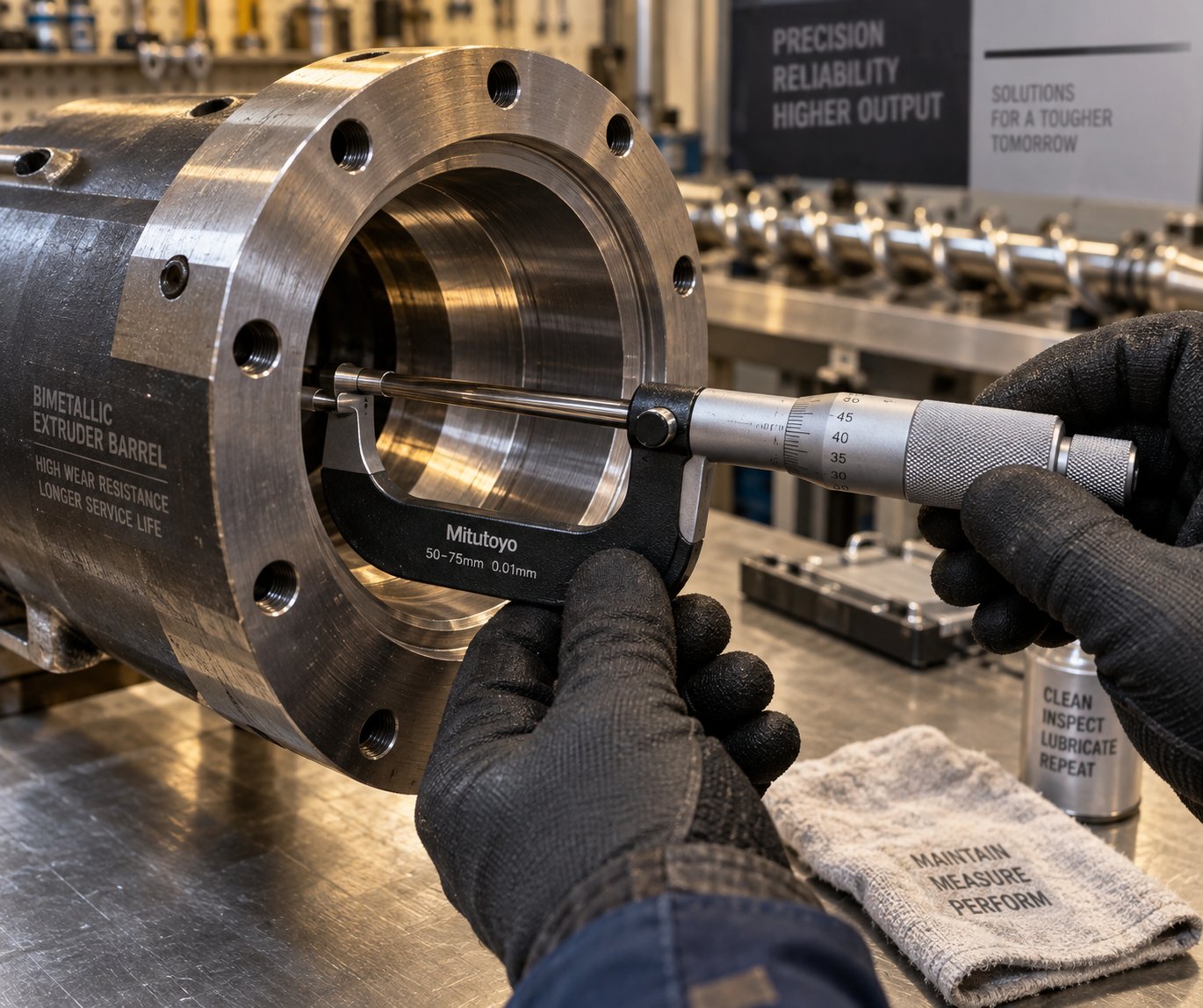
High-performance barrels for hdpe extrusion use a bimetallic lining — a centrifugally cast wear-resistant alloy (typically iron-boron or nickel-based) bonded to the inner bore of a structural steel outer shell. This composite construction delivers the hardness needed to resist abrasive wear on the inside while maintaining the toughness and machinability required for the barrel body itself. Standard nitrided barrels work for short runs or non-abrasive materials, but any serious pipe production facility running continuous shifts will benefit from bimetallic construction.
Equally important is the heating and cooling zone design. A typical pipe extrusion barrel features four to six independently controlled thermal zones, each equipped with ceramic band heaters and air or water cooling channels. This zoned architecture allows operators to establish a precise temperature profile — lower in the feed zone to prevent premature melting and bridging, progressively higher through the compression zone, and tightly regulated in the metering zone to deliver a stable melt temperature to the die. If any zone drifts out of range, you'll see it immediately in wall thickness variation or surface quality.
Over time, the bore diameter of even a bimetallic barrel gradually increases due to wear, widening the clearance between screw flight and barrel wall. That growing gap reduces pumping efficiency, increases energy consumption, and degrades melt homogeneity — all of which silently erode pipe quality and throughput. This is why the screw and barrel deserve more maintenance attention than any other component on the line.
For facilities facing these wear-related challenges or planning new line builds, sourcing precision-engineered replacement barrels is essential. NANHAIYA's single screw barrel program offers custom and replacement barrels designed specifically for pipe, film, sheet, pelletizing, recycling, and general-purpose extrusion lines. Their application-specific engineering means the barrel metallurgy, bore tolerances, and zone layout are matched to the demands of HDPE pipe production — not adapted from a one-size-fits-all catalog. For readers comparing screw and barrel specifications across suppliers, NANHAIYA's product page provides a practical reference point for understanding what purpose-built barrel construction looks like in practice.
Getting the screw and barrel right establishes the foundation for melt quality. But melt quality alone doesn't guarantee a dimensionally accurate pipe — that responsibility falls to two downstream systems that most resources barely explain: the die head and the vacuum calibration tank.
Die Head Design and Vacuum Calibration for Extruded HDPE Pipe
A perfectly plasticized melt is only half the battle. If the die head distributes that melt unevenly — or the calibration tank fails to lock in the pipe's geometry — you'll produce scrap regardless of how well the extruder performed. These two systems operate in tight partnership: the die head shapes the melt into an annular profile, and the vacuum calibration tank freezes that profile into a dimensionally stable pipe. Yet most technical references treat both as black boxes. Here's what actually happens inside them — and why the engineering details matter for every meter of extruded polyethylene that leaves your line.
Spiral Mandrel vs Basket Die Head Designs
When molten HDPE exits the extruder, it flows as a single pressurized stream. The die head's job is to transform that stream into a uniform, hollow cylinder — and the way it distributes melt around the annular gap determines whether the finished pipe has consistent wall thickness or problematic thin spots.
Two fundamental architectures handle this distribution differently:
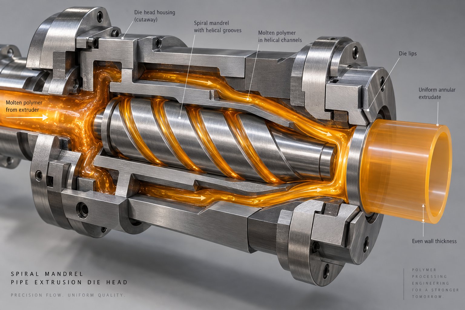
Spiral mandrel die heads are the dominant design in modern polyethylene extrusion. The incoming melt stream splits into multiple feed ports at the die inlet, each channeling polymer into a helical groove carved into the surface of a central mandrel. As these spiral channels progress along the mandrel's length, their depth gradually decreases while the gap between the mandrel and the outer die body simultaneously increases. This geometry forces polymer to "leak" out of the spiral grooves and merge into a continuous annular flow. The overlapping leakage from adjacent spirals blends together, effectively eliminating weld lines and creating a remarkably uniform melt distribution around the full circumference.
Research into spiral mandrel die mechanics confirms that this design achieves uniform thickness, velocity, and temperature distribution of the polymer melt at the die exit — advantages that directly translate into consistent wall thickness in the finished pipe. The same research highlights that mandrel geometry parameters — specifically the initial depth of spiral grooves, the mandrel's taper angle (determined by end radius), and the helix angle — have a significant influence on both flow behavior and the mechanical stress state of the die body. A deeper initial groove, for example, accommodates higher throughput but increases pressure-induced deformation at the die orifice. Adjusting helix angle affects how evenly the melt redistributes between grooves, with angles in the range of 12 to 16 degrees generally reducing peak stress in the die structure.
Imagine a barber pole pattern etched into the mandrel surface — that's essentially the spiral channel layout. As polymer fills these grooves and gradually escapes into the annular gap, it undergoes a natural blending that no flat-channel geometry can replicate. The result is a pipe wall with no discernible weld lines and minimal circumferential thickness variation, even at high production speeds.
Basket (or screen-pack) die heads use a different approach. Instead of spiral channels, they force melt through a cylindrical screen or perforated sleeve surrounding the mandrel. The melt passes through hundreds of small holes, then re-merges into an annular flow downstream. Basket dies are simpler to manufacture, less expensive, and easier to disassemble for cleaning. However, each perforation creates a micro-weld line where separate melt streams rejoin — and while these lines are typically fused under subsequent pressure in the die land, they can remain as weak points under extreme service conditions. Basket designs see use primarily in lower-pressure drainage pipe or applications where absolute wall uniformity is less critical.
For pressurized water and gas pipe production — the core applications of extruded HDPE — the spiral mandrel design remains the clear choice. Its ability to produce weld-line-free pipe with tight wall thickness tolerance makes it indispensable for meeting the standards these applications demand.
One practical detail worth noting: die gap adjustment at the die exit controls the pipe's final wall thickness and can compensate for minor flow imbalances. Most modern die heads feature adjustable centering bolts that allow operators to shift the die ring relative to the mandrel tip, fine-tuning the annular gap around its circumference. This adjustment is typically performed during startup and checked whenever a pipe dimension change is made.
How Vacuum Calibration Controls Pipe Dimensions
The instant the hot pipe profile exits the die, it faces a race against gravity and thermal contraction. Without immediate stabilization, the soft, amorphous tube would sag under its own weight, shrink unevenly as it cools, and lose any dimensional accuracy the die head established. Technical reporting on vacuum calibration systems notes that an uncontrolled melt can experience dimensional variance exceeding 15% without immediate sizing intervention.
Vacuum calibration solves this by creating a controlled pressure differential. Here's the mechanism in straightforward terms: the pipe enters a sealed, water-filled stainless steel tank where the air pressure has been reduced below atmospheric level. Because the inside of the pipe remains at atmospheric pressure (air enters through the mandrel of the die head), the higher internal pressure pushes the still-soft outer wall outward against a precision-machined calibration sleeve. This sleeve — typically manufactured from brass or stainless steel with a chrome-plated interior — is machined to the exact target outer diameter of the pipe, with tolerances often within ±0.02 mm.
The pipe's outer surface makes contact with the sleeve and begins to cool rapidly against the metal surface, forming a solidified "skin" that locks in the diameter. Water sprayed around the sleeve and within the tank accelerates this heat extraction. The combination of vacuum-driven expansion and rapid surface cooling is what gives the finished pipe its dimensional accuracy and roundness.
When calibration goes wrong, the symptoms are immediate and costly. Insufficient vacuum allows the pipe to pull away from the sleeve, producing undersized outer diameters and visible ovality. Excessive vacuum can press the wall too aggressively against the sleeve, creating surface drag marks or even collapsing the pipe if the internal air pressure is inadequate. Uneven cooling within the tank — caused by clogged spray nozzles or inconsistent water flow — solidifies one side of the pipe faster than the other, introducing residual stress and dimensional instability that may not show up until the pipe is under pressure in the field.
The key calibration parameters that operators must control include:
- Vacuum level — typically maintained between 0.02 and 0.06 MPa of negative pressure. The exact setting depends on pipe diameter, wall thickness, and resin melt strength. Larger-diameter, thinner-wall pipes generally require higher vacuum to counteract gravitational sagging.
- Water temperature — cooling water in the calibration tank is usually held between 15 and 20 °C for HDPE. This range balances rapid enough cooling to stabilize dimensions against the risk of quenching the surface too aggressively, which can induce internal stress.
- Sleeve material and surface finish — brass sleeves offer excellent thermal conductivity for fast heat extraction, while stainless steel sleeves with chrome plating provide superior wear resistance and longer service life. The interior surface must be smooth and free of burrs to prevent scoring the pipe surface.
- Sleeve length — a longer sleeve provides more contact time between the pipe surface and the cooling metal, allowing a thicker solidified skin to form before the pipe exits into the open spray zone. For large-diameter, thick-wall pipes, longer sleeves are essential to prevent the pipe from deforming once it loses the sleeve's mechanical support.
Advanced calibration tanks also incorporate automated vacuum regulation valves that respond to pressure fluctuations detected by digital transducers. If vacuum deviates by even a small margin, the control system adjusts pump speed to stabilize the differential — a feature that becomes increasingly important at higher line speeds where any fluctuation translates into measurable diameter ripples along the pipe length.
The Role of Cooling Water Temperature in Crystallization
Cooling water temperature deserves special attention because it doesn't just affect dimensional accuracy — it fundamentally shapes the pipe's internal structure and long-term mechanical performance. HDPE is a semi-crystalline polymer, and the rate at which it cools from its molten state determines how much crystallinity develops in the final product.
Cool the pipe too quickly with very cold water, and the outer layer solidifies into a highly stressed skin while the core remains molten. As the inner material eventually solidifies and contracts, it pulls against the already-rigid outer layer, creating residual tensile stress on the surface and compressive stress in the core. Over years of service under internal pressure, these locked-in stresses accelerate slow crack growth — the primary long-term failure mode for HDPE pressure pipe.
Cool the pipe too slowly with warm water, and the opposite problem emerges. The outer skin remains soft longer, making it vulnerable to deformation from haul-off contact pressure or its own weight as it spans between support rollers. The pipe may leave the line looking dimensionally correct but with lower crystallinity and reduced stiffness, leading to higher creep rates under sustained pressure loading.
The practical sweet spot for polyethylene extrusion falls in the 15–20 °C range for the calibration tank, with slightly warmer water (20–25 °C) acceptable in later spray cooling stages where the pipe structure has already partially solidified. Some producers implement a graduated cooling profile — colder water in the first spray zone, progressively warmer in subsequent zones — to manage the crystallization gradient through the pipe wall and minimize residual stress. This approach adds complexity to the water management system but pays dividends in long-term pipe performance, particularly for gas distribution mains and high-pressure water applications where slow crack growth resistance is a contractual requirement.
The interplay between die head precision and calibration control ultimately defines the dimensional envelope your line can consistently hold. Those capabilities become even more critical when you scale production across different pipe diameter ranges — where equipment configurations shift dramatically from one size tier to the next.
Line Configurations Compared by Pipe Diameter Range
A PE pipe extrusion line producing 32 mm irrigation tubing looks nothing like one turning out 1200 mm water mains. The extruder grows larger, the cooling section stretches longer, the haul-off becomes heavier, and the cutting method changes entirely. Yet most buyers and engineers encounter vague descriptions that lump all sizes together. The reality is that every jump in pipe diameter triggers a cascade of equipment changes — and understanding those changes is essential for anyone specifying, purchasing, or operating a polyethylene pipe production line.
Small and Medium Diameter Line Configurations
Small-diameter lines typically cover the 16–110 mm range. These systems feature compact extruders — commonly 45 mm to 65 mm screw diameters — paired with single-layer or co-extruded stripe die heads. Cooling demands are modest, so a short vacuum calibration tank followed by one or two spray cooling tanks usually suffices. Line speeds are the fastest in pipe production, sometimes exceeding 20 m/min for thin-wall conduit. At these speeds, a fly-knife or chip-free cutter handles the rapid cutting cycles with clean, burr-free ends. Finished pipes in this range are often flexible enough to coil, so a double-station automatic winder typically sits at the end of the line rather than a stacker.
Medium-diameter lines span roughly 110–630 mm, and the equipment scales noticeably. Extruder screws jump to the 75–90 mm range to deliver the higher throughput these larger cross-sections demand. Die heads shift to spiral mandrel designs with more feed ports for even distribution around the bigger annular gap. Cooling sections grow significantly — thick-wall PE100 pipe at 400 mm diameter may need 15 to 20 meters of combined vacuum and spray cooling to solidify fully. Haul-off units require substantially more traction force, typically using multi-track caterpillar systems with servo-controlled drives. Pipes at this size are too rigid to coil, so a stacking or tilting table collects the finished lengths.
Large and Extra-Large Diameter Production Lines
Large-diameter lines handling 630–1600 mm pipe enter a different engineering category. Extruders in this tier use 120 mm or larger screws, and some configurations pair two extruders feeding a single die head to achieve the massive output volumes required — a thick-wall 1200 mm pipe can consume over 800 kg/h of resin. Cooling sections may stretch 30 meters or more, and the vacuum calibration tank alone can exceed 12 meters in length. Haul-off units become multi-caterpillar systems with clamping forces engineered to handle pipe weights that can reach several hundred kilograms per meter.
Extra-large lines pushing up to 2000–2800 mm represent the frontier of PE pipe production line capability. These installations are typically custom-engineered for specific infrastructure projects — large-diameter outfall pipes, major water transmission mains, and hydropower conduits. Every downstream component scales accordingly: calibration tanks are reinforced to handle enormous pipe mass, haul-off systems use hydraulic clamping, and cutting shifts to slow, precision planetary saws that orbit around the pipe over multiple revolutions.
The table below organizes the key configuration differences across all four tiers:
| Diameter Range | Typical Screw Size | Extrusion Layers | Die Type | Cooling Method | Cutting System | Typical Line Speed |
|---|---|---|---|---|---|---|
| 16–110 mm | 45–65 mm | Single or co-extruded stripe | Spiral mandrel (small format) | Short vacuum tank + 1–2 spray tanks | Fly-knife or chip-free cutter | 5–25 m/min |
| 110–630 mm | 75–90 mm | Single or multi-layer | Spiral mandrel (multi-port) | Extended vacuum tank + multiple spray tanks | Chip-free cutter or planetary saw | 1–8 m/min |
| 630–1600 mm | 120 mm+ (or dual extruders) | Single or two-layer | Large spiral mandrel | Long vacuum tank + extended spray cooling (20–30+ m) | Planetary saw | 0.3–2 m/min |
| 1600–2800 mm | 120–150 mm+ (dual extruders common) | Typically single layer | Heavy-duty spiral mandrel | Reinforced vacuum tank + very long cooling section | Heavy-duty planetary saw | 0.1–0.5 m/min |
Multi-layer co-extrusion deserves a brief note here. Many PE pipe extrusion line configurations — especially in the small and medium ranges — integrate a secondary co-extruder to apply colored identification stripes (blue for water, yellow for gas) or to create two- or three-layer pipe structures. A three-layer design, for example, uses virgin PE100 on the inner and outer skins with a recycled HDPE core, reducing material cost without compromising pressure performance or surface quality. The die head accommodates these layers through concentric flow channels, each fed by a separate extruder.
Cutting Systems Matched to Pipe Size
Cutting technology is one of the most diameter-sensitive decisions in configuring any pe pipe production line. The wrong cutter for the pipe size creates burrs, dimensional distortion, or production bottlenecks. Here's how the primary systems compare:
| Cutting System | Operating Principle | Best Suited Diameter Range | Key Advantage | Limitation |
|---|---|---|---|---|
| Fly-knife cutter | Blade mounted on a flywheel chops or slices through the pipe in a single pass | Small: 16–75 mm | Very fast cycle times; no material loss | Limited to thin-wall, small-diameter, softer products |
| Chip-free (chipless) cutter | A blade travels with the pipe and cuts by displacing material — no chips produced | Small to medium: 16–400 mm | Clean cuts, no swarf or dust; suitable for continuous operation | Less effective on very thick walls or large diameters |
| Traveling saw (circular saw) | Circular saw blade on a traveling table clamps and cuts through the pipe | Medium to large: 110–800 mm | Handles thick walls and rigid materials | Produces sawdust requiring vacuum collection; slower than chipless |
| Planetary saw | A cutting wheel orbits around the pipe circumference, gradually splitting the wall without removing material | Large to extra-large: 250–2800 mm | Extremely clean, distortion-free cuts; no material loss | Slower cut cycles; higher equipment cost |
As Plastics Technology notes, planetary cutters are the most trouble-free type, providing precise, particulate-free cuts that often eliminate the need for secondary finishing operations. That reliability comes at the cost of speed and price, though — which is why smaller-diameter lines gravitate toward fly-knife and chipless systems where fast cycle times align with high line speeds.
On-the-fly cutting versus stationary cutting adds another layer to the decision. At the line speeds typical for small and medium pipes, the cutter must travel with the moving pipe during the cut — clamping onto it, making the cut, then retracting to the start position for the next cycle. For extra-large pipes moving at only 0.1–0.5 m/min, the pipe moves so slowly that a nearly stationary cutting approach becomes practical, simplifying the mechanical design of the cut-off system.
Getting the line configuration right for your target diameter range is only part of the equation. Even perfectly matched equipment produces defective pipe when process parameters drift — and knowing how to diagnose those defects by tracing them back to specific components is a skill most operators have to learn the hard way.
Common HDPE Pipe Extrusion Defects and How to Fix Them
A flawless pipe starts with the right equipment and settings — but even well-configured lines produce defects when conditions shift. The challenge is that most defects don't announce their origin. A rough surface could trace back to the screw, the die, or the resin itself. Ovality might stem from the calibration tank or from a cooling imbalance three spray zones downstream. Without a systematic way to connect symptoms to root causes, operators end up adjusting one parameter after another, often making the problem worse before they find the fix.
What follows is an operational troubleshooting reference organized by defect category. For each issue, you'll find the visual symptom, the physics behind it, the specific component or parameter at fault, and the corrective action that resolves it. Think of this as the diagnostic map that turns reactive guesswork into targeted intervention — whether you're learning the extrusion pipe process for the first time or running an hdpe pipe extruder machine on the production floor.
Surface Defects and Their Causes
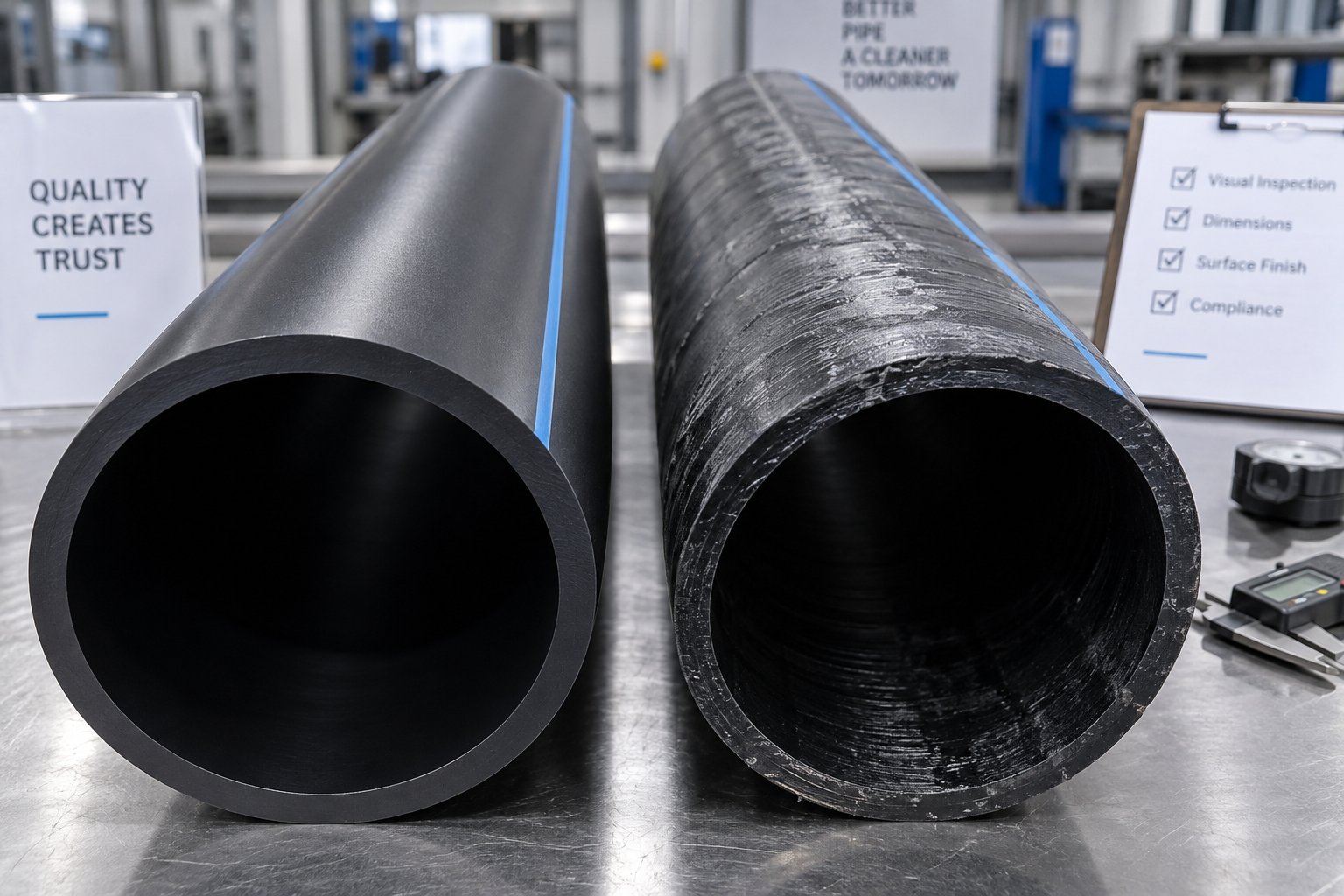
Surface quality is the first thing anyone notices on a finished pipe — and the first thing an inspector flags. Three surface defects dominate extruded pipe manufacturing: shark skin, melt fracture, and general surface roughness. Each has a distinct visual signature and a different root cause, even though all three relate to what happens at or near the die exit.
Shark skin appears as fine, regularly spaced ridges or a matte, textured surface running along the pipe's length. It develops when the polymer melt experiences excessive shear stress at the die lip. As the outer layer of melt accelerates through the narrow die gap, the surface layer stretches faster than the polymer's molecular chains can relax. The result is a stick-slip fracture pattern confined to the outermost skin. Reducing extrusion speed, raising die temperature slightly to lower melt viscosity, or widening the die gap all help the surface layer exit more smoothly. Some producers also apply a small amount of fluoropolymer processing aid to the resin blend, which creates a slip layer at the die wall and reduces surface shear stress.
Melt fracture is more severe. Instead of fine ridges, you'll see spiral distortions, wavy patterns, or gross surface irregularities that penetrate deeper into the wall. This defect occurs when the overall shear rate inside the die exceeds the polymer's critical threshold — the point where laminar melt flow breaks down into chaotic, turbulent movement. The fix is straightforward in concept but demands careful execution: lower the extrusion rate, increase melt temperature to reduce viscosity, or redesign the die land length to reduce shear. Extrusion troubleshooting resources confirm that slowing output speed and raising die temperature are the primary corrective steps for melt fracture.
Surface roughness without a clear pattern — a generally dull, grainy, or pitted finish — usually points to degraded melt quality upstream of the die. Contamination, partially melted resin particles, or thermal degradation products create inconsistencies in the melt stream that the die faithfully reproduces on the pipe surface. A worn screw and barrel are frequent culprits here. As Plastics Technology explains, increasing flight clearance from screw wear reduces pumping efficiency and heat transfer at the barrel wall, leading to inconsistent melt temperatures and poor homogenization. Contamination from degraded material trapped in dead spots of the die head can produce a similar effect. Regular screen changes, die cleaning, and screw/barrel inspection are the preventive measures.
Dimensional Defects Including Ovality and Wall Variation
Dimensional defects cost more than surface flaws because they often result in outright rejection — a pipe that fails to meet its specified outer diameter or wall thickness tolerance cannot be sold. Two dimensional defects appear most frequently: wall thickness variation and ovality.
Wall thickness variation shows up as measurably thicker and thinner zones around the pipe's circumference or along its length. Circumferential variation — one side consistently thicker than the other — almost always traces back to die misalignment or uneven melt distribution. If the die ring is off-center relative to the mandrel tip, the annular gap becomes wider on one side, and more material flows through the larger opening. Correcting this requires recentering the die using the adjustable bolts and verifying concentricity with a dial indicator.
Longitudinal variation — thickness that changes along the pipe's length — points to a different set of causes. Unstable melt pressure from the extruder, inconsistent haul-off speed, or surging feed rates all create periodic thick-thin patterns. Dimensional control guidance for pipe extrusion identifies puller stability and output consistency as primary suspects when wall thickness varies along the pipe length, while circumferential bias typically points to alignment and centering issues.
Ovality — a pipe that measures round at the die exit but arrives at the cutter slightly egg-shaped — is one of the most frustrating defects to chase. When ovality is consistent and repeatable from run to run, the cause is almost certainly mechanical: worn calibration sleeves, misalignment between the die and the calibration tank, or uneven support rollers inside the tank. When ovality comes and goes during production, the source is more likely a process fluctuation — unstable vacuum level, uneven cooling water coverage, or temperature swings in the calibration tank. Fixing intermittent ovality requires stabilizing these dynamic conditions before investigating mechanical wear.
Internal Defects Such as Voids and Bubbles
Internal defects are invisible on the surface but devastating to performance. Voids and bubbles trapped within the pipe wall create localized weak points that become failure initiation sites under sustained pressure. Two primary causes account for the vast majority of these defects.
Moisture in the resin is the most common source of bubbles. Even though HDPE has low moisture absorption compared to hygroscopic polymers, surface moisture on pellets — from humid storage conditions or condensation during transport — vaporizes inside the heated barrel and becomes trapped as gas pockets in the melt. These pockets remain as discrete bubbles in the pipe wall after cooling. The reference material from extrusion engineering sources notes that clear bubbles specifically indicate moisture content, while dark specks signal degraded material — a useful diagnostic distinction on the production floor.
Insufficient venting or air entrainment is the second major cause. If the extruder screw design lacks an adequate decompression zone or the feed throat isn't properly sealed, ambient air gets dragged into the barrel along with the pellets. This air has no way to escape once the melt compresses in the metering zone, so it becomes embedded as voids. Intermittent bubbles — ones that appear and disappear unpredictably — often point to leaks or instability in the feed system rather than a moisture issue.
Corrective action is systematic: verify resin drying conditions, check hopper and feed throat sealing, inspect venting ports for blockages, and confirm that the screw design provides adequate decompression for the HDPE grade being processed. When bubbles persist despite proper drying, the problem almost certainly lies in equipment rather than material.
The table below consolidates every defect discussed into a single diagnostic reference:
| Defect | Visual Symptom | Root Cause | Component Involved | Corrective Action |
|---|---|---|---|---|
| Shark skin | Fine, regularly spaced ridges or matte texture on the pipe surface | Excessive shear stress at the die lip exit | Extrusion die head (die land and lip zone) | Reduce extrusion speed, raise die temperature, widen die gap, or add fluoropolymer processing aid |
| Melt fracture | Spiral distortions, wavy patterns, or gross surface irregularities | Shear rate exceeds the polymer's critical flow threshold | Extrusion die head and extruder (output rate) | Lower extrusion rate, increase melt temperature, lengthen die land, or redesign flow channel geometry |
| Surface roughness | Dull, grainy, or pitted surface without a repeating pattern | Degraded melt quality from contamination, thermal degradation, or worn screw/barrel | Screw and barrel, screen changer, die head (dead spots) | Inspect and replace worn screw/barrel, clean die head, increase screen change frequency, verify barrel temperature profile |
| Wall thickness variation (circumferential) | One side of the pipe consistently thicker than the opposite side | Die ring off-center relative to the mandrel; uneven melt distribution | Die head (centering bolts and mandrel alignment) | Re-center die using adjusting bolts; verify concentricity with dial indicator; check melt distribution channels |
| Wall thickness variation (longitudinal) | Thickness changes periodically along the pipe length | Unstable melt pressure, surging feed rate, or inconsistent haul-off speed | Extruder (feed system, screw), haul-off unit, melt pump | Stabilize feed rate, verify haul-off servo consistency, add or inspect melt pump, check for screen pack blockage |
| Ovality (consistent) | Pipe cross-section is egg-shaped, repeatable across runs | Mechanical misalignment or worn calibration sleeve | Vacuum calibration tank (sleeve, alignment), die-to-tank centering | Replace worn sleeve, re-align calibration tank to die centerline, inspect internal support rollers |
| Ovality (intermittent) | Roundness varies unpredictably during a production run | Unstable vacuum level, uneven cooling water coverage, or temperature fluctuation | Vacuum calibration tank (vacuum pump, spray nozzles, water system) | Stabilize vacuum regulation, clean spray nozzles, verify water flow uniformity and temperature consistency |
| Voids and bubbles (persistent) | Small gas pockets visible in cross-section or detected by ultrasonic testing | Moisture in resin vaporizing inside the barrel | Dryer, material storage and handling | Verify drying temperature and duration, check desiccant condition, improve resin storage to prevent condensation |
| Voids and bubbles (intermittent) | Bubbles appear and disappear unpredictably | Air entrainment through feed throat or insufficient screw venting | Feed throat seal, screw design (decompression zone), hopper | Seal feed throat, inspect vent ports for blockage, confirm screw design provides adequate decompression |
One thread runs through nearly every row in that table: melt quality. Shark skin, melt fracture, surface roughness, and bubbles all connect — directly or indirectly — to what happens inside the extruder barrel. A worn screw with excessive flight clearance delivers inconsistent melt temperature and poor homogenization. A barrel with degraded heating zones creates hot spots that cause localized degradation. These upstream issues cascade into defects that surface far downstream, making them harder to diagnose if you're only looking at the die or the cooling tank.
That connection between equipment condition and product quality extends beyond troubleshooting individual defects. It ties directly into the standards and certification requirements your pipes must satisfy — because every tolerance in those standards ultimately traces back to the precision and repeatability of your production equipment.
Standards and Certifications Every HDPE Plant Must Know
Dimensional tolerances, pressure ratings, and material classifications aren't just numbers on a datasheet — they're contractual obligations. Every pipe leaving an hdpe extrusion line destined for a water main, gas network, or industrial application must satisfy a specific set of standards. Fail to meet them, and the entire production run faces rejection, regardless of how smooth the surface looks or how consistent the wall feels to the touch. The real question for any pipe producer is this: does your equipment have the precision to consistently hold the tolerances those standards demand?
Key International Standards for HDPE Pipe
Dozens of standards govern HDPE pipe worldwide, but they cluster around three primary application categories. Knowing which standard applies — and what it actually requires — is the first step toward aligning your pe extrusion line capabilities with market requirements.
Water supply standards:
- ISO 4427 — the global benchmark for polyethylene pipes used in potable water systems. It specifies dimensional requirements, pressure ratings based on the material's minimum required strength (MRS), and long-term hydrostatic performance criteria. ISO 4427 focuses heavily on long-term strength and hydrostatic pressure resistance, making it the foundational reference for most international water projects.
- EN 12201 — the European adaptation of ISO 4427, adding region-specific requirements for jointing methods, installation procedures, and testing protocols. It provides comprehensive coverage from design through testing, ensuring robust pipe system integrity across European public and private water supply networks.
- ASTM F714 — widely used in the United States for large-diameter HDPE water pipe, specifying dimensions, tolerances, pipe stiffness, and pressure ratings for municipal and industrial water transportation systems.
- ASTM D3035 — covers smaller-diameter PE pipes (typically under 3 inches) used in pressurized water distribution, with dimension ratios and tolerances tailored to residential and commercial networks.
- AWWA C906 and C901 — specialized waterworks standards covering large-diameter and small-diameter HDPE pressure pipes respectively, with emphasis on durability, joint performance, and resilience under environmental stress.
Gas distribution standards:
- ISO 4437 — the international standard for polyethylene pipes carrying natural gas. Similar in structure to ISO 4427, it adds safety requirements for gas permeability and fire resistance — critical for both above-ground and below-ground gas distribution networks.
- EN 1555 — the European counterpart to ISO 4437, featuring stringent testing on joint integrity and maintaining gas quality, mandatory for gas distribution in EU-regulated markets.
- ASTM D2513 — the primary North American standard for thermoplastic gas pressure pipe, tubing, and fittings.
Industrial and drainage standards:
- ISO 8772 — covers HDPE pipes for non-pressure underground drainage and sewerage applications.
- ASTM F894 — addresses HDPE profile-wall pipe for storm sewer and subsurface drainage.
- ASTM D3350 — not a pipe standard per se, but a critical material classification standard that categorizes HDPE resin based on density, cell classification, and melt index. It serves as the foundation for specifying base resin quality across all pipe applications.
One detail that often catches newer producers off guard: material designation matters as much as dimensional compliance. PE80 and PE100 aren't just marketing labels. They refer to the resin's minimum required strength — 8.0 MPa and 10.0 MPa respectively at 20 degrees C over a 50-year design life. A PE100 compound allows thinner walls at the same pressure rating compared to PE80, which directly affects extrusion parameters. Thinner walls mean faster cooling, higher line speeds, and different haul-off tension settings. Switching resin grades on the same hdpe extrusion line without adjusting the full process recipe — temperatures, screw speed, vacuum level, cooling profile — is a reliable way to produce out-of-spec pipe.
How Equipment Precision Ensures Standard Compliance
Every standard listed above specifies dimensional tolerances. ISO 4427 and EN 12201, for example, define maximum allowable deviations for outer diameter, wall thickness, and ovality. For a 315 mm SDR 11 PE100 pipe, the wall thickness must fall within a narrow tolerance band — and ovality (the difference between maximum and minimum OD measured at the same cross-section) cannot exceed a defined percentage of the nominal diameter.
Those tolerance numbers translate directly into equipment performance requirements at three critical stations on the line:
- Vacuum calibration tank — responsible for locking in the pipe's outer diameter and roundness. If the calibration sleeve is worn, misaligned, or the vacuum level fluctuates, the OD and ovality tolerances specified by the standard become impossible to hold. Sleeve machining precision — often within ±0.02 mm — must match or exceed the standard's dimensional requirements.
- Haul-off unit — controls wall thickness through its speed ratio with the extruder. Even minor speed fluctuations create longitudinal thickness variations that push measurements outside the standard's tolerance band. Servo-driven haul-offs with closed-loop speed control are effectively mandatory for any hdpe plant producing to ISO or ASTM specifications.
- Cutting unit — determines length accuracy and end-squareness. Standards specify minimum pipe lengths and squareness tolerances for the cut ends. A worn saw blade or poorly synchronized traveling cutter introduces angled cuts that complicate jointing and can lead to field rejection.
Think of it this way: the standard defines what the pipe must be. The equipment determines what the pipe can be. When equipment precision falls below the standard's tolerance requirements, no amount of operator skill bridges the gap.
In-Line Quality Monitoring Systems
Relying on post-production inspection alone is a losing strategy. By the time an operator measures a cut pipe with calipers and finds it out of tolerance, hundreds of meters of non-conforming product may already be stacked on the warehouse floor. Modern pe extrusion line configurations solve this with continuous in-line measurement systems that detect deviations in real time — often before they become visible to the human eye.
Three monitoring technologies form the backbone of in-line quality assurance:
- Ultrasonic wall thickness measurement — sensors mounted around the pipe circumference use pulse-echo ultrasonic signals to measure wall thickness at multiple points simultaneously. These systems detect thickness variations as small as ±0.01 mm and provide continuous feedback that can be linked to automatic extrusion speed or haul-off speed adjustment. For producers working to ISO 4427 or EN 12201 wall thickness tolerances, ultrasonic monitoring is the most reliable method of ensuring every meter of pipe complies.
- Laser diameter measurement — non-contact laser scanners measure the pipe's outer diameter and ovality continuously as it passes through the cooling section. Multi-axis laser gauges capture diameter readings at several orientations per scan cycle, calculating both mean OD and ovality in real time. When readings drift toward the tolerance boundary, the system alerts operators or automatically adjusts vacuum level in the calibration tank to bring the diameter back within specification.
- Gravimetric (weight-per-meter) control — this system continuously weighs the pipe as it passes a checkpoint on the line, calculating mass per unit length. Because mass per meter correlates directly with wall thickness at a given diameter, gravimetric control provides an independent cross-check against ultrasonic measurements. It's particularly valuable for detecting slow drift in wall thickness that might escape point-measurement systems.
Together, these three systems create an overlapping measurement net that catches dimensional deviations before non-conforming pipe reaches the stacker. The data they generate also serves a documentation purpose: many standards and end-user specifications now require statistical process control (SPC) records demonstrating that dimensional parameters stayed within tolerance throughout the production run — not just at the start and end.
Compliance, then, isn't a one-time certification event. It's a continuous capability that depends equally on equipment precision and real-time monitoring. Maintaining that capability over months and years of production introduces its own set of challenges — particularly around the wear-prone components that most directly affect dimensional consistency.
Selecting and Maintaining Your HDPE Pipe Production Line
Equipment precision degrades with every operating hour. The standards, tolerances, and monitoring systems covered earlier only deliver value if the mechanical components behind them remain in peak condition. That reality shifts the conversation from "what should the line do?" to two equally important questions: how do you choose the right line in the first place, and how do you keep it performing at its best over years of continuous production? Whether you're evaluating your first hdpe pipe production line or optimizing one that's been running for a decade, the answers below bridge the gap between knowledge and action.
Key Criteria for Evaluating an Extrusion Line
Imagine walking into a supplier's showroom with a vague idea of what you need. You'll leave with a line that's either undersized for your growth plans or overbuilt for your actual market. A structured evaluation framework prevents both mistakes. Here are the six criteria that should anchor every purchasing decision:
- Output requirements — start with the throughput your market demands, measured in kg/h or meters/min for your target pipe sizes. A line rated at 400 kg/h may suit medium-diameter municipal pipe, but large-diameter infrastructure projects consuming 1,200 kg/h or more require fundamentally different extruder and drive configurations.
- Pipe diameter range — determine the full range of diameters you plan to produce, not just today's orders. A line covering 110–630 mm offers versatility across mid-range applications, while a dedicated large-diameter system for 630–1600 mm serves a narrower but higher-value market. Switching between widely different size ranges on a single line is rarely practical.
- Layer configuration — single-layer lines are simpler and less expensive, but multi-layer co-extrusion opens the door to striped pipes, recycled-core structures, and peelable protective skins. Each additional layer adds a co-extruder and increases die head complexity, so match the configuration to your actual product portfolio.
- Automation level — recipe-based PLC control, gravimetric dosing, inline ultrasonic measurement, and automated diameter correction reduce operator dependency and improve consistency. Higher automation costs more upfront but pays dividends in reduced scrap, lower labor requirements, and faster changeovers.
- Energy efficiency — specific energy consumption varies significantly across lines. Advanced systems achieve 0.28–0.32 kWh/kg compared to 0.40 kWh/kg for standard configurations — a difference that compounds into substantial utility savings over thousands of operating hours annually.
- After-sales support — spare parts availability, remote diagnostic capability, and on-site service response times matter more than most buyers realize during procurement. A supplier guaranteeing 48-hour dispatch for critical wear parts prevents the kind of extended downtime that erases months of operating margin.
Weighing these criteria against your specific production targets and product mix prevents the two most expensive mistakes in the hdpe pipe manufacturing process: buying too little capacity and choking growth, or buying too much and carrying idle capital.
Maintenance Priorities for Long-Term Performance
Even the best-specified line deteriorates without disciplined maintenance. The challenge is knowing where to focus. Not every component wears at the same rate or carries the same consequence when it degrades. A practical maintenance checklist organized by frequency keeps the line inside its operating window and catches drift before it becomes downtime:
- Screw and barrel inspection — measure bore diameter and screw flight clearance monthly at the feed, compression, and metering zones. Track these measurements over time. Increasing clearance reduces pumping efficiency, raises energy consumption, and degrades melt homogeneity — all of which silently erode pipe quality long before a visible defect appears.
- Die head cleaning — inspect the die lip and flow channels weekly for resin buildup, carbon deposits, and discoloration. Degraded material trapped in dead spots introduces streaks, black specks, and wall thickness irregularities. Full disassembly and cleaning should follow every extended production run or material change.
- Calibration sleeve replacement — check sleeve bore dimensions and interior surface condition during every product changeover. A worn or scored sleeve cannot hold the tight OD and ovality tolerances that ISO 4427 and EN 12201 require. Chrome-plated stainless steel sleeves last longer than brass but still require periodic measurement against baseline dimensions.
- Haul-off roller and belt maintenance — inspect belt surfaces for wear, glazing, or embedded debris weekly. Verify encoder feedback accuracy monthly by comparing displayed speed against a known reference. Even small speed errors translate directly into wall thickness deviation — the one dimensional parameter most standards measure most strictly.
- Cooling system upkeep — clean water filters, strainers, and spray nozzles weekly. Clogged nozzles reduce cooling uniformity, creating the kind of uneven crystallization that shows up as ovality or residual stress — defects that trace back to cooling but are often misdiagnosed as die or calibration problems.
- Electrical and control system checks — clean VFD heat sinks, verify cabinet ventilation fans, and back up PLC/HMI parameters monthly. A failed controller without a current parameter backup can turn a simple hardware swap into days of reprogramming and re-tuning.
The pattern across this checklist is clear: most maintenance items are quick, low-cost inspections. The expensive failures they prevent — unplanned shutdowns, mass scrap runs, missed delivery deadlines — cost orders of magnitude more than the time spent checking.
When to Replace Your Screw and Barrel
Among all wear-prone components, the screw and barrel deserve the most attention because their condition governs everything downstream. You'll notice the signs of wear gradually — and that gradual onset is exactly what makes it dangerous. Operators unconsciously compensate by raising barrel temperatures, increasing screw speed, or adjusting haul-off tension, masking the underlying degradation until the compensation runs out of range.
Three symptoms signal that replacement is overdue rather than optional:
- Decreased output at the same screw speed — widening clearance between screw flights and the barrel bore allows melt to leak backward past the flights instead of being pushed forward. The extruder works harder to deliver less material.
- Inconsistent melt quality — uneven temperatures, visible gels, or periodic surging in melt pressure point to poor heat transfer and inconsistent shear across a worn barrel surface. These melt inconsistencies flow directly into the wall thickness variation and surface roughness defects covered earlier.
- Higher energy consumption per kilogram — a worn screw-barrel pair converts motor energy into heat and backflow rather than productive pumping. If your specific energy consumption (kWh/kg) trends upward at stable operating conditions, the screw and barrel are the most likely cause.
Replacing a screw and barrel is not a full line replacement — it's a targeted intervention that restores melt quality, throughput, and energy efficiency to near-original levels. The key is sourcing components engineered to match your specific application demands. For facilities producing hdpe extrusions or running any pipe, film, sheet, pelletizing, recycling, or general-purpose extrusion process, NANHAIYA's single screw barrel program provides custom and replacement barrels designed around the metallurgy, bore tolerances, and thermal zone layouts that each application requires. Rather than adapting a generic barrel to your process, application-specific engineering ensures the replacement performs as well as — or better than — the original, extending the productive life of your entire line without the capital expenditure of new equipment.
Every chapter of this guide has reinforced a single principle: an HDPE pipe extrusion line is a system of interdependent components, and the quality of the finished pipe reflects the weakest link in that chain. Understanding how resin transforms into pipe — from pellet drying through plasticization, die shaping, vacuum calibration, cooling, and cutting — gives producers the diagnostic language to identify problems at their source rather than chasing symptoms downstream. Pairing that process knowledge with disciplined equipment selection, proactive maintenance, and timely component replacement is what separates facilities that consistently produce flawless, standards-compliant pipe from those that spend their days troubleshooting.
Frequently Asked Questions About HDPE Pipe Extrusion Lines
1. What are the main components of an HDPE pipe extrusion line?
An HDPE pipe extrusion line consists of a material handling system (hopper, gravimetric feeder, dryer), a single-screw extruder with motor, gearbox, barrel, and screw, a screen changer, an optional melt pump, an annular extrusion die head, a vacuum calibration tank for sizing, spray cooling tanks, a caterpillar haul-off unit, a planetary or chip-free cutting saw, and a stacker or coiler. Each component performs a specific function and passes the product to the next stage in a continuous workflow. Maintaining these components — especially the screw and barrel — is critical to consistent pipe quality. Suppliers like NANHAIYA offer custom and replacement single screw barrels engineered for pipe extrusion applications at nhyscrews.com.
2. What screw L/D ratio is recommended for HDPE pipe extrusion?
Industry best practice for HDPE pipe extrusion calls for an L/D (length-to-diameter) ratio between 30:1 and 33:1. This range provides sufficient barrel length for thorough melting and homogenization of semi-crystalline HDPE without the thermal degradation risks associated with excessively long residence times. Ratios below 28:1 risk pushing incompletely melted resin into the die head, while ratios above 36:1 can degrade HDPE's molecular structure and reduce long-term stress crack resistance. Screw diameters commonly range from 45 mm for small-diameter tubing to 120 mm or larger for heavy-wall, large-bore pipe production.
3. How does vacuum calibration work in HDPE pipe production?
Vacuum calibration creates a controlled pressure differential to size the pipe immediately after it exits the die head. The still-soft pipe enters a sealed, water-filled tank where air pressure has been reduced below atmospheric level. Since atmospheric pressure is maintained inside the pipe through the die mandrel, the pressure difference pushes the soft outer wall outward against a precision-machined calibration sleeve — typically brass or chrome-plated stainless steel — machined to the exact target outer diameter. Water cooling rapidly solidifies the surface, locking in the pipe's diameter and roundness. Key control parameters include vacuum level (0.02–0.06 MPa negative pressure), water temperature (15–20 degrees C), sleeve material, and sleeve length.
4. What causes common defects in HDPE pipe extrusion and how can they be fixed?
Common HDPE pipe extrusion defects include shark skin (fine ridges caused by excessive die lip shear stress — fix by reducing speed or raising die temperature), melt fracture (spiral distortions from exceeding the polymer's critical shear rate — fix by lowering output or increasing melt temperature), wall thickness variation (from die misalignment or unstable melt pressure — fix by recentering the die or stabilizing feed rate), ovality (from worn calibration sleeves or uneven cooling — fix by replacing sleeves and stabilizing vacuum), and voids or bubbles (from resin moisture or air entrainment — fix by verifying drying conditions and sealing the feed throat). Many defects trace back to worn screw and barrel components that degrade melt quality over time.
5. What international standards apply to HDPE pipes and how do they affect extrusion line requirements?
Major standards include ISO 4427 and EN 12201 for water supply, ISO 4437 and EN 1555 for gas distribution, ASTM F714 and D3035 for North American water pipe, and ASTM D2513 for gas pipe. These standards specify tight dimensional tolerances for outer diameter, wall thickness, and ovality that directly translate into equipment precision requirements. The vacuum calibration tank must hold OD tolerances within fractions of a millimeter, the haul-off unit must maintain servo-controlled speed consistency for wall thickness uniformity, and in-line monitoring systems — ultrasonic wall thickness sensors, laser diameter gauges, and gravimetric controls — are essential for continuous compliance verification throughout each production run.
Written by
Nanhaiya Technical Team
Zhoushan Nanhaiya Plastic Machinery Co., Ltd.
The Nanhaiya technical team supports screw and barrel manufacturing projects through application review, technical communication, custom manufacturing coordination, and production and quality control.
Discuss Your Application
Related Articles
More insights on screw barrel technology and plastics processing.

Extruder Machine Decoded: From Raw Pellet To Finished Product
Oct 6, 2026
Learn how an extruder machine works, compare single-screw vs. twin-screw types, and get expert guidance on specs, troubleshooting, and selection.
Read Article
PE Pipe Making Machine Decoded: From Raw Resin to Flawless Pipe
Oct 4, 2026
Learn how a PE pipe making machine works, from resin to finished pipe. Covers components, material grades, automation, troubleshooting, and buyer selection tips.
Read Article
PVC Profile Making Machine Decoded: From Raw Resin To Profit
Oct 3, 2026
Learn how a PVC profile making machine works — extrusion process steps, key technical parameters, die design, calibration methods, maintenance, and total cost of ownership.
Read ArticleLooking for something else?
Search by material, symptom or product and jump straight to the relevant page.
These are navigation suggestions based on keyword matching — not a quotation, not a delivery commitment, and not a substitute for engineering review. Final specification is confirmed by our engineers against your drawings and processed material.
Need help with screw barrel selection?
Share your machine model, processed material and application. Our team can help with pricing and technical support.