

What Are Extruder Screws and Why They Matter
Every plastics processing line — whether it produces film, pipe, profiles, or molded parts — depends on one component more than any other. That component is the extruder screw, and getting its geometry wrong is one of the fastest ways to cripple output quality and throughput.
What Is an Extruder Screw
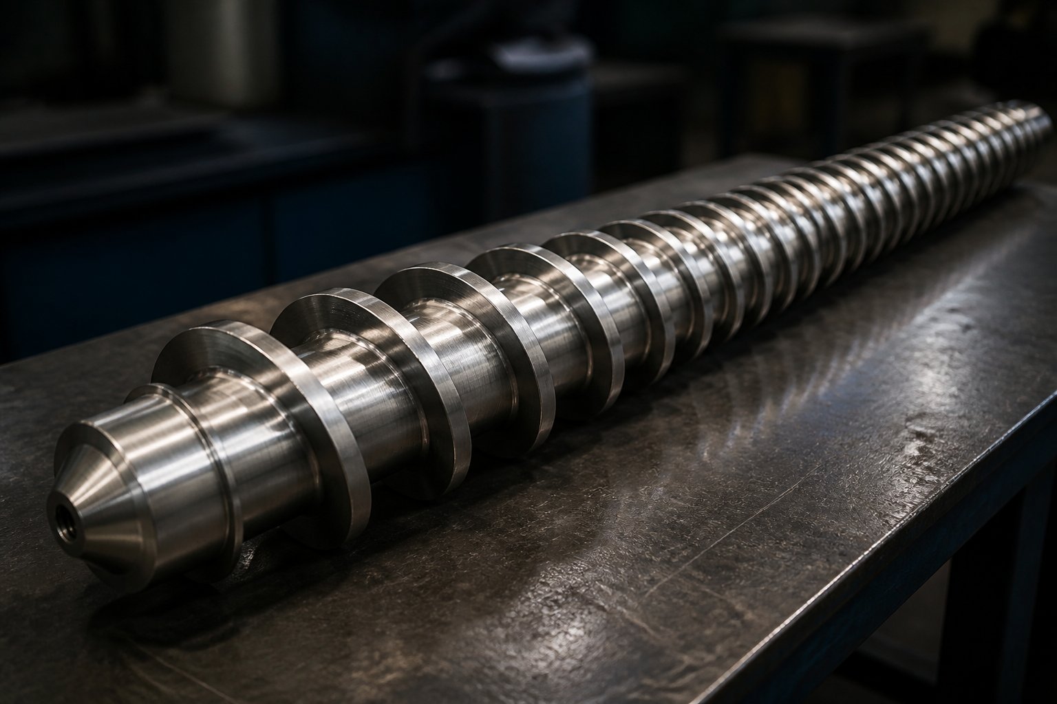
An extruder screw is a precision-engineered helical shaft housed inside a heated barrel that conveys, compresses, melts, and homogenizes polymer material as it rotates. Solid pellets or powder enter at one end, and a uniform, pressurized melt exits the other — ready to be shaped by a die or injected into a mold. The screw's geometry directly governs melt quality, throughput rate, and energy efficiency, making it the functional core of any screw extruder or injection molding machine.
Why Screw Design Matters for Processing Performance
Imagine running a high-output extrusion line only to find unmelted particles embedded in your finished product, or watching energy costs climb because the screw generates excessive shear heating. These are not hypothetical scenarios — they are the direct consequences of mismatched screw geometry. Selecting the wrong design leads to poor melt homogeneity, degraded polymers, surging output, and wasted energy. The pressure within the compression zone alone can reach 400 bar, as noted by SpecialChem's extrusion guide, underscoring just how critical the screw's dimensional accuracy is to stable processing.
The extruder screw accounts for roughly 80 percent of the work performed in a plastics extrusion system, making its design the single most impactful variable in processing quality.
This article serves as a technical reference for process engineers, machine operators, maintenance teams, and procurement professionals who need to move beyond guesswork. You'll find a zone-by-zone breakdown of screw anatomy, clear definitions of geometry parameters like L/D ratio and compression ratio, a comparison of screw types from barrier to vented configurations, guidance on matching screw design to specific polymer families, and a practical framework for wear identification and replacement planning. The goal is straightforward: give you the knowledge to specify, evaluate, and maintain extruder screws with confidence.
That confidence starts with understanding what happens inside each zone of the screw — where solid pellets transform into a pressurized, homogeneous melt through a carefully orchestrated sequence of conveying, compression, and metering.
Anatomy of an Extruder Screw Zone by Zone
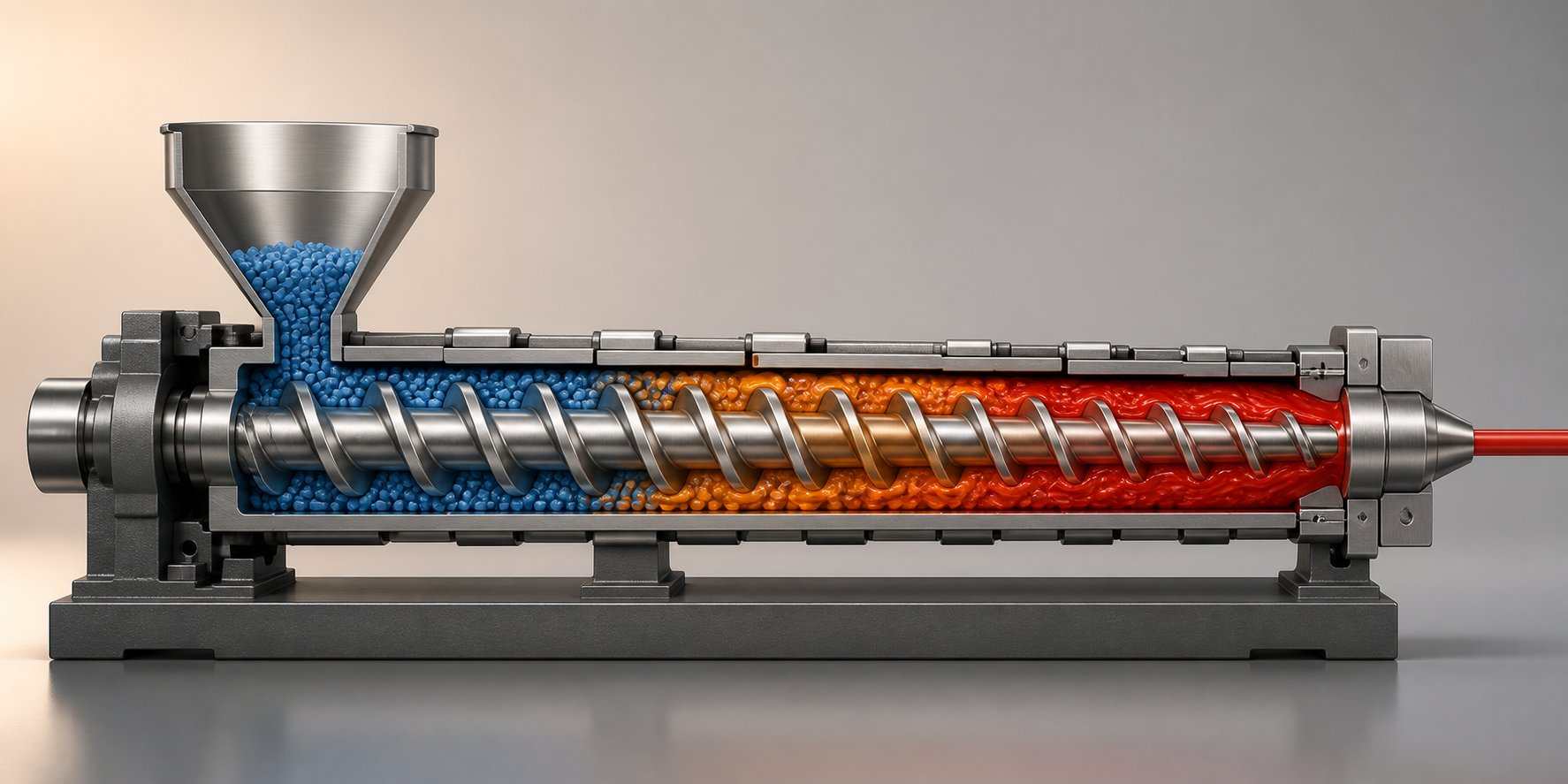
Solid plastic pellets don't simply melt the moment they touch hot metal. Inside the extruder barrel, they pass through a carefully staged sequence of physical transformations — each one governed by a distinct section of the screw. A standard single-screw design divides its flighted length into three functional zones: feed, transition (compression), and metering. Each zone has a unique channel depth profile and a very specific job. When any one of these zones is incorrectly proportioned, the entire downstream process suffers.
Feed Zone Structure and Solid Conveying
The feed zone sits directly beneath the hopper and extends along the first portion of the screw — typically occupying 50 to 60 percent of the total flighted length. You'll notice that this section features the deepest channel depth of any zone. That generous depth serves a practical purpose: it accommodates the bulk density of incoming solid pellets or powder, which occupy far more volume than the same mass of molten polymer.
Conveying in this zone relies almost entirely on frictional drag. As the screw rotates, solid material is dragged forward by the friction between the pellets and the extruder barrel wall — not by the screw itself. In fact, if the pellets were to stick to the screw root instead of the barrel, forward movement would stall entirely. This is why the extruder feed barrel interface is so critical. Many modern machines use a grooved feed throat — a section of the barrel bore machined with longitudinal grooves and water-cooled to keep pellets from prematurely softening. These grooves dramatically increase the friction coefficient against the barrel wall, boosting solid conveying efficiency and allowing higher throughput at a given screw speed.
Consistent feeding is also about compaction. As the flights push pellets forward, trapped air between granules is squeezed backward toward the hopper. If this zone is too short or the channel too shallow, air entrapment leads to erratic feeding, reduced output, and potential surging downstream.
Transition and Compression Zone Mechanics
Here's where the real transformation happens. In the transition zone — sometimes called the compression zone — the channel depth gradually decreases from the deep feed section toward the shallow metering section. This tapering geometry compresses the solid bed against the heated barrel wall and generates the mechanical energy needed for melting.
Picture the process at a microscopic level. A thin film of molten polymer forms first at the barrel surface, where conductive heat transfer is highest. As the screw rotates, the leading edge of the advancing flight scrapes this melt film off the barrel wall and sweeps it into a growing melt pool on the pushing side of the screw channel. Meanwhile, the solid bed occupies the trailing side, pressed firmly against the barrel by the decreasing channel depth.
As melting progresses along the length of the transition zone, the solid bed width narrows and the melt pool expands. This is a delicate balance — if the compression happens too aggressively, excessive shear can overheat sensitive polymers. If it happens too gradually, unmelted solids survive into the metering zone and end up as defects in the final product. The compression ratio, which compares the feed channel depth to the metering channel depth, quantifies exactly how aggressive this transition is. Getting it right for each polymer family is one of the most consequential design decisions in extruder screw engineering.
Interestingly, shear heating generated in this zone and the metering zone accounts for 60 to 80 percent of the total heat input in many extrusion setups — barrel heaters contribute the remainder. That statistic underscores just how much the screw's geometry, rather than external heating, drives the melting process.
Metering Zone and Melt Delivery
By the time polymer reaches the metering zone, it should be fully molten. This final section features the shallowest and most uniform channel depth, and it functions essentially as a melt pump. Its job is to deliver a homogeneous melt at consistent pressure and temperature to the die or injection nozzle.
Two opposing flow mechanisms compete inside this zone. Drag flow pushes material forward — driven by the relative motion between the rotating screw and the stationary barrel. Pressure flow acts in the opposite direction, forcing melt backward through the channel because of the resistance created by the die, screen pack, or breaker plate downstream. The net output of the extruder is the difference between these two flows. A well-designed metering zone maximizes drag flow while minimizing backflow leakage over the flight lands, where the tight clearance between the screw flight and the barrel bore becomes critical.
If the metering zone is too short, pressure fluctuations cause surging — that frustrating cycle of output variation that ruins dimensional consistency. If it's too long relative to the feed and transition zones, the barrel extruder system wastes energy by over-working already-molten polymer without meaningful benefit.
| Zone Name | Channel Depth Characteristic | Primary Function | Key Design Consideration |
|---|---|---|---|
| Feed Zone | Deepest and constant | Accept solid pellets/powder and convey them forward via frictional drag against the barrel wall | Channel must be deep enough to accommodate bulk density of solids; grooved feed throat and cooling enhance conveying efficiency |
| Transition (Compression) Zone | Gradually decreasing from feed depth to metering depth | Compress the solid bed, generate shear heat, and progressively melt polymer through melt film formation | Compression ratio must match polymer's melting behavior — too aggressive causes degradation, too gentle leaves unmelted solids |
| Metering Zone | Shallowest and constant | Homogenize the melt and deliver it at stable pressure and temperature to the die | Channel depth and length must balance drag flow against pressure-driven backflow to ensure consistent output without surging |
Each zone's proportions — its length, channel depth, and the rate of depth change — are tailored to specific polymers and throughput targets. Mismatching any of these dimensions is one of the most common geometry mistakes that processors make, and it directly erodes output quality and efficiency. The parameters that define these dimensions have precise engineering names, and understanding their definitions is the next step toward specifying the right screw for any application.
Essential Screw Geometry Parameters Defined
Spec sheets for extruder screws are packed with abbreviations and ratios that get tossed around casually — L/D, compression ratio, helix angle — yet surprisingly few resources explain what these numbers actually mean or why they matter on the production floor. If you've ever ordered a replacement extrusion screw and struggled to translate a supplier's technical drawing into processing performance expectations, this section is your reference point.
L/D Ratio and Compression Ratio Explained
The L/D ratio is the screw's flighted length divided by its nominal diameter. Think of it as a measure of how much processing real estate the polymer gets as it travels from the feed throat to the discharge end. A shorter ratio like 20:1 provides less residence time and fewer opportunities for mixing — which is perfectly adequate for simple commodity resins with narrow melting ranges. Longer ratios of 30:1 or 36:1 give engineering resins the extended heat exposure and mixing length they need for thorough melting and homogenization. As detailed in twin screw design references, typical L/D values for co-rotating compounders range from 32:1 to 48:1, reflecting the need for multiple functional zones along the screw length.
Compression ratio compares the feed zone channel depth to the metering zone channel depth. It quantifies how aggressively the screw squeezes material during the melting transition. Different polymers demand very different values:
- Low compression (~1.5:1 to 2:1): Required for shear-sensitive materials like PVC, where over-compression causes thermal degradation and releases corrosive hydrochloric acid.
- Moderate compression (~2.5:1 to 3:1): Standard for polyolefins such as HDPE and PP, which undergo a significant density change during melting and need firm compaction to eliminate air pockets.
- High compression (~3.5:1 to 4.5:1): Suited to highly crystalline polymers like nylon or PET, which require aggressive energy input to break down their ordered molecular structures.
Selecting the wrong compression ratio is one of the most common — and most costly — geometry mistakes. Too high, and you degrade the polymer. Too low, and unmelted solids contaminate the finished product.
Flight Geometry and Channel Dimensions
Beyond the two headline ratios, several additional parameters define how material behaves inside the screw barrel assembly. Each one influences processing in a specific, measurable way:
- Helix angle: The angle between the screw flight and a plane perpendicular to the screw axis. For a standard square-pitch extruder screw barrel configuration (where pitch equals diameter), this value is approximately 17.66 degrees. Shallower angles favor pressure generation; steeper angles boost conveying capacity at the expense of pressure buildup.
- Pitch: The axial distance between consecutive flights on the same thread. Pitch directly controls how far material advances per screw revolution — a longer pitch increases conveying rate but reduces the number of flights per unit length, shifting the balance away from pressure development.
- Channel depth: The radial distance from the flight tip down to the screw root, calculated as H = (Do - Di) / 2. Deeper channels increase throughput capacity but reduce shear rate, since the velocity gradient across the channel decreases. This is a critical trade-off that ripples through melt temperature, mixing quality, and energy consumption.
- Flight width: The axial thickness of the flight at its tip, typically ranging from 8 to 12 percent of the screw diameter. Wider flights reduce available channel width and increase shear as material passes over the land, but they also limit leakage flow — the backward trickle of melt over the flight tip that steals from net output.
- Flight clearance: The radial gap between the flight land and the barrel wall. This is arguably the single most important wear indicator on any screw. A tight clearance minimizes leakage flow and maintains pumping efficiency. As this gap widens through abrasive or adhesive wear, output drops, melt temperature rises, and homogeneity suffers — often before any visual damage is apparent on the screw surface.
Understanding these parameters isn't academic trivia. When you specify a replacement screw or evaluate a new design, every one of these dimensions determines whether that screw will match your polymer, your throughput targets, and your quality requirements. Engineers who can articulate precise geometry specifications — rather than simply requesting a "general purpose" extrusion screw — consistently get better results from their suppliers and their production lines.
Geometry parameters define a screw's potential. But identical dimensions arranged into different design architectures produce dramatically different processing behaviors — which is exactly why the industry has developed distinct screw types, from simple single-flighted designs to barrier screws and specialized mixing configurations.
Types of Extruder Screws and When to Use Each
A screw with the right geometry parameters can still underperform if its fundamental design architecture doesn't match the processing demand. You might have the ideal compression ratio for your polymer, but if the application requires melting capacity or mixing intensity that the screw's layout simply cannot deliver, no amount of process adjustment will close the gap. As one practical observation from the manufacturing floor puts it: the screw type — not the process settings — sets the ceiling on what a line can do.
So which architecture fits which job? The answer depends on whether your bottleneck is melting, mixing, devolatilization, or simply cost-effective versatility.
General Purpose and Barrier Screw Designs
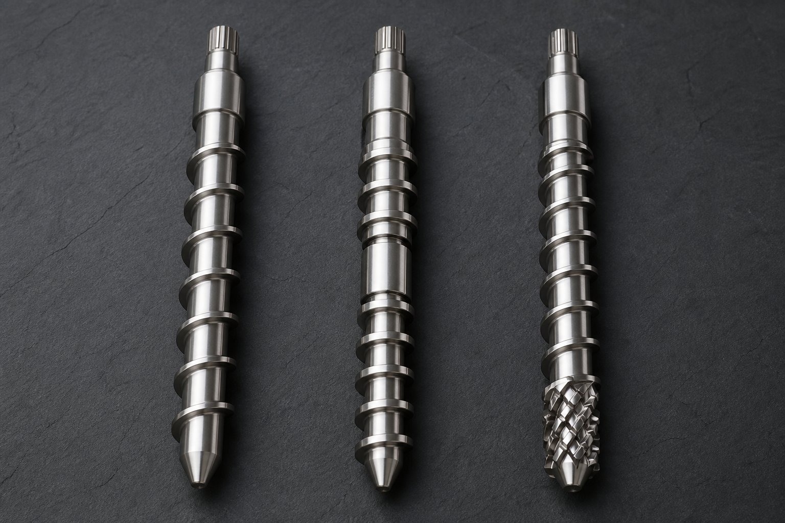
The standard single-flighted metering screw — the classic three-zone design — is the baseline against which every other type is measured. It handles conveying, compression, and metering with one continuous helical flight. For straightforward single-material extrusion of pipe, profiles, and sheet using commodity resins, this design delivers reliable performance at the lowest manufacturing cost. Its simplicity also means it's the easiest to maintain, replace, and adapt across different polymers. When melting capacity and mixing quality aren't limiting factors, there's no engineering reason to pay for a more complex screw.
That simplicity becomes a liability, though, when you push output rates higher or switch to harder-to-melt resins. A single-flighted design has finite melting capacity because molten and unmelted polymer share the same channel — the melt pool actually insulates the remaining solid bed from the barrel wall, slowing heat transfer right when you need it most.
Barrier screw designs solve this problem by introducing a secondary flight in the transition zone. This barrier flight physically separates the solid bed from the melt pool into two distinct channels. As polymer melts, it flows over the slightly lower barrier flight into the melt channel, while unmelted pellets remain confined in the solids channel until they too cross the barrier in molten form. The result is that no unmelted material can reach the metering zone — everything must melt to pass through.
Two principal barrier configurations dominate the industry. The crossing type, commonly called the Maillefer barrier, was one of the earliest designs. It features a barrier flight that crosses over the main flight path, creating a geometry where the solids channel narrows gradually without an abrupt restriction at the start. This gentler introduction is particularly advantageous for hard or slippery polymers whose fragile solid beds don't easily reshape to accommodate sudden cross-section changes. The Barr type, a parallel barrier design introduced later, runs the barrier flight roughly parallel to the main flight. As screw designer Jim Frankland explains, parallel barriers typically offer about one-third more surface area in the solids channel compared with crossing types of the same axial length — translating to greater melting capacity for polymers with higher energy requirements, such as those with elevated melting points or strong shear-thinning behavior.
A modified variant sometimes called the Dray-Lawrence type increases the helix angle beyond standard pitch in the barrier section. This gets more volume into the barrier zone for higher throughput, though the melting-capacity improvement per unit length is modest — under 10 percent — because fewer barrier flight turns fit the same axial distance.
When do barrier designs justify their higher cost? Whenever a conventional screw has hit its melting limit — showing up as unmelted particles in the product, output surging at the die, or melt temperature inconsistency. For high-output film lines, pipe extrusion with polyolefins, and engineering resin processing, the output stability and product quality gains typically pay back the investment quickly. Barrier screws also appear in demanding injection screw applications where shot-to-shot consistency depends on complete, repeatable melting.
Mixing and Vented Screw Configurations
Melting is only half the equation for many screw extruders. When you introduce colorants, fillers, or additives, the screw also needs to distribute or disperse those components uniformly through the melt. Standard three-zone and even barrier designs have minimal mixing capability — they rely on the natural flow patterns in the screw channel, which are insufficient for serious blending tasks. That's where dedicated mixing elements come in, and understanding the distinction between distributive and dispersive mixing is essential to choosing correctly.
Distributive mixing elements repeatedly divide, reorient, and recombine the melt stream without applying intense shear. Their goal is spatial uniformity — spreading an additive evenly throughout the melt. Common designs include:
- Pin mixers: Rows of pins protruding from the screw root split and recombine the flow with minimal shear generation. Ideal for shear-sensitive materials where overheating is a concern.
- Pineapple mixers: Diamond-patterned or slotted geometries that create intersecting channels, offering moderate shear and effective reorientation of melt streams.
- Saxton elements: Secondary flights with varying pitch that redirect flow paths, providing gentle but thorough blending for color uniformity.
Dispersive mixing elements take a fundamentally different approach. They force the melt through narrow gaps or restrictive geometries that generate high shear stress — enough to physically break apart agglomerates, gels, and undispersed pigment clusters. The most widely used dispersive designs include:
- Maddock (LeRoy) mixers: Alternating inflow and outflow flutes separated by a barrier land. Polymer must pass over the barrier through a tight clearance, subjecting it to intense shear that fragments agglomerates. This design also acts as a melting check — nothing unmelted can pass through.
- Blister rings: A raised annular restriction that forces the entire melt stream through a narrow radial gap, applying uniform high shear across the full channel width.
Choosing the wrong type causes predictable problems. A Maddock mixer on a shear-sensitive polymer like flexible PVC overheats the melt and triggers degradation. A pin mixer on a hard-to-disperse mineral filler leaves visible agglomerates in the finished product. The practical pairing rule, as noted in extrusion engineering practice, is that distributive mixers pair best with barrier screws — since the barrier already handles melting, adding aggressive dispersive shear on top risks thermal degradation.
Injection molding screws frequently incorporate a Maddock section near the discharge end to ensure color and additive uniformity in molded parts, particularly for applications running masterbatch or regrind blends where consistent dispersion directly affects part aesthetics and mechanical properties.
Vented (degassing) screw designs address an entirely different challenge: removing moisture, trapped air, and volatile byproducts from the melt before it reaches the die. These screws feature a two-stage layout — a first stage that melts and compresses the polymer, followed by a decompression zone where the channel depth increases sharply. This sudden pressure drop allows dissolved volatiles to escape through a vent port machined into the barrel. A second compression stage then re-pressurizes the melt and delivers it to the metering section.
Vented configurations are standard for processing PET — which degrades through hydrolysis if moisture isn't removed — and for recycled resins that carry residual contaminants from their post-consumer history. They also serve hygroscopic engineering resins like nylon, where pre-drying alone may not reduce moisture levels sufficiently. The trade-off is complexity: vented screws require precise pressure balancing between stages, a longer overall L/D ratio to accommodate the additional zones, and careful barrel vent design to prevent melt from escaping through the port.
| Screw Type | Design Feature | Best-Use Applications | Advantages | Limitations |
|---|---|---|---|---|
| Single-Flighted (Three-Zone) | One continuous helical flight with feed, compression, and metering zones | Commodity resin extrusion (pipe, profile, sheet); general-purpose injection molding | Lowest cost; versatile across many polymers; simplest to maintain and replace | Limited melting capacity at high output rates; minimal mixing capability |
| Barrier (Maillefer / Barr) | Secondary barrier flight in the transition zone separates solid bed from melt pool | High-output polyolefin film and pipe; engineering resins requiring complete melting | Forces complete melting before metering; excellent output stability; reduces surging | Higher manufacturing cost; less forgiving of material changes; risk of solid-bed plugging if poorly matched to resin |
| Mixing — Distributive (Pin / Pineapple / Saxton) | Elements that divide, reorient, and recombine melt streams with low to moderate shear | Color blending with masterbatch; additive incorporation in shear-sensitive polymers | Uniform spatial distribution; low risk of thermal degradation; pairs well with barrier screws | Cannot break hard agglomerates; insufficient for dispersing tightly bonded pigment clusters |
| Mixing — Dispersive (Maddock / Blister Ring) | Narrow-gap restrictions that apply high shear to fragment agglomerates and gels | Pigment dispersion; gel reduction; filled compounds requiring agglomerate breakdown | Effective at breaking hard agglomerates; also acts as a melting check in Maddock designs | Generates significant shear heat; unsuitable for thermally sensitive resins like PVC |
| Vented (Two-Stage Degassing) | Decompression zone between two compression stages with barrel vent port for volatile removal | PET processing; recycled resins; hygroscopic engineering polymers (nylon, PC) | Removes moisture and volatiles in-line; eliminates or reduces need for pre-drying | Highest complexity and cost; requires longer L/D; precise pressure balancing needed to prevent vent flooding |
These five configurations aren't mutually exclusive. A high-performance screw for engineering-resin compounding might combine a Barr-type barrier section with a distributive pineapple mixer near the discharge — capturing both complete melting and thorough additive blending in a single design. The key is matching the architecture to the actual processing bottleneck rather than defaulting to a conventional screw and fighting the consequences with process adjustments.
Single-screw designs, however, reach a fundamental limit when the application demands intense mixing, precise sequential processing, or high filler loading. That's exactly the territory where twin screw configurations — with their modular, element-by-element design flexibility — take over.
Twin Screw Configurations and Element Design
Single-screw extruders treat the screw as one monolithic component — a single helix machined from a solid shaft, optimized for a relatively narrow processing window. Twin screw systems flip that concept entirely. Instead of a fixed geometry, a twinscrew extruder builds its processing profile from individual modular elements slid onto a common splined shaft. Swap a kneading block for a conveying element, shift a reverse section two positions downstream, and you've fundamentally changed how the machine melts, mixes, and conveys material — all without replacing the shaft itself.
That modularity is why twin screw platforms dominate applications where single-screw designs hit their ceiling: compounding filled and reinforced resins, reactive extrusion, devolatilization, and any process requiring precisely sequenced shear, pressure, and residence time profiles along the twin screw barrel length.
Co-Rotating vs Counter-Rotating Twin Screw Fundamentals
Two screws sitting side by side inside a figure-eight barrel bore can rotate in the same direction or in opposite directions — and that single distinction shapes nearly everything about how the machine processes material.
Co-rotating intermeshing twin screws turn in the same direction. Because the flight of one screw wipes the channel of the other, co-rotating designs are inherently self-wiping — material cannot stagnate in dead zones, and residence time distribution stays narrow. This self-wiping action also generates high shear as polymer is transferred between the two screws, making co-rotating configurations excellent at dispersive and distributive mixing. You'll find them in the vast majority of compounding operations, masterbatch production, and reactive extrusion lines where thorough homogenization is non-negotiable. As NC State Extension's screw design guide notes, these screws use self-wiping Erdmenger profile geometry — a design principle patented in 1957 that remains the foundation for modern co-rotating element profiles.
Counter-rotating intermeshing twin screws turn in opposite directions. The material gets squeezed between the screws in a calendering-like action rather than being transferred from one screw to the other. This produces lower shear intensity and creates positive displacement conveying — the material is essentially locked in C-shaped pockets between the flights and pushed forward with minimal leakage. Counter-rotating designs excel at processing shear-sensitive materials like rigid PVC for profile extrusion and calender feeding, where gentle handling prevents thermal degradation.
There's also a non-intermeshing variant, where the screws rotate in the same barrel but their flights don't overlap. Non-intermeshing designs sacrifice the self-wiping and positive-conveying advantages of intermeshing geometry, but they permit larger screw diameters relative to centerline distance — useful for devolatilization applications where high free volume matters more than mixing intensity.
The practical takeaway? If your application demands aggressive mixing and tight melt quality control, co-rotating intermeshing is almost always the right platform. If you're processing PVC or other thermally fragile polymers where gentle conveying trumps mixing intensity, counter-rotating intermeshing is the safer choice. The twin screw and barrel system you specify should reflect that fundamental distinction before any element sequencing decisions are made.
Kneading Blocks, Conveying Elements, and Mixing Elements
Imagine building a processing recipe — not with temperature setpoints and RPM values, but with physical hardware. That's exactly what twin screw configuration involves. Engineers select elements from a catalog of standardized shapes and assemble them along the splined shaft to create a specific processing profile. Three element families do the heavy lifting.
Conveying elements are helical flights designed to transport material downstream. Larger-pitch elements (for example, an SK 40/40 designation) move bulk material quickly with minimal energy input — ideal for the feed section where the goal is simply getting raw material into the extruder. Smaller-pitch elements (like SE 20/20) compress and meter molten polymer toward the die, building pressure in the discharge zone. NC State Extension research confirms that conveying ability decreases as pitch decreases, while pressure-building capacity increases — a trade-off engineers balance depending on the zone's function.
Reverse (left-handed) elements are conveying elements with opposite-hand pitch. They push material backward, creating a dam that restricts forward flow. This restriction increases local fill level, residence time, and pressure — forcing the melt to work harder before it can pass through. Reverse elements placed after a kneading section ensure that all material receives sufficient energy input before advancing downstream. Their length is typically kept shorter than the screw diameter to avoid creating destructive pressure spikes.
Kneading blocks are where the real processing work happens. Each block consists of a series of lobed discs stacked along the shaft, with each disc offset from its neighbor by a specific stagger angle. That angle — and the disc width — determines how the block interacts with the polymer:
- 30-degree offset: Strong forward conveying with mild mixing. Material moves through quickly, making this the gentlest kneading option — a good transition from conveying elements into a more aggressive melting section.
- 45-degree offset: Moderate mixing with reduced forward conveying. A versatile middle ground that balances energy input against residence time.
- 60-degree offset: High mixing intensity with poor forward conveying. As Plastics Technology's twin screw configuration series explains, more polymer is forced over the disc tips at this angle, dramatically increasing shear and energy input.
- 90-degree offset (neutral): Zero net conveying — the block neither pushes material forward nor backward. It acts as a restriction and energy-intensive mixing zone, raising melt temperature and ensuring complete melting of crystalline polymers.
- Reverse kneading blocks: The disc stagger runs opposite to the screw rotation, actively pumping material upstream. These are the most aggressive elements in the toolbox, reserved for high-melting-point polymers or formulations that resist complete melting under milder conditions.
Disc width matters just as much as stagger angle. A kneading block with wide discs acts like a plow — forcing more material over the disc tips and through the high-shear gap between the disc land and the barrel wall. Narrow discs slice through the melt more gently, favoring distributive mixing over raw energy input. Most blocks contain four to five discs per element, though configurations range from three to seven depending on the manufacturer.
Beyond these three families, toothed mixing elements (designated with a "Z" prefix in some nomenclature systems) provide forward conveying combined with distributive mixing. They're typically placed before compression zones to pre-blend solid and liquid ingredients without generating excessive shear — a useful tool for formulations where gentle ingredient integration precedes more aggressive downstream processing.
Sequencing Elements for a Compounding Application
The real art of twin screw design lies not in selecting individual elements but in sequencing them. A compounding screw profile for dispersing mineral fillers into a polyolefin matrix, for instance, follows a deliberate progression from gentle conveying through increasingly aggressive mixing zones, punctuated by strategic pressure restrictions and venting opportunities. A typical element sequence looks like this:
- High-pitch forward conveying elements — accept raw material from the feed hopper and transport it into the barrel with minimal shear input.
- 30-degree forward kneading blocks — begin the transition from solid conveying to melting, gently pulling material into the first processing zone.
- 60-degree forward kneading blocks — apply strong shear to initiate melting, working the polymer mechanically to generate heat and begin homogenization.
- 90-degree neutral kneading blocks — act as a melt dam, increasing fill and residence time to ensure complete melting before the material advances.
- Short reverse element or reverse kneading block — creates a seal of molten polymer that prevents upstream gas from escaping downstream and ensures the melt zone is fully effective.
- Forward conveying elements over a vent port — the channel is partially filled in this zone, allowing trapped air, moisture, or volatiles to escape through the barrel vent under vacuum or atmospheric pressure.
- Forward conveying elements for side-stuffer feeding — mineral filler or reinforcing fiber is introduced into the already-molten polymer stream via a downstream feed port.
- Kneading block progression (45-degree to 60-degree) — disperses the filler throughout the melt, breaking agglomerates and distributing particles uniformly.
- Toothed mixing elements or distributive mixers — provide final blending to ensure spatial uniformity of the compound before discharge.
- Low-pitch forward conveying elements — build pressure for stable flow through the die or pelletizing system.
This sequence isn't a universal template — it's a starting framework. As experienced compounder Kenneth Russell emphasizes, screw design is an art, and engineers will configure screws differently to achieve the same function. A formulation with a low-melting-point additive might need the kneading blocks separated by conveying elements to prevent localized overheating. A reactive extrusion application might replace kneading sections with distributive mixers to control reaction kinetics through precise residence time management.
The overarching principle remains constant: every element in the sequence serves a defined purpose, and rearranging even a single block shifts the balance of shear, pressure, temperature, and residence time in ways that ripple through the entire process. That sensitivity to configuration is what makes twin screw extruder screws simultaneously powerful and demanding — the same modularity that allows infinite customization also means a poorly sequenced profile can generate excessive melt temperatures, degraded polymer, or insufficient mixing just as easily as an optimized one can produce flawless compound.
Whether a processor runs a single-screw or a modular twin screw barrel setup, one factor ultimately limits how long any screw delivers consistent performance: the material it's made from. Abrasive fillers, corrosive polymers, and relentless thermal cycling all attack the screw surface — and the metallurgical choices made during manufacturing determine how long the geometry stays within spec.
Screw Materials and Coatings for Maximum Wear Life
You can specify every geometry parameter perfectly — the ideal L/D ratio, a precisely matched compression ratio, the right barrier or mixing architecture — and still watch performance deteriorate within months if the screw's metallurgy can't withstand the polymer and fillers it's processing. Abrasive glass fibers grind down flight lands. Corrosive byproducts from PVC or flame-retardant compounds chemically attack steel surfaces. High processing temperatures soften hardened layers that were never designed for sustained thermal exposure. The result is the same in every case: flight clearance opens, leakage flow increases, output drops, and melt quality degrades.
Choosing the right base material and surface treatment is as consequential as choosing the right screw geometry — yet it's a decision many processors make based on purchase price alone, without considering the total cost of premature replacement and lost production time.
Base Materials from Nitrided Steel to Tool Steel
Think of screw base materials as a hierarchy, where each tier trades higher upfront cost for longer service life under increasingly demanding conditions.
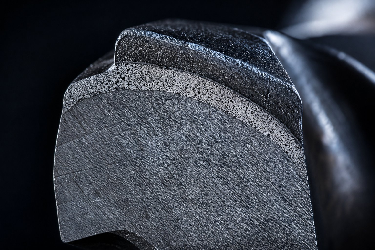
Nitrided alloy steel (4140 / 38CrMoAlA) sits at the foundation. This is the workhorse of the industry — accounting for roughly 80 percent of extruder screws and barrels in service worldwide. The steel is first quenched and tempered to a core hardness of 28-32 HRC for toughness, then gas or ion nitrided to form a surface layer reaching HV 900-1020 (approximately HRC 57-65). Aluminum in the alloy combines with nitrogen during nitriding to form extremely hard aluminum nitride compounds at the surface.
Here's the catch: that hardened layer is only about 0.5 to 0.8 mm thick. For non-abrasive commodity polymers like PE, PP, PS, and standard ABS, this thin armor provides excellent dimensional stability and cost-effectiveness. But once abrasive fillers or corrosive compounds wear through it, the softer core underneath erodes rapidly — and the screw is typically scrapped rather than repaired.
Through-hardened tool steels occupy the next tier. Conventional grades like D2 and H13 achieve HRC 58-62 through heat treatment, delivering wear resistance that extends through the entire cross-section rather than just a thin surface layer. Unlike nitrided screws, a tool steel screw doesn't suddenly lose its protective armor after a few tenths of a millimeter of wear — the hardness is consistent from the flight tip all the way to the root.
Powdered metallurgy (CPM) steels represent the top of the hierarchy. Manufactured using Hot Isostatic Pressing technology, CPM steels achieve an extremely uniform distribution of alloy carbides that conventional casting simply cannot replicate. Three grades dominate high-performance screw applications:
- CPM 10V: The highest wear resistance in the powder metallurgy family, with extremely high vanadium and carbon content. Best suited for severe abrasive duty, though its toughness is relatively lower — making it vulnerable to fracture under extreme torque or impact loads.
- CPM 9V: Slightly reduced vanadium and carbon content compared to 10V, significantly improving toughness while maintaining outstanding abrasion resistance. This grade has become the industry standard for high-performance extrusion and injection molding screws processing 30-50 percent glass-fiber reinforced engineering resins.
- CPM S90V: A high-chromium variant that matches CPM 9V's wear resistance while adding corrosion resistance comparable to 400-series stainless steel — valuable when both abrasion and chemical attack are present simultaneously.
The trade-off is cost. CPM screws typically run three to four times the price of a nitrided equivalent. But for lines processing highly filled engineering plastics, the math works in their favor: a CPM screw that lasts four to five replacement cycles of a nitrided screw saves far more in avoided downtime and changeover labor than the upfront premium.
Bimetallic and Carbide Solutions for Abrasive Polymers
What if you could keep the tough, ductile core of an alloy steel screw but give it a much thicker wear-resistant skin than nitriding alone can provide? That's the principle behind bimetallic construction — and it applies to both extruder barrels and screws.
A bimetallic barrel starts with a structural steel shell. A wear-resistant alloy liner — typically 1.5 to 2.5 mm thick, more than three times the depth of a nitrided layer — is centrifugally cast inside the bore and metallurgically bonded to the backing steel. The liner alloy is selected from three families based on the primary threat:
- Iron-based (Fe-Cr-B class), ~950-1,100 HV: The economical default for general abrasive duty on neutral polymers. Roughly three times the service life of nitrided extrusion barrels at moderate additional cost.
- Nickel-based (Ni-Cr class), ~950-1,100 HV with superior chemistry: Specified when corrosion is the primary threat — fluoropolymers, halogenated flame retardants, PVC, and high-temperature resins like PEEK and PPS that attack iron-based alloys.
- Tungsten-carbide-bearing matrices: The premium anti-wear grade for severe abrasion — 30 percent or higher glass fiber loading, heavy mineral filler content, and abrasive recycled streams.
On the screw side, bimetallic construction takes two forms. Full-coverage spray welding applies a Ni60-class alloy across the entire flight surface — appropriate when corrosion or whole-surface abrasion threatens the screw body. Hardfaced flight tips apply tungsten carbide or similar alloys only to the outermost edges of the flights, where metal-to-metal contact with the barrel wall concentrates wear. As bimetallic engineering references emphasize, the barrel liner and screw surface wear against each other as a matched pair — specifying a carbide-grade barrel against a plain nitrided screw simply relocates the wear to the cheaper component, and the flight clearance opens just the same.
For processors running glass-filled or mineral-filled resins, carbide-tipped flights are a practical intermediate step between fully nitrided screws and solid tool steel. Brazed or welded carbide inserts on the flight lands resist the cutting action of hard fillers far longer than even bimetallic coatings, extending service intervals without the cost of a solid CPM screw.
Specialized surface coatings add another layer of protection — literally. Hard chrome plating has long been the go-to for corrosion resistance when processing fluoropolymers and other chemically aggressive resins. However, as industry reporting on wear technology notes, tightening REACH regulations on hexavalent chromium (Chrome-6) have pushed processors toward alternatives. PVD (Physical Vapor Deposition) coatings like Oerlikon Balzers' Balinit Croma Plus offer combined wear and corrosion protection in a chrome-nickel-based multilayer system that is harder than hard chrome, highly oxidation-resistant, and free of Chrome-6 regulatory concerns. PVD-coated screws also benefit from improved surface smoothness, which promotes better material flow, faster color changes, and reduced deposit buildup.
| Material / Coating Type | Typical Hardness Range | Wear Resistance Rating | Corrosion Resistance Rating | Recommended Polymer Applications |
|---|---|---|---|---|
| Nitrided 4140 / 38CrMoAlA | HV 900-1020 (surface); HRC 28-32 (core) | Moderate | Fair | Unfilled PE, PP, PS, ABS, and other commodity resins with stable formulations |
| Bimetallic — Iron-Based Liner | HV 950-1,100 | Excellent | Fair to Good | WPC, SPC, high-calcium compounds, moderately filled polyolefins, recycled streams |
| Bimetallic — Nickel-Based Liner | HV 950-1,100 | Good to Excellent | Excellent | PVC, fluoropolymers, halogenated flame-retardant compounds, PEEK, PPS |
| Bimetallic — Tungsten Carbide Matrix | Highest effective hardness | Outstanding | Good | 30%+ glass fiber reinforced resins, heavy mineral filler loading, severely abrasive recycled plastics |
| Through-Hardened Tool Steel (D2 / H13) | HRC 58-62 | Very Good (through entire cross-section) | Fair | Moderately to highly filled engineering resins; applications requiring uniform hardness through the screw body |
| CPM Powder Metallurgy (9V / 10V / S90V) | HRC 54-62 (maintained at elevated temps) | Outstanding | Good to Excellent (S90V) | 30-50% glass-fiber reinforced PA, PBT, PET; extreme abrasive duty where screw root erosion is the failure mode |
| Hard Chrome Plating | HV 850-1000 | Moderate | Very Good | Fluoropolymers, corrosive resins; declining due to REACH restrictions on Chrome-6 |
| PVD Coating (e.g., Balinit Croma Plus) | Higher than hard chrome | Very Good | Very Good | Elastomers, flame-retardant compounds, pigmented resins, applications with frequent color changes |
The practical sourcing implication of this material hierarchy is straightforward: processors need a supplier whose catalog spans the full range. Suppliers like NANHAIYA offer extruder screws and barrels in multiple metallurgical configurations — from standard nitrided steel through bimetallic and tool steel options — enabling processors to match material selection precisely to their polymer, filler type, and production volume without switching vendors for each tier of the specification. That flexibility simplifies procurement and ensures the screw and barrel arrive as a metallurgically matched pair, which is essential for maximizing the service life of both components.
Selecting the right metallurgy keeps your screw geometry intact longer — but geometry itself must be tailored to the specific polymer flowing through the barrel. A screw built from the finest CPM steel will still underperform if its compression ratio, L/D, and shear profile don't match the rheological demands of the resin it's processing.
Matching Plastic Extruder Screw Geometry to Polymer Families
Every polymer melts differently. Some undergo a sharp solid-to-liquid transition at a defined temperature. Others soften gradually over a wide range. Some release corrosive gases under shear. Others absorb moisture that must be driven off mid-process. These rheological and thermal characteristics aren't minor footnotes — they dictate which compression ratio, L/D ratio, and screw architecture will produce a stable, defect-free melt versus one plagued by degradation, surging, or unmelted solids.
Yet many processors still run a single "universal" screw across multiple resin families, accepting mediocre results as normal. The reality? A plastic extruder screw optimized for HDPE pipe can destroy a PVC profile. A design that handles polystyrene beautifully may leave nylon riddled with moisture-driven defects. Matching screw geometry to the specific polymer family isn't optional — it's the foundation of consistent output.
Polyolefins, Styrenics, and Commodity Resin Screw Design
Semi-crystalline polyolefins like HDPE and PP undergo a dramatic density change as their ordered crystalline regions collapse during melting. A kilogram of HDPE pellets occupies roughly 30 to 40 percent more volume than the same mass in molten form. That volume reduction must be accommodated by relatively high compression ratios — typically 3:1 to 4:1 for PE and 2.5:1 to 4:1 for PP — to compact the solid bed, expel trapped air, and generate enough shear energy to complete the melting process. Moderate L/D ratios of 24:1 to 28:1 provide sufficient residence time for these materials without risking thermal degradation, since polyolefins tolerate a relatively wide processing temperature window.
Amorphous styrenics like PS and ABS behave quite differently. Without a crystalline structure to break down, they soften progressively rather than melting at a sharp transition point. This gentler melting behavior means lower compression ratios are acceptable — around 2:1 to 4:1 for PS and 1.6:1 to 2.5:1 for ABS. Overly aggressive compression on ABS, in particular, generates excessive shear heat that degrades the butadiene rubber phase responsible for impact strength. A screw plastic extruder setup for ABS should favor a gradual transition zone rather than a steep compression taper.
For general commodity processing where material changeovers are frequent, a general-purpose screw with a moderate compression ratio around 2.5:1 to 3:1 and a 24:1 L/D serves as a reasonable compromise — accepting slightly suboptimal performance on any single resin in exchange for acceptable versatility across the commodity spectrum.
Engineering Resins, PVC, and Shear-Sensitive Polymers
Engineering polymers demand far more precision in screw selection, and the consequences of mismatching are far more severe.
PVC stands in a category of its own. This material is extremely sensitive to both shear and thermal history — processing temperatures sit dangerously close to the decomposition threshold. Over-compressing PVC triggers thermal degradation that releases hydrochloric acid gas, which not only ruins the product but actively corrodes the extrusion screw barrel and every downstream component it contacts. PVC screws require low compression ratios of approximately 1.5:1 to 2:1 with gentle, extended transition zones that avoid localized shear spikes. As noted in screw design engineering references, shorter L/D ratios are generally preferred for PVC to minimize residence time and the associated risk of thermal degradation. Corrosion-resistant metallurgy — nickel-based bimetallic liners or chrome-plated surfaces — is equally essential.
Nylon (PA6, PA66) and other hygroscopic engineering resins present a different challenge. These polymers absorb atmospheric moisture that causes hydrolytic degradation during processing — chain scission that reduces molecular weight and mechanical properties. Vented screw designs with longer L/D ratios of 30:1 or greater allow moisture to be extracted through a barrel vent port during processing, reducing or eliminating the need for extended pre-drying cycles. The compression ratios for nylon run relatively high — around 3:1 to 3.7:1 — reflecting the significant energy needed to melt a strongly crystalline polymer.
PEEK and high-temperature semi-crystalline resins push every aspect of the system to its limits. Processing temperatures can exceed 400 degrees Celsius, demanding not only high-performance metallurgy (CPM tool steels or nickel-based alloys) but also precise thermal control across all barrel zones. Compression ratios of 2.5:1 to 3:1 combined with L/D ratios of 28:1 to 32:1 are typical, with barrel heating capacity sized to deliver the elevated temperatures needed without relying excessively on shear heating that could cause localized overheating.
TPU and thermoplastic elastomers need the opposite approach — low-shear screw designs that prevent viscous overheating. These materials have high melt viscosity and are prone to temperature-induced degradation that manifests as surface defects, discoloration, and loss of elastic recovery. Low compression ratios around 2:1 to 2.5:1, deeper metering channels, and the avoidance of dispersive mixing elements protect the material from excessive energy input.
| Polymer Family | Recommended Compression Ratio Range | Suggested L/D Ratio | Shear Sensitivity Level | Special Design Considerations |
|---|---|---|---|---|
| PE (HDPE, LDPE, LLDPE) | 3:1 to 4:1 | 24:1 to 28:1 | Low | Grooved feed throat improves conveying of slippery pellets; barrier screw designs recommended for high-output film lines |
| PP (Homopolymer, Copolymer) | 2.5:1 to 4:1 | 24:1 to 28:1 | Low to Moderate | Wide processing window; general-purpose screws acceptable for most applications |
| PS (GPPS, HIPS) | 2:1 to 4:1 | 22:1 to 26:1 | Low to Moderate | Amorphous — melts gradually; moderate compression adequate |
| ABS | 1.6:1 to 2.5:1 | 22:1 to 26:1 | Moderate | Excessive shear damages rubber phase; gradual transition zone preferred |
| PVC (Rigid and Flexible) | 1.5:1 to 2:1 (granules); up to 3:1 (powder) | 18:1 to 22:1 | Very High | Corrosion-resistant metallurgy mandatory; gentle transition zone; short residence time critical to avoid HCl release |
| PA (Nylon 6, 66, 1010) | 3:1 to 3.7:1 | 30:1+ | Low to Moderate | Vented screw designs recommended for moisture removal; pre-drying still advisable for critical applications |
| PC (Polycarbonate) | 2.5:1 to 3:1 | 24:1 to 28:1 | Moderate to High | High viscosity requires strong shear mixing zones; optical applications demand air-free melt |
| PET (Polyethylene Terephthalate) | 3:1 to 3.5:1 | 28:1 to 30:1 | Moderate | Extremely moisture-sensitive — vented or thoroughly pre-dried; hydrolysis degrades IV rapidly |
| POM (Acetal) | 2.8:1 to 4:1 | 22:1 to 26:1 | Moderate to High | Releases formaldehyde at degradation temperatures; avoid dead zones and excessive residence time |
| PEEK / PPS (High-Temp Semi-Crystalline) | 2.5:1 to 3:1 | 28:1 to 32:1 | Moderate | Processing above 400 degrees C; high-performance metallurgy (CPM steel or nickel alloy) required; precise thermal control essential |
| TPU / Thermoplastic Elastomers | 2:1 to 2.5:1 | 24:1 to 28:1 | High | Low-shear design with deeper metering channels; avoid dispersive mixing elements to prevent overheating |
This table is a starting framework — not a set of rigid rules. Actual screw specifications depend on the specific grade within each polymer family, the filler or additive package, the target throughput, and the machine platform. A 30 percent glass-filled PA66 compound, for example, needs wear-resistant metallurgy on top of the geometry recommendations for unfilled nylon. A recycled PET stream may demand both a vented extrusion screw barrel configuration and more aggressive compression to handle variable bulk density.
The critical principle is this: screw geometry must follow polymer behavior. Every polymer family has a specific melting mechanism, a thermal stability window, and a shear tolerance threshold. Ignoring any of these properties in screw selection creates processing problems that no amount of RPM adjustment or temperature tweaking can fully correct — which raises the question of how screw speed and back pressure interact with geometry to define the available operating window.
Screw Speed, Back Pressure, and Output Quality
Screw geometry sets the ceiling on what a processing line can achieve. But within that ceiling, two operator-controlled variables — screw speed and back pressure — determine where the process actually operates. Crank the RPM too high, and the polymer overheats. Set back pressure too low, and the melt arrives at the die riddled with air pockets and inconsistent density. Finding the productive sweet spot between these two forces is where theory meets the production floor — and where a well-designed screw and barrel combination separates itself from a poorly matched one.
How Screw Speed Affects Shear Heating and Residence Time
Increasing screw speed does two things simultaneously: it raises throughput and it increases viscous shear heating in the melt. These effects are inseparable. As the screw rotates faster, the velocity gradient between the moving flight and the stationary extrusion barrel wall steepens. Polymer trapped in that gradient experiences more intense internal friction — and that friction converts directly into heat. In many processing setups, 70 to 90 percent of the energy needed to melt the plastic comes from the screw's mechanical work rather than from barrel heater bands.
Here's where things get tricky. That shear-generated heat isn't uniformly distributed. It concentrates near the barrel wall and along the flight clearance zone — the narrow gap where the flight land slides past the barrel bore. The result is localized hot spots that can exceed the polymer's thermal stability window even when the average melt temperature reads safely within spec. For shear-sensitive resins like PVC or ABS, those hidden hot spots trigger degradation that shows up as discoloration, reduced impact strength, or corrosive acid release — defects that may not be visible until parts reach quality inspection or, worse, the end customer.
Faster rotation also reduces residence time. Every pellet spends less time inside the barrel, which sounds efficient until you consider what shorter residence time actually means for melting and mixing. Research on screw temperature profiles confirms this dynamic: as screw speed increases from 30 to 60 to 90 RPM, unmelted solids travel farther downstream before completing the melting process. At 30 RPM, solids may finish melting around 15 diameters along the screw length. Push that to 90 RPM, and the solid bed extends to 17 or 18 diameters — perilously close to the metering zone. If the screw's flighted length doesn't provide enough margin, unmelted particles survive into the discharge and contaminate the final product.
This sets up a fundamental tension. Processors want higher RPM for greater output. But the screw's geometry — its L/D ratio, compression zone length, and melting capacity — imposes a hard limit on how fast you can spin before melting becomes incomplete or shear heating becomes destructive. Barrier screw designs push that limit higher by accelerating the melting process. A general-purpose three-zone screw hits it sooner.
In theory, extrusion operates somewhere on a spectrum between two extremes. Isothermal operation is the ideal — barrel heaters supply all the thermal energy, and the screw turns slowly enough that viscous dissipation is negligible. Melt temperature stays precisely at the setpoint. Adiabatic operation is the opposite extreme — the screw spins fast enough that shear heating alone generates more energy than needed, and barrel cooling struggles to remove the excess. Melt temperature climbs above the setpoint no matter what the heater controllers do. Real-world processing falls between these poles, but high-speed production lines lean toward the adiabatic end — making screw geometry the primary thermal control mechanism rather than barrel temperature settings.
Balancing Back Pressure, Melt Homogeneity, and Output Rate
Back pressure is the resistance to forward flow created by the die, screen pack, breaker plate, or — in injection molding — the hydraulic force applied against the back of the screw during recovery. Imagine pushing a loaded cart downhill: without some braking force opposing the descent, the load crashes uncontrollably to the bottom. Back pressure serves that braking role, ensuring the screw retreats in a controlled manner and the melt packs consistently ahead of the screw tip.
Higher back pressure increases the melt's residence time inside the screw channels. Material lingers longer in the compression and metering zones, receiving additional shear mixing and thermal homogenization. This is particularly valuable for injection molding screws and barrels, where shot-to-shot consistency depends on uniform melt density. Backpressure optimization studies demonstrate this clearly: weighing fill-only shots at progressively higher back pressure settings reveals a point where shot-weight variation drops to its minimum — the melt density has become consistent enough that every shot delivers the same mass of polymer into the mold.
But the trade-off is real. Higher back pressure pushes more melt backward through the screw channels — increasing the pressure flow component that opposes the forward drag flow. Net throughput drops. In extrusion, this means fewer pounds per hour through the die. In injection molding, it extends recovery time and can limit cycle time. Push back pressure too far, and you also risk thermally degrading the polymer through extended shear exposure, especially with heat-sensitive materials.
The practical implications come down to finding an operating window — the range of screw speed and back pressure combinations that simultaneously produce acceptable melt temperature, stable pressure at the die, adequate mixing, and the target output rate. Operators on the floor adjust these two variables constantly, sometimes without realizing that screw geometry is the invisible third variable constraining their options.
Screw design determines the width of the processing window. A well-matched screw offers broad latitude for adjusting speed and back pressure without sacrificing melt quality, while a poorly matched screw forces operators into a narrow, fragile set of conditions where even small deviations cause defects.
Consider two scenarios. A barrier screw with optimized compression ratio and a Maddock mixing section can run at higher RPM because its enhanced melting capacity keeps solids out of the metering zone even at elevated throughput. It tolerates moderate back pressure reductions without losing melt homogeneity because the dispersive mixer already ensures consistent temperature and composition. The operating window is wide — the operator has room to adjust.
A mismatched general-purpose screw running the same polymer on the same machine has none of that margin. Increase RPM by 10 percent, and unmelted particles appear in the product. Reduce back pressure slightly, and shot weight starts drifting. The operator is trapped in a razor-thin band of acceptable settings, and any upstream disturbance — a batch-to-batch resin variation, a worn flight clearance, a slight hopper bridging event — pushes the process outside that band and into scrap production.
This is why screw geometry, speed, and back pressure cannot be treated as independent decisions. They interact as a system. And the single fastest way to widen a frustratingly narrow processing window isn't to retrain operators or invest in tighter process controls — it's to re-examine whether the screw's design actually matches the polymer and the throughput target. When the geometry is right, stable processing follows naturally. When it's wrong, every shift becomes a firefight — and the wear patterns that accumulate under those stressed conditions accelerate the timeline toward the next critical decision: when to pull the screw and replace it.
Screw Wear, Maintenance, and Replacement Strategy
Every extruder screw begins degrading the moment it starts rotating inside the barrel. That's not alarmism — it's metallurgical reality. The flight lands slide against the barrel bore under loads exceeding 1,500 PSI at temperatures between 200 and 300 degrees Celsius, while abrasive fillers, corrosive byproducts, and cyclic thermal stress attack every exposed surface. Industry data suggests that 85 percent of extruders experience barrel and screw wear issues during their service life. The question isn't whether wear will happen — it's whether you'll detect it early enough to plan a cost-effective response or late enough that it forces an emergency shutdown.
Identifying Wear Mechanisms and Patterns
Four distinct mechanisms attack the screw's precision surfaces, and each one leaves a different forensic signature.
Adhesive wear occurs when the screw flight land and the barrel wall make direct metal-to-metal contact. Momentary micro-welds form and then fracture, tearing material from one or both surfaces. You'll recognize it by a rolled-over burr on the trailing edge of the flight land, scoring marks along the barrel bore, or hardfacing material visibly missing from the flight tips. Poor barrel alignment, screw deflection from solids wedging, or a worn thrust bearing that allows axial play can all drive this mechanism. As Jeff Kuhman of Glycon Corp. has documented, even a properly designed screw installed in a misaligned barrel will gall — making alignment checks mandatory during any changeout.
Abrasive wear is the most common culprit, accounting for roughly 50 percent of all wear cases. Glass fibers, mineral fillers like calcium carbonate and talc, recycled-stream contaminants, and even metallic tramp particles from upstream equipment grind away at the flight lands and channel root. Abrasive wear rates typically run 0.05 to 0.15 mm per 1,000 operating hours — fast enough that a screw processing 30 percent glass-filled nylon on a Davis-Standard extruder or similar high-output platform can lose its critical flight clearance within a single production year.
Corrosive wear attacks the metal's chemistry rather than its surface. PVC releases hydrochloric acid gas during processing. Flame-retardant compounds generate halogenated acids. Fluoropolymers produce hydrofluoric acid at degradation temperatures. Each of these agents dissolves the iron matrix of standard steel, weakening the surface so that even mild mechanical contact removes material. Corrosion rates of 0.01 to 0.05 mm per 1,000 hours may seem modest, but they compound relentlessly — and the damage is often hidden beneath a layer of polymer residue until the screw is pulled for inspection.
Fatigue wear is the quietest killer. Repeated thermal cycling — heating during production, cooling during shutdowns — induces micro-cracking on the screw surface. Over thousands of cycles, these cracks propagate and small chips spall off, particularly at stress concentration points like the flight-to-root transition. Fatigue wear contributes only about 5 percent of total wear, but its onset is nearly invisible without magnification, and the failures it eventually causes are sudden and destructive.
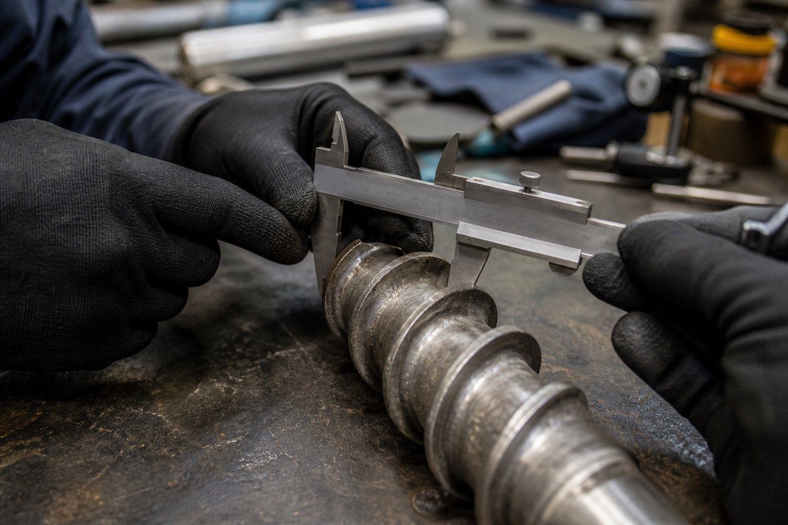
Identifying which mechanism dominates your application requires both visual inspection and dimensional measurement. Three critical measurements tell the story:
- Flight outside diameter: Measured at multiple points along the screw length with precision calipers. Compare to the original OEM dimension — the new flight clearance is typically the nominal screw diameter divided by 1,000. For example, a 3.5-inch Davis standard extruder screw starts life with roughly 0.004 inches of clearance per side.
- Flight clearance (radial gap): This is the single most consequential wear indicator. When clearance exceeds approximately 0.15 mm, leakage flow over the flights increases dramatically, output efficiency drops, and melt temperature rises at constant RPM. As Spalding and Womer's extrusion research demonstrates, a screw with 0.011 inches of wear running PE at 150 kg/hr can push discharge temperatures up by 10 degrees Celsius — enough to make blown film operation unviable and force a rate reduction of 13 percent or more.
- Channel depth at the screw root: Root wear greater than 0.10 mm indicates material loss from the screw body itself — typically caused by abrasive fillers eroding the root surface in the rear of the channel where solid particles concentrate before wetting with molten polymer.
One commonly cited rule of thumb says to replace the screw when flight clearance reaches four times the original value. But that guideline oversimplifies the decision. A noncritical application like corrugated pipe can tolerate significantly higher wear levels, while a medical extrusion line may require replacement at just two times original clearance. The best trigger is economic: replace when the cost of declining output, rising energy consumption, and increasing scrap exceeds the cost of a new or refurbished screw.
Maintenance Planning and Sourcing Replacement Components
Reactive maintenance — waiting for output to collapse before pulling the screw — is the most expensive strategy a plant can adopt. Emergency replacements carry rush manufacturing premiums, unplanned downtime disrupts production schedules, and operating a severely worn screw in the interim accelerates barrel wear that multiplies the final repair bill. A structured preventive approach eliminates most of that cost.
Start by establishing baseline dimensional measurements at installation. Record the flight OD, channel depth at three points per zone, and barrel bore diameter at corresponding locations. These numbers become your reference standard — every subsequent inspection compares against them to quantify cumulative wear.
Schedule periodic inspections based on your application's severity. For unfilled commodity polymers on a standard nitrided screw, quarterly checks and an annual pull-and-measure cycle are typically sufficient. For glass-filled engineering resins, inspect every 2,000 operating hours — roughly quarterly on a two-shift operation. For highly abrasive recycled streams, monthly visual assessments combined with output-rate trending provide the earliest warning.
Between physical inspections, track process data as a proxy for wear progression. The following warning signs reliably indicate that a barrel and screw set is approaching its replacement threshold:
- Declining specific output rate — the ratio of throughput (lb/hr) to screw speed (RPM) drops as leakage flow over worn flights steals from net forward conveyance.
- Increasing melt temperature at constant RPM — worn clearances reduce the heat-transfer coefficient at the barrel wall, trapping more shear heat in the melt.
- Visible flight wear — hardfacing material worn through to base metal, rolled flight edges, or scoring marks on the barrel bore visible during screw pulls.
- Output surging — pressure fluctuations at the die caused by inconsistent melting or unstable solid conveying as worn flights lose their sealing function.
- Poor melt homogeneity — unmelted particles, color streaks, or temperature variation across the melt stream that worsens progressively over time.
- Rising motor current at constant screw speed — an increase exceeding 15 percent above baseline suggests mechanical interference, misalignment, or compensatory speed increases masking wear.
Keep a spare screw in storage so that when the current screw reaches end of life, the changeover happens in hours rather than weeks. As industry experts recommend, a worn screw can be refurbished — re-hardfaced and re-machined to original dimensions — but should not be refurbished more than three times. Each re-welding cycle degrades the base metal, increasing the risk of hardfacing delamination during operation. After three rebuilds, replacement with a new screw is the only reliable option.
When the barrel is exposed during a screw pull, measure its bore diameter as well. An iron-based bimetallic barrel liner typically lasts about three screw lifetimes, but this ratio shifts dramatically with abrasive or corrosive polymers. Replacing only the screw while leaving a worn barrel in service simply transfers the clearance problem to the new component — the oversized bore restores the excessive flight clearance that caused the original performance decline.
When replacement is necessary, sourcing from a manufacturer that offers matched screw and barrel sets — engineered to OEM specifications across the full range of metallurgies covered earlier in this article — streamlines the procurement process and ensures dimensional compatibility. NANHAIYA, for example, provides a full catalog of extruder screws and barrels for both extrusion and injection molding applications, spanning nitrided steel through bimetallic and tool steel configurations. Ordering matched pairs from a single source eliminates the risk of incompatible alloys wearing against each other and guarantees that the new barrel and screw arrive with flight clearances set to the tight tolerances that restore original processing performance.
Ultimately, screw wear is inevitable — but unplanned downtime is not. A disciplined maintenance framework that combines baseline measurement, periodic inspection, process-data trending, and proactive sourcing transforms screw replacement from an emergency expense into a scheduled, budgetable event. The processors who treat their extruder screws as precision instruments — monitoring them with the same rigor they apply to mold tooling or die geometry — consistently achieve the lowest cost-per-kilogram and the highest uptime across their production floors.
Frequently Asked Questions About Extruder Screws
1. What is the difference between a barrier screw and a general-purpose extruder screw?
A general-purpose extruder screw uses a single helical flight across three zones — feed, compression, and metering — making it cost-effective and versatile for commodity resins. A barrier screw adds a secondary flight in the transition zone that physically separates the solid bed from the melt pool, forcing all material to fully melt before reaching the metering section. Barrier designs like the Maillefer and Barr types deliver superior output stability, eliminate unmelted particles, and support higher throughput rates, but they cost more and are less forgiving when switching between different resin types. Processors typically upgrade to barrier screws when output surging, unmelted solids, or melt temperature inconsistency limits their production quality. Suppliers such as NANHAIYA offer both general-purpose and barrier screw configurations engineered to match specific polymer and throughput requirements.
2. How do I know when an extruder screw needs to be replaced?
Several measurable indicators signal that an extruder screw is approaching end of life. The most reliable metric is flight clearance — when the radial gap between the flight land and barrel wall exceeds roughly 0.15 mm or four times the original clearance, leakage flow increases significantly and output efficiency drops. Process-level warning signs include declining specific output rate (lb/hr per RPM), rising melt temperature at constant screw speed, visible flight wear or scoring, output surging at the die, poor melt homogeneity such as color streaks or unmelted particles, and motor current increases exceeding 15 percent above baseline. Establishing baseline dimensional measurements at installation and scheduling periodic inspections based on material abrasiveness enables proactive replacement planning rather than costly emergency shutdowns.
3. What compression ratio should I use for PVC extrusion screws?
PVC requires low compression ratios — typically 1.5:1 to 2:1 for granule feed and up to 3:1 for powder feed — with gentle, extended transition zones. This conservative geometry is essential because PVC processing temperatures sit dangerously close to the material's decomposition threshold. Over-compressing PVC generates excessive shear heat that triggers thermal degradation and releases hydrochloric acid gas, which damages the finished product and actively corrodes the screw, barrel, and downstream equipment. Beyond geometry, PVC screws also require corrosion-resistant metallurgy such as nickel-based bimetallic liners or chrome-plated surfaces. Shorter L/D ratios of 18:1 to 22:1 further minimize residence time and reduce degradation risk.
4. What is the L/D ratio of an extruder screw and why does it matter?
The L/D ratio is the screw's flighted length divided by its nominal diameter. It represents the total processing length available for conveying, melting, mixing, and pressurizing polymer. Shorter L/D ratios like 20:1 suit simple commodity resins with narrow melting ranges, while longer ratios of 30:1 to 36:1 provide the extended residence time and mixing length that engineering resins and filled compounds require for thorough melting and homogenization. Twin screw compounders often use even longer L/D ratios of 32:1 to 48:1 to accommodate multiple functional zones including melting, mixing, venting, and pressure building. Choosing an insufficient L/D ratio leads to incomplete melting, poor mixing, and unmelted solids contaminating the final product.
5. What screw and barrel materials are best for processing glass-filled resins?
Glass-filled resins are highly abrasive, so standard nitrided steel screws wear through their thin hardened surface layer quickly — sometimes within a single production year. For moderate glass loading (10-20 percent), through-hardened tool steels like D2 or H13 provide wear resistance throughout the entire screw cross-section. For 30 percent or higher glass fiber content, CPM powder metallurgy steels such as CPM 9V offer outstanding abrasion resistance with superior toughness. On the barrel side, tungsten carbide matrix bimetallic liners deliver the best protection against severe abrasive wear. Critically, the screw and barrel must be specified as a metallurgically matched pair — pairing a carbide-grade barrel with a plain nitrided screw simply shifts all the wear to the softer component. NANHAIYA offers matched screw and barrel sets across the full metallurgical range, from nitrided steel through bimetallic and CPM tool steel configurations.
Written by
Nanhaiya Technical Team
Zhoushan Nanhaiya Plastic Machinery Co., Ltd.
The Nanhaiya technical team supports screw and barrel manufacturing projects through application review, technical communication, custom manufacturing coordination, and production and quality control.
Discuss Your Application
Related Articles
More insights on screw barrel technology and plastics processing.
PVC Pipe Making Machine: What No Supplier Will Tell You First
Oct 21, 2026
Learn what a PVC pipe making machine really includes, how each component works, extruder types compared, maintenance schedules, defect fixes, and buying tips.
Read Article
What Your Film Extrusion Machine Datasheet Won't Tell You
Oct 20, 2026
Film extrusion machine guide covering blown vs cast processes, multilayer configurations, screw specs, resin selection, and supplier evaluation for production engineers.
Read Article
Raw Scrap to Perfect Pellets: Plastic Pelletizing Machine Guide
Oct 19, 2026
Learn how a plastic pelletizing machine converts scrap into uniform pellets. Covers cutting methods, extruder types, quality control, costs, and maintenance.
Read ArticleLooking for something else?
Search by material, symptom or product and jump straight to the relevant page.
These are navigation suggestions based on keyword matching — not a quotation, not a delivery commitment, and not a substitute for engineering review. Final specification is confirmed by our engineers against your drawings and processed material.
Need help with screw barrel selection?
Share your machine model, processed material and application. Our team can help with pricing and technical support.