

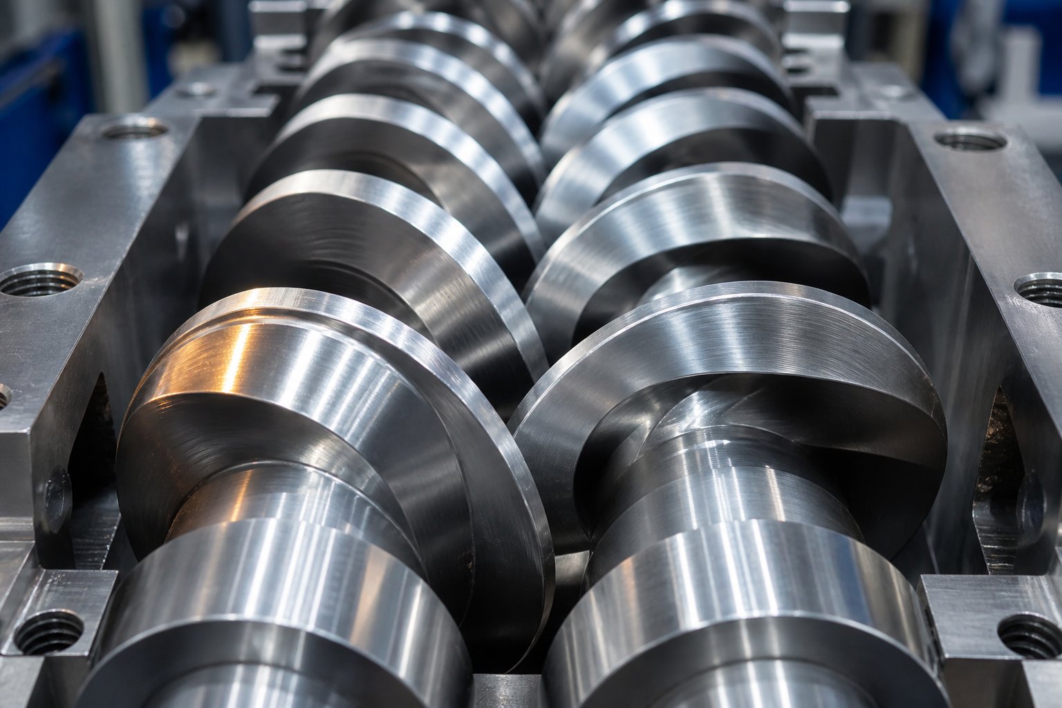
Why Twin Screw Extruder Design Calculations Matter for Every Extrusion Engineer
Imagine standing in front of a twin screw extruder that's underperforming. Throughput is 20% below target, torque is spiking unpredictably, and the melt temperature keeps creeping past spec. You could start swapping screw elements by trial and error - or you could run three calculations in under ten minutes and pinpoint the root cause. That's the power of twin screw extruder design calculations: the mathematical framework engineers use to specify screw geometry, predict throughput, estimate power consumption, and optimize processing conditions before a single pellet hits the barrel.
These calculations sit at the intersection of polymer science theory and real-world machine performance. They translate material properties and process goals into concrete engineering parameters - channel depths, flight clearances, torque limits, and shear rate profiles that determine whether a screw configuration succeeds or fails. For twin screw extruders running across plastics compounding, pharmaceutical hot-melt extrusion, and food processing, the underlying math is remarkably consistent. The formulas don't change just because the material does.
Yet here's the problem: no single resource currently brings all the core formulas together. Throughput equations live in one textbook. Torque calculations appear in an OEM's technical bulletin. Shear rate approximations surface in a conference paper. Engineers piece together fragments from scattered sources, often missing critical relationships between parameters. This article closes that gap with an engineering handbook approach - every essential formula in one place, with the context you need to actually use them.
What Twin Screw Extruder Design Calculations Actually Determine
The scope of these calculations covers every major decision point in screw extrusion design and optimization. Specifically, this article addresses:
- Screw geometry parameters - pitch, helix angle, channel depth, flight width, and flight clearance
- Critical design ratios - Do/Di (outer-to-inner diameter) and L/D (length-to-diameter) relationships
- Flow and throughput equations - drag flow, pressure flow, and leakage flow components
- Energy and torque requirements - specific mechanical energy, specific thermal energy, and motor sizing
- Shear rate profiles - apparent shear rates across conveying elements and kneading blocks
- Fill factor estimations - degree of fill in starve-fed processing zones
Each category feeds into the next. You can't calculate throughput without geometry, and you can't estimate power consumption without throughput. The math forms a chain, and a weak link anywhere compromises the entire design.
Who Needs These Calculations and When
Three groups rely on these formulas most heavily. Extrusion engineers specifying new screws use them to define geometry from scratch. Machine rebuilders optimizing existing twin screw extruders use them to diagnose why a current configuration underperforms. And production teams scaling processes - moving from a 27 mm lab extruder to a 75 mm production line, for instance - depend on them to predict whether a proven recipe will translate at scale. Industry experts have noted that understanding extruder basics and applying simple formulas can mean the difference between success and failure for a manufacturing operation.
Engineers who master fundamental twin screw extrusion equations develop a diagnostic intuition that simulation software alone cannot provide - the ability to glance at a torque readout or a specific energy value and immediately know what's wrong and why.
Simulation tools are powerful, but they're black boxes without this foundation. Hand calculations give you the intuition to question a simulation's output, catch input errors, and make rapid decisions on the production floor where there's no time to build a new model. They're also the fastest way to sanity-check a quoted screw design before committing capital.
Every formula that follows builds on the geometry of the screw itself - the dimensions and proportions that physically define how material moves, melts, and mixes inside the barrel.
Screw Geometry Calculations from Pitch to Flight Clearance
Every throughput prediction, torque estimate, and shear rate profile you'll ever calculate for an extruder twin screw system traces back to a handful of geometric dimensions. Get these numbers right, and the downstream math falls into place. Get them wrong - even slightly - and every subsequent formula inherits the error. These are the foundational parameters that physically define how material is conveyed, compressed, and mixed inside the barrel of any twin-screw extruder machine.
Pitch and Helix Angle Formulas
Pitch (P) is the axial distance between two consecutive flights on the same screw thread. Think of it as the "stride length" of the screw - it determines how much material advances per revolution. For a single-start (single-flight) screw element, the pitch equals the lead (L). For multi-start screws, the relationship is:
L = P x ns
where ns is the number of starts (threads). A twin-screw conveying element labeled "SE-30/30 R," for example, indicates a 30 mm pitch over a 30 mm segment length, with right-hand rotation - a nomenclature system detailed by NC State Extension for Erdmenger-profile screw elements. Increasing the pitch increases the conveying rate per revolution but reduces the number of flights per unit length, which shifts the balance away from pressure buildup and toward volumetric transport.
The helix angle (phi) quantifies this balance mathematically. It's the angle between the flight helix and a plane perpendicular to the screw axis:
phi = arctan(P / (pi x D))
where D is the outer screw diameter. A standard square-pitch screw (P = D) yields a helix angle of approximately 17.65 degrees. Shallow helix angles favor pressure generation; steeper angles boost conveying capacity at the expense of pressure development. You'll notice that most parallel twin screw extruder conveying elements use pitches between 0.5D and 1.5D, keeping the helix angle within a range that balances forward transport with adequate barrel filling.
Channel Depth and Flight Geometry
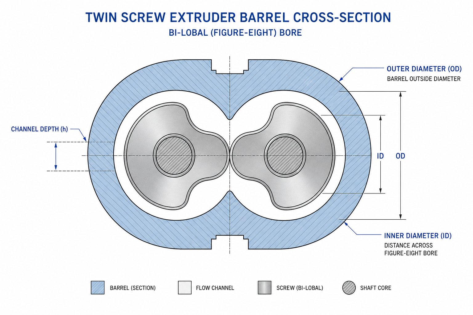
Channel depth (H) is the radial distance from the flight tip to the screw root - the space where material actually resides and flows. For a twin screw extruder, it's calculated directly from the outer diameter (Do) and inner (root) diameter (Di):
H = (Do - Di) / 2
Deeper channels mean higher free volume per unit length, allowing greater throughput capacity but reducing the shear rate imposed on the material. This is a critical trade-off that ripples through every formula covered later in this article.
Flight width (e) is the axial thickness of the screw flight at its tip. It's typically expressed as a fraction of screw diameter, with common values ranging from 0.08D to 0.12D for intermeshing twin screws. Wider flights reduce the available channel width (W), which limits cross-channel flow and conveying volume, but they provide structural strength to resist bending forces at high torque.
Flight clearance (delta) is the radial gap between the flight tip and the barrel wall. For self-wiping co-rotating twin screws, this clearance is intentionally tight - typically 0.002D to 0.003D - to maintain the self-cleaning action that defines Erdmenger geometry. Larger clearances increase leakage flow over the flight tips, directly reducing pumping efficiency. In practice, clearance also widens over time due to abrasive wear, which is why engineers factor wear allowances into initial design calculations.
The following table consolidates these core geometry parameters for quick reference:
| Parameter | Symbol | Formula | Typical Range | Engineering Significance |
|---|---|---|---|---|
| Pitch | P | P = L / ns | 0.5D to 1.5D | Sets conveying rate per revolution and residence time per element |
| Helix Angle | phi | phi = arctan(P / (pi x D)) | 9 to 25 degrees | Balances conveying efficiency against pressure generation capability |
| Channel Depth | H | H = (Do - Di) / 2 | 0.08D to 0.25D | Defines free volume, shear rate, and maximum throughput capacity |
| Flight Width | e | e = fraction of D | 0.08D to 0.12D | Affects available channel width, structural integrity, and wiping action |
| Flight Clearance | delta | delta = fraction of D | 0.002D to 0.003D | Controls leakage flow; tighter clearance improves pumping efficiency |
| Channel Width | W | W = (P x cos(phi)) - e | Varies with P and e | Determines cross-sectional flow area available for material transport |
| Number of Starts | ns | Design choice | 1 to 3 (typically 2) | Two-start (bi-lobal) is standard for co-rotating intermeshing screws |
How Geometry Parameters Interrelate
Here's where screw geometry gets interesting - and where many engineers trip up. These parameters are not independent variables you can adjust in isolation. They form an interlocked system where changing one dimension cascades through the rest.
Imagine you deepen the channel to increase free volume and boost throughput. That same deeper channel reduces the shear rate (since shear rate is inversely proportional to channel depth), which may compromise dispersive mixing. It also changes the velocity profile across the channel, affecting the drag flow component in the throughput equation. Simultaneously, the deeper cut reduces the screw root diameter, lowering the shaft's torsional stiffness and limiting the maximum torque the screw can transmit.
Adjusting pitch produces a different chain reaction. A longer pitch steepens the helix angle, increasing the axial velocity of material along the screw but reducing the cross-channel flow component that drives mixing. It also means fewer flights per unit length, which decreases the total wiping frequency and can affect residence time distribution in that zone.
Even flight clearance, which seems like a minor machining tolerance, has outsized effects. A clearance that grows from 0.002D to 0.005D through wear can increase over-flight leakage flow enough to measurably reduce net throughput and alter the pressure profile along the entire screw length.
The critical takeaway is that screw geometry choices cascade into every downstream calculation. Channel depth feeds directly into shear rate and drag flow formulas. Pitch drives conveying efficiency and residence time estimates. Flight clearance governs leakage flow corrections. Two key design ratios - the outer-to-inner diameter ratio (Do/Di) and the length-to-diameter ratio (L/D) - bundle many of these individual parameters into higher-level descriptors that define the fundamental capability of the entire machine.
Do/Di Ratio and L/D Ratio Calculations That Define Extruder Capability
Individual geometry parameters - channel depth, pitch, flight clearance - tell you what's happening at a single point along the screw. But two higher-level ratios tell you what the entire machine is capable of. The twin screw extruder diameter ratio (Do/Di) and the length-to-diameter ratio (L/D) are the architectural constants that define the machine's fundamental capacity for volume, torque, and processing complexity. Change either one, and you're working with a fundamentally different extruder - even if every other specification stays the same.
Do/Di Ratio and Its Impact on Free Volume and Torque
The Do/Di ratio - outer screw diameter divided by inner (root) screw diameter - governs two competing priorities: twin screw extruder free volume and torque-carrying capacity. A higher ratio means shallower channels relative to the screw diameter, which leaves more metal in the screw root and therefore more cross-sectional area for the torque-transmitting shaft. A lower ratio means deeper channels, which carve out more space for material but reduce the shaft's structural backbone.
Here's the trade-off in concrete terms. A Do/Di of 1.22 produces deep channels with high free volume per unit length - ideal for early-stage R&D or micro-batch sampling where low-volume screws accommodate limited batch processing. At the opposite end, a Do/Di of 1.71 yields shallow channels with significantly less free volume but far greater torque density, which is essential when processing high-viscosity engineering thermoplastics that demand serious mechanical energy input.
The free volume per unit of L/D (often expressed in cc/diameter) can be approximated as a function of Do/Di using the cross-sectional area relationship:
Vfree per L/D ~ (pi / 4) x Do2 x [1 - (Di / Do)2] x (Do / ns)
This simplified expression (which omits the intermesh overlap correction for clarity) shows that free volume increases as Di decreases relative to Do - in other words, as the Do/Di ratio climbs. But because the available shaft diameter shrinks in proportion, torque capacity drops. Leistritz data illustrates this relationship well: comparing a 70 mm TSE with a 1.55 Do/Di ratio and 240 cc/diameter volume to a ZSE 75 MAXX with a 1.66 Do/Di and 300 cc/diameter volume, the higher-ratio machine offers roughly 30% more throughput capacity for volume-limited processes - all else being equal.
The following table maps common Do/Di ratios to their relative performance characteristics:
| Do/Di Ratio | Relative Free Volume | Relative Torque Density | Channel Depth Character | Typical Application Suitability |
|---|---|---|---|---|
| 1.22 | Low (~1.0x baseline) | Highest | Very shallow | Micro-batch R&D, low-volume sampling, high-torque specialty processes |
| 1.40 | Moderate (~1.5x) | High | Moderate | Reactive extrusion, engineering plastics compounding |
| 1.55 | High (~2.2x) | Moderate | Deep | General-purpose compounding, masterbatch, filled systems |
| 1.66 - 1.71 | Highest (~2.8 - 3.0x) | Lower | Very deep | High-fill compounding, devolatilization, food and pharma extrusion |
Notice the inverse relationship: as free volume increases, torque density decreases. This is a hard physical constraint - the shaft cross-section and channel volume compete for the same space inside the barrel bore. An analysis by Xtrutech comparing Do/Di geometries of 1.55 versus 1.8 found that the higher free volume design (Do/Di = 1.8) produced roughly 30% higher volumes of elongational flow in kneading blocks - a significant mixing advantage - but required careful attention to the reduced torque margin. For low specific energy processes like powder coatings (0.04 to 0.08 kWh/kg), the torque limit is rarely approached. For fractional melt HDPE or PP compounding, torque can become the primary boundary condition that limits throughput.
L/D Ratio Engineering for Residence Time and Process Capability
If Do/Di defines the cross-sectional character of the extruder, L/D defines its longitudinal capability. The length-to-diameter ratio tells you how much processing length is available, which directly determines how many functional zones - feeding, melting, mixing, venting, pressure buildup - you can fit along the screw.
Twin screw extruders typically operate at L/D ratios ranging from 20:1 to 48:1, with co-rotating compounding machines most commonly falling between 32:1 and 44:1. Shorter L/D ratios (20:1 to 28:1) suit applications requiring intense mixing over brief residence times - color masterbatch production, for instance, where thermal sensitivity demands fast processing. Longer ratios (36:1 to 48:1) provide the extended processing length needed for multi-stage devolatilization, reactive extrusion with slow reaction kinetics, or heavily filled compounds that require gradual incorporation of high additive loadings.
The relationship between L/D, screw speed, and mean residence time can be estimated by combining the total processing volume with the volumetric flow rate. For a simplified case:
tmean ~ (Vfree x L/D x f) / Qvol
where Vfree is the free volume per L/D, f is the average fill factor across all zones, and Qvol is the volumetric throughput. In practice, Leistritz notes that residence time in a twin screw process section is typically in the 15-second to 1+ minute range, with the exact value depending heavily on screw speed, degree of fill, and the proportion of fully filled versus starve-fed zones.
Increasing L/D gives you more zones but also increases total residence time at a given screw speed. For thermally sensitive materials, longer residence time means more exposure to degradation conditions - a real concern when processing biopolymers or shear-sensitive pharmaceutical actives. Conversely, insufficient L/D may force you to compromise on the number of mixing or venting stages, leaving the process under-designed for the task.
Selecting Ratios for Your Application
So how do these two ratios combine in practice? Co-rotating intermeshing extruders for plastics compounding tend toward moderate Do/Di ratios (1.55 to 1.66) paired with higher L/D values (36:1 to 48:1). This combination provides enough free volume for high throughput while offering sufficient processing length for multiple mixing and venting stages. It also balances the extrusion screw compression ratio - the volume change from feed to metering section - within a range that melts and densifies material progressively rather than abruptly.
Counter-rotating intermeshing designs, often used for profile extrusion of PVC or similar applications, may operate at different Do/Di values and generally shorter L/D ratios (24:1 to 32:1) because their positive-displacement conveying mechanism generates pressure more efficiently, requiring less processing length. A conical twin screw extruder adds another variable: the Do/Di relationship changes continuously along the screw length as both outer and inner diameters taper from a large feed section to a smaller discharge end. This geometry inherently creates a decreasing free volume that acts as a built-in compression ratio without requiring changes to channel depth proportions.
The engineering trade-off is always the same: more free volume enables higher throughput capacity and better intake of low-bulk-density materials, while more torque density enables processing of high-viscosity materials at higher specific energy inputs. Choosing the wrong combination doesn't just reduce efficiency - it can set a hard boundary condition that prevents the extruder from reaching target throughput rates regardless of how the screw configuration is optimized.
With the machine's architectural ratios established, the next question becomes quantitative: exactly how much material will this geometry actually move? That answer lives in the throughput equations - the drag flow, pressure flow, and leakage flow components that together determine net output.
Throughput Equations for Drag Flow and Pressure Flow in Twin Screws
Screw geometry defines what the extruder could do. Throughput equations tell you what it will do. Every twin screw extruder throughput calculation ultimately reduces to three competing flow components: drag flow pushing material forward, pressure flow pushing it backward, and leakage flow slipping through the gaps. The net output is what remains after the math settles:
Q = Qd - Qp - Ql
where Qd is the drag flow, Qp is the pressure-driven back flow, and Ql is the total leakage flow. Understanding each component individually - and how they interact - gives you the quantitative foundation to verify whether a screw design can hit target output at a given speed, or where it falls short.
Drag Flow and Pressure Flow Equations
Drag flow represents the "pumping" action of the screw. As flights rotate against the stationary barrel, they drag material forward along the helical channel. For a twin screw extrusion process with Newtonian flow behavior in a fully filled channel, the drag flow equation takes the form:
Qd = (1/2) x pi x D x N x H x W x sin(phi) x cos(phi)
where D is the screw outer diameter, N is the rotational speed, H is the channel depth, W is the channel width perpendicular to the flight, and phi is the helix angle. For twin screw systems, this expression applies per screw channel - and because material transfers between screws in a figure-eight pattern in co-rotating machines, the total drag flow reflects contributions from both channels. The Pawlowski dimensionless approach simplifies this by expressing throughput as a dimensionless volume flow V* = V / (n x d3), where the parameter A1 represents the dimensionless inherent throughput at zero pressure difference. Each screw element geometry - pitch, diameter ratio, clearance - produces a unique A1 value that captures its drag flow capacity in a single number.
Pressure flow works against drag flow. Whenever the screw must push material through a restriction - a die, a filled kneading zone, or any region of downstream resistance - a pressure gradient develops. This gradient drives material backward through the channel, reducing net output. The pressure back flow is governed by:
Qp = (H3 x W x sin2(phi)) / (12 x eta) x (dP/dz)
where eta is the melt viscosity and dP/dz is the axial pressure gradient. Notice the cubic dependence on channel depth: doubling H increases pressure back flow eightfold, a relationship with enormous practical impact. Deep-channel screws designed for maximum free volume are inherently more sensitive to downstream pressure buildup. In the dimensionless framework, the parameter A2 captures the maximum pressure generation capability of an element at zero throughput. Experimental characterization of conveying elements on a Leistritz ZSE 27 MAXX showed that lower-pitch elements (e.g., GFA-20 with A2 = 4278) generate substantially higher dimensionless pressure than higher-pitch elements (GFA-40 with A2 = 1866), confirming that shorter pitches favor pressure buildup at the cost of conveying rate.
In starve-fed twin screw extruders - the standard operating mode for co-rotating compounders - throughput is set by the gravimetric feeder, not the screw. Drag and pressure flow equations become most relevant in fully filled zones where the screw must generate pressure, such as upstream of kneading blocks, vent stuffer seals, or the die.
This is a critical distinction for engineers new to the twin screw extrusion process. A double screw extruder machine running starve-fed doesn't behave like a single screw pump where throughput equals drag flow minus pressure flow everywhere along the length. Instead, most of the screw runs partially filled with zero pressure gradient, and the flow equations only "activate" in localized fully filled regions.
Leakage Flow Paths in Twin Screw Systems
Leakage flow is where twin screw systems diverge sharply from single screw analogs. A single screw extruder has one primary leakage path: over the flight tip. A twin screw extruder - particularly an intermeshing design - introduces multiple additional gaps where material can escape the intended flow path. Lewandowski and Wilczynski's comprehensive modeling review identifies four distinct leakage flow paths in intermeshing counter-rotating systems, and these same gap types (with modified geometries) apply to co-rotating machines:
- Flight leakage (Qf) - flow over the flight tip through the gap between the screw flight and the barrel wall. This is the dominant leakage path and behaves as a combined drag-pressure flow.
- Calendering leakage (Qc) - flow through the gap between the flight tip of one screw and the root of the opposing screw. In co-rotating self-wiping geometry, this gap is constrained by the Do/Di relationship and is relatively tight.
- Tetrahedron leakage (Qt) - a pressure-driven flow through the tetrahedral gap formed where flight flanks from opposing screws converge in the intermeshing zone. Unlike the other paths, this is purely a pressure flow with no drag component.
- Side leakage (Qs) - flow in the tangential direction through the gap between adjacent flight flanks of the two screws.
Each leakage path has its own mathematical representation, typically modeled as a combination of pressure-driven and drag-driven components through narrow gaps. The total leakage is the sum of all four paths. For intermeshing co-rotating machines with tight self-wiping clearances, leakage flows are relatively small compared to drag flow. For counter-rotating machines, leakage flows are more significant because they directly reduce the positive-displacement conveying efficiency that defines the counter-rotating mechanism.
Shear-thinning behavior adds another layer of complexity. Real polymer melts reduce in viscosity as shear rate increases, and shear rates within the narrow leakage gaps are far higher than in the main channel. Research by Kimmel et al. introduced additional dimensionless shear parameters (A3 and B3) specifically to capture how shear-thinning fluids alter the pressure and power characteristics of screw elements. Their experimental measurements showed that shear-thinning material exhibited significantly lower dimensionless pressure and power values compared to Newtonian fluids - and that higher screw speeds amplified this effect nonlinearly.
Putting Flow Equations into Practice
So how do you actually use these equations on the job? The typical engineering workflow for twin screw extruder throughput calculation follows a straightforward verification sequence:
- Step 1: Calculate the drag flow capacity (Qd) at your target screw speed using channel geometry and helix angle. This gives you the theoretical maximum throughput if pressure and leakage were zero.
- Step 2: Estimate the pressure gradient required to push material through the die and any fully filled restrictive zones. Use this gradient with the pressure flow equation to determine Qp.
- Step 3: Estimate the leakage flow contributions from each gap based on clearance dimensions, local pressure gradients, and melt viscosity.
- Step 4: Calculate net throughput: Q = Qd - Qp - Ql. Compare this to your target.
If the net throughput falls below target, the equations themselves tell you where to look. Is Qp dominating? Then downstream resistance is too high - consider a larger die opening or reducing the number of restrictive kneading blocks. Is Qd too low at your maximum allowable screw speed? Then the screw geometry itself is the limiter, and you may need a higher pitch or a machine with greater free volume. Is leakage flow excessive? Worn flight tips or excessive clearances from a previous rebuild may be bleeding off your pumping capacity.
This diagnostic power is exactly what makes hand calculations so valuable even in the age of simulation software. The equations don't just predict a throughput number - they decompose it into components, each of which maps to a specific physical cause and a specific engineering fix.
Throughput, though, is only half the story. Knowing how much material moves through the extruder matters little if you can't answer the next question: how much energy does it take to process it?
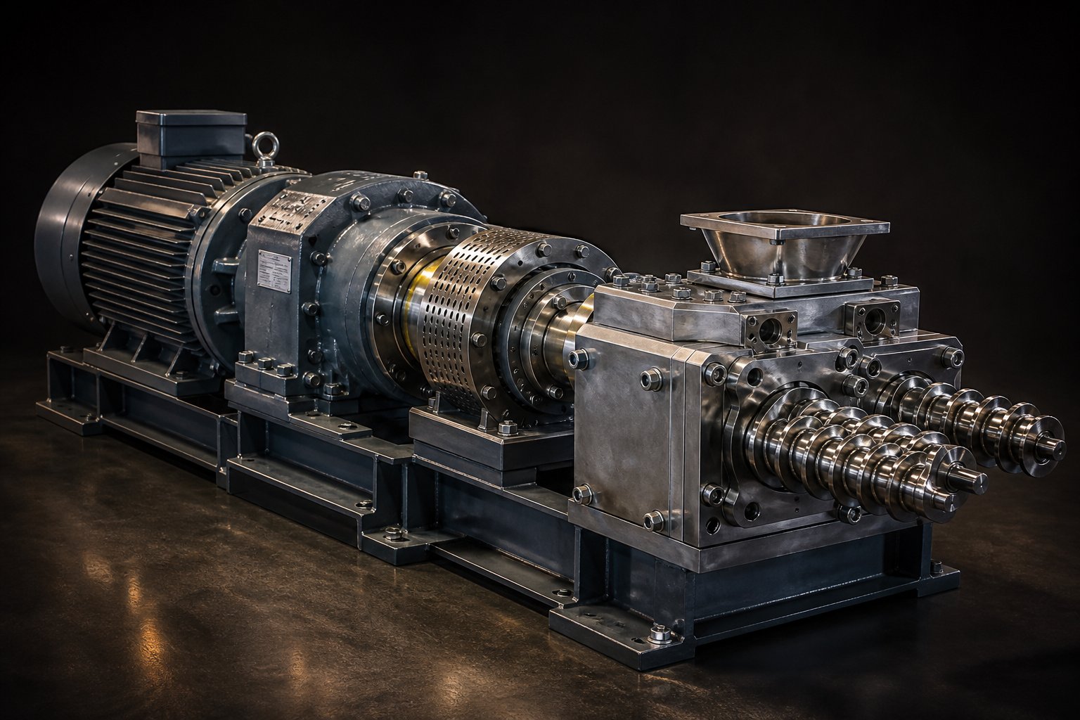
Power Consumption and Torque Requirement Calculations
Throughput tells you how much material the screw moves. Energy and torque tell you what it costs to move it - and whether the motor can handle it at all. These calculations are the most practically consequential numbers in the entire design process, yet they're the ones most consistently missing from published references. Without them, you're guessing at motor sizes, flying blind on process consistency, and losing the single best diagnostic metric available for troubleshooting twin screw extruder power consumption problems.
The organizing concept is simple. Every kilogram of material that passes through the extruder absorbs a measurable amount of energy. That energy comes from two sources: the rotating screws (mechanical) and the heated barrels (thermal). The total is called specific energy (SE):
SE = P / Q
where P is the power consumed (kW) and Q is the mass throughput (kg/hr). SE is expressed in kWh/kg and serves as the most universal benchmarking parameter in twin screw extrusion. A product that consistently runs at an SE of 0.25 kWh/kg and suddenly drops to 0.16 - with no changes to machine hardware or process conditions - implies that the feedstock itself has changed. That kind of instant diagnostic power makes SE one of the first numbers experienced engineers check when something goes wrong.
Specific Mechanical Energy and Specific Thermal Energy Formulas
Specific energy splits into two components, and understanding the distinction matters enormously for screw design decisions. Specific mechanical energy (SME) is the energy transferred from the motor through the rotating screws into the material. Specific thermal energy (STE) is the net energy contribution from barrel heaters minus any cooling applied. The relationship is:
SE = SME + STE
SME is calculated directly from torque, screw speed, and throughput. The formula is:
SME = (2pi x N x tau) / Q
where N is the screw speed in revolutions per second, tau is the applied torque in Newton-meters, and Q is mass throughput in kg/s. In practice, many plants don't have direct torque readouts. Instead, they work from motor power and percent torque displayed on the control panel. A more plant-friendly calculation, widely used in HSEI (high-speed energy input) twin screw operations, uses a two-step approach:
kWapplied = kWmotor rating x %torque x (rpmrunning / rpmmax) x 0.97
The 0.97 factor accounts for gearbox efficiency losses. Then:
SME = kWapplied / (kg/hr)
Imagine a 40 mm twin screw extruder processing mineral-filled PP at 160 kg/hr, running at 400 rpm with 68% torque. The machine has a 56 kW motor and a maximum screw speed of 600 rpm. Plugging in:
kWapplied = 56 x 0.68 x (400 / 600) x 0.97 = 24.6 kW
SME = 24.6 / 160 = 0.154 kWh/kg
STE, by contrast, is harder to measure directly. It's the algebraic sum of heat added by barrel heaters minus heat removed by barrel cooling systems. In many compounding operations, the screws provide most of the process energy through viscous shear, and barrel zones actually run in cooling mode to remove excess heat. In those cases, STE is negative - the barrels are absorbing energy rather than contributing it. For processes where barrel heating dominates (think low-viscosity reactive extrusion or pharmaceutical hot-melt extrusion at low screw speeds), STE can be the larger contributor to total SE.
The HSEI concept, introduced by industry experts at Leistritz, specifically distinguishes co-rotating intermeshing extruders that operate at high screw speeds (up to 1200+ rpm) and rely primarily on SME for energy input. These machines are designed so the motor - not the barrel heaters - does the heavy lifting. Understanding where your process falls on the SME-versus-STE spectrum directly influences screw design: an SME-dominated process benefits from aggressive kneading blocks and high screw speeds, while an STE-dominated process requires longer residence time in heated zones and gentler screw configurations.
A case study by Dow's Carlos Escobar demonstrated this principle during scaleup of a polyolefin masterbatch across 26 mm, 40 mm, and 92 mm co-rotating extruders. The optimized SME on the lab-scale machine was 0.083 kWh/kg. When the 92 mm production extruder initially delivered only 0.026 kWh/kg - a 69% drop - the result was unmolten pellets discharging through the diverter valve. Only after screw redesign and feeding adjustments brought the SME back to 0.086 kWh/kg did the process produce a homogeneous melt. The lesson is clear: SME isn't just a monitoring number. It's a hard process requirement.
The following table provides typical SE ranges by application type to help you benchmark your own process:
| Application Type | Typical SE Range (kWh/kg) | Dominant Energy Source | Engineering Notes |
|---|---|---|---|
| Polymer compounding (general) | 0.10 - 0.30 | SME (screw shear) | Higher end for engineering resins; lower for polyolefin masterbatch |
| Reactive extrusion | 0.05 - 0.20 | SME + STE (variable) | Reaction kinetics may require longer residence time over raw energy input |
| Devolatilization | 0.08 - 0.15 | SME + STE | Low fill levels increase surface renewal; SE target depends on solvent load |
| Powder coatings | 0.04 - 0.08 | SME | Low-viscosity melts require minimal energy; torque rarely a constraint |
| Pharmaceutical HME | 0.05 - 0.25 | STE + SME | API sensitivity drives upper limits; barrel heating often significant contributor |
| Food processing | 0.05 - 0.20 | SME | Starch gelatinization and protein texturization are shear-energy-dependent |
Torque Requirements and Motor Sizing
Torque is the rotational force the motor applies through the gearbox and screw shafts to process material. It's the parameter that physically limits what the extruder can do at any given screw speed. The fundamental twin screw extruder torque calculation relates torque directly to motor power and rotational speed:
tau = (P x 60) / (2pi x N) = (9550 x kW) / rpm
where tau is the total torque for both shafts in Newton-meters, P is the motor power in kW, and N is the screw speed in rpm. The constant 9550 is simply (60 x 1000) / (2pi), converting between kW, N-m, and rpm in a single step.
Here's a practical example from industry HSEI guidelines. A 60 mm extruder with a torque rating of 2800 N-m can pair with a 200 kW motor geared for 600 rpm or a 400 kW motor geared for 1200 rpm:
2800 = (9550 x 200) / 600
2800 = (9550 x 400) / 1200
The torque is identical. If your process runs entirely between 0 and 600 rpm, there's no mechanical advantage to specifying the 400 kW drive - only additional cost. The larger motor only pays for itself if the process benefits from higher screw speeds, where the additional power is consumed at the same torque but faster rotation.
Maximum allowable torque is constrained by three factors: the cross-sectional area of the screw shafts, the shaft metallurgy and manufacturing method, and the gearbox rating. This is where the Do/Di ratio becomes critical again. A lower Do/Di means a larger root diameter and therefore a larger shaft cross-section, enabling higher torque transmission. OEM manufacturers often express this limit as specific torque - torque per unit of centerline distance cubed (N-m / a3, where a is the center distance between screw axes). Specific torque provides a machine-size-independent metric that allows direct comparison of the torque capacity of different extruder platforms.
When the control panel shows torque approaching 100%, failsafe logic kicks in to reduce screw speed or feeder rate, preventing shaft breakage or gearbox damage. Running consistently above 85-90% torque leaves inadequate margin for process upsets like feed surges or viscosity spikes. If your twin screw extruder torque calculation shows the process routinely operating near the shaft limit, the fix is either a larger machine, a different Do/Di ratio with greater torque capacity, or a reformulated screw design that requires less energy per kilogram.
Power Consumption Estimation During Screw Design
During the design phase - before the machine ever runs - you need to estimate the required motor power. The calculation works backward from process targets:
Prequired = SEtarget x Qtarget x safety factor
If your target throughput is 500 kg/hr and the expected SE for your application is 0.20 kWh/kg, the baseline power requirement is 100 kW. A safety factor of 1.2 to 1.3 accounts for process variability, startup conditions, and feed fluctuations, yielding a motor specification of 120 to 130 kW.
The relationship between power, screw speed, and fill level adds a practical wrinkle. In starve-fed operation, increasing screw speed at constant feed rate decreases the fill level. Less material in the channels means less resistance to screw rotation and therefore less torque draw. Power consumption (which equals torque times speed) may actually plateau or even decrease at very high speeds if the reduced fill effect outweighs the increased rotational speed. Conversely, increasing feed rate at constant screw speed raises fill level, increases the shear stress on the material, and drives torque and power consumption upward.
This interplay explains why scaleup from laboratory to production extruders isn't simply a matter of matching screw speed. The area-to-volume ratio of the barrel decreases dramatically with increasing diameter, which changes the relative contributions of SME and STE. A process that runs comfortably on a 26 mm machine at a given SME may require a completely different screw design on a 92 mm machine to deliver the same energy input per kilogram - a reality that Dow's scaleup case study confirmed across three extruder sizes.
Energy and torque tell you how hard the screw is working. But they don't tell you how it's working - whether the material is being gently conveyed or aggressively sheared, whether channels are full or nearly empty. Those answers require two more calculations that most references skip entirely: shear rate and fill factor.
Shear Rate and Fill Factor Calculations for Process Optimization
A twin screw extruder plastic compounding line can deliver perfect throughput numbers and run well within its torque envelope - and still produce unusable product. The pellets come out with black specks from thermal degradation, or the filler dispersion is inconsistent, or the devolatilization vent floods and shuts down the line. None of those problems show up in the throughput or energy calculations covered so far. They live in two parameters that most engineering references skip entirely: shear rate and fill factor.
Shear rate tells you how aggressively the screw deforms the material at any given point. Fill factor tells you how much of the available channel volume actually contains material. Together, they determine whether a twin screw plastic extruder gently conveys material through a partially empty channel or violently shears it through a fully packed kneading zone. Getting both right is essential for predicting mixing quality, thermal degradation risk, and devolatilization performance.
Apparent Shear Rate Calculations in Screw Channels
The apparent shear rate in a screw channel describes how fast adjacent layers of material slide past each other. Picture the material sandwiched between the rotating screw root and the stationary barrel wall: the barrel surface velocity is zero, the screw surface moves at the tip speed, and the channel depth is the distance between them. The resulting twin screw extruder shear rate in the channel is:
γ̇channel = (π × D × N) / H
where D is the outer screw diameter, N is the screw speed in revolutions per second, and H is the channel depth. This formula produces the nominal shear rate in the main flow channel of a conveying element - think of it as the baseline shear the material experiences during forward transport.
But the channel isn't the only place material gets sheared. The overflight gap - the narrow clearance between the screw flight tip and the barrel wall - subjects material to far more intense deformation. Leistritz's published formula for peak shear rate in this gap is:
γ̇peak = (π × D × n) / (h × 60)
where D is the screw outer diameter in mm, n is the screw speed in rpm, h is the overflight gap in mm, and the factor of 60 converts rpm to revolutions per second. Consider a practical example: a TSE with a 77.5 mm outer diameter screw, a 0.55 mm overflight kneading gap, running at 600 rpm produces a peak shear rate of approximately 4,867 s-1. That's an order of magnitude higher than the channel shear rate for the same screw at the same speed - because the gap is an order of magnitude thinner than the channel depth.
Why does this matter? Because material passing through the overflight gap experiences an extensional mixing effect followed by intense planar shear. This concentrated deformation is what drives dispersive mixing - breaking apart agglomerates, rupturing droplets, and separating filler clusters. Industry experts note that while the peak shear rate calculation oversimplifies the full mixing picture (it ignores extensional flow contributions), it serves as a highly effective benchmarking tool for troubleshooting mixing quality.
Shear rate varies dramatically across different screw element types. Conveying elements with deep channels produce relatively low shear rates - their job is transport, not mixing. Kneading blocks operate differently: the stagger angle between successive kneading discs determines how much material is forced through the overflight region versus allowed to pass through the open channel. A 30-degree forward stagger provides moderate mixing with continued forward conveying. A 60-degree stagger intensifies the mixing action. A 90-degree (neutral) stagger maximizes shear intensity but provides zero forward conveying, and reverse-stagger kneading elements actively oppose forward flow, creating a fully filled, high-pressure zone upstream.
The following table illustrates how channel shear rate changes with varying channel depth and screw speed for a representative 50 mm diameter screw:
| Channel Depth H (mm) | Shear Rate at 200 rpm (s-1) | Shear Rate at 400 rpm (s-1) | Shear Rate at 600 rpm (s-1) | Shear Rate at 800 rpm (s-1) |
|---|---|---|---|---|
| 3.0 (shallow) | 1,745 | 3,491 | 5,236 | 6,981 |
| 5.0 (moderate) | 1,047 | 2,094 | 3,142 | 4,189 |
| 8.0 (deep) | 654 | 1,309 | 1,963 | 2,618 |
| 12.0 (very deep) | 436 | 873 | 1,309 | 1,745 |
You'll notice a clear pattern: doubling the channel depth cuts the shear rate in half, while doubling the screw speed doubles it. The relationship is perfectly linear - a direct consequence of the formula's structure. For overflight gaps (typically 0.3 to 0.8 mm), the same formula produces shear rates in the thousands to tens of thousands per second. That's why kneading blocks with tight overflight clearances are the primary dispersive mixing tools in any twin screw extruder configuration, and why worn kneading elements with enlarged gaps lose their mixing effectiveness long before they affect throughput.
The connection to material quality is direct. Multiply the shear rate by the local melt viscosity, and you get shear stress - the force that actually breaks apart agglomerates and disperses fillers:
Shear stress = γ̇ × η
Leistritz technical data confirms that viscosities are higher in the early extruder stages, producing high stress rates that drive dispersive mixing - or, for shear-sensitive materials, cause degradation. In the latter stages, viscosities drop as the melt heats up, and the resulting lower stress rates reduce dispersive capability. Engineers sometimes counterintuitively apply barrel cooling in the late mixing zone specifically to increase local viscosity and recover the shear stress needed for a final dispersion pass.
Fill Factor and Degree of Fill Estimation
Shear rate describes the intensity of deformation. Fill factor describes how much material is present to experience it. The fill factor (f) is the ratio of actual material volume in the channel to the total available channel volume:
f = Q / (Qd × ρ)
where Q is the actual mass throughput, Qd is the theoretical drag flow capacity (from the throughput equations in the previous section), and ρ is the material density. A fill factor of 1.0 means the channel is completely full. A fill factor of 0.3 means only 30% of the available volume contains material.
Here's a concept that surprises engineers coming from single screw backgrounds: most of a co-rotating twin screw extruder runs partially filled. In starve-fed operation - the standard mode for nearly all co-rotating compounders - the gravimetric feeder meters material at a rate well below the screw's maximum drag flow capacity. The result is that conveying zones typically operate at fill factors between 0.15 and 0.40. Only where the screw geometry creates a restriction - a kneading block, a reverse element, a die - does material accumulate and the fill factor approach 1.0.
The practical index engineers use to evaluate fill state is the Q/N ratio (throughput divided by screw speed). As Technovel's experimental research demonstrated through split-barrel visualization studies, Q/N is proportional to the fill ratio in partially filled conveying sections:
Q/N = η × C
where η is the local fill ratio and C is a volumetric coefficient determined by barrel and screw geometry. Their experiments on a 15 mm twin screw extruder showed that conditions with the same Q/N produced nearly identical fill states - even when the absolute throughput and screw speed differed by a factor of ten. Higher Q/N values consistently produced higher average fill ratios inside the machine. Critically, though, while the same Q/N creates equivalent fill states, the residence time and shear history differ substantially because the screw speeds are different.
Fill factor is not uniform along the screw length. It varies zone by zone, dictated by the local screw element type:
- Feed zone: Partially filled. Bulk solids are metered in below the screw's conveying capacity.
- Conveying zones: Partially filled. Material moves forward with minimal pressure gradient.
- Upstream of kneading blocks: Fill increases as the restrictive element creates backpressure.
- Kneading zones: Fully or nearly fully filled. This is where mixing intensity peaks.
- Vent zones: Deliberately low fill to maximize free surface for volatile removal.
- Pressure buildup zone (pre-die): Fully filled. The screw must generate die pressure here.
Why Shear Rate and Fill Factor Drive Processing Quality
These two parameters interact to determine nearly every quality outcome in twin screw extrusion. Understanding the interaction - not just the individual values - is what separates effective troubleshooting from guesswork.
Excessive shear rate causes thermal degradation. When channel shear rates or overflight peak shear rates exceed the material's tolerance, viscous dissipation generates heat faster than the barrel cooling system can remove it. The result is localized overheating that degrades polymer chains, discolors the product, or destroys shear-sensitive additives. This is especially critical for bioplastics like PLA and PHA, where Leistritz processing studies have shown that modifying the melting zone screw design to reduce shear intensity directly lowered both torque draw and melt temperature. For glass fiber and carbon fiber reinforced compounds, excessive shear also reduces fiber length, degrading the mechanical properties of the final product.
Insufficient fill in kneading zones reduces mixing quality. A kneading block that's only 40% filled doesn't generate the screw-to-screw material transfer and compressive deformation that drives distributive mixing. The material simply tumbles through the open channel without experiencing the full shearing effect. CFD simulations by Ahmed and Chandy studying fill factor effects on rubber mixing found that fill factors between 70% and 80% produced the most effective combination of dispersive and distributive mixing characteristics. Below that range, mixing quality deteriorated; above it, viscous heating and machine load became problematic.
Incorrect fill factor estimation leads to vent flooding. Devolatilization zones require low fill factors - typically below 0.20 to 0.30 - to create the free surface area needed for volatiles to escape. If the upstream screw configuration doesn't consume enough pressure to keep the vent zone starved, material backs up into the vent port. The result is a "vent flood" that forces a shutdown. Calculating the expected fill factor at each vent location - using Q/N, local drag flow capacity, and the restrictive effect of upstream elements - is the primary engineering defense against this failure mode.
The twin screw extrusion process is not a simple choice between high fill and low fill. The right approach is to design the optimal fill state zone by zone, matching each section's fill ratio to its intended function.
An engineer who can calculate shear rate and fill factor for each zone along the screw has the conceptual framework to predict - before cutting metal - whether a proposed screw configuration will mix effectively without degrading the material, vent properly without flooding, and build pressure without exceeding the torque limit. These are fundamentally local calculations: one screw design contains zones with shear rates varying by an order of magnitude and fill factors ranging from 0.15 to 1.0. The overall machine performance emerges from the combined behavior of every zone in sequence.
That zone-by-zone variation raises a deeper question: do all these formulas apply the same way to every type of twin screw extruder? The answer depends entirely on whether the screws rotate in the same direction or opposite directions - a distinction that changes the flow physics, the geometry constraints, and even the form of the throughput equations themselves.
Co-Rotating vs Counter-Rotating Design Calculation Differences
Every formula presented so far - drag flow, shear rate, fill factor, specific energy - carries an implicit assumption about how the two screws interact. Change the direction of rotation, and you change the flow physics at the intermeshing zone. Change the barrel geometry from parallel to conical, and you introduce variable diameters that make every calculation position-dependent. Yet most engineering references treat "twin screw extruder" as a single category, presenting one set of equations and hoping readers figure out the rest. That approach breaks down the moment you try to apply a co-rotating throughput equation to a counter-rotating machine, or vice versa.
The differences aren't cosmetic. A co-rotating twin screw extruder and a counter-rotating twin screw extruder use fundamentally different conveying mechanisms, which changes the mathematical form of the throughput equation, the meaning of fill factor, and the way shear stress develops in the intermeshing region. Understanding which formulas apply to your twin screw extruder configuration - and where they need modification - prevents engineering errors that no amount of simulation post-processing can fix.
Co-Rotating Intermeshing Geometry and Flow Differences
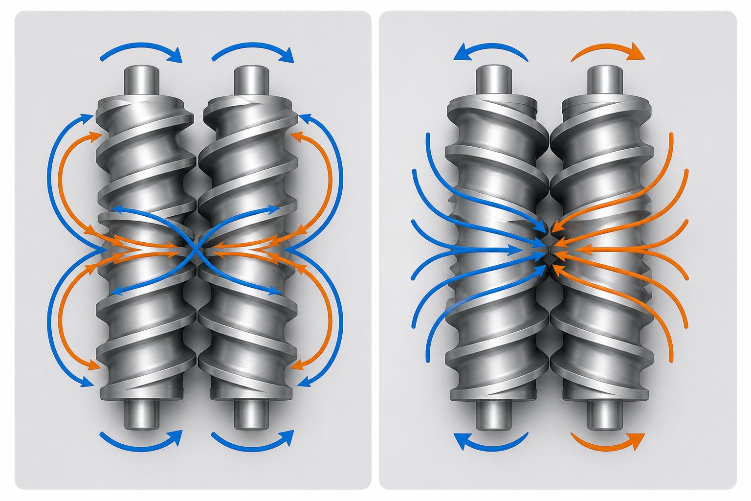
In a co-rotating twin screw extruder, both screws turn in the same direction inside a figure-eight barrel cross-section. The defining geometric constraint is self-wiping: the flight of one screw sweeps the root of the other, maintaining tight clearances that prevent material stagnation. This self-wiping requirement directly constrains the Do/Di relationship - you can't independently choose the outer diameter and root diameter because the intermeshing geometry dictates how they relate. For a standard bi-lobal (two-start) profile, the centerline distance between screws equals the inner diameter, and the channel depth on one screw must match the flight geometry of the other.
The flow pattern is distinctive. Material doesn't simply travel down a single helical channel the way it does in a single screw system. Instead, it follows a figure-eight path, transferring from one screw to the other at the intermeshing zone with each revolution. Technovel's technical analysis describes this as material being "forcibly handed off to the next flight at the intermeshing region," with very few dead zones inside the barrel. This periodic transfer between screws creates a narrow residence time distribution - material that enters first tends to exit first, with minimal bypassing or back-mixing in conveying zones.
For the throughput equations, this figure-eight transfer means the drag flow calculation must account for contributions from both screw channels working in tandem. The standard drag flow equation presented earlier (Qd = 1/2 × π × D × N × H × W × sin(φ) × cos(φ)) applies per channel, but the total throughput of the co-rotating system reflects the combined action of both screws minus the intermesh overlap region. In practice, most engineers apply the single-channel equation and multiply by a geometric correction factor that accounts for the figure-eight barrel cross-section.
The shear field in a co-rotating system is intense by design. Because both screws rotate in the same direction, material at the intermeshing zone experiences high relative velocity between the approaching flight surfaces. Shear stress between the screws is high and mixing proceeds with considerable intensity - a characteristic that makes co-rotating machines the default choice for dispersive compounding, polymer alloying, and reactive extrusion where aggressive mixing is the goal. The overflight shear rate formula (γ̇ = π × D × N / h) remains valid, but engineers must recognize that additional shear contributions arise from the screw-to-screw interaction at the intermeshing apex, which the simple overflight calculation doesn't capture.
Counter-Rotating and Conical Twin Screw Calculation Adjustments
Flip one screw's rotation direction, and the physics change dramatically. In a counter-rotating twin screw extruder, the screws turn in opposite directions. At the intermeshing zone, material is drawn inward between the screws and compressed forward - rather than being transferred laterally in a figure-eight pattern. The result is a series of closed C-shaped chambers formed between consecutive flights and the barrel wall. Material trapped in each chamber advances axially as the screws rotate, creating a positive displacement conveying mechanism that's closer to a gear pump than a drag-flow conveyor.
This fundamentally changes the throughput equation. Instead of the drag-flow and pressure-flow formulation used for co-rotating systems, counter-rotating throughput is better described volumetrically:
Q = 2 × nchambers × Vchamber × N × f
where nchambers is the number of C-shaped chambers per screw revolution, Vchamber is the volume of each closed chamber, N is the screw speed, and f is the volumetric fill factor. The factor of 2 accounts for both screws. Because throughput depends primarily on chamber volume and rotational speed rather than on the velocity gradient across the channel, these machines are far less sensitive to downstream pressure fluctuations. A die restriction that would cause significant pressure back flow in a co-rotating system has a proportionally smaller effect on counter-rotating throughput.
The mixing mechanism differs as well. Counter-rotating intermeshing screws generate a calendering effect at the intermeshing region - material passes between the approaching screw surfaces much like sheet material passes between calender rolls. Technovel notes that this calendering effect subjects material to compressive and elongational deformation under relatively gentle conditions, making counter-rotating machines particularly effective for thermally sensitive materials like rigid PVC. The shear rate at the intermeshing zone is lower than in a co-rotating system at the same screw speed because the relative surface velocities partially cancel rather than reinforce each other.
A conical twin screw extruder introduces yet another calculation layer. In a conical design - almost always counter-rotating - the screw diameter decreases continuously from the feed end to the discharge end. This means every geometry-dependent formula becomes position-dependent along the screw length:
- Channel depth H(z) varies as both Do and Di change with axial position z
- Screw surface velocity decreases toward the discharge end because circumference shrinks while rpm stays constant
- Shear rate γ̇(z) changes along the length even with constant channel depth proportions, since D(z) is decreasing
- Chamber volume Vchamber(z) decreases progressively, creating a built-in compression without requiring changes to channel depth ratios
For engineers calculating throughput in a conical system, the volumetric equation still applies, but Vchamber must be evaluated at the discharge end where the smallest chambers control the output rate. The large-diameter feed section provides excellent material intake - especially for low-bulk-density powders - while the small-diameter discharge section generates high pressure for die forming. This natural compression eliminates the need for the complex screw element sequencing that parallel machines require to achieve equivalent pressure profiles.
Compression Ratio Calculations Across Configurations
The extrusion screw compression ratio quantifies how much the available volume decreases from the feed section to the metering (discharge) section. It directly determines how aggressively the screw densifies and pressurizes material. For a parallel twin screw extruder, the compression ratio is defined as:
CR = Hfeed / Hmetering
where Hfeed is the channel depth in the feed zone and Hmetering is the channel depth in the metering zone. Since parallel screws maintain constant outer and inner diameters along their length, compression is achieved entirely by changing the channel depth through screw element selection - transitioning from deep-channel conveying elements to shallow-channel metering elements.
For a conical twin screw extruder, the compression ratio calculation is more nuanced. Because the diameter changes continuously, compression results from the combined effect of decreasing diameter and any additional change in channel depth proportions. A more representative expression uses the volume ratio:
CRconical = Vchannel, feed / Vchannel, discharge
This captures both the diameter reduction and any change in relative channel depth. A conical design with a 2:1 diameter taper inherently provides substantial compression even if the channel depth ratio (H/D) remains constant along the length - a geometric advantage that simplifies screw design for applications like PVC pipe extrusion where consistent, progressive compression is critical.
The following table consolidates the key design calculation differences across all three major twin screw extruder configurations:
| Parameter | Co-Rotating Parallel | Counter-Rotating Parallel | Counter-Rotating Conical |
|---|---|---|---|
| Typical Do/Di Range | 1.40 - 1.66 | 1.20 - 1.55 | Variable (tapers along length) |
| Conveying Mechanism | Drag flow with figure-eight transfer | Positive displacement (C-chambers) | Positive displacement with decreasing chamber volume |
| Throughput Equation Form | Q = Qd - Qp - Ql | Q = 2 × n × Vchamber × N × f | Q = 2 × n × Vchamber(discharge) × N × f |
| Typical L/D Range | 32:1 - 48:1 | 22:1 - 34:1 | 16:1 - 26:1 (equivalent) |
| Shear Intensity at Intermesh | High (reinforcing velocities) | Low to moderate (calendering effect) | Low to moderate; decreases toward discharge |
| Compression Ratio Method | Screw element selection (Hfeed/Hmetering) | Screw element selection | Built-in via diameter taper + element selection |
| Primary Applications | Compounding, reactive extrusion, devolatilization, pharma HME | PVC profiles, pipes, sheets; shear-sensitive materials | PVC pipe and profile extrusion; window frames |
Notice how the throughput equation itself changes form between co-rotating and counter-rotating machines. Applying the drag-flow/pressure-flow model to a tightly intermeshing counter-rotating system would underestimate its pressure-generating capability and mischaracterize its conveying behavior. Similarly, using the volumetric positive-displacement model for a co-rotating system would ignore the significant pressure back flow that occurs in fully filled zones. Choosing the wrong equation form isn't a rounding error - it's a conceptual error that produces misleading results.
The counter-rotating configuration's low-shear calendering effect also means that shear rate calculations using the standard channel formula (γ̇ = π × D × N / H) overestimate the actual deformation in the intermeshing region. For co-rotating machines, the formula underestimates it because it doesn't capture the additional screw-to-screw shear contribution. Engineers must apply these formulas with awareness of which configuration they're designing for - and adjust their expectations accordingly.
With the mathematical framework now complete across all major configurations, the remaining challenge is practical: translating these equations into parameter recommendations that actually work for specific applications, and using the calculations as diagnostic tools when a process falls short of its targets.
Twin Screw Extruder Parameters: Recommendation Tables and Troubleshooting with Calculations
Formulas without starting points are just academic exercises. You can know exactly how to calculate drag flow, shear rate, and specific energy - but if you don't know where to begin for a given application, you'll spend weeks iterating through trial geometries before landing on a workable design. That's the gap between theoretical knowledge and engineering productivity. The twin screw extruders market spans plastics compounding, reactive processing, pharmaceutical extrusion, and food manufacturing, and each application occupies a distinct zone in the parameter space. Experienced engineers carry these starting ranges in their heads. Everyone else deserves a table.
Recommended Parameter Ranges by Application Type
The table below consolidates twin screw extruder parameters into a single reference organized by application. These ranges represent established engineering starting points drawn from published processing data and OEM guidelines - not guaranteed optima. Every material system and machine platform introduces its own constraints, but these values give you a defensible first pass for screw design calculations before refining through experimentation.
| Application | Typical L/D Ratio | Recommended Do/Di | Screw Speed Range (rpm) | SE Target (kWh/kg) | Typical Compression Ratio | Target Shear Rate Range (s-1) |
|---|---|---|---|---|---|---|
| Plastics Compounding (general) | 36:1 - 48:1 | 1.55 - 1.66 | 300 - 900 | 0.10 - 0.30 | 1.3 - 2.0 | 500 - 5,000 |
| Reactive Extrusion | 36:1 - 52:1 | 1.40 - 1.55 | 100 - 600 | 0.05 - 0.20 | 1.2 - 1.8 | 200 - 3,000 |
| Devolatilization | 40:1 - 52:1 | 1.55 - 1.71 | 200 - 600 | 0.08 - 0.15 | 1.2 - 1.5 | 300 - 2,500 |
| Pharmaceutical HME | 24:1 - 40:1 | 1.40 - 1.66 | 50 - 400 | 0.05 - 0.25 | 1.1 - 1.5 | 100 - 2,000 |
| Food Processing | 20:1 - 36:1 | 1.55 - 1.71 | 100 - 500 | 0.05 - 0.20 | 1.5 - 3.0 | 100 - 1,500 |
A few patterns stand out immediately. Plastics compounding and devolatilization favor higher L/D ratios because they need multiple functional zones - melting, mixing, venting, and pressure buildup - strung along a longer processing length. Pharmaceutical hot-melt extrusion typically works with shorter L/D because the API (active pharmaceutical ingredient) is thermally sensitive, and shorter residence time reduces degradation risk. Food processing tends toward high Do/Di ratios for maximum free volume, accommodating the low bulk density of starch and protein feedstocks.
Notice the shear rate ranges. Plastics compounding may push toward 5,000 s-1 in kneading zones to achieve dispersive mixing of pigments or nanofillers, while food and pharmaceutical applications cap shear rates well below that threshold to protect sensitive ingredients. Reactive extrusion sits in a middle ground where sufficient mixing is needed to initiate and sustain chemical reactions, but excessive shear generates unwanted heat that can shift reaction selectivity or degrade products.
These starting parameters feed directly into the design equations covered in earlier sections. Picking a Do/Di of 1.55 sets your channel depth. That channel depth, combined with your target screw speed, determines your shear rate via the channel shear formula. The shear rate and fill factor together influence the SME, which you can check against the SE target in the table. If any calculated value falls outside the recommended range, you've identified a design mismatch before building anything.
Using Calculations to Diagnose Processing Problems
Design calculations aren't just for new screw specifications. They're equally powerful as twin screw extruder troubleshooting tools for processes that are already running - and running badly. The same formulas that predict performance during design can diagnose failures during production, provided you know which calculation maps to which symptom.
Consider two diagnostic scenarios that illustrate the principle. First: if the actual specific energy significantly exceeds the calculated SME, it means barrel heating - not screw work - dominates the energy input. The screw configuration is underworking the material. In practice, this shows up when barrel zone temperatures are all in heating mode rather than cooling, yet the product still lacks adequate mixing or melting. The fix lives in the screw design: more aggressive kneading blocks, tighter overflight gaps, or higher screw speeds to shift the energy balance back toward mechanical input.
Second: if torque is at maximum but throughput remains below target, the machine's torque density has become the bottleneck. The twin screw extruder torque calculation reveals whether the Do/Di ratio provides sufficient shaft cross-section for the required mechanical energy. A machine with a high Do/Di (deep channels, low torque density) may simply lack the shaft strength to process a high-viscosity resin at the desired rate. Reducing throughput or switching to a machine platform with a lower Do/Di and higher torque capacity becomes the engineering solution.
Industry troubleshooting experts reinforce this calculation-based diagnostic approach. Adam Dreiblatt of CPM Century Extrusion categorizes compounding problems as either "chronic" or "transient" - chronic problems indicate fundamental design mismatches requiring screw reconfiguration, while transient issues point to temporary conditions like raw material lot changes or mechanical failures. The design calculations tell you which category you're dealing with: if your calculated parameters show the screw is geometrically incapable of achieving the required shear rate or specific energy, the problem is chronic, and no amount of process adjustment will fix it.
The following list maps common processing problems to the specific design calculations that help pinpoint each root cause:
- Poor dispersive mixing - Calculate overflight shear rate (gamma = pi x D x N / h). If peak shear rate falls below the threshold needed to rupture agglomerates, kneading block gap or stagger angle requires modification.
- Output surging - Evaluate fill factor in conveying zones and check feeder speed variation. If fill factor oscillates, the cause is typically feeder pulsation or inconsistent bulk density at the feed throat. Acceptable feeder variation is plus or minus 1-2%.
- Excessive melt temperature - Compare calculated channel shear rate to material limits. Excessive viscous dissipation in deep kneading zones or worn flight clearances drives localized overheating beyond what barrel cooling can compensate.
- Vent flooding - Estimate fill factor at each vent location using Q/N and local drag flow capacity. If the fill factor exceeds 0.20-0.30 at the vent, upstream restrictive elements aren't creating sufficient melt seal, or throughput exceeds vent zone capacity.
- Low throughput at target quality - Verify drag flow capacity at operating screw speed. If Qd barely exceeds the target Q, there's no headroom for pressure flow and leakage losses. A higher pitch, faster screw speed, or larger Do/Di ratio increases conveying capacity.
- Torque-limited operation - Recalculate required SME at the target throughput and compare to the machine's maximum torque at operating speed. If SME demands exceed shaft capacity, the process needs either a different Do/Di ratio, a lower-viscosity feed condition, or screw elements that reduce energy input per revolution.
Each diagnostic path leads to a specific calculation, and each calculation points to a specific parameter change. That's the real value of mastering these formulas: they transform vague symptoms like "the product doesn't look right" into precise engineering actions like "increase kneading block stagger angle from 30 to 60 degrees to raise peak shear rate from 2,400 to 4,100 s-1."
When calculation results point toward custom screw geometry optimization - whether that means adjusting Do/Di ratios for a different torque-volume balance, redesigning kneading block sequences to hit target shear rates, or selecting wear-resistant materials for high-torque applications - the gap between theoretical calculation and production-ready hardware becomes the critical challenge. Services like NANHAIYA's Custom Screw Design provide tailored engineering recommendations that account for specific polymers, machine conditions, and output requirements, bridging that gap between the numbers on your spreadsheet and a screw configuration that actually performs on the production floor.
Calculations identify the problem. Parameter tables provide the target. But translating both into a buildable, validated screw configuration requires a structured workflow that takes an engineer from initial process requirements through final design verification - step by step, with nothing left to chance.
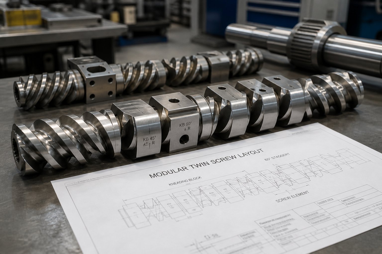
From Design Calculations to Production-Ready Screw Configurations
You've now seen every core formula - geometry, throughput, energy, shear rate, fill factor - and you understand how they differ across co-rotating and counter-rotating configurations. But formulas scattered across eight sections don't automatically become an engineering method. What's missing is the sequence: which calculation comes first, which depends on which, and where you circle back when the numbers don't converge. A structured twin screw extruder design workflow turns isolated equations into a repeatable process that moves from a blank specification sheet to a verified screw design - with clear decision points at every stage.
Step-by-Step Calculation Workflow for Twin Screw Extruder Design
The following sequence represents the complete calculation methodology. Each step builds on the outputs of the previous one, and step nine sends you back through the loop when adjustments are needed. Treat it as a checklist - skip a step, and the downstream calculations lose their foundation.
- Define process requirements. Establish target throughput (kg/hr), identify the polymer or material system, and list every unit operation the screw must perform: melting, distributive mixing, dispersive mixing, devolatilization, reactive processing, or pressure buildup. These requirements set the boundary conditions for every calculation that follows.
- Select machine configuration. Choose co-rotating versus counter-rotating based on the mixing intensity and shear sensitivity of the application. Select the Do/Di ratio to balance free volume against torque density. Set the L/D ratio to accommodate the number of functional zones identified in step one. Use the parameter recommendation tables as starting points.
- Calculate screw geometry. Derive channel depth (H) from Do and Di. Determine pitch (P) for each zone based on the required conveying rate and pressure profile. Calculate helix angle, flight width, and flight clearance. Verify that the compression ratio - Hfeed / Hmetering for parallel designs, or volume ratio for conical designs - falls within the target range for the application.
- Verify throughput using flow equations. Calculate drag flow (Qd) at the target screw speed. Estimate pressure back flow (Qp) based on expected die resistance and any fully filled restrictive zones. Account for leakage flows (Ql) through overflight, calendering, and intermesh gaps. Confirm that net throughput Q = Qd - Qp - Ql meets or exceeds the target with adequate margin.
- Calculate power and torque requirements. Multiply target throughput by the expected specific energy for the application to estimate required motor power. Add a 1.2x to 1.3x safety factor. Verify that the resulting torque at operating screw speed falls within the shaft's mechanical limit using tau = (9550 x kW) / rpm. If torque exceeds capacity, revisit Do/Di selection or reduce the target screw speed.
- Check shear rate profiles against material limits. Calculate the apparent channel shear rate (gamma = pi x D x N / H) for every element type in the configuration. Calculate peak overflight shear rate in kneading zones using the overflight gap dimension. Compare both values to the material's known degradation threshold. If any zone exceeds the limit, reduce screw speed, increase local channel depth, or replace aggressive kneading elements with gentler distributive mixing elements.
- Estimate fill factor in each zone. Use Q/N and local drag flow capacity to predict fill factor along the screw length. Confirm that kneading zones reach sufficient fill (typically 0.70 to 0.90) for effective mixing. Verify that vent zones remain below 0.20 to 0.30 fill to prevent flooding. Adjust upstream restrictive elements or screw pitch as needed to control zone-by-zone fill state.
- Validate specific energy against application targets. Calculate the expected SME from torque, screw speed, and throughput. Estimate the STE contribution from barrel heating or cooling. Compare total SE to the target range for the application type. If SE falls short, the screw is underworking the material - consider more intensive mixing elements. If SE is excessive, the configuration is over-processing, risking degradation and wasted energy.
- Iterate and optimize. Rarely does the first pass through steps one through eight produce a fully satisfactory design. Adjust one parameter at a time - pitch, kneading block stagger angle, channel depth, screw speed - and re-run the affected downstream calculations. Track how each change ripples through throughput, torque, shear rate, and fill factor. Convergence happens when every calculated value falls within its acceptable range simultaneously.
That ninth step deserves emphasis. Twin screw extruder optimization is inherently iterative. Increasing screw speed to boost throughput raises shear rate, which may push melt temperature past the material's limit. Deepening channels to reduce shear rate increases pressure back flow sensitivity, which may reduce net throughput below target. Extending L/D to add mixing zones increases residence time, which may cause thermal degradation in heat-sensitive systems. Every adjustment creates a cascade. The calculation workflow gives you the tools to trace each cascade quantitatively rather than reacting to symptoms after the fact.
Turning Calculations into Optimized Screw Configurations
Hand calculations establish the engineering foundation. They tell you what channel depth to target, what screw speed range is feasible, how much torque the process demands, and where shear rate or fill factor will become problematic. What they don't tell you - and what no formula alone can determine - is how to sequence individual screw elements along the shaft to achieve all of those targets simultaneously.
Translating calculated parameters into a complete, buildable twin screw extruder screw configuration requires expertise that goes beyond the equations. Element sequencing - deciding exactly where to place forward conveying elements, kneading blocks of specific stagger angles, neutral elements, reverse elements, and specialized mixing geometries - is as much engineering art as science. As CPM Extrusion Group's technical resources emphasize, the same extruder hardware can behave in completely different ways depending on screw design, and matching element selection to material properties is central to successful processing. Technovel's screw design engineers reinforce the same point: on a real extrusion floor, a clean answer like "this condition will always work" hardly exists, and the optimum changes with the required quality, production volume, and thermal history.
Material selection for screw metallurgy adds another dimension. A screw configuration that runs beautifully in standard tool steel may fail within months when processing glass-fiber-filled compounds or titanium dioxide masterbatch that cause abrasive wear. High-torque applications demand shaft materials and heat treatments that maintain torsional strength under sustained mechanical load. These decisions require metallurgical knowledge that complements - but is distinct from - the thermomechanical calculations covered in this article.
Validation against real processing data closes the loop. Calculated shear rates and fill factors are predictions based on idealized assumptions - Newtonian flow, isothermal conditions, perfect barrel-screw geometry. Real polymer melts are shear-thinning, temperature-dependent, and processed in equipment that wears over time. Running the initial screw configuration, measuring actual torque, melt temperature, specific energy, and product quality, and then feeding those measurements back into the calculation framework is what transforms a theoretical design into a proven production tool.
The most effective engineering teams combine rigorous design calculations with experienced screw design support - using the math to define the target and the expertise to hit it.
For engineers and production teams ready to move from calculated parameters to production-ready screw designs, NANHAIYA's Custom Screw Design service offers geometry specification, material selection, and processing recommendations tailored to specific machine platforms and polymer systems. Whether the calculations point toward a revised Do/Di ratio, a new kneading block sequence, or a wear-resistant element upgrade, their engineering team translates the numbers from your spreadsheet into a screw configuration built for your process - making it a practical next step after completing the design calculations outlined in this article.
Frequently Asked Questions About Twin Screw Extruder Design Calculations
1. What is the most important formula for twin screw extruder throughput calculation?
The net throughput formula Q = Qd - Qp - Ql captures the three competing flow components: drag flow (forward pumping by screw rotation), pressure flow (back flow caused by downstream resistance), and leakage flow (material escaping through overflight, calendering, tetrahedron, and side gaps). For starve-fed co-rotating compounders, these equations matter most in fully filled zones like kneading blocks and the pre-die pressure buildup section, since the gravimetric feeder - not the screw - sets the overall feed rate. Engineers use drag flow capacity at a given screw speed as the first check to confirm a screw geometry can physically support the target output rate.
2. How do you calculate specific mechanical energy (SME) for a twin screw extruder?
SME is calculated using the formula SME = (2pi x N x tau) / Q, where N is screw speed in revolutions per second, tau is applied torque in Newton-meters, and Q is mass throughput in kg/s. On the production floor, a more practical version uses motor nameplate data: kW_applied = kW_motor x %torque x (rpm_running / rpm_max) x 0.97, then SME = kW_applied / (kg/hr). The 0.97 factor accounts for gearbox losses. SME serves as the single most powerful diagnostic metric in twin screw extrusion - a sudden change in SME with no hardware modifications almost always signals a feedstock variation. Typical SME targets range from 0.04 kWh/kg for powder coatings up to 0.30 kWh/kg for engineering resin compounding.
3. What is the Do/Di ratio in twin screw extruder design and why does it matter?
The Do/Di ratio is the outer screw diameter divided by the inner (root) diameter. It governs the fundamental trade-off between free volume and torque capacity. A lower ratio like 1.22 provides shallow channels with maximum shaft cross-section for high torque but limited throughput volume. A higher ratio like 1.71 creates deep channels with large free volume for high-output or high-fill applications, but the reduced shaft diameter limits torque transmission. Selecting the right Do/Di ratio is critical because it sets a hard physical constraint - you cannot compensate for insufficient torque density or free volume through screw element changes alone. For engineers needing optimized geometry for specific polymers and machine platforms, services like NANHAIYA's Custom Screw Design (https://www.nhyscrews.com/services/custom-screw-design) help translate Do/Di selection into production-ready configurations.
4. How do co-rotating and counter-rotating twin screw extruder calculations differ?
The differences are fundamental, not cosmetic. Co-rotating machines use drag flow conveying with a figure-eight material transfer pattern, and throughput follows the equation Q = Qd - Qp - Ql. Counter-rotating intermeshing machines create closed C-shaped chambers that act as positive displacement pumps, making throughput better described by Q = 2 x n_chambers x V_chamber x N x f. Shear intensity also diverges: co-rotating screws reinforce surface velocities at the intermesh, producing high shear for dispersive mixing, while counter-rotating screws create a gentler calendering effect suited to shear-sensitive materials like PVC. Applying the wrong equation form to the wrong configuration produces misleading results that no amount of process adjustment can correct.
5. How do you calculate shear rate in a twin screw extruder and what values are acceptable?
The apparent channel shear rate is calculated as gamma = (pi x D x N) / H, where D is outer screw diameter, N is speed in rev/s, and H is channel depth. Peak shear rate in the overflight gap uses the same formula but replaces H with the much smaller overflight clearance h, producing values an order of magnitude higher. Acceptable ranges depend on the application: plastics compounding tolerates 500 to 5,000 s-1, pharmaceutical HME typically stays below 2,000 s-1, and food processing caps at roughly 1,500 s-1. Exceeding a material's shear tolerance causes thermal degradation, discoloration, or fiber breakage in reinforced compounds. Engineers should calculate shear rate for every element type - conveying, kneading, and mixing - since values vary dramatically across a single screw configuration.
Written by
Nanhaiya Technical Team
Zhoushan Nanhaiya Plastic Machinery Co., Ltd.
The Nanhaiya technical team supports screw and barrel manufacturing projects through application review, technical communication, custom manufacturing coordination, and production and quality control.
Discuss Your Application
Related Articles
More insights on screw barrel technology and plastics processing.

Extruder Machine Decoded: From Raw Pellet To Finished Product
Oct 6, 2026
Learn how an extruder machine works, compare single-screw vs. twin-screw types, and get expert guidance on specs, troubleshooting, and selection.
Read Article
PE Pipe Making Machine Decoded: From Raw Resin to Flawless Pipe
Oct 4, 2026
Learn how a PE pipe making machine works, from resin to finished pipe. Covers components, material grades, automation, troubleshooting, and buyer selection tips.
Read Article
PVC Profile Making Machine Decoded: From Raw Resin To Profit
Oct 3, 2026
Learn how a PVC profile making machine works — extrusion process steps, key technical parameters, die design, calibration methods, maintenance, and total cost of ownership.
Read ArticleLooking for something else?
Search by material, symptom or product and jump straight to the relevant page.
These are navigation suggestions based on keyword matching — not a quotation, not a delivery commitment, and not a substitute for engineering review. Final specification is confirmed by our engineers against your drawings and processed material.
Need help with screw barrel selection?
Share your machine model, processed material and application. Our team can help with pricing and technical support.