

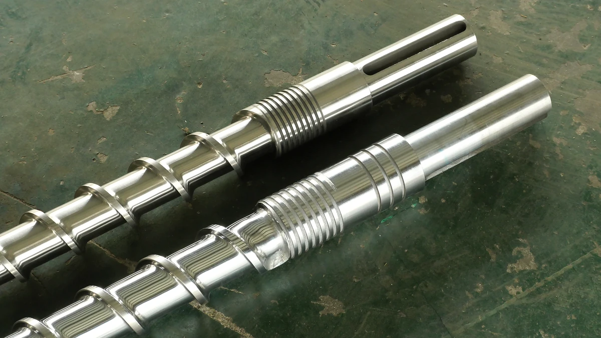
Why PP Extrusion Demands a Purpose-Built Screw and Barrel
Imagine swapping the engine tuned for a sports car into a heavy-duty truck and expecting peak performance from both. That is essentially what happens when a processor runs polypropylene through an extruder screw barrel for PP that was actually designed around polyethylene or polystyrene. The resin moves, yes — but the melt quality, output consistency, and part performance all suffer in ways that are surprisingly difficult to diagnose after the fact.
Why Polypropylene Is Not Just Another Polyolefin
PP belongs to the polyolefin family alongside HDPE and LDPE, yet its molecular architecture sets it apart in processing-critical ways. The methyl group attached to every alternate carbon on its backbone chain stiffens the molecule and raises the crystalline melting point to roughly 160 degrees C — about 30 degrees C higher than HDPE. Polypropylene is semi-crystalline, which means it stores a highly ordered internal structure that must be overcome at a sharp, well-defined melting point rather than softening gradually like amorphous polystyrene. That sharp melt transition creates a narrow processing window where the screw barrel must deliver enough energy to fully melt every pellet without pushing the polymer into thermal degradation territory.
PP also carries a chemical vulnerability its polyethylene cousins largely avoid. The tertiary carbon atom created by that same methyl group provides an active site for oxidative attack, making polypropylene inherently less thermally stable than PE. Where PE tends to cross-link under excessive heat or peroxide exposure, PP undergoes chain scission — the polymer chains literally break apart, reducing molecular weight and destroying melt strength.
How PP's Thermal and Rheological Behavior Affects Screw Design
Two characteristics dominate screw barrel engineering for polypropylene: its relatively low melt viscosity and its strong sensitivity to shear heating. PP's low viscosity at processing temperatures means the melt flows easily, which sounds like an advantage. In practice, however, it means the polymer generates less internal resistance to screw rotation. As Jim Frankland of Plastics Technology explains, the energy that heats polymer inside an extruder comes primarily from the mechanical shearing action between the screw and barrel bore — not from the barrel heaters themselves. A lower-viscosity melt absorbs less shear energy per revolution, so the screw geometry must compensate to achieve complete melting without simply cranking up speed and overheating the resin.
Polypropylene's pseudoplastic behavior further complicates things. Its viscosity drops sharply at higher shear rates, which enhances mold-filling in injection applications but can create uneven melting inside extruder barrels if the channel depths and compression rate are not matched to this rheological profile. A screw designed for a higher-viscosity polymer like HDPE will subject PP to excessive residence time or localized overheating in the metering zone, triggering the chain scission that PP is already prone to.
A screw optimized for HDPE can cause melt degradation or surging when processing PP due to fundamental differences in melting behavior and melt strength.
The Cost of Using a General-Purpose Screw for PP
There is no truly "universal" extrusion screw — and the reasons go far beyond marketing. Polymer-specific properties such as solid and melt density, heat of fusion, coefficient of friction, and viscosity response to shear all dictate how the feed zone, compression zone, and metering zone should be proportioned. HDPE, for instance, requires roughly 50 percent more energy input than HIPS to reach processing temperature once its heat of fusion is accounted for. PP sits in a different thermal neighborhood altogether, with its own unique balance of crystallinity, melt density change, and shear sensitivity.
Running PP on a screw sized for PE often produces extruder screw wear issues over time — not because PP is abrasive, but because the mismatch forces operators to compensate with higher temperatures or pressures that accelerate degradation and create unsteady flow. Surging, gels, inconsistent gauge, and premature yellowing are common symptoms. Each of these defects traces back to the same root cause: the extruder feed barrel and downstream zones were never engineered around polypropylene's specific melting and flow behavior.
Getting the screw barrel right for PP is not a luxury reserved for high-volume processors. It is the single most impactful variable separating a stable, efficient line from one that constantly chases quality problems. The question, then, is exactly what geometry, materials, and design features that screw and barrel should have — and how those specifications shift across the wide range of PP grades processors actually run.
PP-Specific Screw Geometry and Dimensional Recommendations
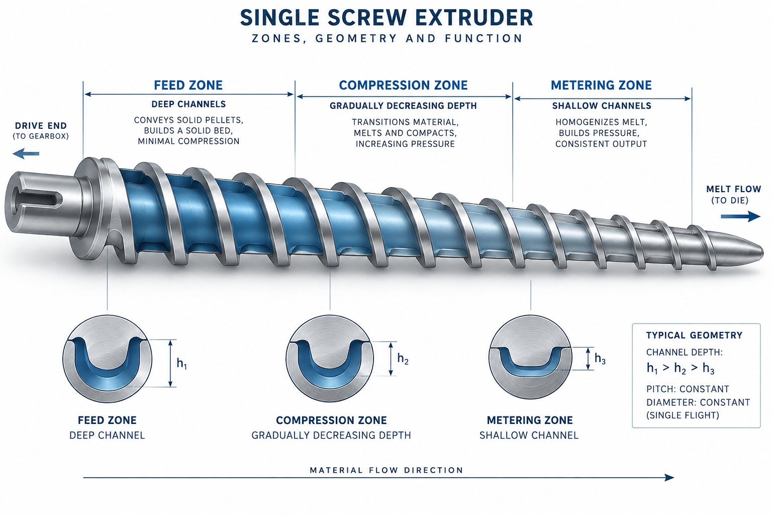
Every extruder screw is ultimately defined by a handful of dimensional parameters — but the values that work for one polymer can quietly wreck melt quality for another. Polypropylene's sharp melt transition, low melt viscosity, and tendency toward chain scission under heat all impose tight constraints on how those dimensions should be set. Here is what PP actually needs from its screw geometry, and why generic numbers borrowed from PE or PS processing fall short.
Optimal L/D Ratio and Compression Ratio for PP Screws
The length-to-diameter ratio — the ratio of the screw's effective working length to its outer diameter — governs how long polymer pellets spend inside the extrusion barrel and how much cumulative shear heating they absorb. For polypropylene, the practical sweet spot sits between 24:1 and 30:1. A ratio below 24:1 often leaves PP pellets incompletely melted, especially at higher throughput rates, because there simply is not enough screw length to transfer sufficient energy through the resin's sharp crystalline melt point. Push the ratio much beyond 30:1, however, and the extended residence time exposes PP to the very thermal degradation it is so vulnerable to. As single screw design principles confirm, excessively long L/D configurations cause prolonged material residence that leads to thermal decomposition of heat-sensitive polymers — and PP sits firmly in that category.
Compression ratio — the volume change between the feed section and the metering section of the extruder screw — is equally critical. For unfilled PP homopolymer and copolymer, a compression ratio in the 2.5:1 to 3.5:1 range is generally recommended. This range provides enough compaction and shear to fully melt the crystalline structure without generating the localized hot spots that trigger chain scission. PP's low melt viscosity means it cannot absorb intense shear energy the way higher-viscosity materials like ABS or PC can, so the compression must be gradual rather than aggressive. Filled PP compounds, particularly those loaded with glass fiber or mineral fillers at 20 percent and above, may warrant a compression ratio at the lower end of this range — or even slightly below — to minimize filler breakage and reduce abrasive wear on screw flights.
Feed Zone, Compression Zone, and Metering Zone Channel Depths
Think of the three screw zones as a carefully staged energy delivery system. Each zone's channel depth determines how much polymer sits between the screw root and the barrel wall, which directly controls shear rate and heat generation at that point along the screw.
In the feed zone, PP benefits from relatively deep channels. Deep feed channels maximize solids conveying capacity and keep the still-solid pellets moving forward without generating premature frictional heat. Because PP pellets are lighter and less dense than HDPE pellets, a starved or shallow feed section can cause inconsistent solids intake that shows up downstream as output surging.
The compression zone is where channel depth gradually decreases — and for PP, the word "gradually" matters enormously. A screw channel depth that decreases too abruptly forces the semi-crystalline pellets through their narrow melt transition in too short a distance, creating a mix of unmelted solids surrounded by overheated melt. PP's sharp melting point means there is very little temperature range between "still solid" and "fully molten," so the compression zone must be long enough to allow orderly melting across the entire bed. A compression zone occupying roughly 25 to 35 percent of the total screw length works well for most PP grades.
The metering zone demands the shallowest channels — but for PP, shallower than you might expect relative to PE screws. Shallow metering depths increase shear rate, which for PP's already-low melt viscosity serves to homogenize the melt without requiring high screw speeds. The trade-off is that excessively shallow metering channels can spike melt temperature beyond PP's degradation threshold. A metering channel depth that balances adequate shear mixing against thermal sensitivity is essential. Typical metering depths for PP single screws fall shallower than those used for HDPE but not as shallow as those common in PVC processing.
Flight Geometry and Its Impact on PP Melt Conveyance
Beyond channel depths and compression ratios, the flight geometry itself influences how efficiently the extruder screw moves PP melt forward. Two parameters deserve particular attention: flight width and helix angle.
Flight width — the land area at the top of each screw flight — directly affects the clearance between flight and barrel bore. For PP, standard flight widths of approximately 10 percent of the screw diameter work well in most cases. Wider flights increase barrel-side shear in the clearance gap, which generates additional heat in a polymer that already struggles with thermal stability. Narrower flights reduce that clearance shear but sacrifice some pressure-building capability and can accelerate wear.
Helix angle, or pitch angle, controls the balance between forward conveyance and cross-channel circulation. Research into melt conveying in single-screw extruders demonstrates that increasing the helix angle intensifies transverse flow and raises viscous dissipation — both of which push melt temperatures higher. For PP's thermally sensitive profile, a standard square-pitch design (helix angle near 17.66 degrees) provides a reliable baseline. Deviations toward steeper pitches should be approached cautiously, because the additional shear heating can outpace PP's ability to tolerate it without degradation. In twin screw barrel configurations used for compounding PP, the kneading and conveying element arrangement similarly must balance mixing intensity against thermal exposure.
| Parameter | PP Homopolymer | PP Copolymer (Random / Impact) | Filled PP (Glass or Mineral) |
|---|---|---|---|
| L/D Ratio | 24:1 – 28:1 | 26:1 – 30:1 | 28:1 – 32:1 |
| Compression Ratio | 2.5:1 – 3.5:1 | 2.5:1 – 3.0:1 | 2.0:1 – 3.0:1 |
| Feed Zone Depth | Deep — maximize solids conveying | Deep — accommodate lower bulk density | Deep — handle high filler loading |
| Compression Zone Length | 25 – 30% of screw length | 28 – 35% of screw length | 30 – 35% of screw length |
| Metering Zone Depth | Relatively shallow | Moderate — balance mixing and thermal sensitivity | Moderate — reduce filler damage |
| Flight Width | ~0.10 x screw diameter | ~0.10 x screw diameter | ~0.10 x screw diameter (hardened) |
| Helix Angle | Square pitch (~17.66°) | Square pitch (~17.66°) | Square pitch or slightly reduced |
Note: Ranges reflect general plastics engineering principles. Verify specific values against resin supplier datasheets and your equipment manufacturer's recommendations for your exact PP grade and process conditions.
Geometry alone, however, only tells part of the story. The same screw dimensions perform very differently depending on whether the PP compound running through them is a neat homopolymer, a rubber-modified impact copolymer, or a glass-filled formulation carrying 30 percent or more reinforcing fiber. Each of these grade variants shifts the wear, melting, and mixing demands placed on the screw and the extrusion barrel in ways that the numbers above can only approximate.
How PP Grade Variants Change Screw and Barrel Requirements
Polypropylene is not a single material — it is a family. A processor running neat PP homopolymer for thermoforming sheets faces a completely different barrel extruder wear profile and screw design challenge than one compounding 40 percent glass-fiber-reinforced impact copolymer for automotive bumper fascias. Yet screw and barrel replacements are routinely ordered as though "PP" were one monolithic resin. That oversimplification quietly destroys melt quality, shortens equipment life, and inflates production costs across the board.
Understanding how each PP grade variant shifts the demands on your screw plastic extruder setup is essential before specifying any replacement hardware. Here is a breakdown of the six most common PP types processors encounter — and what each one actually needs from the screw and barrel.
- PP Homopolymer (H-PP): Highest stiffness and crystallinity; least demanding on barrel wear but most sensitive to thermal degradation via chain scission.
- Random Copolymer (PP-R): Contains up to 6 percent ethylene comonomer; lower melting point and reduced crystallinity require gentler thermal profiles and slightly less compression.
- Impact Copolymer (ICP): Heterophasic structure with a dispersed rubber phase; demands enhanced mixing sections to achieve uniform rubber distribution without overheating the PP matrix.
- Glass-Fiber-Filled PP: Extremely abrasive at 20–40 percent loading; dramatically accelerates flight and bore wear, requiring hardened or bimetallic components.
- Talc-Filled PP: Moderately abrasive with finer particle action; creates gradual adhesive and erosive wear patterns distinct from glass fiber.
- Calcium-Carbonate-Filled PP (CaCO3): Used at high loading percentages (sometimes up to 80 percent in masterbatch); softer than glass but generates significant cumulative wear at elevated concentrations.
Homopolymer vs Random Copolymer vs Impact Copolymer
When you process unfilled PP homopolymer, the screw and barrel face minimal abrasive stress. The resin contains no reinforcing fibers, no mineral particles, and no hard additives grinding against metal surfaces. This makes H-PP the gentlest grade on equipment — but also the most unforgiving when it comes to thermal management. Homopolymer's high crystallinity (typically 50 to 70 percent) concentrates its melt transition into a narrow temperature band. Push the melt even slightly beyond this window, and the tertiary carbon sites along the backbone chain become oxidation targets. The result is molecular weight loss, reduced melt strength, and visible yellowing. For H-PP, the priority is precise temperature control in the metering zone and a compression ratio that avoids localized shear spikes — not wear resistance.
Random copolymer introduces a different set of considerations. The small percentage of ethylene units randomly inserted along the PP chain disrupts the crystalline structure, lowering the melting point by roughly 10 to 15 degrees C compared to homopolymer. This broader, somewhat less defined melt transition actually provides a slightly wider processing window, but it also means the resin softens earlier in the compression zone. Screws designed strictly around homopolymer melt points can overshear random copolymer, generating excess heat in a resin that is already flowing at a lower temperature. Slight reductions in compression ratio and careful attention to barrel zone temperatures in the transition section help keep PP-R within its comfort zone.
Impact copolymer is where the complexity ramps up significantly. As the USEON polypropylene processing guide explains, ICP features a heterophasic structure — an ethylene-propylene rubber phase dispersed within a homopolymer PP matrix. This rubber phase does not melt in the conventional sense; instead, it must be uniformly distributed throughout the PP melt to deliver the impact resistance the grade is designed for. A standard metering-zone-only mixing approach often leaves rubber domains poorly dispersed, creating weak spots in the finished product. Impact copolymer typically benefits from screws equipped with dedicated distributive mixing elements that stretch and fold the melt without relying on the high-shear intensity that would overheat the PP matrix surrounding the rubber particles.
Glass-Fiber-Filled PP and Accelerated Abrasive Wear
Glass-fiber-reinforced PP is arguably the most punishing grade any screw and barrel will face in the polypropylene family. At fiber loadings of 30 to 40 percent — common in automotive and structural applications — every revolution of the screw drags millions of hard, abrasive glass filaments across the flight lands and barrel bore. The wear mechanism is predominantly abrasive: the glass fibers act like fine cutting tools, progressively eroding the flight outside diameter and widening the barrel bore clearance.
The consequences compound quickly. As Santa Fe Machine Works documents, filled polymers containing glass fibers or mineral reinforcing agents cause increased wear on the screw surface due to abrasive action during the plasticating process. The widening flight-to-bore clearance reduces the screw's ability to generate consistent pressure, leading to output variation and diminished melt homogeneity. What might take years of gradual wear with unfilled PP can happen in months with heavily glass-filled compounds.
Screw and barrel material selection for glass-filled PP is not optional — it is mandatory. Standard nitrided barrels erode too quickly to be economical. Bimetallic barrel linings, combined with tungsten carbide hardfacing or similar wear-resistant coatings on screw flights, become baseline requirements. Additionally, screws for glass-fiber-filled PP often benefit from lower compression ratios and gentler mixing sections. Aggressive kneading blocks or high-shear mixing elements break the fibers, reducing the average fiber length and degrading the mechanical properties that justified choosing the filled grade in the first place. As USEON's compounding engineers recommend, specialized distributive mixing elements — toothed blocks rather than aggressive kneading blocks — preserve fiber integrity while still achieving acceptable dispersion. Twin screw and barrel configurations are frequently preferred for glass-fiber compounding specifically because their modular design allows precise tuning of mixing intensity along the barrel length.
Talc-Filled and Mineral-Filled PP Compounds
Mineral fillers like talc and calcium carbonate present a different wear equation than glass fiber, and treating them identically is a common mistake. Talc particles are platy and relatively soft compared to glass, with a Mohs hardness around 1, while glass fiber rates around 6.5. CaCO3 sits in between at roughly 3 on the Mohs scale. Despite these lower hardness ratings, mineral fillers still cause meaningful wear — just through different mechanisms.
Talc-filled PP at loadings of 20 to 40 percent tends to produce a combination of adhesive wear and fine erosive wear on screw flights. The platy particle shape means talc does not gouge the metal surface the way a glass fiber does. Instead, the fine particles create a gradual polishing and erosion effect that slowly opens flight clearances over thousands of operating hours. The wear pattern is more uniform and less dramatic than glass-induced damage, which makes it easy to overlook until output consistency starts declining.
Calcium carbonate, especially at the very high loadings used in filler masterbatch production — sometimes reaching 60 to 80 percent — creates its own unique challenge. At these concentrations, the compound behaves less like a polymer melt and more like a mineral slurry with a polymer binder. The sheer volume of hard particles in contact with metal surfaces generates cumulative abrasive wear that, over time, rivals the severity of lower-percentage glass-fiber compounds. USEON notes that their high-loading CaCO3 masterbatch lines rely on bimetallic barrels specifically to resist this abrasion, along with split-feeding strategies that introduce the abrasive filler downstream rather than subjecting the entire barrel length to mineral contact.
For processors running mineral-filled PP, the practical takeaway is straightforward: standard nitrided steel may suffice at filler loadings below 15 to 20 percent, but anything above that threshold warrants a serious evaluation of barrel liner upgrades and screw flight surface treatments. The wear may be slower than glass fiber, but it is relentless — and the cost of ignoring it compounds with every production run.
Each of these grade-specific wear patterns and processing demands feeds directly into material selection for the barrel and screw themselves. Choosing the right alloy, coating, or liner is not a separate decision from choosing the right geometry — it is the other half of the same engineering equation.
Barrel and Screw Material Selection for PP Compounds
Geometry defines how a plastic extruder screw moves and melts polypropylene. Metallurgy decides how long it keeps doing so accurately. A perfectly dimensioned screw with the ideal compression ratio and channel depths will still fail prematurely if its base metal, surface treatment, or barrel liner cannot withstand the specific wear environment created by the PP compound running through it. The previous section mapped how each PP grade variant — from neat homopolymer to 40 percent glass-filled formulations — creates distinct wear demands. This section answers the logical follow-up: which metals, alloys, and coatings actually meet those demands?
When Nitrided Steel Is Sufficient for PP Processing
Nitriding remains the most common and cost-effective surface hardening treatment for extrusion screws and barrels processing unfilled polymers. The process diffuses nitrogen into the steel surface, creating a case-hardened layer roughly 0.015 to 0.020 inches deep with a hardness of approximately 60 HRC. For unfilled PP homopolymer and random copolymer, this level of protection is typically more than adequate. These neat resins contain no abrasive particles, no reinforcing fibers, and minimal hard additives — so the primary wear mechanisms are corrosive attack from stabilizer packages and the slow adhesive friction of polymer melt against steel.
Nitrided barrels paired with nitrided screws can deliver years of reliable service on unfilled PP lines, making them a sensible default choice when cost control matters and the resin formulation stays clean. There is, however, a critical limitation to keep in mind. The hardened case is thin — just fifteen to twenty thousandths of an inch. Once abrasive wear penetrates that shell, the softer base metal underneath erodes rapidly. As industry documentation from SpecialChem's composites processing guide warns, the transition from protected to unprotected steel happens without warning, and the base metal can erode "like a hot knife through butter" once exposed. This makes nitrided components a poor long-term choice the moment fillers or reinforcements enter the compound — even at modest loading percentages.
For processors who occasionally switch between unfilled and lightly filled PP grades on the same screw extruder, nitriding buys time but not insurance. Regular screw pulls and visual inspections become essential to catch wear before it crosses the nitrided boundary layer.
Bimetallic Barrels for Filled and Reinforced PP
When talc, calcium carbonate, or glass fiber enters the PP formulation at meaningful loading percentages — generally above 15 to 20 percent — the wear equation changes fundamentally. Filler particles scraping against the barrel bore create abrasive wear patterns that chew through nitrided surfaces far too quickly to be economical. This is where bimetallic barrel construction earns its place.
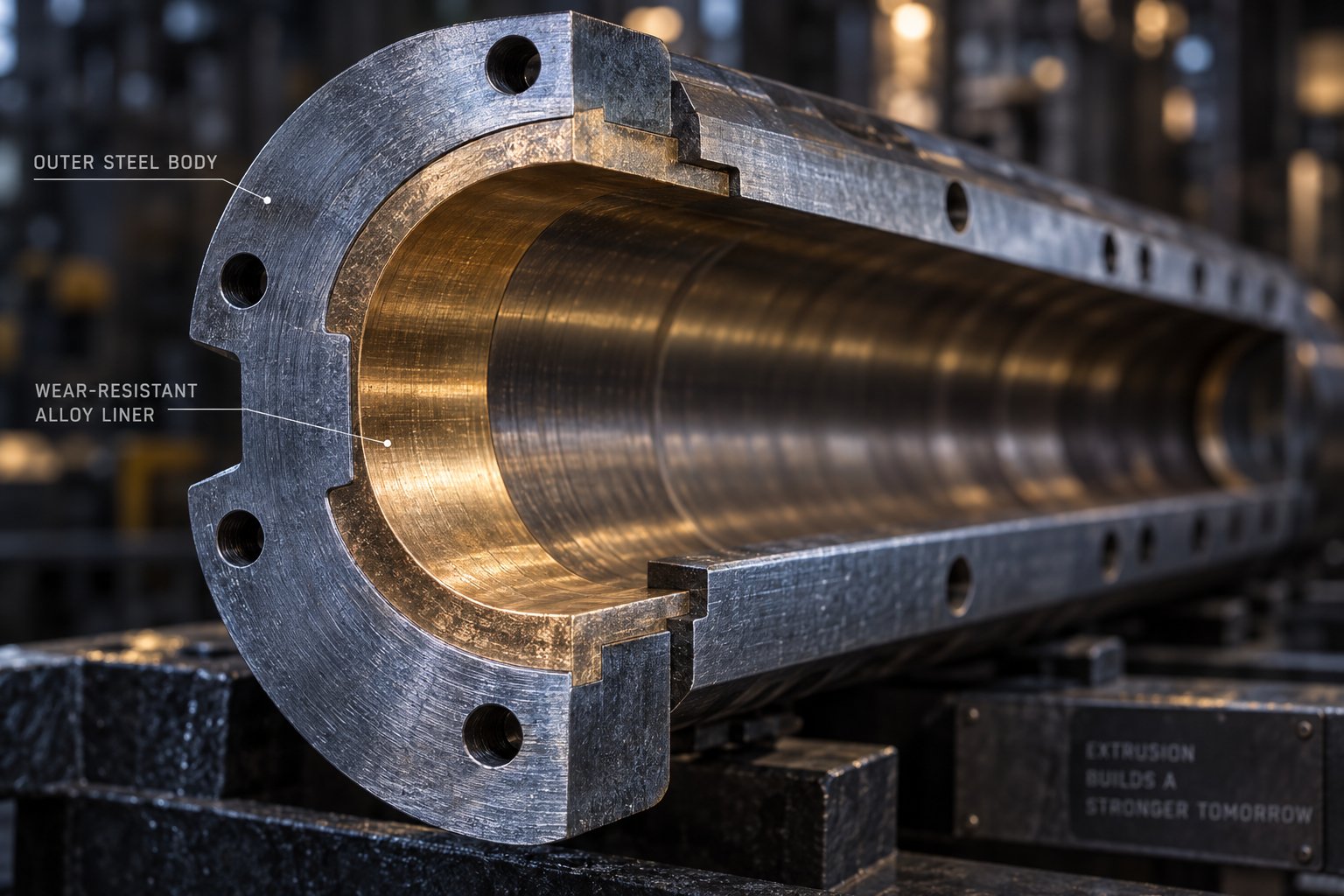
A bimetallic barrel uses a centrifugal spin-casting process to bond a wear-resistant alloy liner onto the inner bore of the steel barrel body. The result is a barrel with the structural strength of carbon steel on the outside and a hard, abrasion-resistant lining on the inside — exactly where filler contact is most aggressive. Modern bimetallic liners can incorporate tungsten carbide particles suspended in the base alloy matrix, a technology that increases barrel life by four to five times compared to earlier-generation bimetallic liners. For heavily glass-filled PP at 30 to 40 percent loading, this level of protection transforms what would be a quarterly barrel replacement issue into a manageable annual inspection cycle.
Common bimetallic liner alloys fall into two broad categories based on the dominant wear mechanism:
- Abrasion-resistant alloys: Boron-based and tungsten-carbide-enhanced liners designed primarily for glass-fiber and mineral-filled PP where hard particles physically cut and erode the bore surface.
- Corrosion-resistant alloys: Nickel-based liners intended for PP compounds that contain flame retardants, acidic stabilizers, or halogenated additives that chemically attack the barrel surface.
Some PP formulations — particularly flame-retardant impact copolymer grades used in electrical housings — create both abrasive and corrosive wear simultaneously. For these dual-threat compounds, combination alloy liners offering balanced resistance to both mechanisms provide the best service life. Selecting the wrong liner category is a surprisingly common specification error that leads to premature failure despite the significant investment in bimetallic construction.
Screw Surface Treatments and Hardfacing Options
Barrel upgrades alone solve only half the problem. The extrusion screw flights, particularly in the feed and early compression zones where polymer is still in pellet form, endure direct contact with abrasive filler particles before a protective melt film develops. Several surface treatment and hardfacing strategies address this vulnerable area, each targeting a different wear mechanism and budget threshold.
Flame hardening provides a relatively economical improvement over untreated steel. It increases surface hardness on flight lands and the screw root, but the hardened depth is limited and the improvement modest compared to other methods. Flame hardening suits low-filler PP applications where some added durability is desired without the cost of full hardfacing.
Chrome plating adds a thin, hard surface layer that resists corrosive wear and reduces polymer adhesion. It is particularly useful for PP grades containing corrosive additives or where melt stagnation and degradation on screw surfaces are concerns. Chrome plating, however, offers limited resistance to heavy abrasive wear from glass fibers — the plating is simply too thin to withstand sustained particle contact.
Tungsten carbide hardfacing represents the most robust protection available for screw flights processing filled PP. Applied through methods like High Velocity Oxy-Fuel (HVOF) thermal spray or spray welding and fusion, tungsten carbide coatings achieve hardness values in the range of 68 to 71 HRC (940 to 1076 HV), far exceeding what nitriding or chrome plating can deliver. For glass-fiber-filled PP, tungsten carbide hardfacing on the flight OD and — in severe cases — full root encapsulation with a carbide-loaded alloy is the standard recommendation. The encapsulation method machines the original screw channel deeper than the final geometry and then builds the root and flight sides back up with harder material, providing protection exactly where abrasive fillers do the most damage in the feed and transition zones.
For processors weighing these options, the decision ultimately maps to the PP compound type and filler loading. The table below summarizes the alignment between material choices and typical PP processing scenarios:
| Component / Treatment | Unfilled PP (Homopolymer, Copolymer) | Talc- or CaCO3-Filled PP (15–40%) | Glass-Fiber-Filled PP (20–40%) |
|---|---|---|---|
| Nitrided Steel Barrel | Sufficient — good service life with regular inspection | Marginal — acceptable only at lower filler loadings with frequent monitoring | Not recommended — rapid bore wear at typical glass loadings |
| Bimetallic Barrel (Abrasion-Resistant Liner) | Not typically necessary — cost not justified | Recommended above 20% loading for extended barrel life | Essential — tungsten-carbide-enhanced liners preferred |
| Bimetallic Barrel (Corrosion-Resistant Liner) | Needed only with corrosive additive packages (e.g., flame retardants) | Consider if compound includes corrosive additives alongside filler | Consider combination liner if corrosive additives are present |
| Nitrided Screw | Sufficient for standard service | Short-term solution — monitor for case breakthrough | Inadequate — case wears through too rapidly |
| Chrome-Plated Screw | Useful against corrosive wear and melt sticking | Limited abrasion benefit — better suited to corrosive environments | Not sufficient as sole protection against glass abrasion |
| Tungsten Carbide Hardfaced Screw | Rarely needed — overspecified for unfilled PP | Recommended for flight lands at higher mineral loadings | Essential — full flight hardfacing and consider root encapsulation |
Note: Recommendations reflect general engineering principles. Actual service life depends on screw speed, output rate, specific filler particle characteristics, and maintenance practices. Consult your screw barrel manufacturer for compound-specific guidance.
Getting the metallurgy right protects your investment in the correct screw geometry — but even the best-specified, hardest-coated screw still depends on what happens inside the melt itself. How the polymer is mixed, how uniformly it melts across the barrel cross-section, and how pressure is maintained at the screw tip all determine whether that PP melt arrives at the die in a condition worth extruding.
Mixing Elements and Barrier Flights for PP Melt Homogeneity
A perfectly hardened screw flight riding inside a precisely lined barrel still produces defective PP parts if the melt leaving the screw tip is thermally uneven or riddled with unmixed domains. Melt homogeneity — uniformity of temperature, composition, and viscosity across the entire melt stream — is where mixing elements, barrier flight concepts, and screw tip geometry earn their keep. For polypropylene, this is an especially delicate balancing act. PP's low melt viscosity means it flows easily but generates less internal friction, so mixing must be intentionally engineered into the screw rather than left to chance. At the same time, every additional mixing element extends residence time and adds shear energy — both of which push a thermally sensitive resin closer to degradation.
For polypropylene, mixing element selection is always a balance between achieving melt homogeneity and avoiding the residence-time-driven degradation that PP's thermal sensitivity invites.
Mixing Element Types Suited to PP's Low Melt Viscosity
Mixing elements fall into two broad functional categories: dispersive and distributive. Dispersive mixers break down agglomerates, gels, or incompletely melted particles by subjecting them to high shear stress. Distributive mixers spread material uniformly throughout the melt stream without relying on intense shearing forces. For most PP processing — particularly unfilled and impact copolymer grades — distributive mixing is the higher priority, because the polymer's low melt viscosity means that excessive dispersive shear simply converts to unwanted heat rather than productive mixing work.
Three mixing element types appear most frequently in injection molding screws and barrels as well as extrusion screws designed for polypropylene:
- Maddock-style (fluted) mixers: These are dispersive mixers consisting of alternating inlet and outlet channels separated by barrier lands. Polymer is forced over the barrier land, exposing it to a controlled shear gap. For PP, Maddock mixers work well for eliminating residual unmelts and gels, but their fixed-clearance design means the shear rate is largely determined by screw speed. Running a Maddock section too fast on PP quickly overheats the melt. Properly sized, however, a Maddock mixer positioned near the discharge end of the screw provides an effective final quality check on melt uniformity.
- Pineapple mixers: Named for their textured surface resembling a pineapple skin, these elements split and recombine the melt stream repeatedly through a pattern of diamond-shaped channels. Their action is primarily distributive, making them well-suited to PP's need for gentle but thorough blending. Pineapple mixers add relatively little shear heat compared to dispersive designs, which is a significant advantage for a resin prone to chain scission. They are commonly used in single-screw applications where color dispersion or additive distribution matters more than breaking apart hard agglomerates.
- Distributive mixing elements (toothed or slotted designs): These include elements like toothed mixing rings and slotted flight sections that repeatedly divide and recombine melt streams. Research from Paderborn University demonstrated that toothed mixing elements (ZME) outperformed kneading blocks for both distributive and dispersive mixing quality in twin-screw compounding, while also generating more uniform shear stress distributions across the melt. For PP, this matters because a uniform shear field means fewer localized hot spots — exactly the kind of thermal consistency that prevents degradation. In twin screw barrel setups used for PP compounding, toothed elements are increasingly preferred over aggressive 90-degree kneading blocks for this reason.
The choice between these mixer types — or combinations of them — depends on the specific PP grade and application. Unfilled homopolymer destined for sheet extrusion may need only a simple pineapple or distributive section for color uniformity. Glass-filled impact copolymer, by contrast, may require a carefully sequenced combination of a short dispersive section to eliminate gels followed by a distributive section to homogenize the rubber phase — all without breaking glass fibers or overheating the matrix. A reputable screw barrel manufacturer will typically recommend mixer configurations tailored to both the PP grade and the end application rather than defaulting to a one-size-fits-all layout.
Barrier Flight Designs for Uniform PP Melting
Mixing elements handle what happens after the polymer is molten. Barrier flights address an equally critical upstream problem: how uniformly the solid pellets transition to melt in the first place. PP's sharp crystalline melting point makes this transition particularly abrupt. In a conventional single-flight screw, the solids bed can fracture and disperse unmelt fragments into the melt pool, sending partially solid chunks downstream where they appear as gels or unmelts in the finished product.
Barrier screw designs solve this by introducing a secondary flight — the barrier flight — that physically separates the solids channel from the melt channel. Molten PP crosses over the barrier clearance into the melt channel, while still-solid pellets remain trapped in the solids channel until they fully melt. The concept dates to the Maillefer patent of the 1960s, but the most widely adopted commercial version is the Schippers/Barr barrier design, which uses a primary channel that gets progressively shallower as the adjacent auxiliary melt channel deepens. This geometry increases the total melting area in contact with the barrel wall compared to the original Maillefer approach, boosting melting capacity significantly.
Why does this matter specifically for PP? Because polypropylene's narrow melt transition leaves almost no margin for incomplete melting. In a conventional screw, if solids-bed breakup occurs — a well-documented phenomenon where internal melt pressure fractures the remaining solids — those unmelted fragments disperse into the metering zone and arrive at the die as visible defects. A barrier flight prevents this by physically containing the solids until they are fully converted to melt. For high-output PP lines, particularly in blown film and pipe extrusion, barrier screws have become the standard precisely because they deliver the melting uniformity that PP's sharp melt point demands.
Screw tip design also plays an often-overlooked role in maintaining the melt quality that barrier flights and mixing elements work so hard to achieve. The screw tip — the nose cone and any associated check valve or non-return assembly — must minimize dead spots where PP melt can stagnate. Even brief stagnation at processing temperatures gives polypropylene's oxidation-prone chain structure enough time to degrade, producing black specks, gels, or discolored streaks. Streamlined screw tip profiles with smooth flow paths and minimal recirculation zones help maintain pressure consistency at the extruder terminals while preventing the melt stagnation that ruins PP part quality from the inside out.
Screw Speed, Back Pressure, and PP Melt Quality
Imagine you have the ideal screw geometry, the right mixing elements, and a proper barrier section — yet the PP melt still shows temperature inconsistency and occasional gels. The culprit is often the operating parameters rather than the hardware itself. Screw speed and back pressure interact with PP's thermal sensitivity in ways that catch many processors off guard.
Higher screw speed generates more shear energy per unit time. For polymers with high melt viscosity, this additional energy efficiently converts to productive melting work. PP's low viscosity, however, means much of that energy converts directly to heat rather than useful mixing action. The Paderborn University study on twin-screw mixing elements confirmed that increasing rotation speed from 200 to 400 rpm shifted shear stress distributions higher and improved distributive mixing indices — but also substantially increased the shear stress integral over residence time. For a thermally robust polymer, that trade-off is manageable. For PP, it means the melt temperature climbs with every RPM increase, and beyond a certain threshold, you are simply degrading the resin faster than you are improving homogeneity.
This is why experienced PP processors often find that their optimal screw speed is lower than what the machine is capable of — and lower than what they would use for HDPE on the same equipment. Pushing for maximum output by maximizing screw speed is a strategy that works only until the melt temperature exceeds PP's degradation onset, at which point output may increase but part quality collapses.
Back pressure — the resistance applied to the screw during recovery in injection molding, or system pressure in extrusion — adds another layer of control. As Fimmtech's backpressure optimization research demonstrates, adequate back pressure compresses the melt, expels trapped volatiles from the transition zone, and improves melt density consistency from shot to shot. For PP, these benefits are real and important. Insufficient back pressure often manifests as splay, inconsistent part weights, or uneven shrinkage — all symptoms of a melt with trapped air and variable density.
The danger lies in overcorrection. Excessive back pressure extends residence time inside the barrel, which for PP means more time at elevated temperatures with more opportunity for chain scission. It also increases the shear work performed on the melt during recovery, further raising melt temperature. The practical approach is to use the minimum back pressure that delivers consistent melt density and eliminates splay — and then stop. For a davis standard single screw extruder or any comparable platform, this typically means running PP at lower back pressure settings than would be standard for HDPE or ABS, then verifying consistency through shot weight studies rather than relying on rules of thumb carried over from other resins.
The interplay between screw speed, back pressure, and PP melt quality reinforces a central theme: every parameter that adds energy to the melt must be weighed against polypropylene's limited ability to absorb that energy without degrading. The hardware — mixing sections, barrier flights, screw tip profiles — sets the upper limit of what is achievable. The operating parameters determine whether you actually reach that limit or overshoot it into degradation territory. Neither hardware nor process settings can be optimized in isolation, and both must be calibrated against the specific barrel zone temperature profile that controls how and where energy enters the PP melt.
Barrel Zone Temperature Profiles Optimized for PP
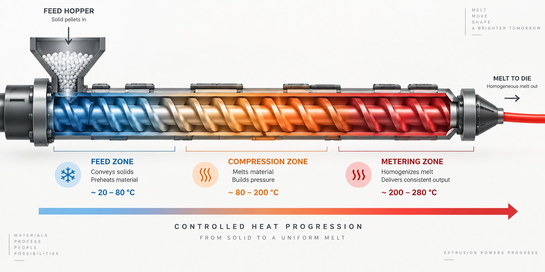
Barrel zone temperatures are where screw geometry, metallurgy, and mixing design either come together or fall apart. You can have the perfect compression ratio, the right barrier flights, and a properly hardened barrel liner — but if the temperature profile feeding energy into the PP melt is wrong, none of those investments deliver their full value. Polypropylene's melting point sits around 320 to 329 degrees F (160 to 165 degrees C), which is substantially higher than LDPE or HDPE yet low enough that even modest overheating triggers the chain scission PP is infamous for. That narrow window between "not yet melted" and "already degrading" makes temperature profiling for polypropylene a precision exercise rather than a rough guideline.
Feed Throat Cooling and Feed Zone Settings for PP
The temperature story for PP starts before the barrel heaters even come into play — at the feed throat. As Graham Engineering's feed section analysis details, the feed throat on most single-screw extruders is actively cooled, typically in the 90 to 120 degrees F range, to prevent premature softening of pellets on the barrel wall. For polypropylene, this cooling is especially critical. PP pellets have a relatively low coefficient of friction against steel, and any premature melting at the feed throat creates a sticky film that causes pellets to bridge — clumping together and restricting material flow into the screw channels. A bridged feed throat does not just reduce output; it creates cyclic starvation that shows up downstream as pressure surging and inconsistent melt temperature.
Why does PP need a cooler feed zone than PE? The answer traces back to the same semi-crystalline behavior discussed earlier. PP's sharp melt transition means there is almost no gradual softening phase — pellets go from solid to molten in a narrow temperature band. If heat from the compression zone migrates upstream into the feed section, PP pellets begin sticking to the barrel wall before the screw flights can convey them forward. HDPE, with its broader softening range and higher coefficient of friction against steel, tolerates warmer feed zones without bridging. PP does not.
The feed zone barrel heater itself should be set well below PP's crystalline melting point — warm enough to assist solids conveying through controlled friction, but cool enough to prevent any surface melting on the pellets. Exact setpoints vary by machine size, screw speed, and resin grade, so you will want to consult your resin supplier's processing datasheet for the specific PP you are running. As a general principle, think of the feed zone as a conveyor, not a heater — its job is to move pellets reliably, not to start melting them.
Compression and Metering Zone Temperature Strategy
The compression zone is where the real melting work begins, and for PP, the temperature ramp through this section must be deliberate and controlled. A steep temperature jump between the feed zone and mid-barrel creates the same problem as an aggressive compression ratio in the screw geometry — it forces PP pellets through their sharp melt transition too abruptly, producing a mixture of overheated melt and unmelted solids. Gradual temperature increases across the compression zones give the screw geometry time to do its job, allowing the solid bed to melt uniformly against the barrel wall.
The metering zone is where temperature control becomes most consequential. Industry best practice sets the metering zone at or slightly above the polymer's melting point to ensure the melt is fully homogenized and ready for the die. For PP, "slightly above" is the operative phrase — pushing the metering zone too high invites the thermal degradation that polypropylene's molecular structure makes nearly inevitable once temperatures climb beyond the processing window. Even 10 to 15 degrees F of unnecessary overshoot in the metering zone can show up as yellowing, reduced melt strength, or increased gel counts in the finished product.
The adapter and die zones should generally match or sit marginally above the metering zone setpoint. This ensures smooth melt flow through the die without premature cooling that causes increased die pressure or melt fracture. Avoid the temptation to run the die significantly hotter than the metering section — for PP, that extra heat adds residence-time degradation risk at the exact point where the melt should be at its most stable.
Here is a step-by-step procedure for setting up a PP temperature profile from feed throat to die on screw extruders of any configuration:
- Set feed throat cooling to maintain a stable temperature in the 90 to 120 degrees F range, ensuring consistent water flow through the cooling jacket. Verify no hot spots develop near the barrel flange connection.
- Set the feed zone barrel heater well below PP's melting point — typically the lowest heated zone setpoint on the barrel. Reference your resin supplier's recommended feed zone range for the specific PP grade.
- Increase temperatures gradually across the compression zone heaters, stepping up in controlled increments toward the melting point. Avoid abrupt jumps between adjacent zones.
- Set the metering zone at or slightly above the PP melting point as specified on the resin datasheet — this is usually the highest barrel setpoint for PP extrusion. For most PP grades, barrel temperatures in this zone fall within the 180 to 250 degrees C (356 to 482 degrees F) range depending on formulation and output requirements.
- Match the adapter and die zone temperatures to the metering zone setpoint or set them marginally higher to maintain flow consistency through the die.
- Monitor actual melt temperature with a handheld pyrometer or melt thermocouple at the die exit. Barrel setpoints and actual melt temperature diverge — actual melt temperature reflects the combined effect of barrel heat and shear heating from the injection screw or extrusion screw. Adjust setpoints based on measured melt temperature, not just zone controller readings.
- Allow the system to stabilize for at least 20 to 30 minutes after any setpoint change before evaluating melt quality. PP's thermal response lags behind heater adjustments, and premature corrections often overshoot in both directions.
Adjusting Temperature Profiles for Filled PP Grades
Filled PP compounds — whether loaded with talc, calcium carbonate, or glass fiber — demand temperature profile adjustments that unfilled grades do not. Fillers act as thermal sinks within the melt, absorbing heat energy that would otherwise raise the polymer temperature. A temperature profile optimized for neat PP homopolymer may leave a 30 percent talc-filled compound insufficiently plasticized, producing high die pressures and inconsistent output.
The practical adjustment is straightforward: filled PP grades generally tolerate — and often require — slightly higher barrel temperatures across the compression and metering zones compared to their unfilled equivalents. The fillers absorb a portion of the thermal energy, effectively buffering the PP matrix against the localized overheating that causes degradation in neat resin. This gives you a marginally wider operating window, but it does not eliminate the degradation risk entirely. Glass-fiber-filled PP in particular demands careful attention, because the higher barrel temperatures needed to maintain adequate melt flow also increase the rate of fiber-induced shear heating. The combination can push melt temperatures above the safe processing window faster than operators expect.
For injection molding screws processing filled PP, the same principles apply with one additional consideration: recovery time. Filled compounds increase the torque demand on the injection screw during plasticating, and the higher energy input per revolution means the melt absorbs more shear heat even at the same screw speed. Reducing screw RPM slightly while maintaining or modestly increasing barrel zone temperatures often produces better results than trying to compensate for insufficient melting by pushing screw speed higher.
Temperature profiling is ultimately diagnostic as much as prescriptive. The setpoints you program into the controller are starting points informed by resin datasheets and experience. The actual melt temperature — measured, not assumed — tells you whether your barrel zones, screw geometry, and operating parameters are working together or fighting each other. When they fight, the symptoms appear as the very defects that send processors scrambling for answers: melt fracture, gels, surging, and discoloration — each of which traces back to specific screw and barrel conditions that a structured troubleshooting approach can identify and correct.
Troubleshooting PP Extrusion Defects Linked to Screw and Barrel
You have dialed in the temperature profile, selected the right metallurgy, and specified geometry suited to your PP grade — yet defects still show up on the finished product. Before blaming the resin batch or the downstream equipment, consider this: the majority of persistent PP extrusion defects trace directly back to the condition or design of the extruder screws and barrels themselves. A worn flight, an undersized mixing section, or a metering channel that has lost its original depth can produce symptoms that mimic material problems, die issues, or temperature control failures. Knowing which defect points to which screw or barrel condition saves hours of trial-and-error troubleshooting and prevents the costly habit of chasing symptoms instead of root causes.
Melt Fracture, Gels, and Unmelts Traced to Screw Design
Melt fracture in PP extrusion appears as a rough, shark-skin-like surface texture or rhythmic waviness on the extrudate. While die geometry and exit shear rate contribute, the screw side of the equation is often overlooked. When the metering zone delivers a thermally uneven melt stream — pockets of hotter, lower-viscosity material swirling alongside cooler, stiffer regions — the melt encounters wildly different shear stresses as it enters the die land. For PP's already low melt viscosity, even modest thermal non-uniformity amplifies this effect. Inadequate mixing sections or a metering zone that is too deep to generate sufficient homogenizing shear are frequent culprits. Adding or upgrading to a properly sized distributive mixer near the screw discharge can resolve melt fracture that no amount of die lip adjustment will fix.
Gels and unmelts present a related but distinct problem. Those small, translucent fish-eye defects embedded in PP sheet or film are particles of polymer that never fully melted — or that melted, degraded, and cross-linked into insoluble specks. As Mark Spalding of Dow documents, degraded resin commonly accumulates at flight radii where Moffatt eddies — recirculating flow patterns caused by undersized flight corner radii — trap material for extended periods at processing temperatures. For PP, which degrades through chain scission rather than cross-linking, these stagnant zones produce low-molecular-weight fragments that appear as gels or discolored specks. Increasing the flight radii to approximately 1.4 to 1.5 times the local channel depth eliminates Moffatt eddies for most resins. Worn screw flights compound the problem differently: as flight clearance increases due to wear, the screw's ability to generate compressive shear in the transition zone drops, allowing unmelted pellet fragments to survive into the metering section and reach the die. A finer screen pack (60/100/60 mesh or finer) catches some of these particles, but the real fix is restoring or replacing the extruder screw barrel to recover the original compression and shear characteristics.
Output Surging and Its Connection to Screw Wear
Surging — that rhythmic pulsation of output where the extrudate alternately thickens and thins — ranks among the most frustrating PP processing problems because it can originate from multiple points along the screw. When the surge frequency correlates with screw rotation, the problem almost certainly lives inside the barrel. Two screw-related mechanisms dominate.
The first is feed zone inconsistency. PP pellets have a relatively low coefficient of friction against steel, and any wear or thermal irregularity in the feed section reduces the screw's grip on incoming pellets. The result is intermittent solids conveying — the screw alternately grabs and slips on the pellet bed, sending pulses of material downstream. JWELL's troubleshooting engineers recommend checking feed throat cooling first, keeping it below 60 degrees C to prevent pellet softening and slip, and inspecting the hopper for bridging when running regrind blends.
The second mechanism is metering section wear. As the flight lands in the metering zone erode, the clearance between the screw flight OD and the barrel bore increases. This widening gap allows melt to leak backward over the flights — a phenomenon called backflow or pressure-flow leakage. The leakage is cyclic because it depends on the instantaneous pressure differential across each flight, which itself fluctuates with screw rotation. For PP, with its low melt viscosity, even modest clearance increases cause disproportionate leakage compared to higher-viscosity polymers. A screw pull to measure flight clearance is the definitive diagnostic step when surging persists after process adjustments have been exhausted.
Thermal Degradation from Barrel and Screw Conditions
Yellowing, black specks, brittleness, off-gassing, and reduced melt strength in PP parts all point toward thermal degradation — and the extruder screws are almost always implicated. The degradation pathway is straightforward: PP sits at elevated temperatures for too long, and its molecular chains break apart. But what creates that excessive residence time?
Oversized or worn screws are a primary offender. When metering channel depth increases due to wear, the effective volume of the metering section grows. More polymer sits inside the barrel at any given moment, and each particle takes longer to travel from hopper to die. That extra time at temperature is precisely what PP cannot tolerate. As Spalding's hot-screw-pull methodology reveals, degradation builds visibly at flight corners, mixer flutes, and any area where flow stagnation allows resin to cook. Maddock mixer flutes that are too deep relative to their width are a documented source of stagnation and degradation — a design flaw that can be corrected by ensuring flute width is at least twice the flute depth.
Unplanned shutdowns amplify the problem dramatically. If the barrel heaters remain at processing temperatures during downtime, the stationary PP melt degrades across the entire metering section within minutes. Standard practice for PP is to reduce barrel temperatures promptly during any shutdown exceeding 30 minutes, and to purge thoroughly before restarting production.
Die lines — continuous machine-direction streaks on the extrudate surface — often appear to be die problems but can originate upstream at the extruder screw barrel. Degraded polymer that accumulates on screw surfaces, mixer elements, or inside the adapter eventually breaks free in fragments that lodge at the die lip, disrupting flow and creating persistent streaks. Regular purging with commercial purging compounds and scheduled screw cleaning eliminate the upstream source that keeps feeding new contamination to the die.
The table below consolidates these defect-to-cause-to-fix relationships into a quick-reference format for PP processors diagnosing production issues:
| Defect | Screw / Barrel Root Cause | Corrective Action |
|---|---|---|
| Melt fracture (shark skin, surface roughness) | Thermally non-uniform melt from inadequate mixing section or excessively deep metering zone producing uneven shear | Add or upgrade distributive mixing element near screw discharge; verify metering depth matches PP viscosity requirements |
| Gels and fish eyes | Moffatt eddies at undersized flight radii trapping and degrading PP; stagnation in poorly designed mixer flutes | Increase flight radii to 1.4 - 1.5x local channel depth; ensure Maddock flute width is at least 2x flute depth; install finer screen pack |
| Unmelts (solid particles in extrudate) | Worn screw flights reducing compression zone shear; insufficient compression ratio for the PP grade | Measure flight clearance via screw pull; replace or rebuild screw to restore compression; consider barrier flight design |
| Output surging (cyclic pressure and thickness variation) | Feed zone pellet slip from worn feed section or overheated feed throat; metering section wear increasing backflow leakage | Verify feed throat cooling below 60 degrees C; check hopper for bridging; measure metering flight clearance and replace screw if worn beyond tolerance |
| Thermal degradation (yellowing, brittleness, odor, black specks) | Excessive residence time from worn or oversized metering channels; stagnant zones at flight corners and mixer elements; barrel temperatures maintained during shutdowns | Replace worn extruder screws to restore proper channel volume; redesign stagnant mixer geometry; reduce barrel temps during shutdowns exceeding 30 min; purge before restart |
| Die lines and machine-direction streaks | Degraded polymer buildup on screw surfaces, mixer elements, or adapter breaking free and lodging at die lip | Schedule regular purging with commercial purge compounds; perform periodic screw cleaning with brass tools; inspect adapter for dead spots |
Note: Recommendations reflect general plastics engineering principles. Actual root causes may involve multiple simultaneous factors. Systematic isolation — changing one variable at a time — remains the most reliable diagnostic approach for persistent PP defects.
Each corrective action in this table addresses a specific screw or barrel condition, but the optimal fix often depends on what you are actually making with the PP. A surging problem on a blown film line demands different urgency and tolerances than the same symptom on a pipe extrusion line. Melt fracture that is barely noticeable in thick-wall profiles becomes a critical reject criterion in cast film. How the extruder screw barrel design should be tailored — and how aggressively wear should be addressed — shifts significantly across the diverse range of PP extrusion applications.
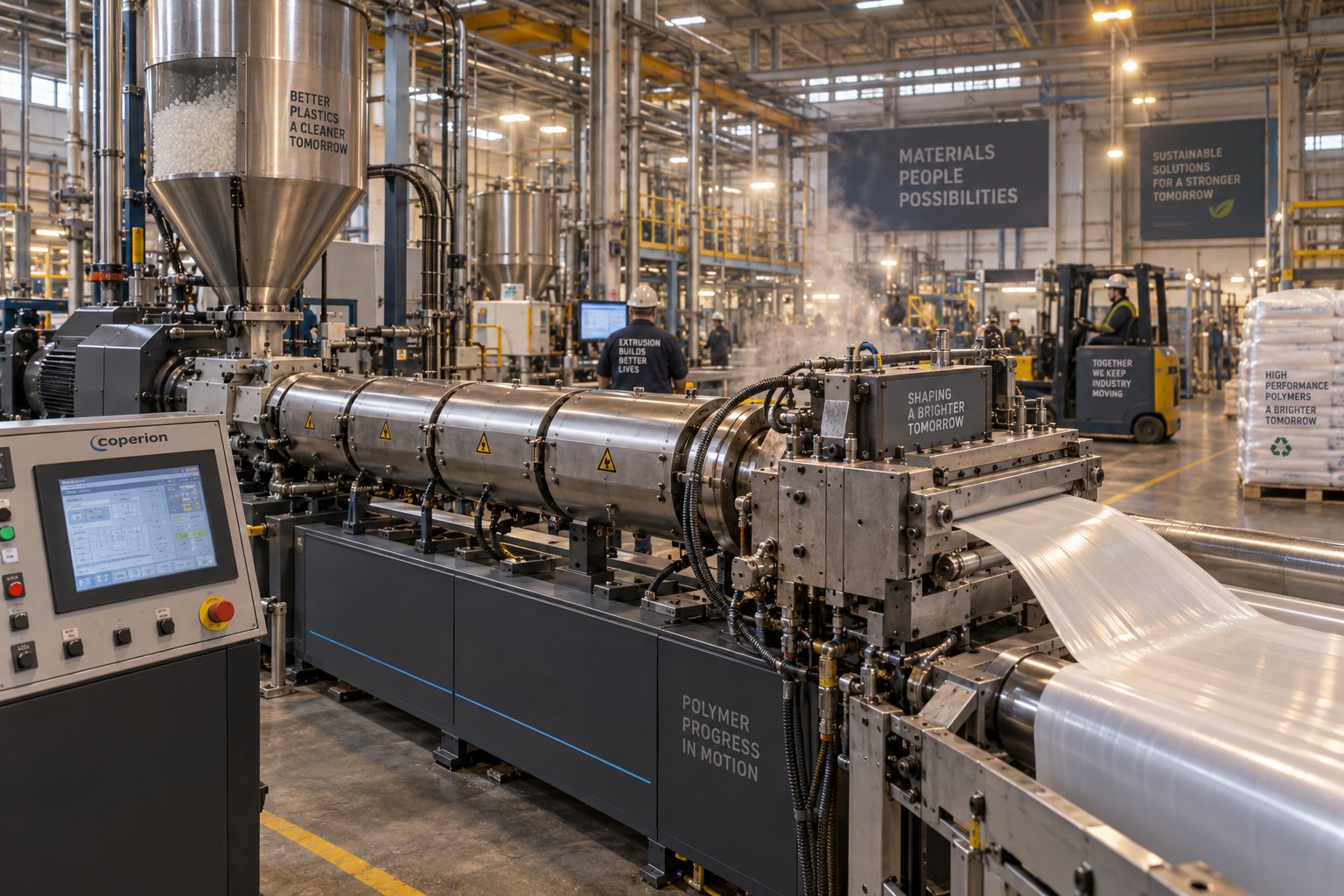
Application-Specific Screw Design Across PP Extrusion Types
A screw and barrel combination that runs beautiful PP pipe can produce terrible blown film — even if the PP grade, barrel metallurgy, and temperature profile stay exactly the same. Why? Because each extrusion application imposes a unique set of priorities on how the melt is generated, conveyed, and delivered to the die. Melt temperature uniformity, gel tolerance, output consistency, pressure stability, and venting capability all rank differently depending on what the extrudate becomes after it leaves the die lip. Treating an extruder screw barrel for PP as interchangeable across applications is one of the most common — and most expensive — specification errors processors make.
Here is how screw and barrel design priorities shift across the major PP extrusion application types:
- Blown film: Melt temperature uniformity and extremely low gel counts — gels cause bubble breaks and optical defects.
- Cast film: Tight melt temperature control for uniform chill-roll contact and consistent gauge.
- Sheet extrusion: Broad output range capability with consistent melt pressure for flat die feeding.
- Pipe extrusion: High sustained output at stable melt pressure to maintain wall thickness uniformity.
- Profile extrusion: Precise melt pressure consistency and low melt temperature to hold complex die shapes.
- Fiber and monofilament: Very tight melt temperature tolerance and zero unmelts to prevent filament breakage.
- Pelletizing and compounding: Enhanced mixing, high throughput, and often devolatilization capability.
- Recycling lines: Vented barrel capability to extract moisture and volatiles from post-consumer or post-industrial PP scrap.
Screw Design for PP Film and Sheet Extrusion
Film extrusion — whether blown or cast — places the most demanding requirements on melt quality of any PP application. Imagine stretching a thin PP film just 20 to 30 microns thick across a bubble or chill roll. At that thickness, every thermal inconsistency, every gel particle, every unmelt fragment becomes a visible defect or a potential break point. As Nordson Xaloy's engineers emphasize, the mechanical, optical, and appearance properties of film are highly sensitive to the temperature and pressure of the melt, the efficiency of colorant distribution, and the presence or absence of gels or degraded polymer — all of which are directly affected by screw design.
PP blown film screws typically incorporate barrier flight sections to prevent solids-bed breakup from sending unmelt fragments into the die. The barrier design physically separates molten PP from still-solid pellets, ensuring that only fully melted polymer reaches the metering zone. Following the barrier section, a distributive mixing element — a pineapple mixer or toothed ring design — homogenizes the melt stream without generating the excessive shear heat that PP's thermal sensitivity cannot tolerate. For high-output blown film lines, Nordson recommends either a barrier screw or a mixing element, or both, specifically because gels cause both quality defects and mechanical breakage in films.
Cast film PP screws share the same gel sensitivity but add another priority: extremely tight melt temperature uniformity. When molten PP contacts the chill roll, any temperature variation across the web width translates directly into gauge non-uniformity. Cast film lines operate at speeds that can exceed 365 meters per minute, leaving almost no downstream opportunity to compensate for melt quality problems that originated inside the extruder barrel. Screws for cast film PP applications typically feature longer metering zones than their blown film counterparts, providing additional residence in the homogenizing section to iron out thermal gradients before the melt enters the flat die.
Sheet extrusion for thermoforming operates at lower line speeds and thicker gauges, which relaxes the gel sensitivity somewhat but raises the importance of output consistency. PP sheet lines feeding a thermoformer need steady extruder barrel pressure to maintain uniform sheet thickness across wide flat dies — sometimes exceeding three meters in width. Screws designed for PP sheet typically use moderate-depth metering channels that balance high output capacity against adequate shear mixing, often paired with a gear pump downstream to dampen any residual pressure variation the screw alone cannot eliminate.
Screw Design for PP Pipe, Profile, and Fiber Lines
Pipe extrusion demands something fundamentally different from the screw than film does. Where film prioritizes melt perfection at the molecular level, pipe extrusion prioritizes sustained high output at rock-steady melt pressure. PP pipe — used extensively in plumbing, chemical transport, and drainage systems — requires wall thickness uniformity measured in hundredths of a millimeter over continuous production runs lasting days or weeks. Any output surging or pressure fluctuation from the extrusion barrels shows up as wall thickness variation that fails dimensional specifications.
Screws for PP pipe extrusion tend to feature deeper metering channels than film screws, maximizing volumetric throughput while relying on the screw's mixing section and the downstream melt pipe geometry to achieve adequate homogeneity. Barrier flight designs remain beneficial for pipe screws but are sized more aggressively — with wider solids channels — to handle the high feed rates these lines demand. The trade-off is that the deeper metering channels generate slightly less shear mixing per revolution, which is acceptable because pipe specifications tolerate a wider range of surface quality than film does.
Profile extrusion — window frames, edge trim, gaskets — flips the priority again. Profiles typically run at much lower output rates than pipe, and the complex die geometries require a melt with extremely consistent viscosity and low temperature to hold the intricate cross-sectional shape during cooling. PP profiles benefit from screws with relatively shallow metering zones that produce more intensive mixing at lower throughput, combined with conservative barrel temperature profiles that keep the melt as cool as possible while still fully homogenized. Screw speed on profile lines is often deliberately limited to prevent the shear heating that would soften the melt beyond the die's ability to maintain shape definition.
Fiber and monofilament extrusion represents perhaps the least forgiving PP application from a melt quality standpoint. A single spinneret plate may contain dozens or hundreds of tiny orifices, each producing an individual filament just a few denier in diameter. One unmelt particle or one degraded gel fragment plugs an orifice, disrupts the spinning process, and creates a broken filament that contaminates the entire fiber bundle. Screws for PP fiber lines prioritize zero-defect melting above all else — barrier flights plus fine-clearance dispersive mixers to catch the last residual unmelt, followed by very fine screen packs (sometimes 200 mesh or finer) as a final safeguard. Metering zone depths are kept shallow to maximize shear-driven homogeneity, with screw speeds carefully controlled to prevent the thermal overshoot that degrades PP's melt strength and disrupts drawdown stability at the spinneret.
Pelletizing and Recycling Line Considerations for PP
Pelletizing and compounding lines occupy a distinct category because the screw must accomplish more than simply melting and conveying. These lines blend additives, disperse fillers, incorporate colorants, and produce a pelletized feedstock that downstream processors rely on for consistency. For PP compounding, screws need robust mixing capability — often achieved through modular twin screw and barrel configurations that allow kneading blocks, toothed mixing elements, and conveying sections to be arranged in application-specific sequences.
Recycling lines add another critical requirement: devolatilization. Post-consumer and post-industrial PP scrap almost always contains moisture, residual inks, adhesives, and volatile contaminants that must be extracted before the recycled melt can be pelletized into usable feedstock. As extrusion expert Jim Frankland details, vented extruders with two-stage screws are the standard approach for processing post-consumer reclaim. The first stage melts the polymer and feeds it to a vent zone where volatiles escape — either at atmospheric pressure or under vacuum. The second stage must convey more material than the first stage produces, keeping the vent zone only partially filled so that devolatilization actually occurs instead of melt pouring out of the vent port.
Designing a two-stage screw for PP recycling is more challenging than for most other polymers. PP's low melt viscosity means the pressure-flow leakage through the second-stage channels is proportionally larger, making the balance between first-stage output and second-stage conveying capacity more sensitive to head pressure variations. Frankland emphasizes that the pressure flow is proportional to the cube of the channel depth and depends heavily on viscosity — and since PP's viscosity is already low, even small errors in second-stage channel depth sizing can upset the vent-zone balance and cause melt discharge through the vent. Recycling lines that also require tighter filtration to catch contaminants further complicate matters, because screen packs elevate head pressure and shift the first-stage versus second-stage output balance.
For processors running PP across any of these application types, the takeaway is clear: a screw and barrel specified for one application will underperform — sometimes dramatically — when repurposed for another. The dimensional parameters, mixing element selection, barrier design, venting provisions, and even the metallurgy must be tailored to the specific end use. Manufacturers like NANHAIYA, which offers custom and replacement single screw barrels configured specifically for pipe, film, sheet, pelletizing, and recycling extrusion lines, provide processors a way to source purpose-built screw and barrel sets rather than adapting a generic design that compromises across every application it touches.
Matching the screw design to the application is only half of the specification process. The other half is knowing exactly what information to provide when ordering new or replacement components — and what mistakes to avoid in the specification itself. Getting that communication right determines whether the hardware you receive actually performs in your specific PP processing environment or simply looks right on paper.
PP Screw and Barrel Specification Checklist for Processors
Imagine calling a screw manufacturer and saying, "I need a replacement screw for PP." That single sentence leaves out nearly every detail the engineering team needs to build a component that actually performs in your process. PP homopolymer for blown film and 30 percent glass-filled impact copolymer for automotive injection molding both qualify as "PP" — yet the screw geometry, barrel metallurgy, mixing elements, and surface treatments they demand are worlds apart. The quality of the specification you provide directly determines the quality of the hardware you receive. Vague requests produce generic parts. Detailed specifications produce precision components matched to your exact processing environment.
Essential Specification Data Points for PP Screw Orders
Whether you are ordering from an OEM channel, an aftermarket specialist, or a factory-direct supplier, these data points form the foundation of a correct screw barrel for injection molding or extrusion. Missing even one can lead to a component that fits the machine but fights the process.
- Polymer type and specific grade: State the exact PP resin — homopolymer, random copolymer, or impact copolymer — along with the supplier name and grade designation. Different grades carry different melt flow indices, crystallinity levels, and thermal sensitivities that directly shape plastic extrusion screw design decisions.
- Filler type and loading percentage: Specify whether the compound contains glass fiber, talc, calcium carbonate, or other reinforcements, and at what weight percentage. A 20 percent talc-filled PP and a 40 percent glass-filled PP require fundamentally different barrel liners and screw flight treatments.
- Target output rate: Provide the required throughput in kilograms per hour. This anchors the screw diameter selection and influences metering zone depth and overall channel sizing.
- Screw diameter and L/D ratio: Supply the nominal screw diameter and the existing or desired L/D ratio. If a used twin screw extruder or a single-screw machine is being re-screwed, include the machine make and model so the manufacturer can cross-reference known specifications.
- Compression ratio: Specify the current or desired compression ratio. If the worn screw has been measured, share those channel depth readings so the manufacturer can calculate the original intent and recommend adjustments if warranted.
- Mixing element requirements: Indicate whether barrier flights, Maddock mixers, pineapple mixers, or distributive elements are needed — and where along the screw they should be positioned. Reference the PP grade's mixing demands discussed throughout this article.
- Barrel metallurgy needs: State whether a nitrided, bimetallic, or specialty-lined barrel is required based on your compound's abrasion and corrosion profile.
- Temperature zone count and barrel length: Provide the number of independent heating and cooling zones on your barrel, plus the overall barrel length. This ensures any replacement barrel matches the machine's thermal control architecture.
- Application type: Specify what you are producing — blown film, cast film, sheet, pipe, profile, fiber, pelletizing, or recycling. As the previous chapter demonstrated, each application shifts the screw design priorities significantly.
- Barrel bore measurements: If ordering a replacement screw, include current barrel bore diameter readings at multiple stations along the length. A properly specified replacement screw must account for the barrel's current condition, not just its original nominal bore.
How to Communicate Your PP Processing Needs to a Manufacturer
A numbered checklist is only useful if it reaches the right people in the right format. When contacting a screw barrel manufacturer, package your specification data into a single document — a structured email, a filled-in RFQ form, or a shared spreadsheet — rather than spreading details across multiple phone calls and messages. Include photographs of the worn screw showing visible wear patterns, and attach any dimensional inspection reports from your most recent screw pull. If original OEM drawings exist, share them. If they do not, the worn screw measurements combined with the data points above give a competent manufacturer everything needed to reverse-engineer and improve upon the original design.
Explaining why you are replacing the screw matters as much as the dimensional data. Did the previous screw wear prematurely from glass-fiber abrasion? Were you experiencing surging that process adjustments could not resolve? Is the replacement an opportunity to upgrade from a general-purpose design to a barrier screw with mixing elements? Sharing the processing context — not just the numbers — allows the manufacturer's engineering team to recommend optimizations you might not have considered. Factory-direct manufacturers like NANHAIYA, which builds custom and replacement single screw barrels for pipe, film, sheet, pelletizing, recycling, and general-purpose extrusion lines, can leverage this context to configure application-specific screw and barrel sets rather than defaulting to a generic replacement.
Avoiding Common Specification Mistakes
Three specification errors account for the majority of mismatched replacements in PP processing:
- Ordering by machine model alone without verifying current barrel condition. The same machine model may have been re-barreled, modified, or fitted with a non-standard screw at some point in its history. Relying on the nameplate without measuring what is actually installed leads to components built to specifications the machine no longer matches.
- Omitting the filler type and loading. A screw specified for "PP" without mention of 25 percent glass fiber will arrive with nitrided flights instead of tungsten carbide hardfacing — and wear through in a fraction of the expected service life.
- Failing to specify the application. A screw optimized for pipe extrusion delivers high throughput at the expense of the gel-free melt quality that blown film demands. Without knowing the end use, no manufacturer can resolve that trade-off correctly on your behalf.
Every detail you provide during the ordering process is an investment in the performance of the finished component. The extruder screw barrel for PP that arrives at your loading dock should reflect your specific resin, your specific application, and the current condition of your specific barrel — not a best guess averaged across a hundred different processing scenarios. Treat the specification as the engineering document it truly is, and the hardware will repay that precision across every production hour it runs.
Frequently Asked Questions About Extruder Screw Barrels for PP
1. What L/D ratio and compression ratio work best for an extruder screw barrel for PP?
For most polypropylene grades, an L/D ratio between 24:1 and 30:1 delivers the best balance of complete melting and minimal thermal degradation. Compression ratios of 2.5:1 to 3.5:1 suit unfilled PP homopolymer and copolymer, while filled PP compounds — especially those with glass fiber — benefit from the lower end of that range to reduce filler breakage and abrasive screw wear. These parameters should always be verified against the specific resin supplier datasheet and your equipment manufacturer's guidelines.
2. Why can't I use an HDPE screw to process polypropylene?
Polypropylene has a sharper crystalline melting point, lower melt viscosity, and greater susceptibility to chain scission than HDPE. A screw designed for HDPE typically features deeper metering channels and a compression profile tuned to PE's broader softening range. Running PP through such a screw often leads to localized overheating, output surging, yellowing, and reduced melt strength because the geometry fails to match PP's narrow processing window and shear sensitivity.
3. When should I upgrade to a bimetallic barrel for PP extrusion?
A bimetallic barrel becomes necessary once filler loadings exceed roughly 15 to 20 percent by weight — regardless of whether the filler is glass fiber, talc, or calcium carbonate. Glass-fiber-filled PP at 30 to 40 percent loading is particularly aggressive, requiring tungsten-carbide-enhanced bimetallic liners to achieve economical barrel life. For unfilled PP homopolymer and copolymer, standard nitrided steel barrels typically provide adequate service with routine inspection. Manufacturers like NANHAIYA (nhyscrews.com) offer custom bimetallic single screw barrel options tailored to specific PP compound requirements.
4. What causes output surging when extruding polypropylene?
Surging in PP extrusion most commonly stems from two screw-related issues. First, feed zone inconsistency — PP pellets have low friction against steel, so any wear or overheating in the feed section causes intermittent solids conveying. Second, metering section wear increases flight-to-bore clearance, allowing low-viscosity PP melt to leak backward over the flights in cyclic pulses. Checking feed throat cooling below 60 degrees C, inspecting for hopper bridging, and performing a screw pull to measure flight clearance are the key diagnostic steps.
5. How do barrel temperature profiles differ for filled versus unfilled PP?
Filled PP compounds generally require slightly higher barrel temperatures across the compression and metering zones compared to unfilled grades. Fillers like talc, CaCO3, and glass fiber act as thermal sinks, absorbing heat that would otherwise raise the polymer temperature. Without compensating for this thermal absorption, filled compounds arrive at the die insufficiently plasticized, causing high die pressures and poor output consistency. However, glass-fiber-filled PP needs extra caution because higher barrel temperatures combined with fiber-induced shear heating can push the actual melt temperature beyond PP's degradation threshold faster than expected.
Written by
Nanhaiya Technical Team
Zhoushan Nanhaiya Plastic Machinery Co., Ltd.
The Nanhaiya technical team supports screw and barrel manufacturing projects through application review, technical communication, custom manufacturing coordination, and production and quality control.
Discuss Your Application
Related Articles
More insights on screw barrel technology and plastics processing.
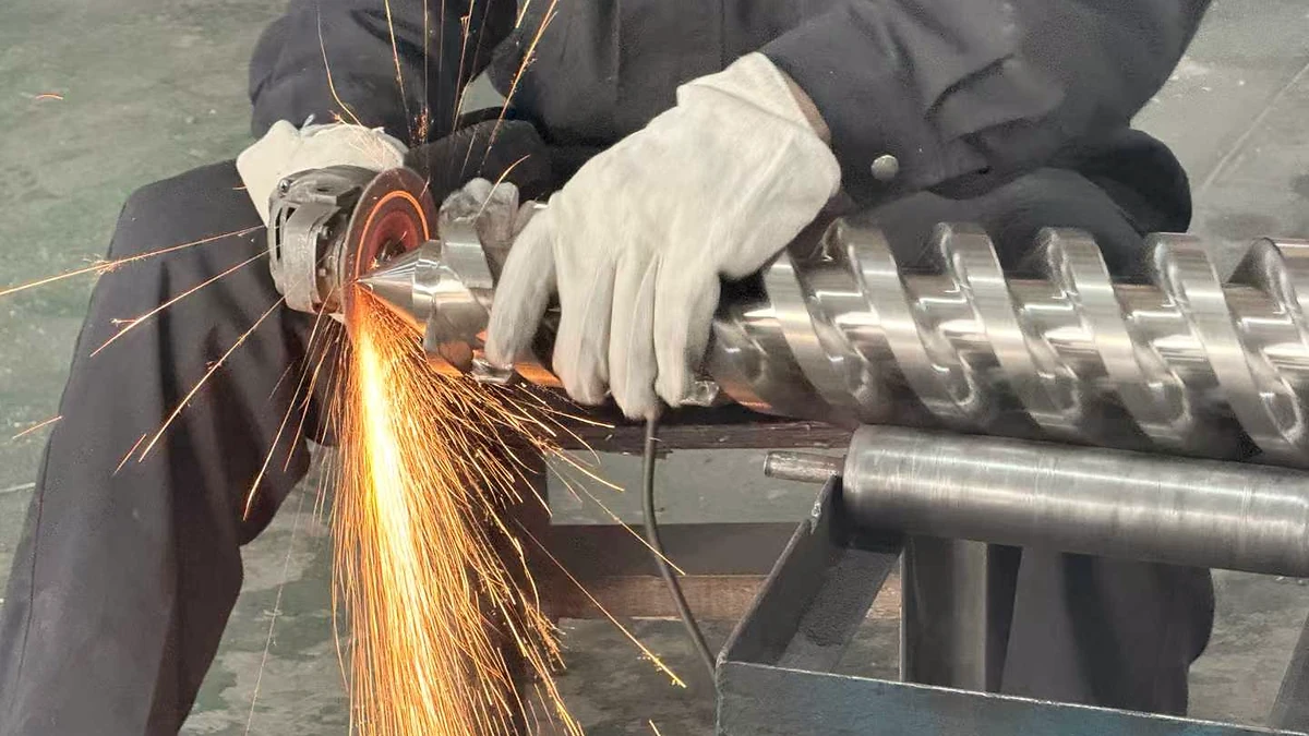
Plastic Extruder Screw Barrel Service: Match The Fix To The Wear
Oct 27, 2026
Learn how plastic extruder screw barrel service works — from zone-by-zone wear diagnosis and measurement methods to repair techniques, material matching, and maintenance scheduling.
Read Article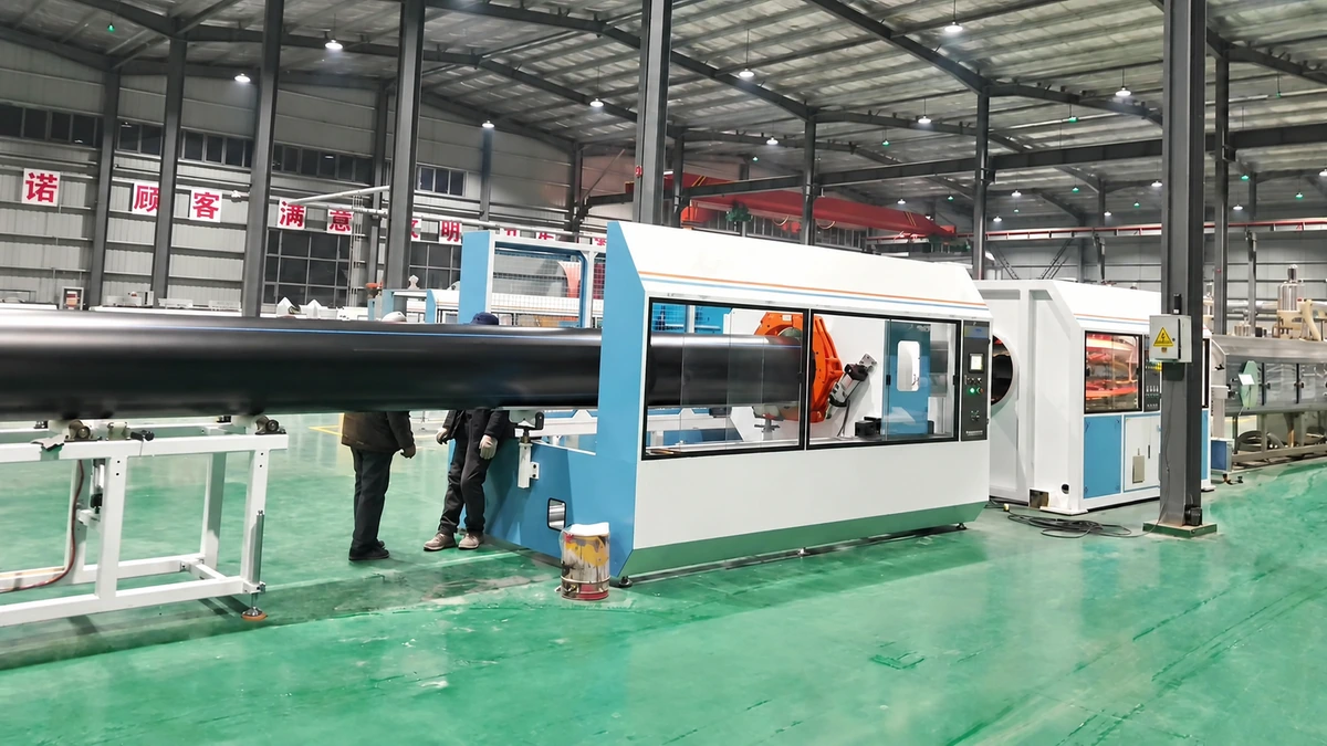
PE Pipe Extrusion Line Decoded: From Pellet to Perfect Pipe
Oct 27, 2026
Learn how a PE pipe extrusion line works — components, process steps, screw-barrel selection, vacuum calibration, automation, and a buyer's guide for smart purchasing.
Read Article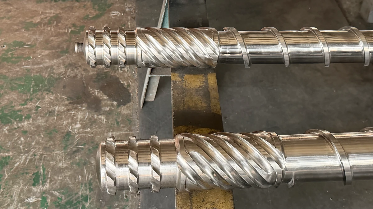
Extruder Screw Design: Match Your Polymer or Pay the Price
Oct 26, 2026
Extruder screw design guide covering geometry parameters, polymer-specific screw selection, mixing principles, wear-resistant materials, and a step-by-step design workflow.
Read ArticleLooking for something else?
Search by material, symptom or product and jump straight to the relevant page.
These are navigation suggestions based on keyword matching — not a quotation, not a delivery commitment, and not a substitute for engineering review. Final specification is confirmed by our engineers against your drawings and processed material.
Need help with screw barrel selection?
Share your machine model, processed material and application. Our team can help with pricing and technical support.