

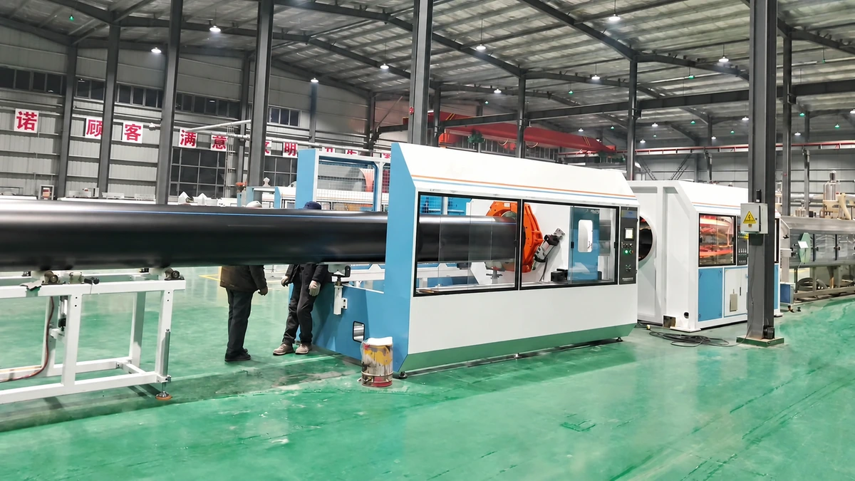
What Is a PE Pipe Extrusion Line and Why It Matters
Imagine a system that swallows tiny plastic pellets at one end and delivers perfectly round, pressure-rated pipes at the other — continuously, hour after hour, with tolerances measured in fractions of a millimeter. That is exactly what a PE pipe extrusion line does, and it is the backbone of virtually every modern plastic pipe production line serving municipal and industrial infrastructure worldwide.
Defining the PE Pipe Extrusion Line
A PE pipe extrusion line is a continuous manufacturing system that melts polyethylene resin, forces the molten polymer through an annular die to form a hollow profile, and then sizes, cools, and cuts the resulting pipe to precise diameter, wall thickness, and length specifications.
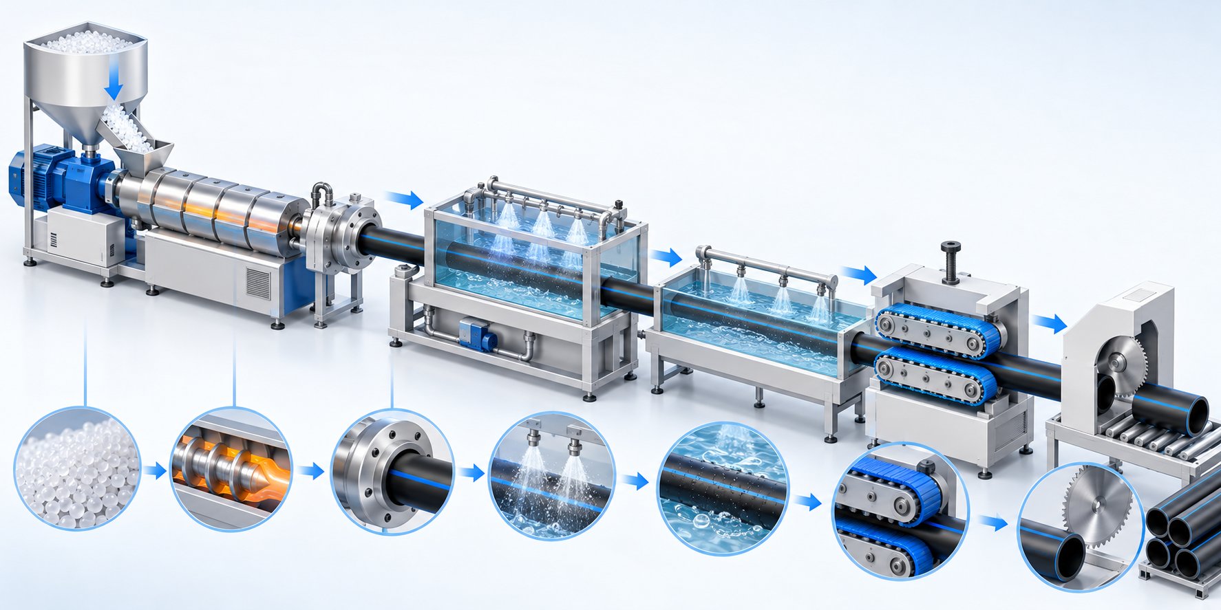
Unlike batch molding processes, this system never stops forming product during a production run. Raw polyethylene pellets enter a hopper, travel through a heated barrel where they are melted and homogenized by a rotating screw, and emerge from a die head as a soft tube. That tube is immediately drawn through a vacuum calibration tank, cooled in water baths, pulled at a controlled speed by a haul-off unit, and finally cut to length or wound into coils. Every station in the chain — material feeding, extrusion, die forming, vacuum sizing, cooling, haul-off, cutting, and stacking — must work in tight synchronization, because dimensional accuracy depends on balancing melt output, traction speed, and cooling rate simultaneously.
Why PE Pipes Dominate Infrastructure Projects
You might wonder why polyethylene earns so much attention among pipe materials. The reasons are practical and well-documented:
- Corrosion resistance — PE does not rust, rot, or suffer from electrochemical degradation, giving it a clear edge over metal alternatives in buried and marine environments.
- Flexibility — polyethylene pipes can accommodate ground movement, thermal expansion, and even seismic activity without cracking.
- Long service life — properly manufactured HDPE extrusions routinely carry design lives exceeding 50 years under rated pressure conditions.
- Fusion-weldable joints — butt fusion and electrofusion create monolithic, leak-free connections that are as strong as the pipe itself.
- Lightweight handling — PE pipes weigh significantly less than steel or ductile iron equivalents, reducing transportation and installation costs.
These advantages have made PE the material of choice for water supply, gas distribution, drainage, agricultural irrigation, and industrial fluid transport. The extrusion line, in turn, is the single piece of infrastructure that makes all of these products possible at scale.
What This Guide Covers
This article is designed as a vendor-neutral, engineering-focused resource. Whether you are a production manager optimizing an existing line or a buyer evaluating pipe extruders for a new facility, you will find practical detail on every stage of the process. Here is what to expect:
- A component-by-component breakdown of every major station in the line
- Raw material selection — PE grades, additives, and how resin choice shapes line configuration
- A step-by-step walkthrough of the extrusion process from pellet to finished pipe
- Single-screw vs. twin-screw extruder configurations and when each makes sense
- Vacuum calibration, die head design, and inline quality control techniques
- Multi-layer co-extrusion and line configuration variants
- Automation, PLC control, and how modern systems reduce scrap
- A structured buyer's guide with evaluation criteria and questions to ask manufacturers
Every section builds on the previous one, so by the end you will have a complete mental model of how polyethylene extrusion transforms raw resin into infrastructure-grade pipe. The journey starts where every pipe begins — with the equipment itself.
Core Components of a PE Pipe Extrusion Line Explained
Picture a relay race where every runner must match the exact pace of the teammate before them. Drop the baton at any handoff and the whole race is lost. A PE pipe extrusion line works the same way — it is a chain of specialized stations, and each one must be precisely matched in capacity and speed to every other. A mismatch between even two components can produce scrap, dimensional drift, or costly downtime.
Let's walk through each station from front to back so you know exactly what every piece of pipe extrusion machinery does, why it matters, and which performance parameter to watch.
Extruder and Screw-Barrel Assembly
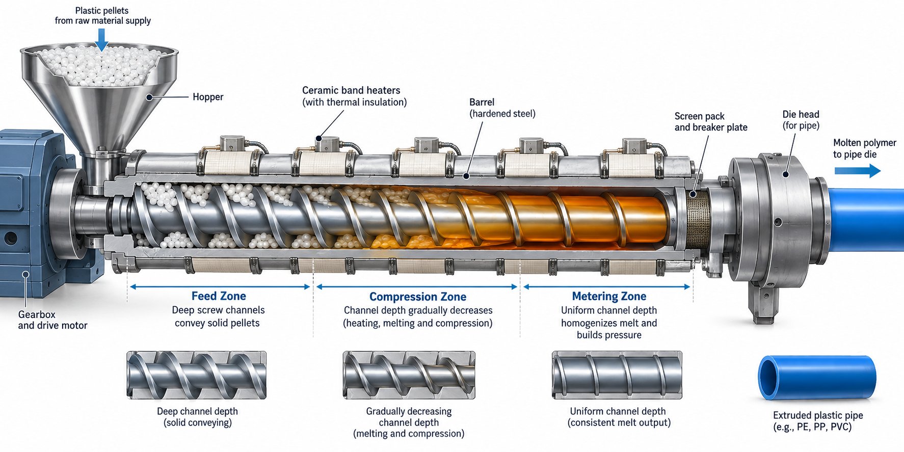
The single-screw extruder is the heart of the entire production line. It receives raw polyethylene pellets, melts them into a homogeneous mass, and delivers that melt under controlled pressure to the die head. Sounds simple, but the engineering inside the barrel is anything but.
Here is what happens along the length of the screw:
- Feed zone — pellets drop from the hopper into the barrel's first section. The screw channel is deepest here, designed to convey solid granules forward while preventing bridging.
- Compression (transition) zone — the screw channel gradually becomes shallower, compacting the pellets and generating shear heat. This mechanical energy, combined with barrel heaters arranged in individually controlled zones, melts the polyethylene.
- Metering zone — the final section of the screw delivers a fully molten, pressure-stable stream to the die. Uniform channel depth here ensures consistent output rate and melt temperature.
Surrounding the screw, the barrel features multiple heating and cooling zones — typically controlled by ceramic band heaters and air or water cooling — that allow operators to fine-tune the temperature profile along the entire length. The drive system, usually an AC servo or vector motor coupled through a high-torque gearbox, governs screw speed (RPM) and directly affects throughput.
Why does this matter for your finished pipe? Because screw and barrel geometry — the length-to-diameter (L/D) ratio, compression ratio, and barrier flight design — directly controls melt quality, energy efficiency, and maximum output. A typical L/D ratio for HDPE extrusion falls in the 30:1 to 36:1 range, providing enough residence time for thorough melting without degrading the polymer. Get the screw design wrong and you'll fight melt inconsistency, gel particles, and excessive energy consumption for the life of the machine.
Die Head, Calibration Tank, and Cooling System
Once the extruder delivers its pressurized melt, three stations work in rapid succession to shape and solidify it into a dimensionally accurate pipe.
Spiral mandrel die head. The die head distributes the annular melt stream evenly around a central mandrel. Spiral flow channels inside the die eliminate weld lines and ensure uniform wall distribution before the molten tube exits through the die gap. The die is built from high-strength alloy steel with precision-machined flow channels and independent temperature control, because even a small thermal imbalance can cause one side of the pipe wall to run thicker than the other.
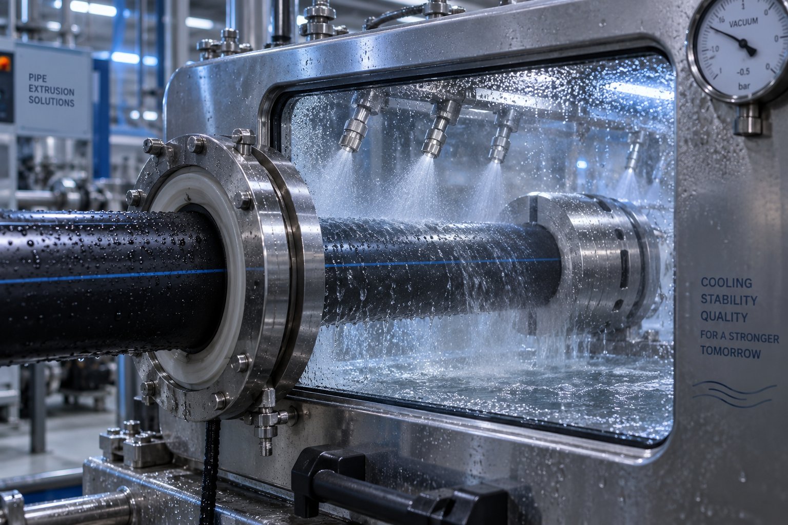
Vacuum calibration tank. Immediately after leaving the die, the soft, still-molten tube enters a stainless steel vacuum tank containing a precision-machined sizing sleeve. A controlled vacuum — commonly in the range of 0.02 to 0.06 MPa negative pressure — creates a pressure differential that pushes the pipe's outer surface firmly against the sleeve. Simultaneously, water sprays begin cooling the outer skin. This is the station that locks in the pipe's outside diameter, roundness, and surface finish. Sleeve material is typically chrome-plated brass or stainless steel, machined to tolerances within ±0.02 mm.
Spray and immersion cooling baths. The pipe exits the calibration tank with a solidified outer skin but still carries significant internal heat. Additional cooling tanks — using spray nozzles, immersion baths, or a combination — bring the pipe below its crystallization temperature so it becomes fully rigid. Cooling water temperature is typically held between 15 °C and 20 °C, and the total cooling length scales directly with pipe diameter and wall thickness. Insufficient cooling is one of the most common causes of post-production warping and ovality.
Haul-Off, Cutter, and Downstream Equipment
Everything upstream means nothing if the pipe cannot be pulled steadily, cut cleanly, and handled efficiently at the end of the line.
Haul-off unit. A caterpillar (dual-belt or multi-pad) haul-off grips the cooled pipe and pulls it through the entire downstream section at a precisely controlled speed. This is the speed reference for the whole line. The relationship between extruder output (kg/h) and haul-off speed (m/min) is the primary lever controlling wall thickness — speed the puller up, and the wall gets thinner; slow it down, and the wall gets thicker. Even small speed oscillations can create repeating thickness patterns, so servo-driven haul-offs with stable clamping pressure are essential.
Cutting unit. For large-diameter straight-length pipes, planetary saws or chip-free cutters orbit the pipe and produce clean, burr-free ends without generating plastic chips that contaminate the factory. For smaller-diameter pipes typically wound into coils, simpler guillotine or rotary cutters handle the job.
End-of-line equipment. Depending on the product, the line may include automatic stackers for straight pipes, coiling machines for flexible pipes up to approximately 110–160 mm OD, or belling machines that form a socket end directly onto the pipe for push-fit jointing.
Component Reference at a Glance
The table below summarizes every major station in a polyethylene extrusion line, its core function, and the single most important performance parameter to evaluate:
| Component | Function | Key Performance Parameter |
|---|---|---|
| Hopper and Feeding System | Delivers resin pellets and additives to the extruder at a controlled rate | Dosing accuracy (gravimetric vs. volumetric) |
| Single-Screw Extruder | Melts, homogenizes, and pressurizes polyethylene resin | Output rate (kg/h) at target melt quality |
| Spiral Mandrel Die Head | Distributes melt uniformly into an annular pipe profile | Wall thickness uniformity (eccentricity %) |
| Vacuum Calibration Tank | Sets outer diameter and surface finish via vacuum sizing sleeve | Vacuum level (negative pressure in mbar/MPa) |
| Spray/Immersion Cooling Tanks | Removes residual heat to fully solidify the pipe | Cooling water temperature and total contact length |
| Caterpillar Haul-Off | Pulls pipe at constant speed, controlling wall thickness | Speed stability and clamping force consistency |
| Cutting Unit (Saw/Cutter) | Cuts pipe to specified length with clean, chip-free ends | Length accuracy and cut-face quality |
| Stacker / Coiler / Belling Machine | Collects finished pipe for packaging or adds socket ends | Coil tension control or socket dimensional accuracy |
| PLC / HMI Control System | Coordinates all stations, monitors parameters, logs production data | Integration capability and real-time feedback speed |
Every row in that table represents a potential bottleneck. A high-output extruder paired with an undersized cooling section will force you to slow the entire line. A precision die head feeding into a haul-off with unstable speed control will produce pipes with wall thickness that drifts in and out of tolerance. The takeaway is straightforward: capacity matching across every station is not optional — it is the single biggest factor determining whether your line runs at peak efficiency or limps along generating scrap.
With the hardware mapped out, the next logical question is what you actually feed into it. The resin grade, additives, and material preparation you choose will shape not only pipe performance but also how you configure and operate every component described above.
Raw Material Selection and PE Grade Considerations
A perfectly engineered pipe production line can still produce substandard pipe if the wrong resin walks in the door. Material selection is the decision that quietly shapes everything downstream — temperature profiles, screw speeds, cooling lengths, and ultimately the mechanical performance of every meter of pipe you ship. Yet it is one of the most overlooked topics in the industry. Let's fix that.
PE Resin Grades and Their Impact on Processing
Polyethylene is not a single material. It is a family of polymers split into grades by density, molecular weight, and long-term strength classification. When you are running an hdpe extruder or configuring a new line, two parameters matter most: Melt Flow Index (MFI) and density. MFI tells you how easily the molten polymer flows — a lower value means longer molecular chains, higher melt viscosity, and stronger finished pipe. Density, measured in g/cm³, reflects how tightly those chains pack together and directly determines stiffness, tensile strength, and chemical resistance.
Here is how the most common pipe-grade polyethylenes compare side by side:
| Grade | Typical MFI Range (g/10 min) | Density Range (g/cm³) | Primary Pipe Application | Extrusion Temp Window |
|---|---|---|---|---|
| PE100 (HDPE) | 0.2 – 0.5 | 0.941 – 0.960 | High-pressure water mains, gas distribution (PN16 rated) | 190 – 230 °C |
| PE80 (HDPE / MDPE) | 0.3 – 1.0 | 0.930 – 0.955 | Medium-pressure water and gas pipelines (PN12 rated) | 180 – 220 °C |
| MDPE | 0.5 – 2.0 | 0.926 – 0.940 | Gas service lines, small-diameter water distribution | 180 – 210 °C |
| LDPE | 0.3 – 2.0 | 0.910 – 0.925 | Low-pressure irrigation, drainage, flexible conduit | 150 – 210 °C |
| PE-RT (Type I / II) | 0.5 – 1.5 | 0.930 – 0.945 | Hot-water underfloor heating, radiator connections | 190 – 230 °C |
Notice the pattern: pipe-grade resins sit at the low end of the MFI scale, typically below 1.0 g/10 min. That low flow rate corresponds to long polymer chains that resist cracking under sustained internal pressure — exactly what a 50-year-service-life water main demands. PE100, with a minimum required strength (MRS) of 10.0 MPa, can handle operating pressures up to PN16 at SDR 11, while PE80's MRS of 8.0 MPa caps it at PN12 under the same geometry. Those strength differences directly influence wall thickness design and, consequently, how much resin per meter the line must push through the die.
Additives, Masterbatch, and Material Preparation
Raw resin alone does not make a finished pipe. A range of additives must be blended in at precise concentrations before or during extrusion:
- Carbon black (2 – 3 % by weight) — the primary UV stabilizer for outdoor HDPE pipes. Per PPI TN-47, black PE pipe containing 2 to 3 percent well-dispersed carbon black is considered stabilized against UV degradation for not less than 10 years of unprotected outdoor exposure. Particle size below 25 nm and uniform dispersion are critical; poorly dispersed agglomerates can act as stress concentrators and cause premature pressure failures.
- Hindered amine light stabilizers (HALS) and UV absorbers — used in colored (non-black) PE pipes. These additives protect the polymer by neutralizing free radicals generated by photo-oxidation, extending field life for applications like blue potable water pipe or yellow gas pipe.
- Antioxidants — process stabilizers that prevent thermal degradation during the high-temperature melt phase, and long-term antioxidants that protect the pipe wall over decades of service.
- Color pigments and stripe masterbatch — used for application identification. Blue indicates potable water, yellow signals gas, purple marks reclaimed water, and so on.
How you dose these additives matters as much as what you dose. Two common approaches exist:
- Volumetric dosing — meters material by volume (screw feeder turns). It is simpler and cheaper but less accurate because bulk density varies with pellet size, temperature, and material type.
- Gravimetric dosing — measures actual weight per unit time using load cells and adjusts feeder speed in real time. This approach delivers tighter additive control, typically within ±0.5 % of the target ratio, making it the preferred standard on any serious pipe production line.
What about drying? Most virgin HDPE pipe grades absorb very little moisture and can be processed straight from the bag. Recycled polyethylene is a different story — regrind and repelletized material can carry significantly higher moisture content and should be pre-dried in a hot-air or desiccant dryer before it enters the hopper. Skipping this step with wet recycled feedstock leads to porosity, surface blemishes, and weakened pipe walls.
How Material Choice Shapes Line Configuration
Here is where resin selection circles back to every piece of equipment described in the previous chapter. The grade you run does not just affect pipe performance — it dictates how you set up and operate the entire extrusion line.
- Screw geometry and compression ratio. Low-MFI PE100 resins, with their high melt viscosity, demand screws designed for aggressive melting — typically a higher compression ratio and barrier flight designs that maximize shear without degrading the polymer. Switch to a higher-MFI MDPE or LDPE, and that same aggressive screw may overshear the material, causing thermal degradation and gel formation. Many operators running multiple PE grades on the same hdpe extruder keep dedicated screw configurations optimized for each family.
- Temperature profile. LDPE processes comfortably at barrel temperatures as low as 150 °C, while PE100 and PE-RT often require zones set above 210 °C. PE-RT used in heating-pipe applications is especially sensitive — even small temperature excursions can shift the polymer's molecular architecture and compromise its elevated-temperature pressure rating. Tighter PID control zones and faster-response heaters pay for themselves quickly on these grades.
- Cooling requirements. Higher-density resins crystallize more slowly and need longer cooling sections to reach dimensional stability. A line configured for 250 mm PE100 pressure pipe may need twice the cooling tank length of a line producing the same diameter in LDPE irrigation pipe. Underestimating this relationship is one of the most common errors when a plastic energy pipe making line supplier is specifying new downstream equipment.
- Line speed potential. Higher-MFI resins flow more easily and can tolerate faster haul-off speeds — but only if the cooling section can keep pace. The practical maximum line speed is almost always set by the weakest link in the cooling chain, not by the extruder's output capacity.
The takeaway is simple but often ignored: choosing a PE grade is not just a materials engineering decision. It is a line configuration decision. Every parameter — from screw design to cooling length to control system sensitivity — must be matched to the resin you intend to process. Get this alignment right, and the entire system hums. Get it wrong, and you spend your days chasing dimensional problems that no amount of downstream adjustment can fully fix.
With raw materials and their processing demands clearly mapped, the logical next step is tracing exactly how those pellets transform into finished pipe — stage by stage, from hopper to final cut.
The PE Pipe Extrusion Process From Pellet to Finished Pipe
Understanding how HDPE is manufactured at the process level — not just the equipment level — is what separates a competent operator from someone simply pressing buttons on an HMI screen. Every stage in the pipe extrusion process directly controls a specific property of the finished product: strength, dimensional accuracy, surface quality, or service life. Miss a detail in any one stage and the defect compounds downstream, often becoming visible only after the pipe has already been cut and stacked.
Here is the complete sequence, broken down into the three major phases that every PE pipe extrusion machine follows from raw pellet to finished product:
- Feeding, melting, and metering
- Die forming and vacuum calibration
- Cooling, haul-off, and cutting
Let's trace a single resin pellet through the entire journey.
Feeding, Melting, and Metering
Everything begins at the hopper. Polyethylene pellets — along with any pre-dosed masterbatch and additives — enter the barrel through a gravity-fed or forced-feed throat. On a well-configured plastic pipe production line, gravimetric dosing systems continuously weigh the material stream entering the extruder, ensuring that the resin-to-additive ratio stays locked within ±0.5 % of the target recipe. Even a slight drift in carbon black concentration, for instance, can push a pipe out of UV protection compliance.
Once inside the barrel, the rotating screw takes over. The pellets progress through three functionally distinct zones:
- Solid conveying zone — pellets ride along the deep screw channel, pushed forward by friction between the barrel wall and the resin. Barrel temperature here is deliberately kept moderate to prevent premature melting, which would reduce conveying efficiency and destabilize output.
- Compression (melting) zone — as the screw channel depth decreases, pellets are compacted and subjected to intense shear. This mechanical friction generates the bulk of the thermal energy needed to melt the polymer — typically around 60 to 80 percent of total heat input comes from shear rather than barrel heaters. Barrel heaters supplement the process and fine-tune the temperature profile, but the screw does the heavy lifting. For PE100 resins, melt temperatures typically reach 190 to 230 degrees Celsius, depending on the specific grade and line configuration.
- Metering zone — the fully molten polymer flows through a constant-depth channel that builds and stabilizes pressure before the melt enters the die head. Uniform output from this zone is critical. Pressure fluctuations here translate directly into wall thickness variations in the finished pipe.
Two parameters deserve special attention in this phase: back pressure and melt homogeneity. Back pressure — the resistance the melt encounters before entering the die — needs to be high enough to ensure complete melting and thorough mixing, but not so high that it causes excessive residence time and thermal degradation. Melt homogeneity, meaning the absence of unmelted particles, temperature gradients, or poorly dispersed additives, is what ultimately determines whether the pipe wall will have uniform strength from inner surface to outer surface. A well-designed screw with an appropriate compression ratio and barrier flight geometry achieves both goals simultaneously.
Die Forming and Vacuum Calibration
The pressurized melt exits the barrel and enters the die head, where the pipe extrusion process shifts from melting to shaping. Inside the spiral mandrel die, flow channels distribute the melt evenly around a central core. The molten polymer spirals outward and converges into a continuous annular tube before passing through the die gap — the adjustable opening that defines the pipe's initial geometry.
At this point, the extrudate is soft, hot, and dimensionally unstable. Gravity alone would deform it within seconds. That is where vacuum calibration takes over — arguably the most precision-critical stage on the entire line.
Here is what happens in the calibration tank, step by step:
- The soft tube slides over a precision-machined sizing sleeve, typically chrome-plated brass or stainless steel, with internal tolerances within ±0.02 mm.
- A controlled vacuum inside the tank — generally in the range of negative 0.02 to 0.06 MPa — creates a pressure differential. Atmospheric pressure inside the pipe pushes the outer wall firmly against the sleeve surface.
- Simultaneously, water spray manifolds direct cooling water at 15 to 20 degrees Celsius onto the pipe surface, beginning the solidification of the outer skin while the interior remains molten.
The vacuum level and cooling water temperature are not arbitrary settings — they are the two variables that directly determine dimensional accuracy and surface quality. Too little vacuum and the pipe pulls away from the sleeve, producing an undersized outer diameter. Too much vacuum and the outer wall is forced outward too aggressively, potentially creating internal surface voids. Water that is too cold induces thermal shock, locking in residual stresses that cause brittleness; water that is too warm leaves the pipe soft enough to deform under downstream pulling forces.
This is also where the pipe's outside diameter is permanently set. Contrary to what many newcomers assume, it is not the die that determines the final OD — it is the calibration sleeve. The die produces an oversized tube, and the vacuum sizing tank locks it to the target dimension.
Cooling, Haul-Off, and Cutting
The pipe leaves the calibration tank with a solid outer skin but still carries substantial heat in its core. Spray cooling tanks or full-immersion baths take over, progressively extracting thermal energy until the pipe drops below its crystallization temperature and becomes fully rigid throughout its cross-section. The number and length of cooling tanks scale directly with pipe diameter and wall thickness — a 630 mm SDR 11 PE100 pipe requires dramatically more cooling capacity than a 32 mm irrigation tube.
Pulling the pipe through all of this is the haul-off unit — a caterpillar or belt-type puller that grips the cooled pipe and maintains a constant, servo-controlled pull speed. This is where wall thickness control really lives.
The ratio of extruder output (kg/h) to haul-off speed (m/min) is the single most important parameter controlling wall thickness in any PE pipe extrusion line. Increase haul-off speed while output remains constant and the wall gets thinner. Decrease it and the wall gets thicker.
This relationship is deceptively simple, but its practical implications are enormous. Even minor speed fluctuations — a belt slipping slightly, a servo drive hunting around its setpoint — produce measurable wall thickness variation in the finished product. As extrusion engineers emphasize, when haul-off speed increases while output stays the same, the product is stretched and both wall thickness and meter weight fall. Conversely, if output rises or haul-off speed drops, excess material packs into each meter, causing wall thickening, sagging, or dimensional instability before the pipe fully cools.
The final station is the cutter. For large-diameter straight-length pipe, a planetary saw or chip-free cutter travels with the pipe, making a clean, square cut without stopping the line. For smaller-diameter products destined for coils, rotary cutters handle the job before the pipe is wound onto automatic coiling machines. In both cases, cut length accuracy depends on the cutter's synchronization with haul-off speed — yet another relationship where precise coordination across stations determines final product quality.
The Complete Pipe Extrusion Process at a Glance
For quick reference, here is the entire sequence in order:
- Gravimetric feeding — resin and masterbatch are weighed and dosed into the extruder hopper at a controlled ratio.
- Solid conveying — the screw transports pellets forward through friction against the barrel wall.
- Melting and compression — shear heat and barrel heaters convert solid pellets into a uniform melt.
- Metering — the melt is pressure-stabilized and delivered to the die head at a constant flow rate.
- Die forming — a spiral mandrel die shapes the melt into a continuous annular tube.
- Vacuum calibration — controlled vacuum pulls the soft tube against a sizing sleeve, locking the outside diameter.
- Spray and immersion cooling — water baths extract heat until the pipe is fully solid throughout its wall.
- Haul-off — a servo-controlled puller maintains constant line speed and directly governs wall thickness.
- Cutting to length — a travelling saw or rotary cutter produces clean, accurate cuts without stopping the line.
- Stacking or coiling — finished pipes are collected, packaged, or wound for shipment.
Every one of these steps is interdependent. A feeding inconsistency in step one propagates as a wall thickness variation visible only at step eight. A vacuum fluctuation in step six shows up as an OD deviation at the measurement station downstream. This is why experienced operators think of the line as a single continuous system rather than a collection of independent machines — and why the choice between single-screw and twin-screw extruder configurations, covered next, carries implications far beyond the barrel itself.
Single-Screw vs Twin-Screw Extruders for PE Pipe Lines
The extruder you bolt to the front of your line is the decision that locks in your capital cost, energy bill, maintenance burden, and polymer flexibility for the next decade or more. Yet the single-screw versus twin-screw question is rarely discussed with the specificity that PE pipe producers actually need. Most buyers hear a blanket recommendation from whoever is selling them a line. The reality is more nuanced — and the right choice depends almost entirely on what you are extruding, at what volume, and with what raw material quality.
When Single-Screw Extruders Are the Right Choice
For polyethylene pipe production — whether HDPE, MDPE, or PE-RT — the single-screw extruder is the dominant configuration worldwide, and for good reason. PE resins have a wide processing window, typically tolerating a melt temperature range of 50 to 80 degrees Celsius without quality issues. That forgiving rheology means the simpler drag-flow conveying mechanism of a single screw handles the melting, homogenizing, and pressurizing job efficiently without the mechanical complexity of twin-screw designs.
Here is what makes the single-screw pipe extruder machine the default for PE lines:
- Lower capital cost — one screw, one drive, one barrel temperature profile. A single-screw extruder typically costs one-half to one-third the price of a comparable twin-screw unit of the same diameter.
- Simpler maintenance — fewer moving parts, a less complex gearbox, and a smaller spare parts inventory translate directly into less downtime and lower annual maintenance spend.
- Better energy efficiency for polyolefins — single-screw extruders processing PE pipe typically consume 0.18 to 0.22 kWh per kilogram of output. Twin-screw designs, even when processing the same polymer, generally run higher due to additional drive power and more intensive shear.
- Proven reliability — decades of field history across thousands of HDPE plant installations confirm that single-screw machines deliver stable, repeatable output for PE pipe diameters ranging from 20 mm to 800 mm and beyond.
The critical variable that separates an average single-screw line from an exceptional one is not the motor, the gearbox, or the control system. It is the screw and barrel assembly itself. Optimized screw geometry — the right L/D ratio (typically 30:1 to 33:1 for PE pipe), appropriate compression ratio, and well-designed barrier flights — directly determines how uniformly the melt is plasticized and how efficiently energy converts into throughput. Equally important is barrel metallurgy. Wear-resistant bimetallic barrels, featuring a hard alloy lining typically 1 to 2 mm thick on the bore surface, resist the abrasive and corrosive forces that gradually erode standard nitrided barrels, especially when processing pigmented compounds or resin blended with recycled content.
When Twin-Screw Configurations Make Sense
Twin-screw extruders — particularly counter-rotating parallel designs — dominate PVC pipe production because PVC is thermally sensitive and degrades quickly under the longer residence times typical of single-screw processing. The twin screw's intermeshing flights create positive mechanical conveying that pushes material forward without relying on drag flow, keeping residence times to 30 to 90 seconds versus 90 to 180 seconds for a single screw under comparable conditions.
Beyond PVC, twin-screw extruders earn their premium in several other scenarios relevant to pipe producers:
- High filler loads — calcium carbonate-filled compounds or wood-plastic composites benefit from the twin screw's positive conveying action, which prevents filler "rat-holing" through the feed zone.
- Heavily recycled material — post-consumer or post-industrial regrind with inconsistent bulk density and potential contaminants is more reliably processed by the superior mixing capability of intermeshing screws.
- Specialty compounds — CPVC, PVC-O oriented pipe, and certain engineering-polymer pipe applications where narrow thermal windows demand tighter melt temperature uniformity (typically ±1 degree Celsius for twin-screw versus ±3 degrees for single-screw).
The trade-off is straightforward: twin-screw machines cost two to three times more to purchase, carry higher maintenance complexity due to dual screws, more sophisticated gearboxes, and tighter alignment requirements, and consume more energy per kilogram when processing polyolefins. For an HDPE-only producer running below 400 kg/h, that premium is rarely recoverable through throughput or quality gains.
How Screw-Barrel Quality Affects Pipe Output
Regardless of which configuration you choose, every extruder eventually confronts the same reality: the screw and barrel wear. And when they do, the consequences cascade through every meter of pipe you produce.
Imagine the radial clearance between screw flight and barrel wall gradually widening from its original tolerance. As that gap grows, leakage flow increases — molten polymer slips backward over the flights instead of being pushed forward. The operator sees throughput dropping and compensates by increasing screw RPM. Higher RPM means more shear, which raises melt temperature. Higher melt temperature degrades physical properties in the finished pipe. Energy consumption climbs. And the dimensional stability of the pipe suffers because the output rate is no longer steady.
The wear pattern is predictable: the majority of wear occurs in high-pressure areas — the transition section and the final few turns of metering — where friction is highest. Barrier flights and mixing sections also degrade over time, losing their ability to separate the melt pool from the solid bed and to disperse additives uniformly. The result is an extruder that consumes more power to produce less pipe, with wider tolerance bands and higher scrap rates.
A common rule of thumb considers flight clearance four times the original tolerance to be the replacement threshold, but viscosity plays a role too. Higher-viscosity PE resins mask the effect of moderate wear better than lower-viscosity materials, so an extruder that seems fine on PE100 may produce noticeably degraded output when switched to a higher-MFI MDPE grade.
Proactive maintenance planning — pulling the screw periodically for measurement, recording baseline data, and sourcing quality replacement components before performance degrades — avoids the costly scenario of discovering a severely worn screw only after scrap rates spike. Experienced screw manufacturers can rebuild a worn screw multiple times to like-new tolerances, and specialists like NANHAIYA offer custom-engineered single screw barrels designed specifically for pipe extrusion applications, with bimetallic alloy linings and screw geometries matched to the PE grades and output demands of a given line. For operators seeking to restore or upgrade performance on an aging pe pipe extrusion line, a precision replacement barrel paired with an optimized screw can deliver measurable gains in throughput, energy efficiency, and dimensional consistency — often at a fraction of the cost of replacing the entire extruder.
Single-Screw vs Twin-Screw: Side-by-Side Comparison
The table below puts the key decision factors in one place. If you are configuring a new PE pipe line or evaluating whether to upgrade an existing extruder, these are the parameters that matter most:
| Evaluation Factor | Single-Screw Extruder | Twin-Screw Extruder |
|---|---|---|
| Capital Cost | Lower (roughly 1/2 to 1/3 of twin-screw) | Higher (2 to 3x single-screw of same diameter) |
| Maintenance Complexity | Lower — single screw, simpler gearbox, smaller spares inventory | Higher — dual screws, complex gearbox, tighter alignment tolerances |
| Mixing Capability | Good for polyolefins; adequate for well-formulated PE compounds | Excellent — superior for high filler loads, recycled feedstock, and PVC |
| Energy Efficiency (PE pipe) | 0.18 – 0.22 kWh/kg | 0.22 – 0.30 kWh/kg |
| Melt Temperature Uniformity | ±3 °C typical | ±1 °C typical |
| Throughput per Screw Diameter | Baseline | 20 – 40 % higher at same RPM |
| Best PE Pipe Applications | HDPE water/gas, MDPE service lines, PE-RT heating pipe, standard production | PVC/CPVC pipe, high-filler compounds, heavily recycled feedstock, PVC-O oriented pipe |
The pattern is clear: for the vast majority of polyethylene pipe production, the single-screw extruder delivers the best return on investment. Twin-screw machines earn their place on lines processing PVC, CPVC, or specialty compounds where the single screw's drag-flow mechanism cannot provide the thermal uniformity or positive conveying the material demands.
Whichever configuration sits at the front of your line, the pipe it produces is only as good as the dimensional control achieved at the next station — the vacuum calibration tank and die head. That is where tolerances are won or lost, and where the engineering gets truly precise.
Vacuum Calibration, Die Design, and Quality Control in PE Extrusion Lines
Tolerances on a finished PE pipe are measured in fractions of a millimeter. Yet between the moment molten polymer exits the die and the moment the pipe reaches the haul-off, that soft, hot tube is at the mercy of vacuum pressure, water temperature, sleeve geometry, and die gap uniformity. This is where pipe quality is truly decided — not at the extruder, and not at the cutter. If you want to understand why one hdpe pipe extrusion line consistently ships product within spec while another fights scrap every shift, look here first.
Vacuum Calibration and Sizing Principles
Imagine pushing a soft rubber balloon outward against the inside of a rigid cylinder. That is essentially what happens in a vacuum calibration tank — except the "balloon" is a continuously moving tube of molten polyethylene and the "cylinder" is a precision-machined metal sleeve.
Here is the sequence in detail. The freshly extruded tube, still soft and dimensionally unstable, enters the front of the calibration tank and slides over a sizing sleeve. A vacuum pump draws air from the sealed tank, creating a negative pressure environment — typically in the range of negative 0.02 to 0.05 MPa (roughly negative 200 to 500 mbar). Because the pipe's interior remains at atmospheric pressure, the differential forces the outer wall outward against the sleeve's inner surface. Simultaneously, water sprays or a thin film of cooling water on the sleeve surface begins extracting heat from the outer skin, hardening it in place.
Three variables control the outcome at this station:
- Vacuum level — too low and the pipe fails to seat fully against the sleeve, resulting in undersized OD and poor surface finish. Too high and the outer wall is forced outward so aggressively that internal voids or micro-cracks can form near the inner surface, weakening the pipe under long-term pressure.
- Cooling water temperature — water between 15 and 20 degrees Celsius provides controlled solidification. Colder water induces thermal shock that locks in residual stress, while warmer water leaves the outer skin too soft to hold its shape against downstream pulling forces.
- Sleeve material and length — the sleeve must combine excellent thermal conductivity with wear resistance. Wear-resistant copper alloy — specifically tin bronze (ZQSn 6-6-3) — is widely used because it transfers heat rapidly while resisting the abrasion of a continuously moving polymer surface. Stainless steel and chrome-plated brass are common alternatives, each trading off conductivity for durability or cost. Sleeve length typically ranges from 160 to 600 mm, increasing with pipe diameter to ensure the outer wall hardens sufficiently before the pipe exits the tank. If the sleeve is too short, the pipe cannot support its own weight and deforms under traction; if it is too long, friction resistance climbs, traction power demands increase, and surface finish can actually degrade.
One point that surprises many newcomers to PE pipe production: the calibration sleeve — not the die — sets the pipe's final outside diameter. The die intentionally produces a slightly oversized tube, and the vacuum tank shrinks it to the target OD. This is why sleeve machining tolerances are held to ±0.02 mm or tighter on a serious pe extrusion line. Any imperfection in the sleeve's bore transfers directly to the pipe surface.
Die Head Design for Uniform Wall Distribution
A perfectly calibrated vacuum tank cannot rescue a pipe that exits the die with uneven wall thickness. If one side of the annular melt stream is 10 percent thicker than the opposite side, that eccentricity will persist through calibration, cooling, and haul-off — resulting in a pipe that fails pressure testing because its thinnest point cannot sustain the rated stress.
This is why spiral mandrel die design matters so much. Inside the die head, the melt stream from the extruder is split and distributed around a central mandrel through a series of overlapping spiral channels. Each channel gradually reduces in depth while the adjacent channel increases, forcing the polymer to merge layer by layer into a seamless annular flow. The spiral geometry eliminates the weld lines that older "spider leg" die designs produce — lines of structural weakness where separated melt streams rejoin imperfectly.
Several design and operational factors influence wall distribution from the die:
- Die gap adjustment — most modern die heads feature adjustable centering bolts (typically four to eight, spaced around the circumference) that allow operators to shift the mandrel position relative to the outer die ring. This fine-tunes the annular gap and corrects minor eccentricity. Even on a new die, thermal expansion during warmup can shift alignment, so operators routinely check and re-center after reaching stable operating temperature.
- Flow channel geometry — the number of spiral starts, the overlap ratio, and the channel depth profile determine how uniformly the melt distributes. Poorly designed channels create dead spots where polymer stagnates, degrades thermally, and eventually breaks free as dark specks or gels embedded in the pipe wall.
- Die temperature control — independent heater zones on the die body compensate for heat losses at flanges and exposed surfaces. A temperature differential of just 5 degrees Celsius across the die face can cause measurable wall thickness variation because the melt viscosity changes with temperature. Lower viscosity on the hotter side allows more material to flow through that section, producing a thicker wall opposite the thin side.
As extrusion technology specialists note, a good fit between the extruder, die, and formulation is the best guarantee for higher output rates, lower reject, and improved reproducibility. The die design must match the extruder's melt quality and the material's rheological properties — a mismatch produces inconsistent wall thickness and poor weld quality regardless of how precisely the downstream equipment is configured.
Inline Quality Monitoring and Testing Standards
Even with perfect die geometry and optimized calibration, no extrusion pipe machine runs in a perfectly steady state. Resin lot variations, ambient temperature shifts, gradual screw wear, and minor process disturbances continuously push dimensions away from their targets. The question is not whether drift will occur, but how quickly the system detects and corrects it.
Modern hdpe extrusion lines integrate multiple inline measurement technologies that feed real-time data back to the control system:
- Laser diameter gauges — positioned after the cooling section, these non-contact sensors project measurement beams across the pipe and calculate outside diameter from the resulting shadow. Multi-axis systems (dual or triple axis) provide stronger average-diameter and estimated-ovality confidence compared to single-axis units, which can miss an oval condition oriented between their measurement planes.
- Ultrasonic wall thickness sensors — these transducers send sound pulses through the pipe wall and measure the transit time between reflected interfaces. When paired with laser OD data, the system calculates wall thickness, concentricity, minimum wall, and derived inside diameter across multiple points around the circumference. This is critical because, as measurement specialists emphasize, outside diameter alone does not prove wall thickness or concentricity — a pipe can hold OD while its lumen shifts off center.
- Ovality monitoring — derived from multi-axis diameter data, ovality is expressed as the difference between maximum and minimum diameter readings. Specifications typically define acceptable ovality using a percentage formula: (Dmax - Dmin) / Daverage × 100.
- Automated wall thickness control — in closed-loop systems, ultrasonic gauge data feeds directly to the PLC, which adjusts haul-off speed or extruder output in real time to bring wall thickness back to target. This eliminates the slow, reactive corrections that human operators make and dramatically reduces the length of out-of-spec pipe produced during a disturbance.
All of this inline monitoring exists within a framework of international standards that define what "acceptable" means. The most relevant for PE pipe producers include:
- ISO 4427 — specifies requirements for PE pipes for water supply, including dimensional tolerances for outside diameter (typically ±0.1 mm to ±1.0 mm depending on nominal size) and minimum wall thickness.
- ISO 4437 — covers PE pipes for gas supply, with similar dimensional requirements and additional testing for slow crack growth resistance and rapid crack propagation.
- ASTM D3035 — defines PE pipe dimensions based on standard dimension ratios (SDR), providing the framework for specifying wall thickness as a function of OD.
- ASTM D2122 — describes the standard test methods for determining diameter, wall thickness, out-of-roundness, length, and straightness of thermoplastic pipe.
Key quality parameters monitored during production — and their typical acceptable ranges — include:
- Outside diameter — within the tolerance band specified by ISO 4427 or the applicable product standard for the nominal size being produced
- Minimum wall thickness — must not fall below the design minimum at any point around the circumference; typically no individual reading below 95 percent of the nominal wall value
- Ovality (out-of-roundness) — generally limited to 1.5 percent of nominal OD for pressure pipe applications, though standards allow wider tolerances for coiled pipe
- Eccentricity — the difference between maximum and minimum wall thickness, divided by the sum of the two, expressed as a percentage; typically held below 10 to 12 percent for pressure-rated pipe
- Surface quality — visually and instrumentally assessed for scoring, pitting, discoloration, and embedded contaminants that could act as stress concentrators under pressure
The takeaway for anyone configuring or operating an hdpe pipe extrusion line is clear: calibration, die design, and inline measurement are not three separate topics. They form a tightly coupled system. A perfectly machined calibration sleeve cannot compensate for a poorly centered die, and a state-of-the-art ultrasonic scanner is useless if nobody closes the loop between what it measures and what the control system does about it. When all three elements work together — precise die geometry feeding a well-tuned vacuum tank, monitored by sensors that drive automatic correction — the line produces pipe that meets specification meter after meter, shift after shift.
Dimensional precision on a single-layer pipe is demanding enough. Multiply those challenges by two or three distinct polymer layers, each with its own rheology and cooling behavior, and you begin to appreciate why multi-layer co-extrusion lines represent the next level of engineering complexity.
Multi-Layer Co-Extrusion and PE Pipe Production Line Variants
A standard single-layer PE pipe handles the vast majority of water, gas, and drainage applications around the world. So why would anyone invest in the added complexity of multiple extruders, a co-extrusion die head, and a more sophisticated control architecture? The answer comes down to one word: functionality. When a single polymer layer cannot deliver everything the application demands — whether that is an oxygen barrier, a recycled-material core, a color-coded skin, or a metallic reinforcement — the production line must evolve to match.
This is where line configuration choices become strategic decisions. The diameter range you target, the number of layers you need, the way you handle finished pipe at the end of the line — each of these variables reshapes the equipment list, the floor plan, and the capital budget. Let's break down the options.
Single-Layer vs Multi-Layer Co-Extrusion Lines
A single-layer line is straightforward: one extruder feeds one die head, producing a homogeneous pipe wall from a single PE compound. This configuration covers the lion's share of extruded pipe manufacturing — HDPE pressure pipe for water and gas, MDPE service lines, irrigation tubing, and industrial drainage. It is simpler to operate, easier to maintain, and less expensive to purchase.
Multi-layer lines, by contrast, use two or three extruders — sometimes more — each feeding a separate melt stream into a co-extrusion die head. Inside that die, the streams merge into concentric layers before exiting as a single composite tube. Each layer can carry a different resin, a different color, or a different functional additive, and the result is a pipe that no single material could produce on its own.
Where does this added complexity pay off? Consider these real-world applications:
- Recycled-core pipes — a three-layer design places recycled PE in the thick middle layer (often 60 to 80 percent of the total wall) sandwiched between thin virgin-material skins. The outer layer provides UV resistance and surface quality; the inner layer ensures food-contact compliance for potable water. This approach dramatically reduces virgin resin consumption while meeting the same pressure ratings and dimensional standards as a fully virgin pipe.
- PE-RT heating pipes with oxygen barrier — underfloor heating systems require pipes that block oxygen diffusion to prevent corrosion of metal components in the circuit. A five-layer PE-RT pipe might include inner and outer PE-RT layers, adhesive tie layers, and a central EVOH (ethylene vinyl alcohol) barrier layer with an oxygen permeability low enough to satisfy DIN 4726 requirements. Each layer demands its own extruder, its own temperature profile, and precise thickness control.
- PE-Al-PE composite pipes — these combine polyethylene inner and outer layers with a thin, longitudinally welded aluminum strip in between. The aluminum provides a full oxygen barrier plus shape-retaining memory, while the PE layers deliver corrosion resistance and fusion-weldability. Production requires not only co-extrusion capability but also an inline aluminum forming and welding station — a significantly more complex pe pipe production line.
- Stripe-identified pipes — some standards require co-extruded color stripes (blue for water, yellow for gas) rather than printed markings. A small secondary extruder feeds pigmented resin through dedicated stripe channels in the die head, producing permanent identification that cannot wear off in service.
The additional equipment required for multi-layer production is substantial. Beyond the extra extruders (each with its own drive, barrel temperature control, and feeding system), you need a co-extrusion die head engineered with separate spiral distributor sections for each layer. The control system grows more complex as well — layer thickness ratios must remain constant even as overall line speed changes, which means each extruder's output must be slaved to the master line speed through coordinated servo control. Startup and grade-change procedures take longer, and troubleshooting a wall-thickness issue requires isolating which layer is drifting before making corrections.
Is it worth it? For producers targeting premium markets — municipal potable water systems that reward recycled content, European heating installations that mandate oxygen barriers, or branded pipe systems that rely on co-extruded identification — the answer is clearly yes. For a manufacturer running commodity drainage pipe or agricultural tubing, the added investment and operational complexity rarely justify the cost.
Single-Strand vs Dual-Strand Output Configurations
Here is a question that production managers love: how do you double your output without doubling your floor space or your capital expenditure?
The answer, for small-diameter pipes, is a dual-strand configuration. Instead of pushing all of the extruder's output through a single die, the melt stream is split into two parallel die heads, each producing its own pipe simultaneously. Both strands pass through a shared (or mirrored) vacuum calibration tank, cooling section, and haul-off before being cut and coiled independently.
Dual-strand lines make economic sense in a specific diameter window — typically pipes from 16 mm to about 75 mm OD. In this range, a single extruder has more than enough output capacity to feed two small dies, and the downstream equipment can be designed compactly enough to handle twin strands without excessive floor space. The result is roughly double the meters-per-minute output from a single extruder investment.
Above 75 to 110 mm, the practical advantages diminish. Larger pipes require more cooling capacity per strand, heavier haul-off forces, and wider cutting equipment — the downstream savings evaporate, and two independent single-strand lines often prove more flexible and easier to operate. The sweet spot for dual-strand production aligns closely with the products most commonly coiled: irrigation pipe, telecom conduit, and small-diameter water service lines where high meter output drives profitability.
Coiling vs Straight-Length Cutting and End-of-Line Options
How you handle the pipe after cutting might seem like a packaging detail, but it fundamentally shapes the downstream equipment — and, by extension, the entire hdpe pipe production line layout.
For smaller-diameter PE pipes, coiling is the standard. Automatic coiling machines wind the pipe into neat, transportable coils and apply restraining straps or stretch-film wrap before unloading. Coiled pipe is easier to ship, easier to handle on job sites, and can be supplied in continuous lengths that eliminate field joints. Semiautomatic and fully automatic coilers are available for HDPE pipe diameters ranging from 16 mm up to 250 mm, with advanced ovality-reduction technology enabling reliable coiling at the upper end of that range. Fully automated systems require no operator input during the coiling cycle, improving safety and coil-to-coil consistency while reducing labor costs.
For pipes above roughly 160 to 200 mm OD — or whenever the application demands straight lengths — the end-of-line equipment shifts to planetary saws and automatic stackers. Planetary saws orbit the pipe and cut it to programmed lengths without stopping the line, producing clean, chip-free ends. Automatic tilting tables or bundling stackers then collect the cut lengths, sort them, and prepare them for strapping or loading.
A third option exists for specific applications: belling machines. These stations heat one end of a straight pipe length and expand it over a mandrel to form an integral socket (bell) end, enabling push-fit jointing in the field without the need for separate couplings. Belling is common for drainage and sewer pipes where gasketed joints are standard practice.
Offline coiling systems offer yet another configuration choice. Rather than coiling directly at line speed, some manufacturers wind pipe onto bulk storage reels at the end of the extrusion line and then transfer those reels to a separate high-speed rewind station where an automatic coiler produces finished coils at rates of 75 to 150 m/min. This decouples coil production from extrusion speed, allowing one automatic coiler to serve two to four extrusion lines — a significant labor and capital saving for factories running multiple small-diameter lines.
Line Configurations Compared
The table below maps each major configuration type against its typical application range, the key additional equipment it requires, and the products it serves best:
| Configuration Type | Typical Pipe Diameter Range | Key Additional Equipment | Primary Applications |
|---|---|---|---|
| Single-layer, single-strand | 20 – 1,600 mm+ | Standard die, single extruder, sizing, cooling | HDPE water/gas pipe, MDPE service lines, drainage, industrial pipe |
| Single-layer, dual-strand | 16 – 75 mm | Dual die head, twin calibration/cooling, twin haul-off | Irrigation tube, telecom conduit, small water service lines |
| Multi-layer co-extrusion (2–3 layers) | 20 – 630 mm | 2–3 extruders, co-extrusion die head, layer-ratio control | Recycled-core pipe, PE-RT heating pipe with barrier, stripe-identified pipe |
| PE-Al-PE composite | 16 – 110 mm | Aluminum forming/welding station, co-extrusion die, adhesive extruder | Plumbing, heating systems, shape-retaining installations |
| Coiled output (online) | 16 – 250 mm | Automatic or semiautomatic coiler, strapping/wrapping unit | Any small-to-medium diameter pipe shipped in coils |
| Coiled output (offline rewind) | 16 – 40 mm | Bulk reel take-up, high-speed rewind line, automatic coiler | High-volume small-diameter pipe across multiple extrusion lines |
| Straight-length with stacking | 110 – 1,600 mm+ | Planetary saw, automatic tilting table, bundling stacker | Large-diameter pressure pipe, infrastructure mains |
| Straight-length with belling | 110 – 630 mm | Belling machine, socket mandrel tooling, planetary saw | Drainage, sewer, and push-fit jointing systems |
Notice how the configuration choice cascades through the entire line. Selecting a three-layer co-extrusion setup does not just add two extruders — it changes the die head, the control architecture, the startup procedure, the operator skill requirements, and the maintenance schedule. Choosing dual-strand output reshapes the downstream layout. Opting for offline coiling rearranges the factory floor plan entirely. Each decision must be evaluated not in isolation but as part of an integrated system where every station depends on every other.
The common thread running through all of these variants is control. Whether you are managing a single melt stream or three, producing one strand or two, coiling at line speed or rewinding offline, the precision and responsiveness of the automation and control system determines whether the line delivers consistent product or fights constant variability. That control layer — PLCs, SCADA, closed-loop thickness regulation, and the software tying it all together — is where the next leap in production efficiency lives.
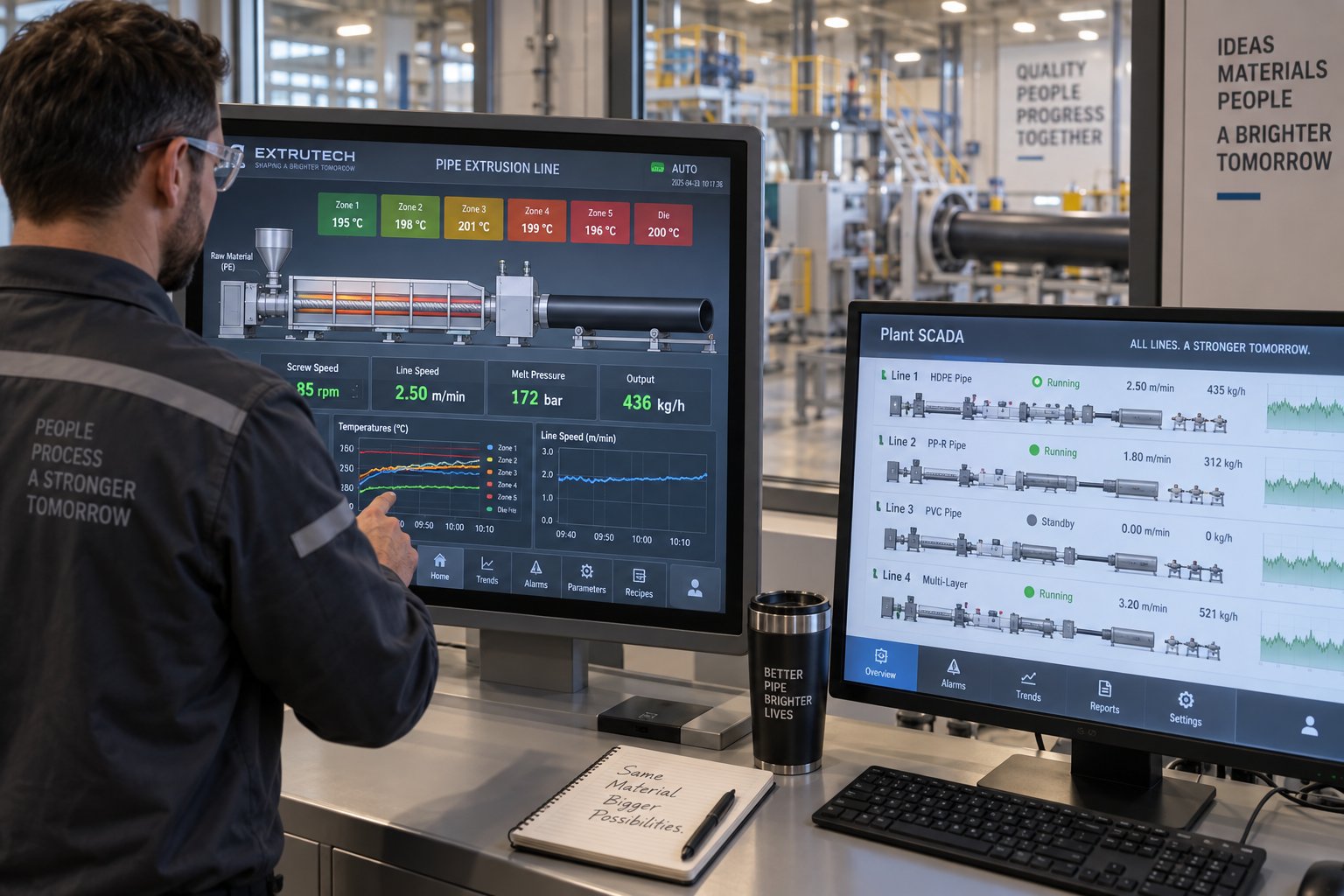
Automation and Control Systems in Modern PE Pipe Extrusion Lines
Every component discussed so far — extruder, die head, vacuum tank, cooling baths, haul-off, cutter — is a powerful piece of hardware. But hardware alone does not make good pipe. What ties these discrete stations into a unified, precision manufacturing system is the control layer sitting on top of them: programmable logic controllers, human-machine interfaces, measurement sensors, and the software algorithms that translate raw data into real-time process corrections. Without that layer, even the most expensive hdpe pipe extrusion machine is only as consistent as the operator running it — and as industry experience consistently demonstrates, human judgment alone cannot match the speed and precision of automated closed-loop control.
PLC Control, SCADA, and HMI Interfaces
At the heart of every modern extrusion line sits a programmable logic controller — or PLC — that acts as the central nervous system. The PLC receives input signals from dozens of sensors distributed along the line (temperature probes, pressure transducers, speed encoders, vacuum sensors, gauge outputs) and sends output commands to drives, heaters, valves, and actuators. All of this happens in scan cycles measured in milliseconds, far faster than any operator could read a gauge and turn a dial.
Operators interact with the PLC through a touchscreen HMI (human-machine interface) panel, typically mounted at the extruder station with secondary panels at the haul-off and cutter. From the HMI, you can:
- Set and monitor barrel temperature zones, die head temperatures, and melt pressure
- Adjust screw RPM and view real-time extruder output in kg/h
- Control haul-off speed in m/min and observe the live relationship between output and pull speed
- Set vacuum levels in the calibration tank and cooling water temperatures
- Program cutting lengths, coil sizes, and end-of-line handling sequences
- Store and recall complete recipes — temperature profiles, speed setpoints, vacuum targets — for every pipe dimension and PE grade the line produces
Recipe management is one of the most underrated features of PLC-based control. Instead of relying on an operator to remember that PE100 SDR 11 in 110 mm OD needs barrel zone 3 at 215 degrees, haul-off at 2.8 m/min, and vacuum at negative 0.035 MPa, the system stores every parameter in a named recipe that can be loaded with a single button press. This eliminates the shift-to-shift variability that plagues lines without centralized recipe storage — a variability that scrap-reduction specialists identify as one of the most common sources of startup waste and changeover rejects.
Above the PLC level, larger factories deploy SCADA (Supervisory Control and Data Acquisition) systems that aggregate data from multiple extrusion lines into a single supervisory platform. A SCADA dashboard gives production managers and quality engineers a real-time bird's-eye view of every line on the floor — output rates, alarm histories, dimensional trends, energy consumption — without leaving their office. More importantly, SCADA systems log every parameter continuously, creating a complete production record for each pipe lot. This traceability is not optional for producers supplying pipe under ISO 4427, ISO 4437, or gas-industry specifications where regulators can demand proof of process control for any delivered batch.
Automatic Wall Thickness Control and Gravimetric Dosing
Imagine you are running a 250 mm PE100 pressure pipe with a nominal wall thickness of 22.7 mm. The specification allows a tolerance of roughly plus 2.3 mm but zero on the minus side — you cannot ship pipe with a wall thinner than the minimum design value. Without automatic control, operators tend to run "fat" — deliberately targeting a wall 5 to 8 percent above nominal to create a safety buffer against unmeasured drift. That buffer is pure wasted resin, adding cost to every meter produced.
Closed-loop wall thickness control eliminates that buffer by measuring and correcting continuously. Here is how it works:
- Ultrasonic wall thickness gauges, positioned inside the vacuum calibration tank or immediately downstream, send sound pulses through the pipe wall and calculate thickness from the transit time between reflected interfaces. These measurements update multiple times per second, tracking the wall around the full circumference.
- The gauge transmits a stream of directional signals — essentially "wall is thickening" or "wall is thinning" relative to the programmed target — back to the PLC-based gauge control unit inside the haul-off.
- The gauge control interprets those signals and issues incremental speed commands to the haul-off servo motor. If the wall is thickening, the puller incrementally increases speed to stretch the soft extrudate slightly and thin the wall back toward target. If the wall is thinning, the puller slows, allowing more material to accumulate per unit length.
- Simultaneously, a separate control loop monitors outside diameter via a laser scanner positioned at the cooling tank exit. When OD drifts, the system adjusts vacuum level — reducing vacuum to compress an oversized pipe or increasing it to expand an undersized one — using servo-controlled valves that respond in milliseconds rather than the minutes a manual adjustment would require.
These loops run in parallel, each refining a different aspect of the pipe's geometry without interfering with the other. As extrusion control engineers explain, the key is that successive loops progressively improve the final result: the extruder-to-puller speed loop establishes gross dimensional stability, the wall thickness loop trims out the sine-wave variations inherent in extruder output, and the OD-to-vacuum loop provides the final fine-tuning that locks dimensions to tight tolerances. The result is such close coordination that discrete equipment behaves as though it is fully integrated.
On the material-input side, gravimetric dosing systems apply the same closed-loop philosophy to additive feeding. Load cells continuously weigh the resin and masterbatch streams entering the extruder, and a dedicated controller adjusts feeder speed in real time to maintain the target blend ratio — typically within plus or minus 0.5 percent. For a pp pipe extrusion line or ppr pipe extrusion line handling specialty additives at low inclusion rates, this precision is even more critical, because small dosing errors in UV stabilizer or antioxidant concentration can push the finished product out of specification without any visible defect at the line.
How Automation Reduces Scrap and Improves Consistency
Where does scrap actually come from on a PE pipe line? Rarely from steady-state production. The real damage happens during transitions — startups, shutdowns, grade changes, dimension changes, and the brief moments when a coiler hands off or a saw fires. These are the windows where process parameters shift rapidly and human reaction time cannot keep pace.
Industry data shows that product changeovers alone commonly consume 30 to 60 minutes of transition material, and two grade or dimension changes per day can generate one to two hours of scrap and downtime. For lines running high-cost PE100 or PE-RT resin, that waste erodes margins fast.
Automation attacks scrap at its source — by removing the dependency on operator speed and judgment during the moments that matter most:
- Recipe-driven startups — loading a stored recipe sets every parameter simultaneously, eliminating the sequential trial-and-error approach where an operator adjusts temperature, then speed, then vacuum, then waits to see the result. Automated systems can ramp through a validated startup sequence in a fraction of the time, reaching specification pipe faster and discarding less material.
- Automatic dimension changes — when switching from one pipe size to another, the PLC coordinates haul-off speed, extruder output, vacuum level, and cutting length changes in a single synchronized transition rather than a series of disconnected manual adjustments.
- Closed-loop wall thickness correction — where an operator may require one to three minutes to make a single measurement, calculate the needed adjustment, and wait for the result, automated systems make multiple, finely tuned adjustments in the same time frame, perfecting the product much faster and producing far less out-of-spec pipe during any disturbance.
- Out-of-spec segment identification and removal — advanced control systems use synchronized speed and distance data from the haul-off encoder, combined with dimensional measurements from laser and ultrasonic gauges, to track exactly which segments of pipe fell outside tolerance. The cutter can then isolate and reject those segments automatically, preventing defective product from reaching the stacker or coiler.
- Alarm management and trend logging — the PLC continuously monitors every parameter against programmed limits and triggers visual and audible alarms the instant any value drifts outside its acceptable band. Trend logs allow quality engineers to identify slowly developing issues — gradual screw wear, drifting heater output, cooling water temperature creep — long before they produce visible defects.
Practical Advice: Daily Monitoring and Startup/Shutdown Sequences
Automation handles the millisecond-to-millisecond corrections, but operators still own the daily discipline that keeps the system performing at its best. Here are the parameters worth watching on every shift:
- Melt pressure at the die inlet — a gradual rise at constant screw speed can indicate screen pack blockage or material viscosity changes. A gradual drop may signal screw or barrel wear increasing leakage flow.
- Barrel zone temperatures versus setpoints — consistent deviation in a single zone often points to a failing heater or thermocouple before it triggers an alarm.
- Haul-off speed stability — servo-driven haul-offs should hold speed within fractions of a percent. Any oscillation visible on the trend screen deserves immediate investigation.
- Vacuum level trend in the calibration tank — gradual loss of vacuum can indicate water seal degradation, pump wear, or a leak in the tank's seal gaskets.
- Gravimetric dosing accuracy — check the controller's actual-versus-target readout at the start of each shift. A drift beyond plus or minus one percent warrants recalibration.
- Cooling water temperature — even a 2 to 3 degree rise in supply water temperature can shift pipe crystallization behavior and affect dimensional stability, especially during warm-season operation.
For startups and shutdowns, two practices deliver the most consistent scrap reduction. First, purge before shutdown — while the machine is still producing acceptable product. Clearing residual degraded material from the barrel and die at the end of a run eliminates contamination-driven scrap at the next startup. Second, follow a structured ramp sequence: bring barrel zones to target temperature before starting the screw, allow melt pressure to stabilize before engaging the haul-off, and confirm dimensional readings are within tolerance before directing pipe to the stacker or coiler. Skipping these steps in the interest of speed invariably produces more transition scrap than the time saved.
Taken together, PLC control, closed-loop measurement, gravimetric dosing, and disciplined operating procedures form an integrated system that does far more than reduce scrap. They transform the extrusion line from a collection of machines requiring constant human intervention into a self-correcting manufacturing platform — one capable of holding tight tolerances shift after shift with minimal operator dependency. That consistency is ultimately what determines whether a line delivers a profitable return or slowly bleeds margin through waste, rework, and quality complaints. And it is precisely this total-system perspective — automation included — that should guide anyone evaluating a new line purchase or planning a long-term upgrade strategy.
How to Evaluate and Select the Right PE Pipe Extrusion Line
Automation, die precision, and screw-barrel metallurgy all matter — but they only matter if the line you purchase actually matches your production reality. Too many buyers fixate on the extruder's maximum throughput number in a brochure, sign a purchase order, and then discover that the cooling section bottlenecks at their most common pipe size, or that the control system cannot be expanded when they add a co-extruder two years later. A structured evaluation process prevents those expensive surprises.
Whether you are sourcing your first hdpe extruder machine or replacing a line that has run its course, the framework below will help you compare options on the dimensions that actually drive long-term profitability — not just sticker price.
Key Specifications and Performance Benchmarks to Evaluate
Every manufacturer will hand you a datasheet. The challenge is knowing which numbers to interrogate and which questions expose the gap between theoretical capability and real-world performance. Start with this checklist:
| Evaluation Criterion | What to Ask the Manufacturer | Why It Matters |
|---|---|---|
| Pipe diameter range | What is the full OD range the line can produce with available tooling? What tooling changes are needed at each size step? | Determines product flexibility. A line rated for 20–630 mm may require different calibration sleeves, die inserts, and haul-off pads for each range segment. |
| Maximum wall thickness | What is the thickest wall achievable at the largest diameter, and what cooling length does that require? | Heavy-wall extruded hdpe pressure pipe (e.g., SDR 11 at 630 mm) demands significantly more cooling capacity than thin-wall drainage pipe of the same OD. |
| Output rate (kg/h) | Provide output data for the specific pipe size, wall thickness, and PE grade I plan to run — not just the extruder's theoretical maximum. | A useful production proposal should clearly show output in kg/h, line speed in m/min, and the pipe size used for the calculation. Generic maximums mislead buyers into oversizing or undersizing. |
| Line speed (m/min) | What is the sustainable line speed at my target pipe size and wall thickness? | Line speed, not extruder RPM, determines how many meters you ship per shift. It is always constrained by the weakest downstream link — usually the cooling section. |
| Energy consumption (kWh/kg) | What is the measured energy consumption per kilogram of finished pipe at my target production conditions? | Energy is the largest variable operating cost. Even a 10 percent efficiency difference compounds over years of continuous production. Energy use should be evaluated together with production output — a more powerful motor is not automatically less efficient if it produces substantially more finished product. |
| Control system brand and expandability | Which PLC platform and HMI software does the line use? Can additional I/O modules, co-extruder control, and inline gauging be integrated later? | A proprietary or discontinued control platform traps you into a single vendor for upgrades and support. Industry-standard PLC brands (Siemens, Allen-Bradley, Omron) offer broader spare-parts availability and third-party integration. |
| Screw and barrel specification | What is the screw L/D ratio, compression ratio, and barrel metallurgy? Is the barrel bimetallic or nitrided? | These specifications directly determine melt quality, energy efficiency, and component lifespan. An hdpe pipe extruder machine with a nitrided barrel will wear significantly faster than one with a bimetallic alloy lining when processing pigmented or recycled compounds. |
Match every specification to your actual production plan — not your aspirational one. A line sized for 500 kg/h that routinely runs at 200 kg/h wastes energy, depreciates faster per kilogram produced, and ties up capital that could be working elsewhere.
Questions to Ask Manufacturers Before Purchasing
A polished sales presentation is not a substitute for detailed technical answers. Before signing any purchase order, work through these questions — and pay close attention to how specifically the manufacturer responds:
- Screw-barrel metallurgy and warranty — What alloy is used for the barrel lining and screw hard-facing? What is the warranty period on wear-related components, and what wear threshold triggers a warranty claim?
- Control system documentation — Will you provide full electrical schematics, PLC program backups, and HMI source files? Can I engage a third-party integrator for future modifications?
- Spare parts availability and lead times — Do you maintain a recommended spare-parts list? What are typical lead times for critical items like heaters, thermocouples, screen packs, and die components? Spare-parts procurement for older or unsupported lines can average three to eight weeks per order, so understanding the supply chain before you buy is essential.
- Factory acceptance test (FAT) scope — Will you run the line at my specified pipe size, wall thickness, and PE grade during the FAT? What parameters will be measured, and what acceptance criteria apply?
- Installation support and commissioning — How many engineers will be on-site, for how many days? Does commissioning include optimizing process parameters for my specific resin, or only verifying that the equipment powers on?
- Operator and maintenance training — Is training conducted on my actual line with my materials, or is it classroom-only? Does training cover preventive maintenance schedules and troubleshooting procedures?
- Tooling and mold inclusion — Does the quoted price include all die inserts, calibration sleeves, haul-off pads, and cutting tooling for my diameter range, or are these priced separately? A low quotation may exclude essential components that must be purchased later.
- Reference installations — Can you provide contact details for customers producing similar pipe products on the same line model? Ask to see production videos or testing records from comparable projects.
Manufacturers who answer these questions with specifics — alloy grades, warranty durations, FAT protocols — demonstrate engineering depth. Vague or evasive responses are a red flag, regardless of how competitive the price appears.
Planning for Long-Term Operation and Component Replacement
The purchase price of a pe pipe extrusion line is only the opening chapter of its total cost story. Over a typical 15-to-20-year service life, the cumulative spend on energy, maintenance, wear parts, and unplanned downtime routinely exceeds the original capital investment. Planning for that reality from day one separates factories that run profitably decade after decade from those that lurch from breakdown to breakdown.
Three principles guide long-term operational planning:
- Preventive maintenance scheduling — establish baseline measurements for every wear-prone component at commissioning. Record screw flight diameters, barrel bore dimensions, die gap settings, and haul-off belt thickness. Re-measure at fixed intervals (typically every 2,000 to 4,000 operating hours for screws and barrels) and plot the wear trend. Replacing a component proactively — before it degrades output quality — avoids the far more expensive scenario of discovering a problem only after a customer rejects a shipment.
- Sourcing quality replacement wear parts — not all replacement screws and barrels are created equal. A low-cost generic barrel may save money on the purchase order but cost multiples in shortened service life, reduced throughput, and inconsistent melt quality. When sourcing replacement single screw barrels for an hdpe extruder machine, look for suppliers who engineer barrels to match your specific application — pipe diameter range, PE grade, output target — rather than offering one-size-fits-all commodity parts. NANHAIYA, for example, specializes in custom and replacement single screw barrels engineered for pipe, film, sheet, pelletizing, and recycling extrusion lines, with bimetallic alloy options and screw geometries tailored to the demands of specific polymer families. That application-specific approach to component manufacturing is exactly what sustains peak line performance over years of continuous operation.
- Budgeting for component lifecycle costs — build a rolling replacement budget that accounts for the expected service life of each major wear item. Screws and barrels on a well-maintained PE pipe line typically last 15,000 to 25,000 hours before requiring rebuild or replacement, depending on the resin's abrasiveness and filler content. Die components, calibration sleeves, haul-off pads, and cutting blades have shorter cycles. Factoring these costs into your annual operating budget prevents the capital shock of an unplanned major replacement and ensures you always have the right parts available when the maintenance window arrives.
The factories that extract the most value from their extrusion lines are not necessarily the ones that bought the most expensive equipment. They are the ones that made informed purchasing decisions, maintained disciplined operating procedures, and treated component quality as a long-term investment rather than a short-term expense. Every chapter of this guide — from resin selection to die design, from automation architecture to screw-barrel metallurgy — feeds into that single, overarching principle: a PE pipe extrusion line is a system, and the quality of every output depends on the quality of every input, every day, for the life of the machine.
Frequently Asked Questions About PE Pipe Extrusion Lines
1. What are the main components of a PE pipe extrusion line?
A complete PE pipe extrusion line consists of a material feeding and dosing system, a single-screw extruder with a heated barrel, a spiral mandrel die head, a vacuum calibration tank with a precision sizing sleeve, spray or immersion cooling baths, a servo-driven caterpillar haul-off unit, a cutting station (planetary saw or rotary cutter), and end-of-line handling equipment such as automatic stackers or coilers. A PLC-based control system ties all stations together, coordinating temperatures, speeds, vacuum levels, and cutting lengths in real time. Every component must be capacity-matched to the others — an oversized extruder paired with an undersized cooling section forces the entire line to slow down, wasting both energy and throughput potential.
2. How is HDPE pipe manufactured in an extrusion line?
HDPE pipe manufacturing follows a continuous process. Polyethylene pellets and masterbatch are gravimetrically dosed into an extruder hopper. Inside the barrel, a rotating screw conveys the pellets through solid conveying, compression, and metering zones, converting them into a homogeneous melt at 190 to 230 degrees Celsius. The pressurized melt enters a spiral mandrel die that shapes it into an annular tube. This soft tube immediately passes into a vacuum calibration tank where negative pressure forces the outer wall against a precision-machined sizing sleeve, locking the outside diameter. Spray and immersion cooling baths then solidify the pipe fully. A haul-off unit pulls the cooled pipe at a constant speed — the ratio of extruder output to haul-off speed directly controls wall thickness — before a travelling saw cuts it to programmed lengths.
3. Should I choose a single-screw or twin-screw extruder for PE pipe production?
For standard polyethylene pipe production — including HDPE, MDPE, and PE-RT — a single-screw extruder is the recommended choice for most producers. Single-screw machines cost roughly one-half to one-third the price of a comparable twin-screw unit, offer simpler maintenance with fewer moving parts, and consume less energy per kilogram when processing polyolefins (typically 0.18 to 0.22 kWh/kg versus 0.22 to 0.30 kWh/kg for twin-screw). Twin-screw extruders earn their premium in PVC or CPVC pipe production, or when processing heavily recycled material and high-filler compounds that demand superior mixing capability. The critical factor for single-screw performance is screw and barrel quality — bimetallic barrels and optimized screw geometry matched to the PE grade determine output consistency and service life.
4. What PE resin grades are used for pipe extrusion and how do they differ?
The most common pipe-grade polyethylenes include PE100 (HDPE with MRS of 10 MPa for high-pressure water and gas mains), PE80 (HDPE/MDPE for medium-pressure pipelines), MDPE (for gas service lines and small-diameter water distribution), LDPE (for low-pressure irrigation and drainage), and PE-RT (for hot-water heating systems). These grades differ in melt flow index, density, and molecular weight distribution, which directly affect extrusion temperature profiles, screw speed settings, and cooling requirements. PE100, with its low MFI of 0.2 to 0.5 g/10 min, demands aggressive screw melting geometry and higher barrel temperatures (190 to 230 degrees Celsius), while LDPE processes at temperatures as low as 150 degrees Celsius. Choosing the wrong grade-to-equipment match leads to chronic dimensional problems that downstream adjustments cannot fully resolve.
5. How does vacuum calibration control PE pipe dimensions?
Vacuum calibration is the station that permanently sets a PE pipe's outside diameter and surface finish. The freshly extruded tube — still soft and molten — slides over a precision-machined sizing sleeve inside a sealed tank. A vacuum pump creates negative pressure (typically 0.02 to 0.05 MPa) in the tank, while atmospheric pressure inside the pipe pushes the outer wall outward against the sleeve. Cooling water sprays simultaneously harden the outer skin in place. Three variables determine dimensional accuracy: vacuum level (too low causes undersized OD; too high risks internal voids), cooling water temperature (15 to 20 degrees Celsius prevents thermal shock while ensuring solidification), and sleeve material and length (copper alloy or stainless steel, machined to tolerances within plus or minus 0.02 mm). Importantly, the calibration sleeve — not the die — defines the pipe's final outside diameter.
Written by
Nanhaiya Technical Team
Zhoushan Nanhaiya Plastic Machinery Co., Ltd.
The Nanhaiya technical team supports screw and barrel manufacturing projects through application review, technical communication, custom manufacturing coordination, and production and quality control.
Discuss Your Application
Related Articles
More insights on screw barrel technology and plastics processing.
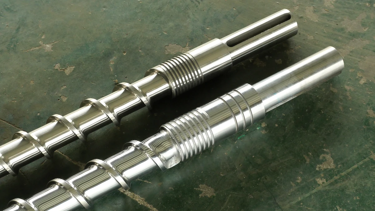
How The Wrong Extruder Screw Barrel For PP Ruins Your Melt
Oct 27, 2026
Learn why PP extrusion needs a purpose-built extruder screw barrel for PP — covering geometry, metallurgy, mixing elements, temperature profiles, and troubleshooting.
Read Article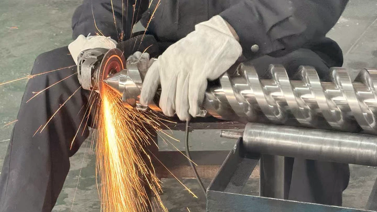
Plastic Extruder Screw Barrel Service: Match The Fix To The Wear
Oct 27, 2026
Learn how plastic extruder screw barrel service works — from zone-by-zone wear diagnosis and measurement methods to repair techniques, material matching, and maintenance scheduling.
Read Article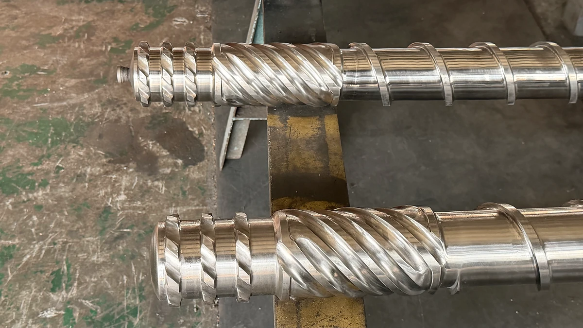
Extruder Screw Design: Match Your Polymer or Pay the Price
Oct 26, 2026
Extruder screw design guide covering geometry parameters, polymer-specific screw selection, mixing principles, wear-resistant materials, and a step-by-step design workflow.
Read ArticleLooking for something else?
Search by material, symptom or product and jump straight to the relevant page.
These are navigation suggestions based on keyword matching — not a quotation, not a delivery commitment, and not a substitute for engineering review. Final specification is confirmed by our engineers against your drawings and processed material.
Need help with screw barrel selection?
Share your machine model, processed material and application. Our team can help with pricing and technical support.