

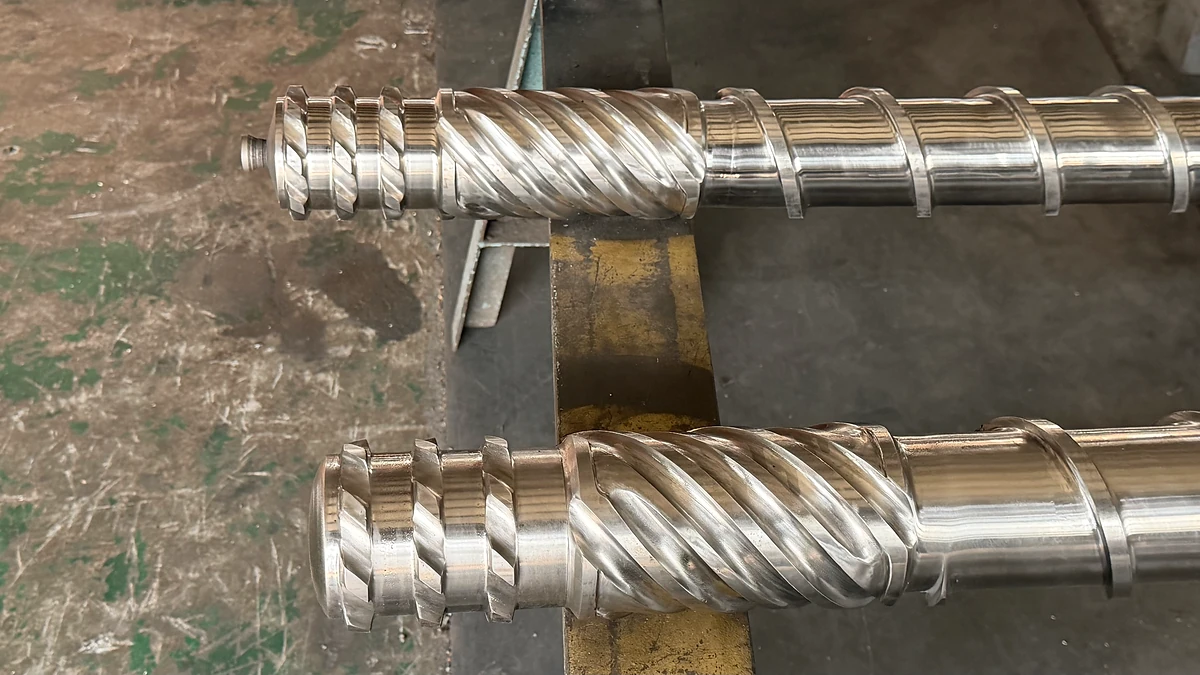
What Is Extruder Screw Design and Why Does It Matter
Imagine feeding polymer pellets into an extruder and expecting a flawless melt stream on the other end. What stands between raw resin and a quality product? A single rotating component — the extruder screw. Its design determines whether you get uniform output or a mess of gels, unmelts, and wasted energy.
Defining Extruder Screw Design and Its Role in Polymer Processing
Extruder screw design is the engineering discipline of selecting and optimizing screw geometry — channel depth, flight configuration, compression ratio, L/D ratio — along with zone layout and material composition to achieve target melt quality, throughput, and energy efficiency for a specific polymer and application. In practical terms, the screw barrel system acts as the heart of any extrusion line. Every rotation of the extruder screw governs four fundamental processes: solids conveying from the extruder feed barrel, melting through frictional and shear heating, mixing of additives or colorants, and pressurization of the melt toward the die.
As NC State Extension research highlights, configuring a screw for extrusion is a blend of art and science — no gold standard exists because every material exhibits unique flow properties influenced by temperature, shear rate, and extruder geometry. That complexity is exactly why this guide exists. It covers both single-screw and twin-screw systems, bridging geometry fundamentals through polymer-specific guidance, mixing principles, metallurgy, and a practical design workflow.
Why Screw Design Is the Most Impactful Variable in Extrusion
Barrel temperature profiles, die geometry, and downstream cooling all influence your final product. Yet the screw is the primary driver of melt homogeneity, residence time distribution, shear history, and output stability. A poorly matched screw creates defects — gels from incomplete mixing, unmelts from insufficient energy input, or degradation from excessive shear heating. It also wastes electricity and caps your throughput well below the extruder's potential.
The screw converts mechanical energy into thermal and pressure energy. Its geometry dictates how efficiently and uniformly that conversion occurs — making it the single most impactful variable in your entire extrusion process.
Think of it this way: you can fine-tune every temperature zone and perfect your die design, but if the screw delivers an inconsistent melt, those adjustments are just compensating for a root-cause problem. The real leverage point sits inside the barrel, turning with every RPM. And the geometry of that screw — its channel depths, flight widths, compression profile, and mixing sections — is where performance is won or lost.
The question, then, is not whether screw geometry matters. It is which specific parameters matter most, how they interact, and how you match them to your polymer. That starts with understanding the critical dimensions that define every screw profile.
Critical Screw Geometry Parameters Every Engineer Must Know
Every extrusion screw — whether it sits inside a profile line, a blown film tower, or injection molding screws and barrels — is defined by a handful of interdependent geometric dimensions. Change one, and you shift the balance of melting, mixing, and pressure generation across the entire process. The challenge is that these parameters never operate in isolation. Optimizing channel depth without considering compression ratio, or adjusting flight clearance without accounting for flight width, leads to screw profiles that underperform or, worse, damage the polymer.
Here is a systematic breakdown of the parameters that define every screw extrusion process, organized so you can see both their individual roles and their interactions.
L/D Ratio and Compression Ratio Fundamentals
The L/D ratio — screw flighted length divided by its outer diameter — is the first specification most engineers encounter. It sets the total real estate available for solids conveying, melting, mixing, and metering. According to veteran extrusion engineer Allan Griff, the most common L/D is around 24:1, with some designs stretching to 30:1 or longer, while a few run as short as 20:1. A longer L/D gives the polymer more residence time for complete melting and thorough mixing, but it also increases shear history, equipment cost, and the potential for thermal degradation in heat-sensitive resins.
The compression ratio describes the volume reduction the polymer undergoes as it travels from the feed zone to the metering zone. It is typically expressed as the ratio of feed channel depth to metering channel depth (on a constant-pitch screw). Most general-purpose screws fall in a range of roughly 2:1 to 4:1. A higher compression ratio squeezes the material more aggressively, generating greater frictional heating and pressure — ideal for highly crystalline polymers that need substantial energy to melt, but risky for shear-sensitive materials like PVC.
Here is the critical interaction: pairing a high compression ratio with a short L/D screw concentrates that volume reduction into fewer turns, creating intense and abrupt melting conditions. For thermally stable polyolefins, that may work fine. For an engineering resin with a narrow processing window, it can mean degradation before the melt even reaches the metering zone. Balancing these two parameters is the first major design decision for any extrusion screw.
Channel Depth, Flight Width, and Flight Clearance
Feed channel depth controls how much solid material the screw can accept per revolution. Deeper feed channels increase solids intake capacity — useful for low-bulk-density powders or regrind — but they also reduce the screw's structural rigidity. Metering channel depth, at the opposite end of the screw, determines the melt pumping rate and the shear rate the polymer experiences in its final zone before the die. Shallow metering channels generate higher shear and better mixing but lower throughput; deeper channels boost output but sacrifice shear intensity.
As Griff notes, compression ratio alone is an "indefinite number" and cannot properly describe a screw unless at least one channel depth is known. Two screws can share an identical 3:1 compression ratio yet deliver very different performance if one has a 10 mm feed depth and the other has a 6 mm feed depth.
Flight width — the thickness of the helical flight measured along the screw axis — is typically about 10% of the barrel diameter. Wider flights generate more pressure and seal better against backflow, but they also consume usable channel length and develop excess heat in the clearance zone. Narrow flights increase the channel area available for material transport but allow more leakage flow backward over the flight tip.
Flight clearance is the radial gap between the flight tip and the barrel wall. On new screws, this gap typically falls between 0.125 mm and 0.25 mm (0.005 to 0.010 in.), with smaller screws toward the tight end and larger screws toward the loose end. Tighter clearances improve sealing and reduce backflow leakage, but they increase localized shear heating and are more expensive to manufacture. As clearance grows through wear, the screw loses pumping efficiency — though Griff cautions that some wear beyond new-screw tolerances is often harmless and may even be beneficial.
The takeaway? These four dimensions — feed depth, metering depth, flight width, and flight clearance — form an interconnected system. Adjusting any one of them shifts the pressure profile, shear distribution, and throughput capacity of the entire screw. Optimizing them in isolation is a recipe for trial-and-error frustration.
Helix Angle and Number of Flights
The helix angle is the angle of the screw flight relative to a plane perpendicular to the screw axis. For a standard single-flight, square-pitch screw (where the pitch equals the diameter), this angle works out to approximately 17.66 degrees. A square-pitch layout is the most common configuration, and it simplifies L/D calculation — you can estimate L/D simply by counting flight turns, as each turn advances one diameter of axial length.
Increasing the helix angle (steeper pitch) boosts the axial conveying component but reduces the cross-channel flow that contributes to mixing. Decreasing it does the opposite — better mixing at the expense of forward conveyance. In twin-screw systems, pitch selection plays a similar role: larger-pitch conveying elements move material quickly with minimal shear, while smaller-pitch elements compress and build pressure.
The number of flights adds another layer of control. Most standard screws are single-flighted, but double-flighted designs split the channel into two parallel helical paths. This improves heat transfer to the melt and can reduce output pulsation, making double-flighted metering sections useful in applications like extrusion coating where very high and uniform melt temperatures are needed. Barrier screws — discussed in the next section — are inherently double-flighted in their barrier sections, with one channel dedicated to unmelted solids and the other to the melt pool.
Screw Geometry Parameter Reference
| Parameter | Definition | Typical Range | Practical Impact |
|---|---|---|---|
| L/D Ratio | Flighted screw length divided by outer diameter | 20:1 to 30:1+ (most common ~24:1) | Controls total residence time, melting capacity, and mixing opportunity |
| Compression Ratio | Feed channel depth divided by metering channel depth | 2:1 to 4:1 | Determines rate of volume reduction, pressure build, and shear intensity |
| Feed Channel Depth | Radial depth of screw channel in the feed zone | Varies by diameter and application | Sets solids intake capacity; deeper = more throughput potential |
| Metering Channel Depth | Radial depth of screw channel in the metering zone | Varies; shallower than feed zone | Controls melt pumping rate, shear rate, and mixing intensity |
| Flight Width | Axial thickness of the screw flight | ~10% of barrel diameter | Balances pressure generation against usable channel volume and heat buildup |
| Flight Clearance | Radial gap between flight tip and barrel wall | 0.125 to 0.25 mm (new screws) | Affects leakage flow, sealing efficiency, and localized shear heating |
| Helix Angle | Angle of flight relative to a plane perpendicular to screw axis | ~17.66° for standard square pitch | Influences conveying efficiency vs. cross-channel mixing balance |
| Number of Flights | Count of parallel helical channels | 1 (standard) or 2 (double-flighted / barrier) | Additional flights improve heat transfer, reduce pulsation, enable barrier separation |
These eight parameters form the geometric DNA of every extrusion screw. Individually, each one shifts a specific aspect of processing. Together, they define the screw's personality — how aggressively it melts, how thoroughly it mixes, and how consistently it delivers melt to the die. But geometry alone does not tell the whole story. How these parameters are distributed across the screw's length — organized into distinct functional zones — determines whether the design actually works for a given polymer. That zonal architecture is where geometry meets process strategy.
Three-Zone Screw Architecture and Advanced Geometries
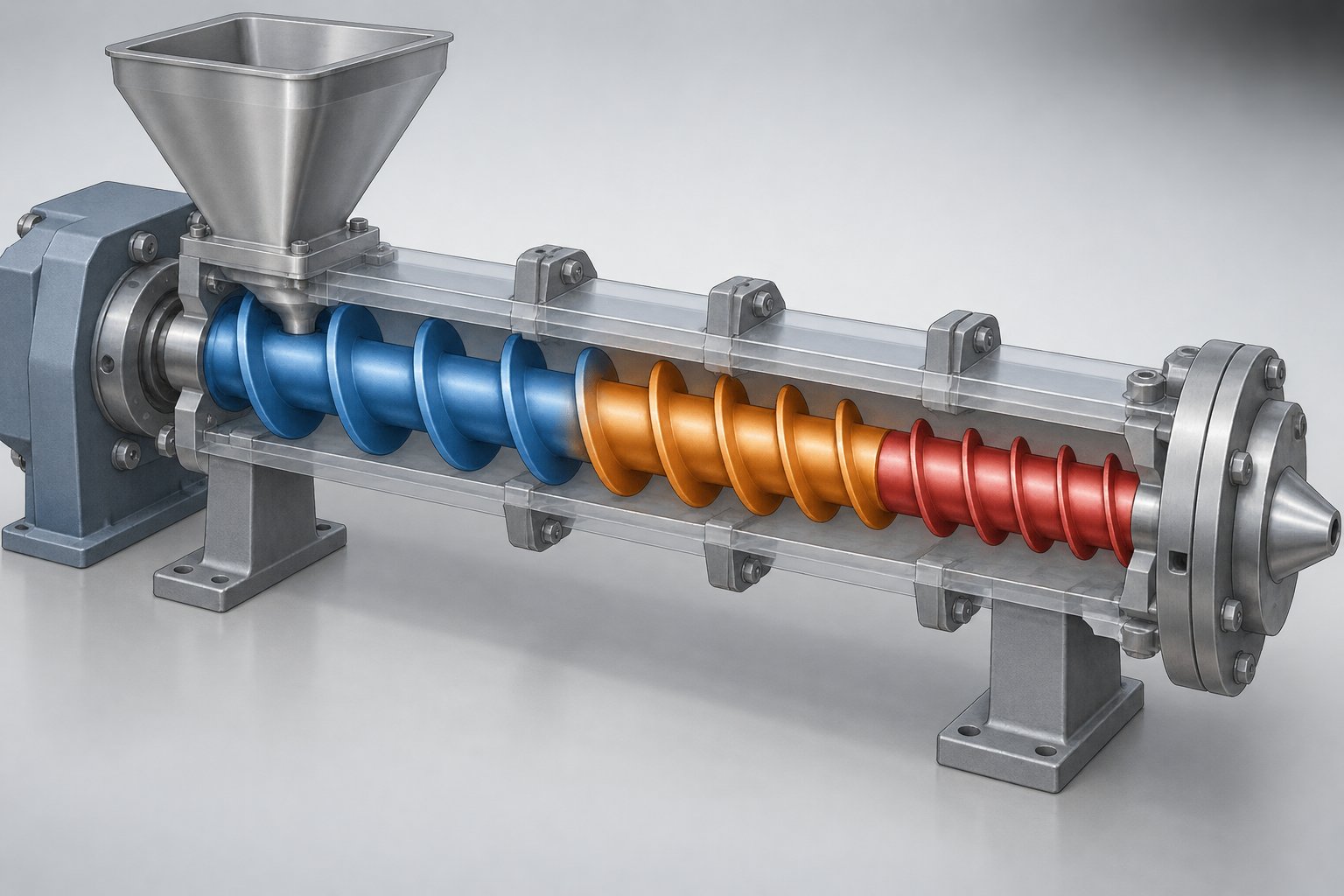
Every screw geometry parameter discussed above has to live somewhere along the screw's length. The question is where — and that is exactly what zone architecture answers. Virtually every single-screw extruder uses a foundational three-zone layout: feed, compression (transition), and metering. Each zone performs a distinct job, and the screw design within each zone reflects different priorities for channel depth, volume reduction, and shear intensity. Understanding this architecture is the difference between reading a screw drawing and actually knowing what it will do to your polymer.
Feed Zone Design and Solids Conveying Principles
The feed zone is where solid pellets or powder enter from the hopper and begin their journey forward. Its primary screw feature is a deep, constant-depth channel that maximizes solids intake capacity per revolution. As Addcomposites notes, this zone typically occupies 50-60% of the total screw length in a standard design, though the exact proportion varies by application and polymer.
Why so deep? The pellets at this stage are loose and contain significant air between particles. A deep channel accommodates that low bulk density while generating enough frictional drag against the barrel wall to push the material forward. Preheating begins here through conduction from the heated barrel and friction between pellet surfaces, but the goal is controlled compaction — not premature melting. If the polymer softens too early, it can "bridge" across the channel and block incoming material flow.
Here is where the barrel interface becomes a major design variable. The way extruder screws and barrels interact at the feed section fundamentally changes the conveying mechanism. Most single-screw extruders use a smooth-bore feed throat — essentially a polished pipe surrounding the screw. In this configuration, solids transport depends almost entirely on the friction of polymer particles against the barrel wall. As extrusion specialist Jim Frankland explains, feed efficiency in smooth-bore systems typically reaches only 15% to 30% of the channel volume because of particle slip on the barrel surface. Output is sensitive to head pressure: as die resistance increases, pressure-driven backflow reduces throughput and raises melt temperature.
Grooved feed barrels take an entirely different approach. Machined grooves in the feed-throat wall physically lock the solid polymer particles, preventing rotation and dramatically increasing conveying efficiency. The compacted polymer forms a pressurized spiral plug that the screw flights wedge forward, generating feed-throat pressures that can exceed 12,000 psi. In a real-world comparison Frankland observed on a 90-mm extruder processing fractional-melt HDPE with barrier screws, the grooved-feed machine produced 563 lb/hr versus 445 lb/hr for a comparable smooth-bore unit at the same screw speed — a 26.5% output increase with a 27°F drop in melt temperature.
That performance gain sounds compelling, but grooved feed throats carry significant constraints that reshape screw design downstream. Here is how the two systems compare in terms of their implications for overall screw geometry:
- Smooth-bore feed: Output is coupled to screw speed and head pressure. Higher back pressure reduces throughput and increases melt temperature. Screw design follows conventional compression ratio guidelines (typically 2.5:1 to 4:1 depending on polymer). General-purpose and flexible — handles pellets, regrind, powders, and soft polymers without issue.
- Grooved feed: Output is largely decoupled from head pressure and screw speed, because feed-section pressure often meets or exceeds die pressure. Downstream screw geometry must accommodate the already-compacted, high-pressure solid plug — typically requiring lower compression ratios to avoid excessive pressure buildup. Requires intensive cooling of the feed section to prevent premature melting. Sensitive to particle shape and size; generally unsuitable for regrind, powders, or soft polymers like TPEs that can plug the grooves. Demands a specially designed screw — a smooth-bore screw will not work in a grooved-feed barrel and vice versa.
The feed zone, then, is not just a passive conveyor. Its screw design and barrel interface set the pressure profile, throughput ceiling, and solids compaction state that every downstream zone inherits.
Compression Zone and Melting Mechanisms
As compacted solids leave the feed zone, they enter the compression (or transition) zone — where the real transformation happens. This zone's defining screw feature is a progressively decreasing channel depth that reduces the available volume, forcing the solid bed against the heated barrel wall. The result is a combination of frictional heating, conductive heat transfer, and viscous shear that drives the melting process.
Imagine squeezing a block of ice against a warm surface. The contact face melts first, forming a thin liquid film. That film gets swept away, exposing fresh solid to the heat source. This is essentially the Tadmor melting model — developed by Zehev Tadmor in the 1960s and still the foundational framework for understanding single-screw melting. In this model, a thin melt film forms at the barrel wall and is dragged by barrel rotation into a growing melt pool on one side of the channel. The solid bed, meanwhile, narrows progressively along the screw length as more material melts from its barrel-facing surface.
A well-designed compression zone manages this process so that the solid bed is completely consumed before the material enters the metering zone. Too aggressive a compression — steep channel depth reduction over a short distance — and you overshear the polymer, generating excessive heat that can degrade sensitive resins. Too gradual, and unmelted solids survive into the metering section, causing gels, unmelts, and inconsistent output. The compression zone typically occupies 20-30% of the screw length, though this varies by polymer and application. Semi-crystalline resins with high heats of fusion, like HDPE, generally need more compression energy than amorphous resins that soften gradually.
Air removal is another critical function here. As the channel volume decreases, trapped air between pellets is squeezed backward toward the feed throat. If the compression is too abrupt or the solids are not properly compacted in the feed zone, air can become entrapped in the melt — showing up as voids, bubbles, or surface defects in the final product.
Metering Zone and Melt Quality Control
The metering zone is the final section of the screw, and its job is deceptively simple: deliver a homogeneous, thermally uniform melt at consistent pressure to the die. In practice, this is where output stability and melt quality are either confirmed or compromised.
This zone features a constant, shallow channel depth — the shallowest section of the entire screw. That shallow geometry serves two purposes. First, it creates a high shear rate that homogenizes any remaining temperature or composition variations in the melt. Second, it generates the pressure needed to push the polymer through the breaker plate, screen pack, and die. The metering channel depth is the critical dimension controlling output rate: deeper metering channels increase throughput but reduce shear intensity and mixing quality; shallower channels improve homogeneity at the cost of lower output.
For many applications, a conventional three-zone screw design delivers acceptable results. But when higher performance is required — better melting efficiency, higher throughput without overheating, or improved melt uniformity — engineers turn to barrier screw designs. A barrier screw introduces a secondary flight (the barrier flight) within the transition zone that physically separates the solid bed from the melt pool. The barrier flight has a slightly smaller diameter than the main flight, creating a clearance that allows molten polymer to pass over it into a dedicated melt channel while preventing unmelted solids from crossing.
This screw blade configuration improves melting efficiency because the solid bed maintains maximum contact with the barrel wall throughout the barrier section, rather than being partially insulated by its own melt pool. The result is faster, more complete melting at lower melt temperatures — which is exactly why barrier screws are the standard in demanding applications like HDPE blown film and pipe extrusion, particularly when paired with grooved feed barrels.
The three-zone architecture and its barrier-screw evolution represent screw design philosophy for a single continuous channel. Yet not all extrusion challenges are best solved with one screw. When intensive mixing, modular flexibility, or reactive processing enters the picture, a fundamentally different platform — and a different design logic — comes into play.
Single-Screw vs. Twin-Screw Extruder Design Compared
A single continuous channel shaped by zone architecture and barrier flights handles a wide range of polymer processing tasks. But what happens when the job demands intensive compounding, multi-ingredient blending, devolatilization, or reactive processing inside the barrel? That is where two screws — not one — change the entire design equation. The distinction between a single screw extruder and a twin-screw system is not just a matter of hardware count. These platforms represent fundamentally different philosophies for how material moves, melts, and mixes.
The choice between single-screw and twin-screw is a platform decision that precedes detailed screw geometry design. Get this wrong, and no amount of channel-depth optimization will fix the mismatch.
Single-Screw Design Philosophy and Strengths
A single screw extruder operates on drag flow. The polymer moves forward because friction between the material and the barrel wall creates a viscous drag that pushes the melt along the helical channel. Picture pulling a rope through a tube — the wall does the work, and the channel geometry controls how fast and under what pressure the material travels. This mechanism is elegant in its simplicity and remarkably effective for its core mission: continuous melt pumping of pre-compounded materials at steady pressure.
That simplicity translates into real operational advantages. Single-screw systems cost less to purchase and maintain, require less operator training, and deliver excellent pressure generation for downstream shaping operations. Profile extrusion, blown and cast film, sheet production, pipe and tubing lines, and wire coating all rely overwhelmingly on single-screw platforms. As Phoenix Equipment notes, single-screw machines remain widely used because they provide steady production with relatively straightforward mechanical construction.
Design optimization for single-screw systems focuses on the balance between melting efficiency, melt homogeneity, and output stability — the three-zone and barrier-screw concepts discussed earlier. You are fine-tuning a single continuous flow path, adjusting compression profiles, adding mixing sections like Maddock mixers, and selecting barrier geometries to improve melting. The design process is holistic but fundamentally linear: material enters one end, proceeds through sequential zones, and exits the other.
The limitation? Mixing capability is inherently moderate. Material stays within one helical channel, and cross-channel flow is the only natural mixing mechanism. Specialized mixing elements help, but they are additions to the conveying geometry — not the foundation of it. When you need to blend multiple ingredients, disperse nano-scale fillers, or strip volatile compounds from the melt, drag flow alone starts running into walls.
Twin-Screw Design Philosophy and Modular Elements
Twin-screw extruders — particularly co-rotating intermeshing designs — flip the script entirely. Instead of relying on wall friction to push material through a fixed channel, two screws intermesh to create positive displacement conveying. Material is physically transferred from one screw channel to the other, split, recombined, and transferred again. This repeated division and recombination is what gives twin-screw extruder design its signature mixing intensity.
The real power, though, lies in modularity. Where a single-screw design is typically machined as one continuous piece, a co-rotating twin screw extrusion system assembles individual screw elements onto splined shafts. These elements come in distinct categories, each performing a specific function. NC State Extension research classifies them into several key types:
- Conveying elements: Deep-flighted segments that move material forward with minimal shear. Larger-pitch elements (like SK 40/40) transport bulk material quickly, while smaller-pitch elements (like SE 20/20) build pressure and compress the melt.
- Kneading blocks: Stacked disc-shaped elements offset at specific angles. Screw blade configuration here controls both the type and intensity of mixing. Forward-staggered kneading blocks provide moderate mixing with forward conveyance. Neutral (90-degree) blocks halt forward movement, increasing residence time and energy input. Reverse-staggered blocks push material backward, creating maximum restriction and shear.
- Reverse elements: Left-handed conveying segments that slow or block material flow, creating backpressure upstream of vent ports or mixing zones.
- Toothed mixing elements: Specialized segments that combine forward conveyance with distributive mixing, useful for blending solids and liquids before the compression zone.
Imagine building with blocks rather than carving from a single piece of steel. You can rearrange these elements along the shaft to create a custom screw profile tailored to your exact process. Need more dispersive mixing for a pigment masterbatch? Add wider kneading blocks (like KBW elements) at the melting zone. Need a devolatilization section? Place reverse elements to create a melt seal before a vent port, then follow with deep conveying elements to reduce fill and expose surface area for volatile removal.
This screw element design flexibility extends to the barrel as well. Twin-screw barrels are typically segmented, allowing engineers to position feed ports, vent openings, side stuffers for downstream filler addition, and liquid injection points wherever the process requires them. The entire system — screws and barrel — can be reconfigured without buying a new machine.
The trade-off? Complexity and cost. Twin-screw gearboxes must distribute high torque across two closely intermeshing shafts, making them mechanically intricate and expensive. Maintenance involves more components, tighter tolerances, and a deeper understanding of how each element arrangement affects the process. As one industry comparison notes, twin-screw granulators typically cost two to three times more than comparable single-screw units, largely due to the gearbox precision, modular screw materials, and sophisticated control systems involved.
When to Choose Single-Screw vs. Twin-Screw Extrusion
So which platform fits your application? The answer almost always starts with the process duty — what the material needs to undergo inside the barrel. If the formulation is already prepared and the primary task is melting, pumping, and shaping, a single-screw extruder is typically the practical and cost-effective choice. If the process requires intensive mixing, multi-point ingredient addition, devolatilization, or reactive processing, a twin-screw system earns its higher price tag.
Here is a side-by-side comparison to guide that decision:
| Selection Criteria | Single-Screw Extruder | Twin-Screw Extruder |
|---|---|---|
| Primary Process Role | Melting, pumping, and shaping pre-compounded materials | Compounding, mixing, devolatilizing, and formulation development |
| Typical Applications | Film, sheet, pipe, profile, tubing, wire coating | Polymer compounding, masterbatch, filled compounds, reactive extrusion, recycling of complex waste streams |
| Mixing Capability | Moderate; improved with add-on mixing sections | High and fully configurable through element selection |
| Modular Flexibility | Low — screw typically machined as a single piece | High — elements rearranged on splined shafts; barrel segments interchangeable |
| Feeding Method | Typically flood-fed from hopper | Usually starve-fed via gravimetric feeders for precise rate control |
| Venting / Devolatilization | Available on vented-barrel designs but limited | Commonly integrated; multiple vent stations possible |
| Pressure Generation | Excellent — well suited for high-restriction dies | Moderate — may require gear pump for high-pressure applications |
| Equipment Cost | Lower for comparable size and output | Typically 2-3x higher due to gearbox, modular elements, and controls |
| Maintenance Complexity | Straightforward — fewer components, wider tolerances | Higher — more parts, tighter tolerances, element wear monitoring |
| Throughput Scalability | Scales well for single-material, high-volume runs | Scales well for multi-ingredient, variable-formulation operations |
Notice that neither platform is universally "better." A facility running millions of pounds of HDPE pipe resin per year through a well-optimized single-screw line has no reason to switch to a twin-screw system. Conversely, a compounder blending glass fiber, flame retardants, and impact modifiers into nylon would find a single-screw extruder painfully inadequate for the mixing and feeding demands involved.
Some modern recycling and compounding operations even combine both platforms in a two-stage system — using a single-screw extruder for initial melting and coarse filtration, followed by a co-rotating twin-screw for degassing, additive incorporation, and final homogenization. This hybrid approach captures the robust conveying of single-screw design and the mixing power of twin-screw technology in a single production line.
Selecting the right platform sets the stage, but it does not finish the job. The geometry of whatever screw sits inside that platform must still be matched to the specific polymer flowing through it — because polyethylene, PVC, nylon, and glass-filled compounds each impose very different demands on channel depth, compression rate, and shear tolerance.
How Polymer Properties Shape Screw Geometry Decisions
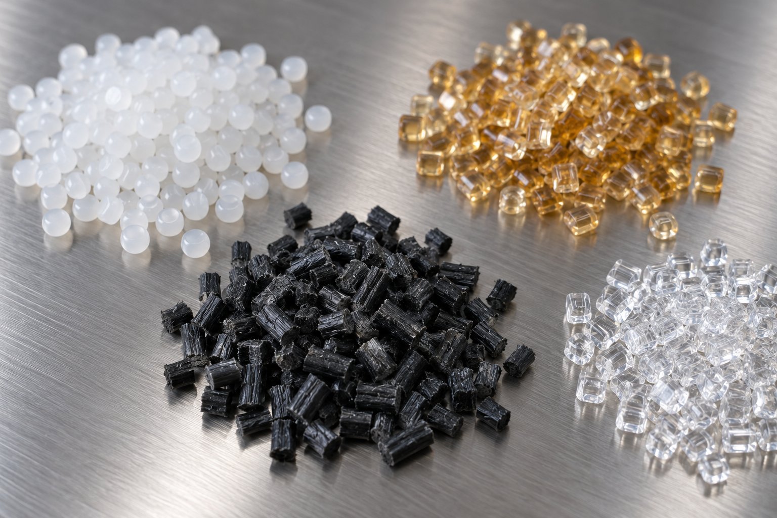
Choosing the right platform and understanding zone architecture gets you to the starting line. But here is where most extrusion engineers face the real challenge: the same screw geometry that runs beautifully with HDPE can destroy PVC in minutes and starve a glass-filled nylon of the mixing energy it needs. Every polymer family brings its own thermal behavior, melt rheology, and chemical sensitivities to the barrel — and polymer processing screw geometry must adapt accordingly.
Think of it this way. You would not use the same knife to slice bread and fillet a fish. The tool must match the material. Below is a polymer-by-polymer breakdown of how those material differences translate into concrete screw design decisions.
Polyolefin Screw Design for PE and PP Processing
Polyolefins — HDPE, LDPE, LLDPE, and PP — are semi-crystalline polymers with relatively high heats of fusion. Melting these materials requires substantial energy to break through their crystalline structures before the polymer transitions to a flowable melt. That energy demand is the defining factor in polyolefin screw design.
HDPE, with its higher crystallinity and density, needs more aggressive compression than LDPE or LLDPE. Experimental research by Jin et al. at Dow demonstrated this directly: for LLDPE pellets (bulk density ~590 kg/m3), a compression ratio of 2.8 proved optimal on a 63.5 mm smooth-bore extruder with a 21:1 L/D. Screws with lower compression ratios (2.0 and 2.4) could not develop sufficient channel pressure at low screw speeds, limiting throughput. Screws with higher compression ratios (3.2 and 3.6) generated excessive pressure in the transition section, increasing discharge temperatures by 5-10°C at higher speeds and producing more solid polymer fragments in the extrudate.
That same study revealed a critical throughput interaction. At screw speeds above 90 rpm, all screws with compression ratios of 2.8 and higher began discharging unmelted solid fragments — visible as translucent white streaks in the cross-sectioned extrudate. Why? Because doubling screw speed doubles solids conveying capacity, but the melting flux only increases by roughly 1.4 times. The barrel simply runs out of wall area to melt the incoming material. This mismatch is why polyolefin screws for high-output applications often use barrier flight designs, which maximize solid-bed contact with the barrel wall to boost melting efficiency without raising compression ratio further.
PP presents a related but distinct challenge. Its melting flux is lower than both LDPE and LLDPE at equivalent barrel temperatures, meaning PP screws typically need longer transition sections to provide more barrel surface area for melting. As the Dow research notes, running LDPE or LLDPE on a screw with a longer transition section designed for PP is commercially accepted practice — the extra melting length does no harm to the easier-melting resins.
The good news? Polyolefins are relatively thermally stable. Their broad processing windows tolerate higher shear rates and compression ratios compared to heat-sensitive polymers, giving designers more room to push throughput without risking degradation.
PVC Screw Design and Thermal Sensitivity Considerations
If polyolefins are forgiving, PVC is the opposite. This polymer has an extremely narrow processing window and begins degrading — releasing hydrochloric acid (HCl) and discoloring — if exposed to excessive heat or shear for even short periods. Every aspect of a PVC extrusion screw must reflect that sensitivity.
The core principle is simple: minimize shear, minimize residence time, and maintain gentle, uniform heating. In practice, that translates to several specific geometry choices:
- Low compression ratios: Typically 1.3 to 1.6 for rigid PVC — far below the 2.5-3.5 range common for polyolefins. This gentle compression avoids the frictional overheating that triggers degradation.
- Shallow channel depths: Both feed and metering channels are kept relatively shallow to limit the shear rates the melt experiences. Deep channels would create thick melt films with poor heat transfer and localized hot spots.
- Longer compression zones: Rather than compressing the material quickly over a few turns, PVC screws spread the transition gradually, allowing fusion to occur without abrupt pressure spikes.
- No barrier flights: Barrier screw designs create tight clearances and high localized shear at the barrier flight — exactly the conditions that degrade PVC. Standard single-flight or low-shear configurations are preferred.
- Lower L/D ratios: Shorter screws reduce total residence time in the heated barrel. Every extra second of heat exposure is a risk with PVC.
It is worth noting that rigid PVC is most commonly processed on counter-rotating twin-screw extruders — either conical or parallel designs — rather than single-screw machines. These systems offer superior control over shear input and melt pressure stability. Single-screw extruders are typically reserved for flexible (plasticized) PVC and simpler product geometries where shear sensitivity is less acute.
PVC compounds also include stabilizers, lubricants, and often calcium carbonate fillers — all of which affect screw wear. Hard chrome plating or corrosion-resistant coatings on the screw are standard practice to handle the HCl released during processing and the abrasive action of mineral fillers. Sounds like a lot to manage? It is. PVC extrusion is arguably the most design-constrained polymer family in the industry.
Engineering Thermoplastics and Filled Compound Screw Design
Engineering thermoplastics — nylon (PA), PET, polycarbonate (PC), and their reinforced variants — each present unique challenges that push screw design for filled compounds in specialized directions.
Nylon (PA6 and PA66) is hygroscopic. It absorbs atmospheric moisture readily, and that moisture causes hydrolytic degradation at processing temperatures, producing bubbles, reduced molecular weight, and poor mechanical properties. Screw design for nylon must account for this reality. Even with thorough pre-drying, vented extruder barrels with dedicated degassing zones are common for nylon processing. The screw profile needs a decompression section upstream of the vent port — where channel depth increases to reduce fill level and allow volatiles to escape — followed by recompression to build pressure toward the die. Nylon's moderate to high crystallinity also requires adequate compression energy, with compression ratios typically in the 3.0 to 3.5 range.
PET shares nylon's moisture sensitivity but adds an additional constraint: it is extremely prone to thermal degradation through hydrolysis and acetaldehyde generation. Residence time must be kept to an absolute minimum. Screw designs for PET favor moderate compression ratios with efficient melting sections that get the job done quickly, paired with vented barrels for moisture removal. Any dead spots in the screw channel — areas where material stagnates — risk generating degraded resin and discolored specks in the product.
Polycarbonate (PC) processes at high melt temperatures (280-320°C) and has a relatively wide processing window. Research at Dow has shown that PC's melting flux actually increases with higher melt flow rate — a counterintuitive finding attributed to thinner melt films forming between the solid bed and barrel wall for lower-viscosity grades. This means PC screws can be designed with relatively aggressive compression and standard barrier geometries, though care must be taken to avoid moisture-related degradation similar to nylon and PET.
Glass-fiber-reinforced compounds introduce extreme abrasive wear as the dominant design constraint. Glass fibers — which constitute 95% of all reinforcement fibers used in plastics — are harder than standard tool steels and erode screw flights, barrel walls, and mixing elements rapidly. Screw material selection becomes as critical as geometry: hardened tool steels, tungsten carbide coatings, and bimetallic barrels are essential for any production run involving glass-filled materials. Screw geometry must also preserve fiber length — excessively tight clearances and high-shear mixing sections break fibers, reducing the composite's mechanical performance. Twin-screw systems handle filled compounds well because modular elements allow precise control over where mixing intensity is applied and where gentler conveying preserves fiber integrity.
TPE and TPU processing demands yet another balance. These elastomeric materials are shear-sensitive and can degrade or cross-link under excessive energy input, yet they require adequate mixing to achieve uniform hardness and physical properties. Low-shear, distributive mixing elements work best — aggressive kneading blocks that excel for rigid engineering resins will overheat and degrade most TPU grades.
Polymer-to-Screw Design Parameter Reference
| Polymer Family | Compression Ratio Guidance | L/D Guidance | Shear Sensitivity | Special Considerations |
|---|---|---|---|---|
| HDPE | 3.0 – 3.5 (higher crystallinity demands more compression) | 24:1 to 30:1 | Low | Barrier screws common for high-output; deep feed channels for lower bulk density regrind |
| LDPE / LLDPE | 2.8 – 3.2 (2.8 optimal for LLDPE pellets per Dow research) | 24:1 to 30:1 | Low | Solid fragment risk at high screw speeds; Maddock mixers help trap and disperse unmelts |
| PP | 2.5 – 3.5 | 24:1 to 30:1 | Low to Moderate | Lower melting flux than PE — needs longer transition section for equivalent melting capacity |
| Rigid PVC | 1.3 – 1.6 | Lower preferred (16:1 to 24:1) | Very High | No barrier flights; counter-rotating twin-screw preferred; corrosion-resistant coatings required |
| Flexible PVC | 1.5 – 2.0 | 20:1 to 24:1 | High | Single-screw acceptable; adequate venting for plasticizer volatiles |
| Nylon (PA6/PA66) | 3.0 – 3.5 | 24:1 to 30:1 | Moderate | Vented barrel essential for moisture removal; pre-drying mandatory |
| PET | 2.5 – 3.0 | 24:1 to 28:1 (minimize residence time) | Moderate to High | Eliminate dead spots; vented barrel for moisture; low-residence-time designs critical |
| Polycarbonate (PC) | 2.5 – 3.0 | 24:1 to 30:1 | Moderate | High melt temperatures (280-320°C); moisture-sensitive; barrier designs acceptable |
| Glass-Fiber-Filled Compounds | 2.0 – 3.0 (moderate to avoid fiber breakage) | 24:1 to 32:1 | Low (polymer), but fiber breakage at high shear | Hardened screw materials and coatings mandatory; gentle mixing preserves fiber length |
| TPE / TPU | 2.0 – 2.5 | 24:1 to 28:1 | High | Low-shear distributive mixing; avoid aggressive kneading blocks; cross-link risk at high energy input |
Notice a pattern in this table? Every row reflects a negotiation between the polymer's melting energy requirements, its tolerance for shear and heat, and the practical realities of fillers, moisture, or chemical sensitivity. There is no universal screw. There is only the right screw for your specific polymer — and the data to guide that match.
Matching geometry to polymer gets material through the barrel without degradation. But getting it through without degradation is not the same as getting it out with the right properties. Color uniformity, additive dispersion, and filler distribution all depend on what happens in the mixing sections — where the physics shifts from melting and conveying to controlled flow manipulation.
Distributive and Dispersive Mixing in Screw Design
A screw that melts efficiently and conveys at target throughput can still produce defective parts if the melt leaving the die carries streaks of unblended colorant, clumps of undispersed carbon black, or pockets of uneven temperature. That is because melting and conveying are not the same thing as mixing. The screw mixing section — whether a dedicated zone on a single-screw extruder or a configurable block sequence on a twin-screw — is where composition uniformity and particle-size control are actually determined.
Two fundamentally different mixing mechanisms are at work, and confusing them leads directly to the wrong element choices. You can spread ingredients evenly without breaking them apart, or you can shatter agglomerates without distributing the fragments uniformly. Effective extruder screw design requires both — in the right order, at the right intensity, for the right material.
Dispersive Mixing and Breaking Down Agglomerates
Dispersive mixing is the application of stress high enough to fracture agglomerates, gels, or immiscible droplets below a critical size. Picture a clump of carbon black pigment entering the melt stream. The individual particles are bound together by van der Waals forces, and they will not separate just because they are carried along a helical channel. You need to impose shear or extensional stress that exceeds the cohesive strength holding those clusters together.
How does screw geometry create those stress levels? Through tight clearances and aggressive flow restrictions. In single-screw systems, barrier flights force melt through a narrow gap between the barrier flight tip and the barrel wall — generating intense localized shear exactly where it is needed. In twin-screw systems, high-stagger kneading blocks with narrow discs produce rapid pressure fluctuations and velocity gradients across short distances. As CPM's engineering guide explains, narrower kneading discs create more frequent changes in cross-sectional flow patterns, intensifying local shear and extensional flow to improve deagglomeration. Reverse kneading blocks push this further by forcing material backward against the overall flow direction, creating maximum restriction and the highest stress peaks in the screw profile.
When is dispersive mixing screw design the priority? Whenever your formulation contains hard-to-break particle clusters or immiscible phases that must be reduced in size:
- Masterbatch letdown: Pigment concentrates often contain agglomerates that survived the initial compounding step and must be broken apart during letdown into natural resin.
- Nanocomposite dispersion: Nano-scale fillers like nanoclays or carbon nanotubes form extremely strong agglomerates that require sustained high-stress exposure.
- Carbon black and pigment compounding: Color development and tinting strength depend directly on achieving primary particle dispersion — clusters left intact produce specks and weak color.
- Incompatible polymer blends: Breaking one polymer phase into fine droplets within the other requires stresses exceeding the interfacial forces resisting deformation.
The trade-off is significant. Every dispersive mixing element that generates high stress also generates viscous heating. Melt temperature climbs, torque increases, and shear-sensitive polymers risk degradation. This is why dispersive mixing zones are placed strategically — where viscosity is high enough to transmit stress effectively but where the thermal budget still has headroom.
Distributive Mixing and Achieving Spatial Uniformity
Distributive mixing solves a different problem. Imagine you have already broken your pigment agglomerates down to primary particle size — but those particles are still concentrated in one region of the melt stream while other regions remain lean. The color looks streaky, and mechanical properties vary from one part of the extrudate to another. What you need is not more stress but more flow rearrangement: splitting, stretching, folding, and recombining the melt until every small volume has the same composition.
A distributive mixing element achieves this through geometry that repeatedly divides and redirects flow without imposing extreme shear. In NC State Extension's classification of twin-screw elements, narrower kneading elements (like KP blocks with half-disk widths) contribute more toward distributive mixing, while wider full-disk kneading blocks (KBW elements) lean toward dispersive action. Toothed mixing elements — designated with a "Z" prefix — convey material forward while evenly blending solid and liquid ingredients, making them effective distributive mixing element choices for pre-compression zones.
Distributive mixing is the priority when:
- Color blending: Pre-dispersed colorants or liquid dyes need spatial uniformity across the melt cross-section to avoid visible streaks.
- Additive distribution: Stabilizers, processing aids, and nucleating agents already exist as fine particles and just need even spreading throughout the matrix.
- Thermal homogenization: Melt arriving from the compression zone often carries temperature gradients — hotter near the barrel wall, cooler near the screw root. Distributive mixing elements eliminate these gradients by repeatedly folding warmer and cooler melt layers together.
- Fiber-reinforced compounds: Glass or carbon fibers must be distributed uniformly without the high stress that would shorten them and compromise mechanical performance.
Because distributive mixing operates at moderate stress levels, it generates far less viscous heating than dispersive mixing. This makes it the safer default for heat-sensitive materials like PVC, TPU, and certain biopolymers — situations where aggressive kneading would cause degradation before achieving any benefit.
Selecting Mixing Elements for Your Screw Profile
In practice, most extrusion processes need a blend of both mixing modes. The question is which elements deliver each mode — and the answer depends on whether you are working with a single-screw or twin-screw platform.
Common single-screw mixing elements:
- Maddock (Union Carbide) mixer: A fluted mixing section with inlet and outlet channels separated by a barrier. Melt is forced over the barrier at high shear, providing strong dispersive mixing to trap and break up unmelts and agglomerates. Widely used as a final screw mixing section before the metering zone.
- Pineapple mixer: Features rows of pins or diamond-shaped protrusions that split and recombine flow in multiple directions. Primarily a distributive mixer — excellent for thermal homogenization and color blending without excessive shear input.
- Spiral (Saxton) mixer: Uses secondary flights to create multiple parallel flow paths that divide and recombine the melt. Provides good distributive mixing with moderate pressure drop, making it useful for shear-sensitive applications.
Common twin-screw mixing elements:
- Forward kneading blocks (low stagger angle): Provide moderate mixing with net forward conveyance. Useful where distributive blending is needed without sacrificing throughput.
- Neutral kneading blocks (90-degree stagger): Halt forward pumping, dramatically increasing residence time and energy input. Strong dispersive action through oscillating back-and-forth flow across the discs.
- Reverse kneading blocks: Push material backward, creating maximum flow restriction and the highest shear intensity. Essential for melt seals ahead of vent ports and for breaking the most stubborn agglomerates.
- Toothed mixing elements (Z-elements): Combine forward conveying with distributive mixing action. Research from NC State Extension rates their dispersive shear effect as negligible while providing meaningful distributive blending — ideal placement is before the compression zone to homogenize solids and liquids.
- Screw-mixing elements (SME) and gear-type mixers: Specialized elements that create elongational flow through interlocking tooth profiles, delivering both distributive and dispersive mixing with controlled pressure characteristics.
The art of kneading block screw configuration lies in sequencing these elements to match your formulation's needs. A typical compounding profile might open with conveying elements for solids transport, transition to forward kneading blocks for initial melting and wetting, escalate to neutral or reverse blocks for intensive dispersive mixing where pigments or fillers need deagglomeration, then step back down to distributive elements and conveying screws for final homogenization and pressure buildup toward the die.
Every element you add shifts the balance of shear, temperature, and residence time. More aggressive dispersive zones improve particle breakdown but risk thermal overshoot. More distributive sections improve uniformity but extend the time material spends in the barrel. The geometry of your mixing sections is ultimately a negotiation — and its terms are set by your polymer's thermal limits and your product's quality requirements.
Achieving the right mixing balance is a geometry problem. Sustaining it over thousands of production hours is a materials problem — because the very shear forces that break agglomerates and blend melt streams also erode the screw flights and barrel surfaces that generate them.
Screw Materials and Wear-Resistance Strategies
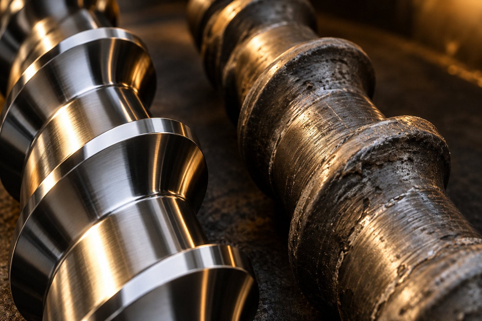
A perfectly optimized screw geometry means nothing if the screw itself erodes after a few thousand hours of production. Every flight clearance you carefully specified widens as metal wears away. Every compression ratio you dialed in for your polymer shifts as channels deepen unevenly from abrasion. The geometry you designed on paper and the geometry actually running inside your barrel diverge a little more with every rotation — and production quality degrades along with it.
That is why screw material selection is not an afterthought you settle at the purchasing stage. It is a core design parameter that determines how long your optimized geometry actually performs as intended.
Screw material selection is a design parameter as critical as channel depth or compression ratio. The best geometry in the world cannot deliver consistent results if the metal underneath it cannot survive the processing environment.
Base Screw Materials and Their Applications
The base steel of a screw provides its structural backbone — the toughness to resist deflection under pressure, the hardness to slow surface erosion, and the thermal stability to hold dimensions at processing temperatures. Different processing demands call for different starting points.
AISI 4140 steel is the workhorse of the industry. As Advanced Heat Treat Corp. notes, 4140 and 4340 are the most common steels for making extruder screws. They offer a solid combination of toughness, machinability, and moderate hardness at an accessible price point. For general-purpose processing of unfilled polyolefins, polystyrene, and other non-abrasive resins, a properly heat-treated and nitrided 4140 screw delivers reliable service life. Its limitation shows up when fillers, reinforcements, or corrosive polymers enter the picture — the iron-rich matrix lacks the hardness to resist abrasive particles and the chemical inertness to withstand corrosive byproducts like HCl from PVC.
Through-hardened tool steels like D2 and CPM series steels step in for moderate to severe abrasion environments. D2 is a high-carbon, high-chromium tool steel that provides significantly better wear resistance than 4140, making it suitable for mineral-filled or moderately glass-reinforced compounds. CPM (Crucible Particle Metallurgy) steels — including CPM 9V and CPM 10V — use a powder metallurgy manufacturing process to achieve a uniform carbide distribution that conventional tool steels cannot match. This translates to superior abrasion resistance and toughness in combination. When you are processing glass-fiber-reinforced nylon or heavily mineral-loaded compounds at high throughput, these steels keep flight dimensions stable far longer than standard alloy steels.
Specialty nitridable steels like Nitralloy 135M (Nit135M) and H-13 hot work tool steel represent the upper tier for demanding applications. Ion/plasma nitriding of Nit135M and H-13 produces surface hardness exceeding 70 HRc equivalent — a level that resists even aggressive abrasive fillers. H-13, originally developed for die-casting tooling, brings excellent hot hardness, meaning it retains its wear resistance at the elevated temperatures encountered during extrusion of engineering thermoplastics.
The selection logic is straightforward: match the base steel's hardness, toughness, and corrosion resistance to the severity of your processing environment. Running unfilled LDPE film? A nitrided 4140 screw will serve you well for years. Compounding 40% glass-filled PA66? You need CPM or Nit135M — anything less will wear out before your first scheduled maintenance window.
Surface Treatments and Coatings for Extended Screw Life
Base steel selection sets the foundation, but surface engineering is where screw wear resistance coating technology truly extends operational life. The principle is simple: apply a harder, more chemically resistant surface layer to the areas that take the most punishment — primarily flight lands, flight tips, and root surfaces in the compression and metering zones.
Nitriding is the most widely used surface treatment for extruder screws. The process diffuses nitrogen atoms into the steel surface at elevated temperatures (typically 950-1070°F), forming hard chromium nitride layers that are thermally stable at extrusion processing temperatures. A nitrided extruder screw gains substantial surface hardness — from around 58 HRc for a nitrided 4140 to over 70 HRc for nitrided Nit135M — while maintaining the tough, ductile core that prevents brittle fracture under torsional loads. Two main variants exist: gas nitriding, which works well for shorter screws, and ion/plasma nitriding, which is better suited for long screws because tall vertical vacuum chambers can treat lengths exceeding 40 feet. Ion/plasma nitriding also allows selective masking — non-wearing surfaces can be protected from treatment, preserving dimensional accuracy where it matters.
Hard chrome plating provides a different kind of protection. Rather than hardening the base steel itself, chrome plating deposits a thin layer of chromium onto the screw surface. Its primary value is corrosion resistance, making it the traditional choice for PVC processing where HCl attack degrades iron-based surfaces. Chrome plating also offers moderate abrasion resistance and a low-friction surface finish. The catch? As Advanced Heat Treat Corp. points out, chromium has a different coefficient of thermal expansion than the underlying steel, and it can exfoliate from the surface at elevated temperatures — a real concern for high-temperature engineering resin processing.
Tungsten carbide coatings and hardfacing address the most extreme abrasion scenarios. Applied through thermal spray, laser cladding, or weld overlay, tungsten carbide creates a screw wear resistance coating with hardness levels that far exceed nitriding alone. This is the go-to protection for processing heavily glass-filled or mineral-filled compounds where abrasive particles grind relentlessly against flight surfaces. Cobalt-based alloys like Stellite and nickel-based alloys like Colmonoy are also used as weld-on hardfacing materials, offering excellent mechanical and anti-corrosive properties — though their adhesion to the base screw material can be comparatively weaker than diffusion-based treatments like nitriding.
Bimetallic screw barrel systems deserve special attention because screw and barrel must be considered as a matched pair. A bimetallic barrel uses a centrifugally cast alloy liner — often containing tungsten carbide particles — bonded to a standard steel outer shell. This liner provides superior wear resistance on the barrel side. Here is the critical point: the screw material and the barrel liner must be metallurgically compatible. As Glycon Corp.'s Jeff Kuhman emphasizes, softer materials have a greater tendency to gall when contacting harder materials. Pairing a soft screw flight hardfacing with an extremely hard bimetallic barrel liner can accelerate adhesive wear on the screw — the harder barrel surface essentially sands down the softer flight tips. Alloys with lower tungsten carbide content may be easier to apply and finish, but they offer less abrasion resistance and have a greater tendency to gall against the hardest barrel linings. Specifying a screw with high hardness that also runs compatibly with your barrel liner material is essential for long component life.
Matching Screw Metallurgy to Processing Demands
Three distinct wear mechanisms attack screws and barrels, and each one responds to different material strategies. Understanding which mechanism dominates your process is the key to proactive screw material selection.
Adhesive wear occurs when metal surfaces — the screw flight land and the barrel interior — briefly contact each other, weld together under extreme local stress, and then fracture apart. Evidence of adhesive wear includes burrs or "rolling over" of the trailing edge of flight lands, scoring on the barrel bore, or missing patches of hardfacing. This type of wear is driven by misalignment, screw deflection from solids wedging, or incompatible screw/barrel metallurgy.
Abrasive wear is the most common mechanism in plastics processing. As pellets are transported and compressed against the barrel wall, the shearing action gradually removes material from flight surfaces and barrel linings. Abrasive wear accelerates dramatically with glass fibers, mineral fillers, flame retardants, or contaminants in regrind. Hard fillers can reduce screw and barrel useful life by 50% or more if components lack adequate protection.
Corrosive wear is the gradual chemical attack on metal surfaces — most commonly experienced when processing PVC or fluoropolymers that release acidic byproducts at processing temperatures. Corrosion damages the surface oxide layer, exposing fresh metal to both chemical and mechanical wear simultaneously. Materials with high iron content are especially vulnerable.
The table below maps common processing scenarios to recommended screw material and coating combinations, giving you a starting framework for matching metallurgy to your specific demands:
| Processing Scenario | Dominant Wear Mechanism | Recommended Screw Material | Surface Treatment / Coating | Barrel Recommendation |
|---|---|---|---|---|
| Unfilled polyolefins (PE, PP) | Mild abrasive | Nitrided 4140 or 4340 steel | Gas or ion/plasma nitriding | Standard nitrided or bimetallic liner |
| Glass-fiber-reinforced compounds (PA-GF, PBT-GF) | Severe abrasive | CPM 9V / CPM 10V or Nit135M | Tungsten carbide hardfacing on flights; nitriding on root | High tungsten carbide bimetallic barrel liner |
| Corrosive PVC processing | Corrosive + mild abrasive | Corrosion-resistant alloy steel | Hard chrome plating or nickel-based coating (Colmonoy) | Nickel-alloy or corrosion-resistant bimetallic liner |
| Mineral-filled compounds (CaCO3, talc, mica) | Moderate to severe abrasive | D2 tool steel or CPM series | Nitriding + tungsten carbide on flight tips | Bimetallic liner with moderate carbide content |
| Abrasive recycled feedstock (regrind with contaminants) | Abrasive + adhesive (tramp metal risk) | CPM 9V or through-hardened tool steel | Tungsten carbide hardfacing; Stellite overlay for high-impact zones | High-wear bimetallic barrel; magnetic trap at feed throat |
| Unfilled engineering resins (PC, PET, ABS) | Mild abrasive + potential corrosive (moisture-related) | Nitrided 4140 or H-13 | Ion/plasma nitriding | Standard nitrided or bimetallic liner |
A few patterns emerge from this table. Unfilled commodity resins are gentle enough that standard nitrided alloy steels deliver acceptable life. The moment you introduce glass fibers, mineral fillers, or corrosive polymers, you need to jump to tool steels, specialized coatings, or both. And recycled feedstocks — increasingly common as sustainability pressures grow — combine unpredictable abrasion from contaminants with occasional tramp metal that can cause catastrophic adhesive wear if not intercepted upstream.
The economics are compelling. A nitrided 4140 screw might cost a fraction of a CPM 9V screw with tungsten carbide hardfacing. But if you are running 30% glass-filled nylon, the cheaper screw may need replacement every few months while the premium screw lasts years. Factor in downtime, changeover labor, lost production, and the quality defects that accumulate as worn clearances degrade melt uniformity — and the higher upfront investment almost always delivers a lower total cost of ownership.
Proactive material selection also means regular monitoring. As industry experts recommend, tracking flight OD measurements over time helps you identify the point of diminishing returns — where incremental wear begins to measurably impact output quality — so you can schedule rebuilds or replacements before unplanned downtime forces your hand.
Screw metallurgy completes the material side of extruder screw design. Combined with the right geometry, zone architecture, mixing elements, and polymer-specific parameters, it forms a fully specified system. But specifying all these elements in harmony — balancing competing requirements across geometry, materials, and process targets — demands a structured approach. That is exactly what a step-by-step design workflow provides.
A Step-by-Step Screw Design Selection Workflow
Knowing every geometry parameter, zone function, mixing principle, and metallurgy option is valuable — but only if you can assemble those pieces into a coherent design decision. And that is exactly the challenge most processing engineers face. You are not short on vocabulary. You are short on a repeatable process that connects polymer requirements to a finished screw specification without relying purely on trial and error.
This extruder screw selection guide lays out a structured workflow that turns scattered knowledge into actionable design steps — and highlights the critical trade-offs you will negotiate along the way.
Step-by-Step Screw Design Selection Process
Whether you are specifying a screw for a new extrusion line or replacing an underperforming one, the custom screw design process follows a logical sequence. Each step builds on the decisions made before it:
- Define the polymer and its thermal/rheological properties. Start with the material. What is its melt temperature range, heat of fusion, shear sensitivity, moisture content, and tendency to degrade? A PVC compound and a glass-filled PA66 demand fundamentally different approaches — and that distinction must be locked in before any geometry discussion begins.
- Establish output targets, melt temperature limits, and quality requirements. What throughput do you need in kg/hr? What is the maximum allowable melt temperature before degradation or property loss? What are your quality benchmarks — gel count, color uniformity, dimensional tolerance? These constraints define the envelope your screw must operate within.
- Select the extrusion platform. Based on the process duty — simple melt pumping versus intensive compounding, single-ingredient versus multi-additive formulations — choose between single-screw and twin-screw. As discussed earlier, this is a platform decision that precedes geometry details.
- Determine baseline geometry. With the polymer and platform settled, establish your starting L/D ratio, compression ratio, feed and metering channel depths. Use the polymer-specific guidance from the previous sections as your reference — HDPE at 3.0-3.5 compression, PVC at 1.3-1.6, and so on. These baselines give you a rational starting point rather than an arbitrary guess.
- Select mixing elements based on dispersive and distributive needs. Does your formulation contain agglomerates that need high-stress breakup? Or pre-dispersed additives that just need spatial redistribution? Choose Maddock mixers, barrier flights, kneading blocks, or toothed elements accordingly — and sequence them to match the melt state at each position along the screw.
- Choose screw material and surface treatment based on the wear environment. Match base steel, nitriding, coatings, and barrel liner compatibility to your processing scenario. Glass fibers demand tungsten carbide. PVC demands corrosion resistance. Unfilled commodity resins need standard nitrided steel. This step protects the geometry you specified in steps four and five from eroding away prematurely.
- Validate the design through simulation or trial runs. Use extrusion simulation software to model melt temperature profiles, pressure development, and residence time distribution before cutting metal. If simulation is not available, structured trial runs with systematic data collection — melt temperature, head pressure, output rate, product quality — provide the feedback needed to confirm or adjust the design.
- Iterate based on performance data. No screw design is perfect on the first attempt. Collect production data, identify the gap between predicted and actual performance, and refine. Screw geometry optimization is an iterative loop, not a one-shot specification.
This eight-step workflow transforms what often feels like guesswork into an engineering process. Each step narrows the design space, and by step seven, you are validating a well-reasoned specification rather than hoping a catalog screw happens to work.
Balancing Critical Design Trade-Offs
Here is the uncomfortable truth about extruder screw design: improving one performance attribute almost always comes at the expense of another. There is no free lunch inside the barrel. Every geometry choice involves screw design trade-offs that must be weighed against your specific priorities.
Consider these interconnected tensions:
- Melting efficiency vs. degradation risk. Increasing the compression ratio accelerates melting by compacting solids more aggressively against the barrel wall. But that same compression raises shear heating and peak melt temperature. For thermally stable HDPE, the trade-off is manageable. For PVC or TPU, it is a dealbreaker.
- Throughput vs. melt quality. Deeper metering channels pump more material per revolution — but the thicker melt layer experiences lower shear rates and less mixing. Output climbs while homogeneity drops. Push output too far, and you start seeing unmelts, temperature variations, and surface defects that downstream equipment cannot correct.
- Mixing intensity vs. residence time. Adding kneading blocks or mixing sections improves additive dispersion and thermal uniformity. But every additional element extends the time material spends at elevated temperature. For heat-sensitive polymers, that extra residence time means degradation, discoloration, or molecular weight loss.
- Sealing efficiency vs. wear rate. Tighter flight clearances reduce backflow leakage and improve pumping efficiency. They also increase localized shear heating at the flight tip and accelerate metal-to-metal wear — especially with abrasive fillers. Over-specifying tight clearances creates a screw that performs beautifully for a few hundred hours, then degrades rapidly as wear opens the gaps beyond useful tolerances.
- Capital cost vs. total cost of ownership. A general-purpose screw built from nitrided 4140 steel costs a fraction of a custom-profiled CPM 10V screw with tungsten carbide hardfacing. But if your process demands the premium specification, the cheaper screw's frequent replacements, lost production during changeovers, and accumulated quality defects from progressive wear will far exceed the upfront savings.
The key insight? These trade-offs cannot be resolved by optimizing any single parameter in isolation. A systems-thinking approach — where compression ratio, channel depths, mixing elements, flight clearances, and screw material are all tuned together against the polymer's requirements and the production's quality targets — is the only path to a robust design. Changing one variable without reassessing its downstream effects is where most screw design problems originate.
When to Partner with Screw Design Specialists
Walk through the workflow above and you will notice something: every step requires specific expertise. Polymer rheology data, simulation capabilities, metallurgical knowledge, and real-world processing experience all converge in screw specification. Many processing companies excel at running extrusion lines and managing production — but do not maintain in-house screw design engineering resources. And that is perfectly reasonable.
The reality is that screw geometry optimization sits at the intersection of polymer science, mechanical engineering, and applied metallurgy. Getting it right demands access to material property databases, computational modeling tools, and — critically — accumulated experience with how specific polymer families behave on specific equipment configurations. A specialist who has designed hundreds of screws for similar applications can shortcut weeks of trial-and-error iteration that a generalist team would need to reach the same result.
This is where working with a dedicated screw design partner adds measurable value. NANHAIYA's custom screw design services, for example, help plastic processing companies match screw geometry, barrel design, material selection, and surface treatment to specific polymers, output targets, and production requirements. That full-system approach — addressing not just the screw profile but also the barrel configuration and wear-resistance strategy as an integrated package — directly mirrors the workflow steps outlined above. Rather than specifying each component independently and hoping the pieces fit, a specialist partner coordinates the entire screw-barrel system to deliver target performance from day one.
You do not need to outsource every screw specification. Simple applications with well-established parameters — unfilled polyolefin film on a standard 24:1 single-screw line, for instance — may need nothing more than a catalog selection and an experienced operator's judgment. But when the application involves tight thermal windows, abrasive fillers, multi-component formulations, or throughput targets that push equipment limits, expert collaboration turns from a nice-to-have into a cost-saving decision. The expense of a properly engineered screw design is a fraction of the cost of lost production, scrapped material, and premature component replacement caused by a poorly matched one.
A sound design workflow produces a screw that meets its targets on day one. But day one is just the beginning. How that screw performs over months and years of production — its impact on energy consumption, product consistency, and maintenance budgets — is where the full return on a well-designed system becomes visible.

Optimizing Screw Design for Energy Efficiency and Production Quality
A screw that hits its melt temperature and throughput targets on startup is a good screw. A screw that sustains those targets while minimizing energy waste, preventing defects, and avoiding unplanned downtime for months or years — that is a strategically valuable asset. The difference between the two comes down to how well the design accounts for long-term operational realities, not just initial performance benchmarks.
Most discussions about extruder screw design stop at geometry and materials. But the real payoff — or penalty — shows up in your utility bills, your scrap rate, and your maintenance schedule long after the screw is installed.
Screw Design and Specific Energy Consumption
Every kilowatt-hour your extruder motor draws gets converted into one of two things: productive work (melting, mixing, and pressurizing polymer) or waste heat that your cooling systems must remove. The ratio between these two outcomes is directly governed by screw geometry.
Research published in Renewable and Sustainable Energy Reviews frames this relationship clearly: the mechanical energy fed into the drive is converted by the screw action on the material to create heat and thus melting. The energy share required for material conveying is relatively smaller, as is the energy supplied by barrel heaters. In other words, the screw is your primary energy conversion device — and its geometry determines how efficiently that conversion occurs.
Specific energy consumption (SEC), measured in kWh/kg, is the metric that captures this efficiency. A well-optimized screw converts more motor energy into productive melting at the barrel wall and less into parasitic shear heating deep within the melt channel. An over-shearing screw does the opposite — it dumps excessive viscous dissipation into the polymer bulk, raising melt temperature beyond what melting requires. You then pay twice: once for the electricity that generated that excess heat, and again for the cooling capacity needed to remove it before the melt reaches the die.
The consequences ripple outward. Over-sheared polymer arrives at the die hotter than intended, which degrades mechanical properties, narrows your downstream cooling window, and can trigger thermal degradation that produces gels, discoloration, or reduced molecular weight. You are simultaneously wasting energy, damaging product quality, and accelerating screw wear from the elevated temperatures and pressures involved. As the same research notes, many commercial polymer producers avoid operating at higher screw speeds precisely because the resulting temperature variation threatens product quality control — even though higher speeds could theoretically improve energy efficiency through reduced polymer viscosity.
Where does screw design optimization fit in? Consider these geometry-driven efficiency levers:
- Compression ratio calibration: A compression ratio matched to your polymer's melting energy requirement delivers complete melting with minimal excess shear. Too much compression wastes energy as heat; too little leaves unmelts that force reprocessing or scrap.
- Barrier screw adoption: Barrier designs maximize solid-bed contact with the barrel wall, improving melting efficiency per unit of screw length. This means the same output can often be achieved at lower screw speeds — reducing both SEC and melt temperature simultaneously.
- Mixing section selection: Distributive mixing elements that homogenize temperature without generating high shear reduce the energy penalty of achieving melt uniformity. Replacing an overly aggressive dispersive mixer with a well-chosen distributive alternative can shave degrees off your melt temperature and watts off your motor draw.
- Flight clearance management: Worn clearances increase leakage flow, forcing the screw to work harder to maintain output. Proactive screw replacement or rebuild at the right wear threshold avoids the gradual SEC creep that accumulates over thousands of hours.
Frame this as both a cost reduction and a sustainability initiative. The European Best Practice Guide for the plastics industry estimates that a 10% reduction in energy consumption across the sector could eliminate 3 megatonnes of CO2 emissions in Europe alone. At the machine level, every fraction of a kWh/kg you shave through better screw design translates directly to lower operating cost and a smaller environmental footprint — compounding over every kilogram of polymer your line processes.
Troubleshooting Common Extrusion Defects Through Screw Geometry
Energy efficiency matters over the long run. But what about the production problem sitting on your line right now? When defects appear in extruded product, the instinct is to adjust barrel temperatures, tweak screw speed, or blame the resin batch. Sometimes those fixes work — temporarily. But if the root cause lives in the screw geometry itself, process adjustments are just masking a design mismatch that will keep resurfacing.
The table below maps common extrusion defects to their likely screw design root causes and the corrective geometry adjustments that address them at the source. Think of it as an extrusion defect troubleshooting guide that looks inside the barrel rather than just at the control panel.
| Defect | Symptoms | Likely Screw Design Root Cause | Corrective Geometry Adjustment |
|---|---|---|---|
| Unmelts | Translucent or opaque particles visible in extrudate; hard spots in product | Insufficient melting capacity — compression ratio too low, transition zone too short, or screw speed exceeding melting flux capability | Increase compression ratio; lengthen transition zone; add barrier flights to maximize solid-bed contact with barrel wall; add Maddock mixer to trap and remelt solids |
| Melt fracture | Spiral distortions, gross surface roughness, or irregular extrudate shape at die exit | Excessive melt temperature or inconsistent melt viscosity from over-shearing in metering zone or mixing sections | Deepen metering channel to reduce shear rate; replace aggressive dispersive mixing elements with lower-intensity alternatives; verify flight clearances are not excessively tight |
| Gels | Small transparent or semi-transparent specks; fish-eyes in film products | Incomplete mixing leaving high-molecular-weight fractions or crosslinked regions undispersed; dead spots in screw channel where material stagnates and degrades | Add or upgrade dispersive mixing section (barrier flight or Maddock mixer); eliminate channel dead zones; verify screw profile has no stagnation points |
| Black specks / degradation | Dark discolored particles; brown or black streaks in product | Excessive residence time from overly long screw or low-fill zones; over-shearing in tight clearances or aggressive kneading blocks; stagnant material in worn or damaged screw channels | Reduce L/D if possible; replace worn screw to eliminate stagnation pockets; reduce kneading block intensity; ensure no reverse elements create unnecessary melt seals |
| Output surging | Periodic fluctuation in extrudate dimensions; pulsating die pressure | Inconsistent solids conveying from feed zone design mismatch; solid bed breakup in transition zone; insufficient metering zone length to dampen pressure fluctuations | Optimize feed zone depth for resin bulk density; consider grooved feed barrel for pressure-independent conveying; lengthen metering zone; add barrier section to stabilize melting |
| Poor color dispersion | Visible color streaks; uneven tinting; color intensity variation across product cross-section | Inadequate distributive mixing — no flow-splitting elements to redistribute colorant spatially across the melt stream | Add distributive mixing elements (pineapple mixer, slotted flights, or forward-stagger kneading blocks); position mixing section after melting is complete for maximum effectiveness |
| Excessive melt temperature | Product warping, degradation, or dimensional instability; cooling system overwhelmed | Over-compression, excessively tight flight clearances, or aggressive mixing elements generating more viscous dissipation than the polymer requires | Reduce compression ratio; widen flight clearances slightly; replace high-shear mixing elements with lower-energy alternatives; consider barrier screw to achieve equivalent melting at lower shear input |
Notice that most corrective actions involve changing the screw itself — not just dialing process settings up or down. Temperature adjustments and speed changes can compensate for a geometry mismatch in the short term, but they introduce their own side effects: higher energy consumption, reduced throughput, or shifted quality attributes elsewhere in the product. Fixing the screw geometry fixes the root cause and eliminates the need for compensatory process compromises.
Investing in the Right Screw Design for Long-Term Success
If one takeaway runs through every section of this article, it is this: extruder screw design is not a one-time purchase decision. It is an ongoing optimization opportunity that evolves as your materials change, your product specifications tighten, your throughput targets increase, and your sustainability commitments deepen.
A screw specified for yesterday's resin grade may underperform with today's reformulated compound. A geometry that delivered acceptable quality at 200 kg/hr may produce unmelts at 300 kg/hr. A surface treatment that lasted three years on unfilled PP may wear through in six months when you add 20% calcium carbonate to the formulation. Every shift in material, output, or product requirement is an invitation to revisit the screw-barrel system and ask whether the current configuration still represents the best engineering answer.
Processors who treat screw design as a strategic investment — rather than a commodity line item on a maintenance budget — consistently achieve lower specific energy consumption, fewer quality-related stoppages, longer intervals between screw replacements, and more stable production economics. The upfront engineering cost of a properly matched screw-barrel system is recovered many times over through reduced scrap, lower energy bills, and fewer hours of unplanned downtime.
For operations looking to apply the principles discussed throughout this article with expert guidance, working with an experienced screw design partner ensures that screw geometry, barrel configuration, material choices, and surface treatments are continuously aligned with evolving production requirements. NANHAIYA's custom screw design services exemplify this full-system approach — helping processors reduce screw wear, improve melt quality, and lower total cost of ownership by coordinating every element of the screw-barrel system against specific polymers, output targets, and application demands. Rather than replacing screws reactively when defects become unmanageable, a proactive partnership keeps the entire system optimized as conditions change.
Treat your extruder screw as a strategic production asset, not a commodity replacement part. The geometry inside your barrel determines your energy cost per kilogram, your defect rate per shift, and your maintenance spend per year — invest in it accordingly.
Frequently Asked Questions About Extruder Screw Design
1. What is the most important parameter in extruder screw design?
No single parameter dominates in isolation — extruder screw design is a system of interdependent variables. However, the compression ratio (feed channel depth divided by metering channel depth) is often the first critical decision because it directly controls the rate of volume reduction, shear intensity, and pressure applied to the polymer during melting. A mismatched compression ratio causes cascading problems: too high and you risk thermal degradation in heat-sensitive resins like PVC; too low and you get incomplete melting that shows up as unmelts and gels in the final product. The compression ratio must always be evaluated alongside L/D ratio, channel depths, and the specific polymer's thermal and rheological properties to produce a balanced, effective screw profile.
2. How do I choose between a single-screw and twin-screw extruder?
The decision hinges on your process duty rather than throughput alone. Single-screw extruders excel at continuous melt pumping of pre-compounded materials — they are simpler, less expensive, and generate excellent die pressure for applications like film, pipe, sheet, and profile extrusion. Twin-screw extruders, especially co-rotating intermeshing designs, are built for intensive mixing, multi-ingredient compounding, devolatilization, and reactive processing. Their modular screw elements can be rearranged to create custom mixing profiles. If your material is already formulated and just needs melting and shaping, single-screw is typically the practical choice. If you need to blend fillers, disperse pigments, remove volatiles, or incorporate multiple additives, a twin-screw platform justifies its higher cost through superior mixing flexibility.
3. Why does PVC require a different screw design than polyolefins?
PVC has an extremely narrow processing window and degrades rapidly when exposed to excessive heat or shear, releasing corrosive hydrochloric acid. This thermal sensitivity demands low-compression screw designs (typically 1.3 to 1.6 compression ratio) with shallow channels, gentle transition zones, and shorter L/D ratios to minimize residence time. Barrier flights are generally avoided because their tight clearances generate localized shear that triggers degradation. In contrast, polyolefins like HDPE are semi-crystalline with high heats of fusion and relatively broad thermal stability, allowing compression ratios of 3.0 to 3.5 and aggressive barrier designs. Additionally, PVC screws require corrosion-resistant coatings such as hard chrome plating to withstand HCl attack — a consideration that does not apply to polyolefin processing.
4. What screw materials and coatings are best for processing glass-fiber-filled compounds?
Glass fibers are harder than standard tool steels and cause severe abrasive wear on screw flights and barrel walls. For glass-fiber-reinforced compounds, premium base materials like CPM 9V, CPM 10V, or Nitralloy 135M are recommended over standard 4140 alloy steel. Tungsten carbide hardfacing applied to flight lands and tips provides the hardest available surface protection against abrasive particles, while the screw root can be ion/plasma nitrided for additional hardness. The barrel should use a high tungsten carbide content bimetallic liner matched to the screw's hardness — mismatched hardness between screw and barrel can accelerate adhesive wear on the softer component. Partners like NANHAIYA offer integrated screw-barrel material matching as part of their custom design services to ensure both components work together for maximum service life.
5. How does screw design affect energy efficiency in extrusion?
The extruder screw is the primary energy conversion device in any extrusion line — it transforms motor-driven mechanical energy into the thermal and pressure energy needed to melt, mix, and pump polymer. Screw geometry directly determines specific energy consumption (kWh/kg). An over-compressing or over-shearing screw dumps excess viscous heat into the melt, forcing cooling systems to remove energy you already paid to generate. A well-optimized screw — with compression ratio calibrated to the polymer's melting requirements, barrier flights to maximize melting efficiency, and appropriately selected mixing elements — converts more input energy into productive work and less into waste heat. This reduces electricity costs, lowers melt temperatures for better product properties, and decreases cooling demand downstream.
Written by
Nanhaiya Technical Team
Zhoushan Nanhaiya Plastic Machinery Co., Ltd.
The Nanhaiya technical team supports screw and barrel manufacturing projects through application review, technical communication, custom manufacturing coordination, and production and quality control.
Discuss Your Application
Related Articles
More insights on screw barrel technology and plastics processing.
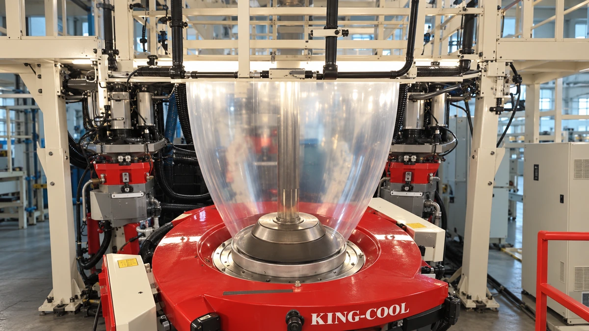
Blown Film Problems Decoded: What Your Bubble Is Telling You
Oct 23, 2026
Solve blown film problems from resin to roll. Learn to identify gels, gauge variation, bubble instability, die defects, and downstream failures with actionable fixes.
Read Article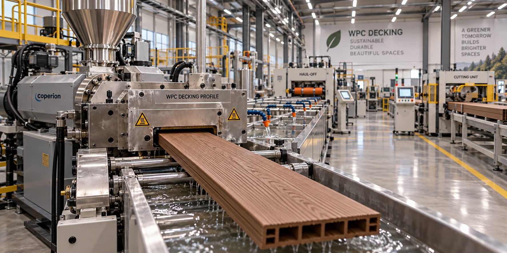
WPC Decking Extrusion Line Decoded: From Raw Resin To Finished Board
Oct 23, 2026
Learn how a WPC decking extrusion line works — from raw material compounding and extruder selection to process parameters, troubleshooting defects, and line layout planning.
Read Article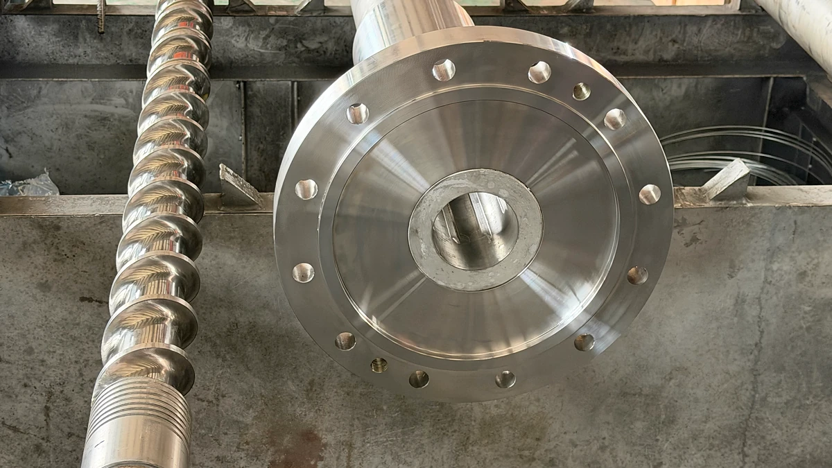
Single Screw Extruder Barrel Wear: Spot It, Measure It, Stop It
Oct 23, 2026
Learn how to spot, measure, and stop single screw extruder barrel wear. Zone-by-zone analysis, wear mechanisms, diagnostic symptoms, and repair vs. replace guidance.
Read ArticleLooking for something else?
Search by material, symptom or product and jump straight to the relevant page.
These are navigation suggestions based on keyword matching — not a quotation, not a delivery commitment, and not a substitute for engineering review. Final specification is confirmed by our engineers against your drawings and processed material.
Need help with screw barrel selection?
Share your machine model, processed material and application. Our team can help with pricing and technical support.