

What Plastic Extruder Screw Barrel Service Actually Involves
Imagine your extruder slowly losing output over weeks, melt quality drifting just enough to raise scrap rates, and energy costs creeping upward with no obvious cause. The culprit is often hiding in plain sight: worn screw and barrel components quietly degrading process control from the inside out.
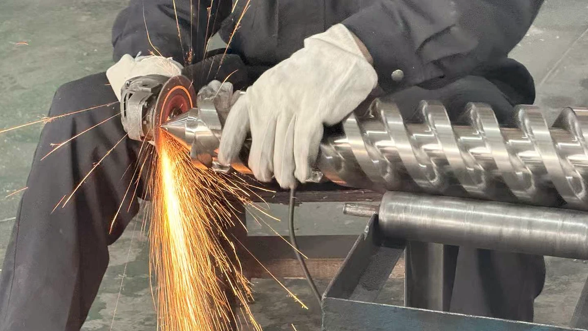
Plastic extruder screw barrel service is the full range of inspection, reconditioning, repair, and replacement activities performed on worn screw and barrel assemblies to restore them to original or improved performance specifications.
This service category covers both continuous extrusion lines - where extruder barrels and screws run for thousands of hours shaping profiles, film, sheet, and pipe - and injection molding machines, where the plasticating unit cycles repeatedly under high pressure to fill molds. The wear mechanisms differ between these two contexts, but the core service discipline remains the same: measure, diagnose, and match the right fix to the specific type and severity of wear.
Defining Screw Barrel Service in Plastics Processing
Think of screw barrel service not as emergency repair but as a planned lifecycle discipline. It begins at initial commissioning, when baseline dimensions are recorded for the new screw and barrel. From there, periodic inspections track how clearances change over operating hours. Reconditioning techniques - hard chroming, hardfacing, re-nitriding, or bimetallic relining - extend useful life when wear is caught early. Replacement becomes the right call when damage exceeds what reconditioning can recover. Each stage feeds data into the next, turning reactive breakdowns into predictable maintenance events.
Why Screw and Barrel Condition Drives Process Performance
The screw and barrel are where raw polymer becomes a controlled melt. As Glycon Corp.'s Jeff Kuhman explains, clearances between the screw flight outside diameter and the barrel bore are typically minimal - around 0.001 inch per side, per inch of diameter - to achieve proper heat transfer and shear rate. As soon as the screw begins rotating, wear starts. Even small increases in that clearance reduce pumping efficiency, allow molten polymer to leak backward, and force operators to compensate with higher speeds, adjusted temperatures, or increased back pressure.
These compensations mask the real problem temporarily. Over time, though, extruder screw wear issues compound: output consistency drops, melt temperature stability suffers, energy consumption rises, and part quality becomes harder to hold. The extruder feed barrel geometry erodes, weakening solids conveying right where the process begins. Understanding this progression - and knowing when each service intervention makes sense - is what separates a well-managed plasticating unit from one that runs to failure.
The real question isn't whether your screw and barrel are wearing. They are. The question is where that wear concentrates, how fast it's progressing, and which service response will restore performance most effectively.
How Wear Progresses Across Extruder Screw and Barrel Zones
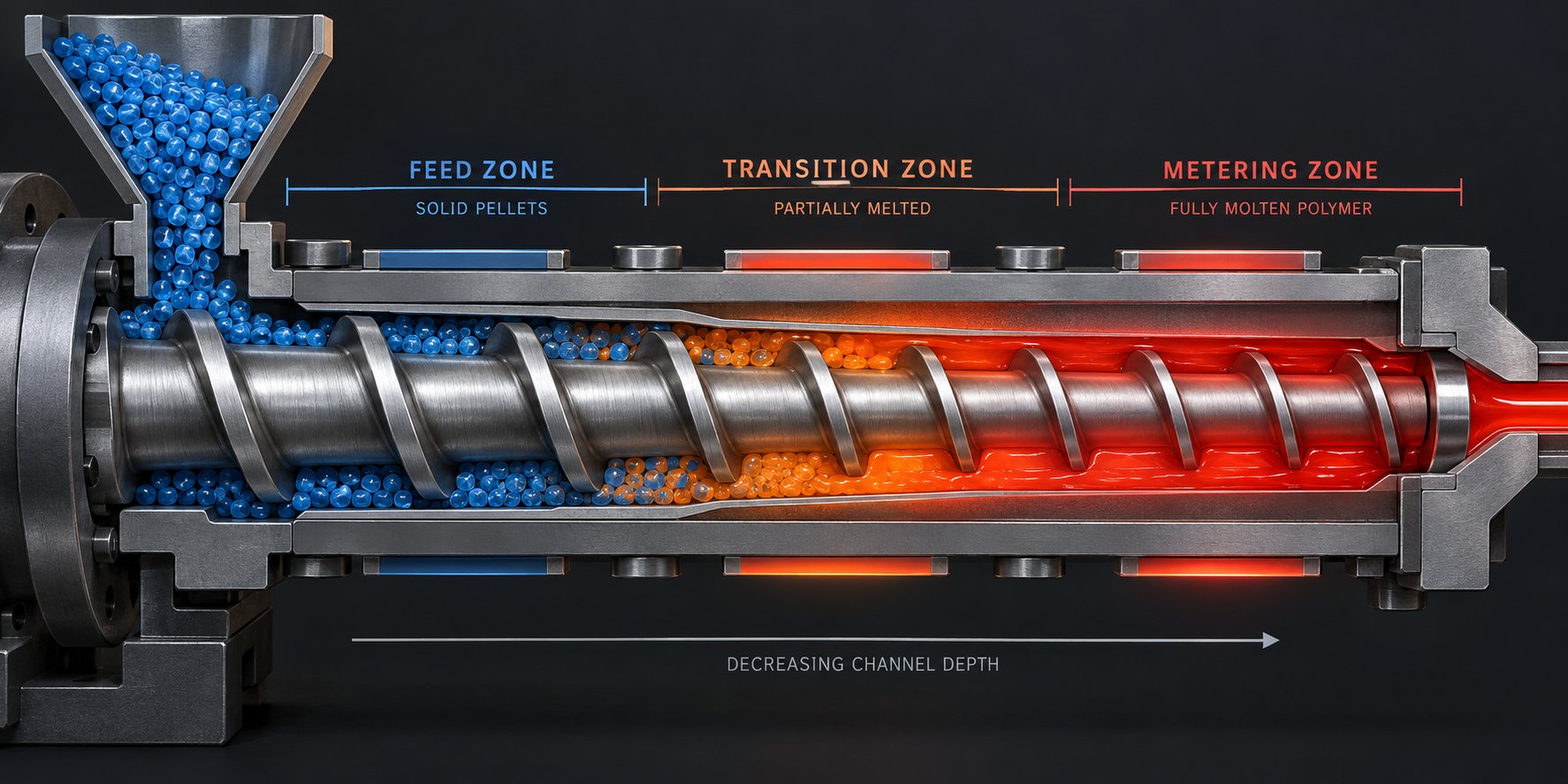
Every screw has three functionally distinct zones, and each one wears in its own way for its own reasons. Lumping all wear together as a single problem leads to mismatched service decisions - you might hard-chrome a section that actually needs hardfacing, or replace a full screw when only one zone has degraded past tolerance. Understanding zone-by-zone wear patterns is the foundation of choosing the right fix at the right time.
Feed Zone Wear Patterns and Causes
The feed zone is where solid pellets first enter the extrusion barrel and begin moving forward. At this stage, polymer is still cold, hard, and unmelted. You'll find that the dominant wear mechanism here is straightforward abrasion: solid granules scrape against the flight lands and the barrel bore with every screw rotation. If the resin contains glass fiber, mineral filler, or any hard contaminant, that abrasion intensifies significantly.
Picture thousands of tiny, sharp-edged particles being dragged under pressure between two metal surfaces. The flight lands - particularly their leading edges - erode as the forwarding side of each flight pushes against the solid bed. The barrel bore in this region also loses material, though typically at a slower rate because it presents a larger, stationary contact area. As Stephen Surley of SpiraMelt Technologies notes, when processing abrasive fillers, severe wear can appear in the feed section as pressure builds on the forwarding side of the flight, with limited lubrication from the unmelted pellets.
The extruder feed barrel geometry in this region controls how efficiently solids are conveyed downstream. As the flight OD wears down and the barrel bore opens up, the screw's ability to grip and push solid pellets forward weakens. The result? Reduced conveying efficiency, inconsistent feeding, and a cascading loss of throughput that operators often try to fix by raising screw speed - which only accelerates the wear cycle.
Transition and Metering Zone Degradation
Move downstream into the transition (compression) zone, and the wear environment changes dramatically. Here, polymer is partially melting under increasing shear and pressure. The extruder screw flights encounter a mix of solid fragments and viscous melt, creating a combination of abrasive and adhesive wear. Solid particles still gouge metal surfaces, but the partially molten polymer also creates friction-welding-like conditions where metal transfers between screw and barrel surfaces at a microscopic level.
This zone typically experiences the highest pressures and temperatures in the system. Abrasion testing across many industries confirms that increased pressure and temperature leads to increased friction, which is why the transition section and the last few turns of the metering section are where the bulk of OD wear concentrates empirically - a pattern confirmed after inspecting and rebuilding thousands of screws.
The metering zone, where polymer is fully molten, introduces yet another wear driver: chemical corrosion. Fully molten resin at elevated temperatures can attack metal surfaces, especially with chemically aggressive polymers like PVC, which generates hydrochloric acid during processing. In this zone, adhesive and corrosive wear work together. Root wear becomes most severe on the forwarding side of the flights, and degraded material can accumulate in pockets created by that erosion - a common source of black specks and contamination in the final product.
| Zone | Primary Wear Mechanism | Common Symptoms | Typical Service Needed |
|---|---|---|---|
| Feed | Abrasive wear from solid pellets, fillers, and contaminants | Reduced solids conveying, inconsistent feed rate, lower throughput | Hardfacing flight lands (tungsten carbide for filled resins), barrel bore honing or relining |
| Transition (Compression) | Combined abrasive and adhesive wear under high shear and pressure | Unmelted particles in output, pressure surging, rising melt temperature | Flight rebuild with stellite or tungsten carbide overlay, bore restoration |
| Metering | Adhesive and corrosive wear from molten polymer at elevated temperatures | Output loss, melt temperature instability, black specks, degraded material | Hard chrome plating (light wear), hardfacing (moderate wear), corrosion-resistant coatings, re-nitriding |
Why Barrel Wear Follows a Different Pattern Than Screw Wear
Here's a detail that trips up many maintenance teams: the barrel and screw don't wear at the same rate or in the same pattern, even though they operate as a matched pair. The extrusion barrel is stationary, so its bore tends to wear more uniformly along its length within any given zone. Localized hot spots, feed-throat erosion, or corrosive attack at vent sections can create exceptions, but the overall pattern is relatively even compared to the screw.
The screw, on the other hand, concentrates wear on specific features. Flight OD erosion is most severe on the leading edges and the outermost diameter, where direct contact pressure is highest. Root wear - the erosion of the channel floor - is heaviest on the forwarding side of each flight, as described earlier. Mixing sections and barrier flights also degrade because their undercut geometry forces resin to flow over the flight tips, accelerating local erosion. As these mixing designs wear, dispersion quality drops and barrier designs can lose melting capacity.
The practical consequence of this mismatch is the growing clearance between screw flight OD and barrel bore. That clearance is the single most important functional measurement in any plastic extruder screw barrel service evaluation. When it opens beyond acceptable limits, molten polymer leaks backward over the flights instead of being pushed forward - a phenomenon called leakage flow. More viscous resins tolerate slightly larger clearances before output suffers noticeably, while low-viscosity materials show performance losses much sooner under the same conditions.
This is why service decisions should never treat the screw and barrel as independent components. A freshly rebuilt screw installed into a badly worn barrel - or a new barrel paired with an eroded screw - still leaves excessive clearance and shortens the life of whichever part is new. Effective injection mold repair and extrusion service programs evaluate both components together, measuring them at corresponding axial positions to build a complete wear picture before committing to any reconditioning or replacement path.
Knowing where wear concentrates and why it differs between zones is only half the picture. The next challenge is connecting what you see on the production floor - output drops, pressure swings, melt quality problems - back to a specific wear pattern hiding inside the machine.
Connecting Extrusion Problems to Screw and Barrel Wear
You know something is off. Output numbers are slipping, the melt doesn't look quite right, and operators keep nudging temperatures and speeds to hold things together. But which of these symptoms actually point to a worn plastic extruder screw or barrel - and which are caused by something else entirely?
A useful diagnostic principle from the BLOOM Engineering team cuts through most of the guesswork: did the problem appear suddenly, or creep up over months? Sudden changes usually trace to material issues, temperature hardware, or contamination. Gradual onset - where nothing changed but performance got worse - almost always points to wear. That single question narrows the field dramatically before you even pull the screw.
Output Loss and Pressure Instability as Wear Indicators
When screw flight OD erodes and the barrel bore opens up, the clearance between them widens. That widening gap creates a direct path for molten polymer to leak backward over the flights instead of being pushed forward - a phenomenon engineers call leakage flow. The result is a measurable drop in net forward output, even though the extrusion screw is turning at the same RPM it always has.
This output loss doesn't happen overnight. It develops across weeks and months, which is why it's so easy to miss. Operators often compensate by increasing screw speed, which temporarily recovers throughput but also raises shear heating, pushes melt temperatures higher, and accelerates the very wear that caused the drop in the first place. As Jeff Kuhman of Glycon Corp. describes, these incremental adjustments often use more energy and affect part quality - but the changes are small enough that they go unnoticed until they dramatically impact productivity.
Pressure instability tells a different part of the story. Surging - rhythmic fluctuation in die pressure and extrudate dimensions - frequently originates in the feed zone. When the flight lands in that section wear down, solids conveying becomes inconsistent. The barrel extruder assembly can no longer grip and push pellets forward at a steady rate, so the melt stream arrives at the die in uneven pulses. You'll see this as periodic thickness variation in film or sheet, or as weight inconsistency in profile extrusion.
Energy consumption ties into both issues. A worn screw works harder to maintain the same output because pumping efficiency has dropped. Drive load (measured in amps or kilowatts) may actually decrease if output falls faster than the screw can compensate, or it may climb if operators push speed higher. Either way, the energy-per-kilogram-of-output ratio rises - a clear signal that something inside the plasticating unit is costing you money.
Melt Quality Problems Traced to Component Wear
Output quantity is one thing; melt quality is another. And sometimes the quality symptoms are more revealing than the throughput numbers.
Consider poor melt homogeneity - unmelted particles showing up in the extrudate, inconsistent color dispersion, or visible gels. These often point to a worn compression zone. As the transition section geometry degrades, the channel depth profile changes and the screw can no longer generate adequate shear to fully melt and mix the polymer. A general-purpose screw that once performed well may now pass unmelted fragments into the metering section because the compression ratio has effectively changed due to wear.
Black specks and degraded material are a separate - and often more alarming - symptom. When screw root wear or barrel bore irregularities create recessed pockets or dead spots, resin hangs up in those areas and thermally degrades over time. Eventually, pieces of that degraded material break loose and appear in the product as dark specks, streaks, or carbonized particles. The BLOOM troubleshooting reference highlights a frustrating pattern: purging clears the specks temporarily, but they return because the carbon layer is bonded to worn or pitted screw and barrel surfaces. Purging removes only loose material, not the root cause.
Here's a practical diagnostic checklist that maps observable production symptoms to their probable wear-related causes:
- Gradual output decline at constant screw RPM - Increased screw-to-barrel clearance allowing leakage flow, reducing net forward pumping
- Surging or pulsing extrudate dimensions - Worn feed zone flights causing inconsistent solids conveying into the compression section
- Rising melt temperature without barrel setpoint changes - Higher screw speed compensating for lost efficiency, generating excess shear heat
- Unmelted particles or gels in the product - Worn compression zone geometry no longer generating adequate shear for complete melting
- Inconsistent color or additive dispersion - Degraded mixing section geometry reducing distributive mixing capability
- Black specks that return after purging - Dead spots from worn screw root or barrel bore pitting trapping and degrading resin
- Increased energy consumption per unit of output - Screw working harder to compensate for reduced pumping efficiency across all zones
- Wider shot-to-shot variation (injection molding) - Check ring and barrel bore wear allowing inconsistent melt delivery during injection
Not every symptom on this list automatically means your screw or barrel needs service. Temperature hardware failures, material moisture issues, and feed system problems can mimic some of these signs. But when multiple symptoms appear together - especially with gradual onset - component wear moves to the top of the suspect list.
When Process Adjustments Can No Longer Compensate
Here's the trap almost every processor falls into at some point. A slight output drop appears, so an operator bumps screw speed up a few RPM. Melt looks a little uneven, so barrel zone temperatures go up five degrees. Back pressure gets a small increase to improve mixing. Each adjustment is minor, each one seems justified, and each one works - for a while.
The problem is that every one of these tweaks is treating the symptom, not the cause. And the cause - progressive wear of the plastic extruder screw and barrel - keeps advancing regardless of what the controller setpoints say. As Kuhman explains in his analysis of diminishing returns, these incremental changes eventually reach a point where no further adjustment can maintain acceptable quality or output. He calls this the "point of diminishing benefit" - the limit where machine adjustments can no longer minimize any reduction in productivity or quality.
Several warning signs indicate you've crossed that threshold or are approaching it rapidly:
- Screw speed is significantly higher than the original process setup required for the same output
- Barrel temperatures have been raised across multiple zones to compensate for poor melting
- Back pressure is elevated well beyond the original process window
- Cycle times have stretched (injection molding) or line speed has dropped (extrusion) despite process adjustments
- Scrap rates are climbing even though operators are actively managing process parameters
When you find yourself stacking adjustments on top of adjustments, the machine is telling you that the screw and barrel geometry has drifted too far from its design intent. Process parameters can compensate for a certain range of wear, but they cannot restore flight dimensions, rebuild compression ratios, or close up a worn barrel bore. At that stage, the only real solution is pulling the components, measuring the actual wear, and determining whether reconditioning or replacement is the right path forward.
That measurement step - knowing exactly how much wear exists and where it's concentrated - requires specific tools, techniques, and interpretation skills that turn subjective guesswork into objective service decisions.
Wear Measurement Methods and Acceptable Tolerances
Suspecting wear is one thing. Proving it - with numbers precise enough to guide a repair-or-replace decision - is something else entirely. Without accurate dimensional data, you're guessing at the service your screw extruder components actually need. And guessing gets expensive fast, whether it leads to premature replacement of parts with life left in them or to reconditioning work on components already past saving.
Proper measurement transforms a subjective hunch into an objective blueprint for action. Here's how experienced service teams and maintenance departments do it.
Tools and Techniques for Measuring Barrel Bore Wear
The barrel bore is a deep, enclosed cylinder, which makes measuring it more challenging than checking an external dimension. Several instrument types exist, and they vary significantly in accuracy and practicality.
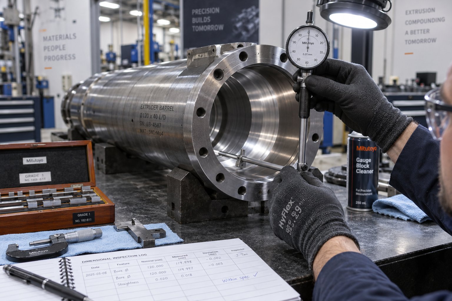
Dial bore gauges are the industry standard for barrel inspection. These indicator-type instruments use two diametrically opposed measuring points - one fixed and one moving - plus a spring-loaded centralizing shoe that seats the gauge on the bore's true diameter. As Services for Plastics describes, this three-point contact design allows the gauge to self-center in the bore, removing much of the operator-feel dependency that plagues other methods. A quality dial bore gauge reads in 0.0005-inch graduations, enough resolution to detect the small clearance changes that matter in plasticating barrels. Setup takes roughly five minutes, and a full-length inspection with recorded data typically finishes in under an hour regardless of barrel size.
Telescoping bore gauges, while common in general machine shops, fall short for barrel work. They require the operator to lock the gauge at a size slightly larger than the bore, insert it at an angle, and then gently align it radially - a technique that depends heavily on the user developing the right "feel." Repeatable accuracy suffers, and these gauges can only measure one spot at a time. They cannot reveal the continuous wear patterns that a full-length measurement protocol exposes.
Air gauges (pneumatic bore gauges) offer a non-contact alternative. They measure bore diameter by sensing changes in air pressure or flow rate as a calibrated plug is moved through the barrel. Air gauges excel at detecting very small dimensional changes and are less sensitive to surface roughness, but they require careful calibration and are less commonly found outside dedicated service shops.
Laser-based measurement systems represent the newest approach. These create a continuous internal bore profile rather than point-by-point readings, mapping the entire barrel length in a single pass. The resulting data reveals taper, ovality, and localized wear pockets with high resolution. While the equipment cost is significant, the speed and completeness of the data make laser profiling increasingly attractive for high-volume service operations.
Regardless of which tool you choose, the measurement protocol matters as much as the instrument itself. Standard practice calls for taking bore readings at fixed intervals along the barrel length - typically every two to four bore diameters of distance. At each station, readings are recorded at multiple clock positions (commonly 0, 90, 180, and 270 degrees) to detect ovality, which indicates uneven wear caused by screw deflection or barrel misalignment. Every reading is compared against the original nominal bore diameter, which for plasticating barrels is typically the nominal screw diameter with a tolerance of 0.001 inch oversize.
One important procedural detail: the barrel must be clean of all residual plastic and cooled to ambient temperature before measuring. Bore readings taken at elevated processing temperatures will be skewed by thermal expansion unless corrected for the material's linear coefficient of thermal expansion - a calculation step that introduces unnecessary error when it can be avoided simply by letting the barrel cool.
Measuring Screw Flight and Root Diameter Wear
Unlike the barrel bore, screw surfaces are fully accessible once the screw is pulled from the machine. This makes measurement physically simpler but no less methodical.
Flight outside diameter (OD) is the most critical screw dimension because it directly determines the clearance gap with the barrel bore. Outside micrometers are the standard tool here, measuring the flight tip diameter at multiple points along the screw length. Go/no-go gauges offer a quicker pass-fail check - particularly useful on the production floor when time is limited - but they don't provide the numerical wear data needed for trending or service decisions. For injection molding screws and barrels, where the plasticating screw may be shorter but cycles under higher pressures, checking flight OD at closely spaced intervals helps catch localized hot spots of wear that a few spot measurements might miss.
Root diameter - the depth of the screw channel - is checked with depth micrometers or profile gauges. Root wear changes the effective channel depth, which alters the compression ratio and the shear the screw imparts to the polymer. If the root erodes unevenly, dead spots form where resin hangs up and degrades - one of the sources of black specks discussed earlier.
Beyond these two primary dimensions, a thorough inspection also evaluates:
- Flight width - narrowing flights indicate leading-edge erosion that reduces the screw's sealing and conveying ability
- Flight straightness - warped or spiraling flights suggest thermal damage or mechanical deflection during operation
- Leading-edge sharpness - rounded or undercut edges reduce the screw's ability to wipe the barrel wall and convey solids efficiently
- Mixing section geometry - worn undercuts, pins, or barrier flights that have lost their original clearance profiles
Each of these features should be measured or visually assessed at consistent axial positions so the data can be compared with previous inspections and with readings from the corresponding barrel bore locations.
Interpreting Measurements and Establishing Service Thresholds
Raw numbers on a measurement sheet don't mean much without context. A 0.010-inch clearance per side might be perfectly acceptable on a large-diameter screw extruder but could signal severe wear on a small-diameter machine. Interpretation depends on several factors working together: original nominal dimensions, screw diameter, the resin being processed, and how critical the application's quality requirements are.
The general rule of thumb for new flight clearance is the nominal screw diameter divided by 1000, per side. For example, a 3.5-inch extruder typically starts life with about 0.004 inch of clearance per side, yielding a flight OD of approximately 3.492 inches. Any clearance beyond that initial value is attributable to wear.
When should you act? Industry experience points to several decision tiers, though the exact thresholds depend on application severity. Noncritical applications like corrugated pipe can tolerate far more wear than precision medical extrusion, where even modest clearance increases affect product consistency. A practical framework from Mark Spalding and Tim Womer's analysis anchors the decision around multiples of the original new clearance:
| Wear Severity Category | Clearance Condition | Typical Process Impact | Recommended Action |
|---|---|---|---|
| Normal operating range | Up to 2x original new clearance | Minimal impact on output and melt quality; no operator compensation needed | Continue monitoring; record data for trend analysis |
| Service recommended | 2x to 4x original new clearance | Measurable output loss, rising discharge temperatures, early signs of melt quality drift; operators adjusting parameters to compensate | Schedule reconditioning (hardfacing, hard chrome, re-nitriding) or plan replacement based on cost analysis |
| Replacement required | Beyond 4x original new clearance, or hard facing completely worn through | Significant rate reduction required to maintain quality; process adjustments can no longer compensate; profitability and capacity declining | Replace screw immediately; measure barrel bore to determine if relining or barrel replacement is also needed |
Keep in mind that these tiers are guidelines, not absolute rules. A critical-duty process such as medical applications may warrant screw replacement after clearance reaches just 2x the new value, while a less demanding application can run productively well beyond 4x. The best approach combines measurement data with economic analysis: at what point does the cost of lost output, increased scrap, and higher energy consumption exceed the cost of service or replacement?
Two additional considerations matter when interpreting barrel data specifically. First, an iron-based bimetallic barrel liner is approximately 0.060-inch thick when finished, and a barrel with this liner typically lasts about three times the service life of a screw. Second, if bore measurements reveal ovality at specific axial positions, the cause may be barrel misalignment or screw deflection rather than uniform wear - a diagnostic clue that points toward mechanical correction rather than relining.
As part of any quality system - whether ISO 9001 or similar - periodic bore measurement is often a documented requirement. Maintaining records over time builds a wear history that allows you to project component life and plan service intervals proactively rather than reactively.
With precise measurements in hand and wear severity classified, the real decision begins: which reconditioning technique matches the type and degree of damage your components have sustained? Hard chroming, hardfacing, re-nitriding, and bimetallic relining each have specific strengths and limitations that determine when they're the right choice - and when they're a waste of money.
Service Techniques from Hard Chroming to Bimetallic Relining
Measurement data tells you how much material is gone. The next question is how to put it back - or whether putting it back even makes sense. Each reconditioning technique in the plastic extruder screw barrel service toolkit has a specific sweet spot: a range of wear severity, a compatible set of base materials, and a realistic expectation of how long the repair will last. Apply the wrong technique to the wrong problem, and you've spent money without solving anything. Match it correctly, and you can restore extruder screws and barrels to performance levels that rival - or sometimes exceed - their original condition.
Hard Chrome Plating and Its Limitations
Hard chrome plating is the most widely used and least expensive surface treatment for screw reconditioning, yet its capabilities are frequently overstated. The process works by electrodepositing industrial chromium onto the screw surface in a carefully controlled bath. Unlike decorative chrome on a car bumper, hard chrome reaches 65-69 Rc hardness - equal to the hardest tool steels - and provides a corrosion-resistant surface with exceptional lubricity.
A typical hard chrome layer is only about 0.001 inch thick. That thinness is both the technique's greatest advantage and its most significant limitation. On a lightly worn screw, that thousandth of an inch restores dimensions without meaningfully altering flight geometry, channel depth, or any other critical profile. The coating's low coefficient of friction - less than one-quarter that of polished steel - actually improves solids conveying in the feed section by reducing the drag between polymer pellets and the screw channel. It also makes cleaning dramatically easier, since degraded polymer releases from a polished chrome surface far more readily than from bare steel.
When does chrome plating fall short? Three situations expose its limits:
- Heavy dimensional loss: Chrome cannot be built up in thick layers without compromising adhesion. With a bond strength of approximately 6,000 psi, the coating holds well on lightly worn surfaces, but it cannot bridge deep wear grooves or rebuild flight lands that have lost significant material. If your screw extruder flights are visibly rounded or undercut, chrome plating alone won't restore the geometry needed for proper sealing and conveying.
- Flight tip surfaces: The contact stress between flight OD and barrel bore routinely exceeds the chrome layer's bond strength. For this reason, screw flights are almost always masked off during the plating process. Chrome protects the channel surfaces and root area, but the flight tips - the very surfaces that wear fastest in abrasive environments - remain uncoated.
- Corrosive acid environments: Hard chrome inherently contains micro-cracks invisible to the naked eye. Acids generated by thermally degrading polymers, especially PVC, can seep through these cracks and attack the bond layer from underneath. The fix is applying multiple thin chrome layers (double or triple chrome) so the crack patterns in successive layers don't align, creating a more impervious barrier. This multi-layer treatment is standard for rigid PVC processing equipment but adds cost and processing time.
Even with these constraints, chrome plating remains a cost-effective first line of defense. It adds only about 10% to the cost of a typical screw, prevents rust during storage and shipping, and extends the useful life of lightly worn components significantly. For many processors running neat commodity resins at moderate throughputs, chrome plating is all the protection they'll ever need on the screw's channel and root surfaces.
Hardfacing with Stellite and Tungsten Carbide
When wear goes beyond what a thin chrome layer can address - particularly on flight lands and tips where chrome cannot be applied - hardfacing enters the picture. This is where extruder services move from surface coating into actual material rebuilding.
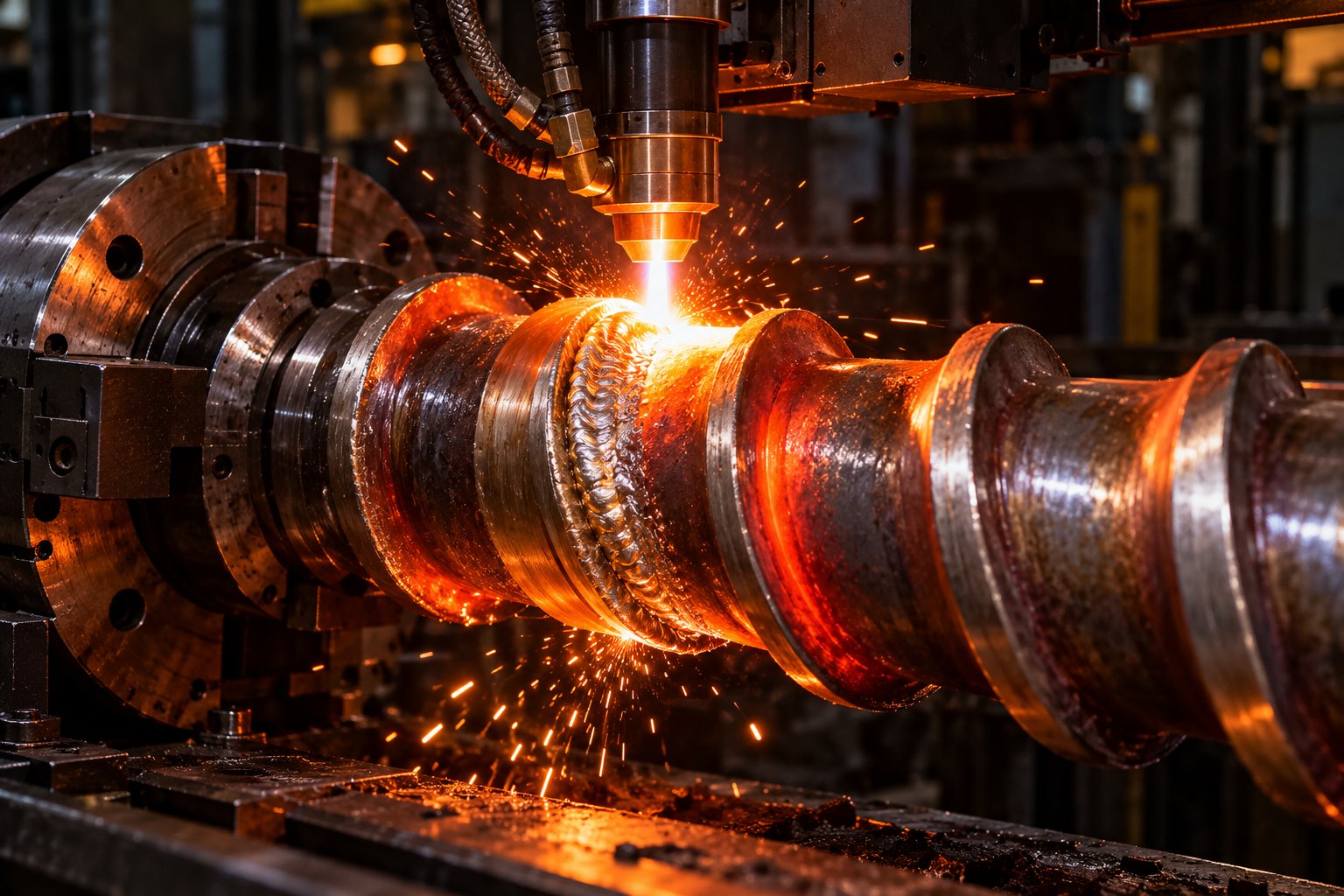
Hardfacing deposits a thick layer of wear-resistant alloy directly onto the screw's worn surfaces using a welding process. The two dominant deposition methods are plasma transferred arc (PTA) welding and laser cladding. Both create a full metallurgical bond between the overlay material and the base screw steel - not just a surface coating sitting on top, but a fused layer that becomes part of the component.
PTA hardfacing is the more established method. A plasma arc melts a stream of powdered alloy onto the screw surface, building up flight lands to their original dimensions or even slightly oversized for final grinding. Experienced refurbishment shops report that PTA welding on flight crests - after a base metal repair - can more than double the service life of the rebuilt section compared to the original nitrided surface. The dual-alloy compositions used (typically nickel, tungsten, and cobalt blends) resist both abrasion and corrosion simultaneously.
Laser cladding offers finer control. The laser beam's infinitely controllable heat input produces a minimal heat-affected zone (HAZ) and very low dilution of the overlay material with the base metal. This matters because excessive dilution reduces the overlay's hardness and wear resistance. Laser cladding also handles thin sections, sharp edges, and complex geometries that PTA may struggle with - making it well suited for rebuilding mixing elements and barrier flights where tight dimensional control is essential.
The choice between stellite and tungsten carbide overlay materials depends on the dominant wear mode:
- Stellite alloys (cobalt-chromium-tungsten compositions) deliver excellent resistance in combined corrosion-abrasion environments. They maintain hardness at elevated temperatures better than most alternatives, which makes them a strong choice for metering zone flight rebuilds where the screw contacts fully molten, potentially corrosive polymer. Stellite also machines and grinds more predictably than carbide-based overlays.
- Tungsten carbide composites provide extreme abrasion resistance for screw extruders processing glass-filled, mineral-filled, or other highly abrasive compounds. The carbide particles embedded in a metallic matrix create a surface that dramatically outlasts both chrome and stellite in aggressive abrasive environments. The tradeoff is that tungsten carbide is harder to machine to final dimensions and can be more brittle if improperly applied.
During the hardfacing process, flight geometry is actively rebuilt. The overlay is deposited to slightly oversize dimensions, then precision-ground back to the target flight OD, width, and profile. This grinding step is critical - it determines the final clearance between the rebuilt screw and the barrel bore, and any errors here undermine the entire reconditioning investment.
Re-Nitriding and Bimetallic Barrel Relining
Chrome plating and hardfacing address the screw side of the equation. Barrel reconditioning requires its own set of techniques, because you're working with an enclosed bore rather than an accessible external surface.
Re-nitriding applies to nitrided alloy steel screws and certain barrel constructions where the original surface hardening has worn through. Nitriding - either gas nitriding or ion (plasma) nitriding - diffuses nitrogen into the steel surface to create a hard case layer. When abrasive or adhesive wear removes that case, the softer core material underneath erodes rapidly. Re-nitriding can restore the hard surface layer, but only if the underlying steel still has enough dimension remaining to function within tolerance after treatment. It's most effective for screws with light-to-moderate surface wear that haven't lost significant flight geometry.
Bimetallic barrel relining is the primary restoration technique for worn barrels. The process involves centrifugally casting a new wear-resistant alloy liner inside the existing barrel tube. The barrel is heated, a measured charge of liner alloy (typically iron-boron or nickel-cobalt-based compositions) is introduced, and the barrel is spun at high speed so centrifugal force distributes the molten alloy evenly against the bore wall. The result is a metallurgically bonded liner that can match or exceed the wear resistance of the original.
After relining, bore honing brings the internal diameter to its specified dimension and surface finish. This step uses a vertical or horizontal honing machine to achieve the roundness, straightness, and surface roughness the application demands. As one refurbishment specialist details, correcting ovality first with a horizontal boring machine - restoring true roundness and straightness - is essential before final honing to size. Skipping that step locks the new liner into the old barrel's misalignment.
For barrels with localized bore damage rather than full-length wear, bore grinding and re-nitriding offer a less invasive alternative. The bore is ground to restore roundness, then nitrided to re-harden the surface. This approach works best when wear is limited to a specific zone and the barrel's base tube integrity remains sound.
| Service Technique | Best Application | Expected Service Life Extension | Limitations |
|---|---|---|---|
| Hard Chrome Plating | Light screw wear; corrosion protection; improved lubricity and cleanability on channel and root surfaces | Moderate - extends useful life meaningfully when applied to lightly worn screws; prevents surface degradation on new screws | Cannot rebuild heavy dimensional loss; not applied to flight tips; micro-cracks allow acid penetration without multi-layer treatment |
| PTA Hardfacing (Stellite) | Moderate-to-heavy flight wear in corrosion-abrasion environments; metering zone rebuilds for corrosive resins | Significant - rebuilt flights can last two or more times the life of original nitrided surfaces | Higher heat input than laser cladding; requires compatible base metal; needs precision grinding to final dimensions |
| Laser Cladding (Tungsten Carbide) | Severe abrasive wear from glass-filled or mineral-filled compounds; complex mixing element geometry rebuilds | Significant to substantial - carbide overlays dramatically outlast other treatments in abrasive service | Higher equipment cost; carbide overlays are harder to machine; brittle if improperly applied; requires specialized shops |
| Re-Nitriding (Gas or Ion) | Nitrided steel screws with light-to-moderate surface wear; barrels with localized case depletion | Moderate - restores surface hardness but does not rebuild lost dimensions | Only effective if sufficient base material remains; cannot restore flight geometry; repeated re-nitriding has diminishing returns as case depth decreases |
| Bimetallic Barrel Relining | Full-length barrel bore wear; upgrade opportunity to higher-performance liner alloys | Substantial - a properly relined barrel can approach or match new barrel performance and service life | Requires sound base tube; not economical for barrels with external damage or cracking; significant turnaround time |
Notice that none of these techniques is universally "best." A chrome-plated screw running neat polyethylene lives a very different service life than a tungsten-carbide-hardfaced screw processing 40% glass-filled nylon - and each solution is perfectly matched to its context. The technique only delivers value when it's paired with the right base material, applied to the right severity of wear, and targeted at the right zone of the screw or barrel.
That last point - base material compatibility - introduces a dimension many processors overlook entirely. The steel alloy your screw or barrel is made from determines which of these reconditioning techniques will bond properly, which might cause cracking, and which are simply incompatible. Ignoring that metallurgical reality is one of the most expensive mistakes in the entire service process.
How Screw and Barrel Materials Shape Service Options
Every reconditioning technique described so far — chrome plating, hardfacing, re-nitriding, relining — assumes the base material underneath will cooperate. That assumption fails more often than most processors realize. A stellite weld overlay that bonds perfectly to one alloy can crack and delaminate on another. A nitriding cycle that restores full surface hardness on a purpose-built nitriding steel barely improves a standard carbon steel at all. Before you authorize any extruder repair, you need to know what metal your components are actually made from.
Nitrided Steel Screws and Barrels
The most common screw materials in both extrusion and injection molding are nitrided alloy steels — typically AISI 4140 and 4340 variants that have been gas or ion/plasma nitrided to create a hard surface case. This case layer is remarkably effective against moderate abrasion and adhesive wear, but it has a finite thickness — usually between 0.007 and 0.015 inches deep depending on the nitriding cycle, with the hardest and most protective zone concentrated in only the first 0.002 to 0.005 inches of depth.
Here's the critical consideration for service planning: once wear penetrates through that nitrided case, the softer core material underneath erodes rapidly. As IMS Company's technical documentation notes, after the surface wears past roughly 0.007 inches, wear accelerates sharply and the screw may quickly reach a condition beyond repair. Re-nitriding can restore the hard layer, but only if enough base dimension remains. You can't re-nitride a flight that's already lost significant height — the process adds hardness, not metal.
Another constraint matters here. Standard 4140 steel produces moderate nitrided hardness, while purpose-built nitriding grades like Nitralloy 135M and H-13 achieve surface hardness exceeding the equivalent of 70 HRc — a substantial difference in wear resistance. If your extruder screw barrel was manufactured from 4140 and you're processing mildly abrasive materials, re-nitriding after light wear makes good economic sense. For more demanding applications, the original steel choice may limit how much service life any reconditioning can realistically recover.
Nitrided steels also impose limits on hardfacing. Certain weld overlay alloys generate enough heat input to crack the brittle nitrided case surrounding the weld zone. A skilled service provider will either strip the remaining nitrided case locally before welding or select a low-heat deposition method like laser cladding to minimize the thermal shock risk. Skipping that assessment leads to subsurface cracks that aren't visible until the rebuilt screw fails prematurely in service.
Bimetallic and Tool Steel Components
Bimetallic barrels take a fundamentally different approach to wear resistance. Instead of hardening the barrel's own steel surface, a separate wear-resistant alloy liner is centrifugally cast onto the inner surface of a pre-machined steel tube. That liner — typically 0.040 to 0.080 inches thick when new — does all the wear work while the outer tube provides structural strength.
These barrels can absolutely be relined, but the base tube must be evaluated first. After years of thermal cycling, high internal pressures, and potential corrosive exposure, the backing tube may have lost enough structural integrity to make relining unwise. Checking for cracks, wall thinning, and bore straightness before committing to a reline saves the cost of discovering these problems after the new liner is already cast.
The liner alloy itself varies by application. Standard bimetallic liners use nickel-boron alloys for general abrasion resistance. Carbide bimetallic liners incorporate tungsten carbide for highly abrasive compounds. Premium corrosion-resistant liners use cobalt-nickel alloys with high chromium content for aggressive resins like PVC and fluoropolymers. Relining offers an opportunity to upgrade — a barrel originally lined for commodity resins can be relined with a more aggressive alloy if your material mix has changed.
On the screw side, tool steel and powder metallurgy (PM) materials represent a step up from nitrided alloy steels. Grades like CPM9V, CPM10V, and CPM15V are produced through a gas atomization process that creates extremely uniform carbide distribution. CPM10V, with its 10% vanadium content, ranks among the most abrasion-resistant materials available for screw construction. CPM15V pushes that further with 15% vanadium. These PM steels generally accept hardfacing and coating processes more readily than standard alloys because their homogeneous microstructure reduces the risk of localized stress concentrations during welding. However, they require specialized welding procedures — standard shop practices developed for 4140 won't deliver reliable bonds on high-alloy PM substrates.
Matching Service to Material for Injection Molding and Extrusion
Injection molding screws and extruder barrels don't always use the same base materials, even when they look similar. Injection molding plasticating units face higher peak pressures, repetitive cycling between injection and recovery phases, and often process engineering resins that demand tighter melt quality tolerances. These conditions push manufacturers toward higher-performance substrates — tool steel barrel liners, PM screw materials, or at minimum higher-grade nitriding steels. Extrusion equipment running neat commodity resins, by contrast, may use standard 4140 nitrided screws and nitralloy-lined barrels perfectly effectively for years.
This difference directly affects what service options are on the table when wear develops. Here's a summary of which reconditioning techniques are compatible with each major material category:
- 4140/4340 nitrided steel screws — Re-nitriding (light wear only); hard chrome plating on channel and root surfaces; PTA or laser hardfacing on flights with careful heat management to avoid case cracking; limited build-up capacity before replacement is more economical
- Nitralloy 135M / H-13 nitrided screws — Re-nitriding with excellent hardness recovery; chrome plating compatible; hardfacing with stellite or tungsten carbide using controlled-heat methods; higher initial hardness means longer intervals before service is needed
- CPM tool steel and PM screws (CPM9V, CPM10V, CPM15V) — Hardfacing generally well accepted due to uniform microstructure; specialized welding procedures required; chrome plating compatible; re-nitriding not typically applicable as these rely on inherent carbide hardness rather than a nitrided case
- Nitrided alloy steel barrels — Bore grinding and re-nitriding for localized wear; not recommended for abrasive or corrosive service even after reconditioning; full relining with bimetallic liner is the preferred upgrade path
- Bimetallic barrels (nickel-boron, tungsten carbide, or cobalt-nickel liners) — Full relining with same or upgraded alloy; base tube integrity must be confirmed before relining; bore honing to final dimension after relining; liner alloy can be changed to match evolving production requirements
- D-2 tool steel lined barrels — Relining possible; original D-2 liner provides good wear resistance for non-abrasive applications at RC 58-60 hardness; can be upgraded to CPM or bimetallic liner if wear demands have increased
The single most important takeaway? Always confirm the original material specification before authorizing any service work. If OEM drawings aren't available, a reputable service provider can perform basic metallurgical testing — hardness checks, spark testing, or even spectrographic analysis — to identify the alloy before recommending a reconditioning path. Applying the wrong process to an unknown substrate is a gamble that rarely pays off.
Material compatibility tells you which techniques will work. But the resin running through the machine creates its own set of demands — abrasive fillers, corrosive byproducts, and contaminated feedstocks each attack an extruder screw barrel in distinct ways that call for very different service strategies.
Material-Specific Wear Patterns and Service Approaches
Two identical extruder screws installed in two identical machines can wear at dramatically different rates — and in completely different ways — depending on what's being pushed through them. One screw processing neat HDPE might look nearly new after several thousand hours. Another running 40% glass-filled nylon could be worn past tolerance in a fraction of that time. The resin you process doesn't just affect how fast your screw and barrel wear. It dictates how they wear, where the damage concentrates, and which service strategy actually makes sense when reconditioning or replacement time comes.
Choosing the right protective treatments without considering the material being processed is like choosing tires without knowing the road surface. You need to match the fix to the specific attack your equipment faces every production hour.
Abrasive Materials Like Glass-Filled Nylon and Mineral-Filled Compounds
Glass fibers, mineral fillers, calcium carbonate, talc, and other reinforcing agents are among the harshest substances your extruder screws and extrusion barrels will ever encounter. These particles are harder than most screw and barrel alloys, and they act like microscopic grinding media as they're conveyed, compressed, and sheared through each processing zone.
The wear pattern is distinctive. Flight lands erode preferentially because they experience the highest contact pressure against the barrel bore. The leading edges of each flight take the worst beating in the feed section, where solid pellets loaded with rigid filler particles scrape forward under compression. Barrel bore surfaces also erode, particularly in the transition zone where partially melted material still contains intact filler particles pressed outward against the bore wall by centrifugal and pressure forces.
As Jeff Kuhman of Glycon Corp. points out, glass- and mineral-filled resins can also wear the screw root, usually in the rear of the channel before the filler fully wets and mixes with melted plastic. That root erosion changes effective channel depth and compression ratio — a subtle but significant alteration to the screw's designed melting behavior. Some of the most aggressive fillers can reduce useful screw and barrel life by 50% or more compared to running unfilled polymer on the same equipment.
What does this mean for service? Light protective treatments like hard chrome plating won't survive in these conditions — the thin chrome layer wears through quickly under constant abrasive bombardment. Instead, these applications demand:
- Tungsten carbide hardfacing on screw flights — PTA or laser-clad carbide overlays create a surface hard enough to resist glass fiber erosion for extended service intervals
- Bimetallic barrel liners with high-hardness carbide alloys — Standard nickel-boron liners help, but barrels utilizing centrifugally cast alloys with high tungsten carbide content provide the longest life in abrasive service
- Compatible screw and barrel alloy pairing — Using the hardest possible barrel liner with a softer screw flight material creates a galling risk. Both components need matched metallurgy so they work together without scoring each other
Imagine running a 30% glass-filled polyamide through a standard nitrided screw with a nitralloy-lined barrel. You'll notice flight OD loss within months. Rebuild that same screw with tungsten carbide flight overlays and pair it with a carbide bimetallic barrel, and the service interval can extend several times over — a massive difference in total cost of ownership.
Corrosive Resins Including PVC and Fluoropolymers
Abrasion is a mechanical attack you can see under a magnifier. Corrosion is a chemical attack that eats metal from the inside out — and it demands an entirely different service philosophy.
PVC is the most widely processed corrosive resin. At elevated processing temperatures, PVC releases hydrochloric acid (HCl) as a byproduct of thermal degradation. As Viplas's technical guide details, this acid aggressively attacks components with a high iron matrix — which includes the vast majority of standard screw and barrel steels. The corrosive environment means that PVC processing equipment must be manufactured from corrosion-resistant materials such as special stainless steels, nickel alloys, or PVD-coated surfaces from the outset. Fluoropolymers like PTFE and FEP create similarly hostile conditions, generating hydrofluoric acid at processing temperatures — an even more aggressive corrosive agent than HCl.
The wear pattern in corrosive service looks fundamentally different from abrasive wear. Rather than localized flight-tip erosion, you'll see broad surface degradation: pitting across channel surfaces, roughening of the barrel bore, and metallurgical weakening that makes the surface vulnerable to mechanical wear that follows. As Glycon Corp.'s analysis explains, corrosion gradually destroys the metal surface, and the breakdown actually allows the surfaces to become vulnerable to additional mechanical wear mechanisms — a compounding effect where chemical and physical damage accelerate each other.
Service for corrosion-damaged components must account for both dimensional loss and metallurgical degradation. A screw that merely measures within flight tolerance might still be compromised if the surface chemistry of the base metal has changed. Effective service approaches include:
- Nickel-based or cobalt-chromium alloy coatings on screws — These resist HCl attack far better than iron-based alloys or standard chrome plating
- Multi-layer hard chrome plating — Double or triple chrome layers offset the micro-crack porosity issue that allows acid to reach the bond layer, providing a reasonable barrier for PVC service
- Corrosion-resistant bimetallic barrel liners — Cobalt-nickel alloys with high chromium content are specifically formulated for PVC and fluoropolymer environments
- Precise temperature control during processing — PVC has a very narrow processing window where temperatures high enough for uniform melting but low enough to minimize HCl generation must be maintained. Barrel and screw service that restores tight bore dimensions helps maintain this narrow thermal balance
One additional detail processors frequently overlook: PVC equipment often requires degassing systems to remove HCl vapors before they concentrate and accelerate barrel bore corrosion. If your screw and barrel service plan doesn't include inspecting vent ports and degassing zones for corrosion damage, you're missing a major failure point.
Recycled and Contaminated Feedstocks
Here's where things get unpredictable. Processing recycled plastics means dealing with feedstocks that can contain virtually anything — metal fragments from shredding operations, paper labels, mixed polymer types with different melt points, inconsistent filler loadings, and contaminants that nobody put on the material data sheet because nobody fully knows what's in the bale.
This unpredictability creates a unique wear challenge. As Santa Fe Machine Works emphasizes, ensuring that materials are free from contaminants that could exacerbate wear is a key mitigation strategy — but with recycled streams, that level of control often isn't achievable. Metal fragments cause sudden, localized damage: scored barrel bores, chipped flight edges, and gouged hardfacing. Paper and fiber contaminants combine with moisture to accelerate corrosion in hot zones. Mixed polymers with different viscosities and melt temperatures create uneven flow patterns that generate localized adhesive wear in areas the screw design never anticipated.
The practical consequence? Standard service intervals built around running virgin material simply don't apply. A screw and barrel set that would last years on neat polypropylene might need inspection after months of processing post-consumer recycled content with variable contamination levels. More frequent pull-and-measure cycles become a necessity, not a luxury.
Effective protection for recycled-material service combines multiple strategies:
- Magnetic separation and screening upstream of the feed throat to catch metallic contaminants before they reach the screw
- Abrasion-resistant screw treatments (hardfacing) paired with corrosion-resistant barrel liners, since you may encounter both attack modes simultaneously
- Shortened inspection intervals driven by process trending data rather than fixed calendar schedules
- Maintaining spare extruder screws so a worn set can be pulled for reconditioning without halting production
| Material Type | Primary Wear Mode | Recommended Screw Treatment | Recommended Barrel Treatment |
|---|---|---|---|
| Glass-filled nylon and mineral-filled compounds | Severe abrasion on flight lands, flight OD, and barrel bore; root erosion behind solid bed | Tungsten carbide hardfacing on flights; PM tool steel substrate for high-demand applications | Carbide bimetallic liner with high tungsten carbide content; bore honed to tight tolerance |
| PVC (rigid and plasticized) | Corrosion from HCl acid generation; secondary mechanical wear on chemically weakened surfaces | Nickel-based or cobalt-chromium coatings; multi-layer hard chrome; corrosion-grade stainless substrates | Corrosion-resistant bimetallic liner (cobalt-nickel-chromium alloy); degassing zone inspection and maintenance |
| Fluoropolymers (PTFE, FEP, PFA) | Aggressive corrosion from hydrofluoric acid; combined corrosion-abrasion at elevated temperatures | High-nickel alloy coatings or Hastelloy-grade substrates; avoid high-iron compositions entirely | Premium corrosion-resistant bimetallic liner; frequent bore inspection for pitting and surface degradation |
| Recycled and contaminated feedstocks | Unpredictable combination of abrasion (metal fragments, variable fillers), corrosion (mixed polymers, moisture), and impact damage | Tungsten carbide or stellite hardfacing for dual abrasion-corrosion resistance; magnetic separation upstream | Bimetallic liner rated for abrasion and corrosion; shortened inspection intervals; spare barrel recommended |
| Neat commodity resins (PE, PP, PS) | Mild abrasive and adhesive wear; slow progression over extended operating hours | Hard chrome plating sufficient for most applications; standard nitrided steel adequate for moderate duty | Nitrided alloy steel or standard bimetallic liner; standard inspection intervals |
Notice how the table reinforces a consistent theme: the resin drives the service decision far more than the wear measurement alone. Two screws with identical dimensional wear readings may need completely different reconditioning approaches if one ran neat polyethylene and the other processed rigid PVC. The polyethylene screw might only need re-nitriding and chrome plating. The PVC screw might need its base metal evaluated for subsurface corrosion damage before any reconditioning is even considered.
Matching service techniques to material-specific wear patterns is the reactive side of the equation — responding to damage already done. The proactive side involves catching that damage early, trending it over time, and planning service interventions before they become emergencies. That's where a structured preventive maintenance schedule becomes the difference between controlled costs and unplanned shutdowns.
Building a Preventive Maintenance Schedule That Works
Knowing which service technique matches which wear pattern only helps if you catch the damage before it spirals into an emergency. Yet most processors don't have a structured extruder screw maintenance program — they run until symptoms force a shutdown, then scramble to diagnose, source parts, and get back online. That reactive approach turns a planned four-day turnaround into a two-week crisis.
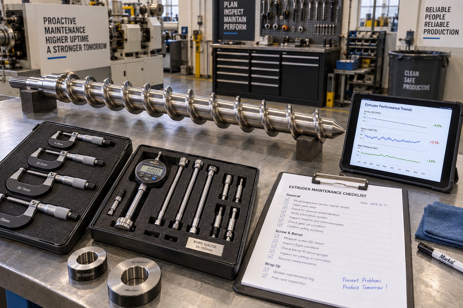
A real extruder preventive maintenance schedule isn't complicated, but it does require discipline. It operates on three levels: daily trending that reveals developing problems, weekly inspections that catch mechanical drift, and periodic pull-and-measure events that put hard numbers on wear progression. Each level feeds the next, building a data trail that transforms guesswork into scheduled action.
Daily Operator Checks and Weekly Inspections
Think of daily checks as the vital signs of your plasticating unit. Just as a doctor monitors blood pressure and heart rate to spot trouble before it becomes a crisis, your operators should be recording a small set of process indicators every shift. These aren't deep inspections — they take ten to fifteen minutes — but the trends they reveal over weeks and months are invaluable.
Four daily data points form the foundation of any meaningful screw barrel inspection schedule:
- Drive load (amps or kW) at a fixed screw speed — A gradual decline suggests the screw is losing pumping efficiency as clearances open up. A sudden spike could indicate contamination, a bridged feed section, or mechanical interference.
- Melt pressure at the die or adapter — Record this at the same screw speed and material conditions each time. As Jinxin Extruder's maintenance framework notes, rising pressure may mask screen loading or die buildup, while sudden drops may indicate feeding loss — both patterns that mimic or compound wear-related performance changes.
- Melt temperature — Climbing discharge temperatures at stable barrel setpoints suggest increased shear from higher screw speeds used to compensate for lost output, or degraded temperature control from failing heaters or thermocouples.
- Output rate (weight per unit time) — The most direct measure of screw and barrel performance. Any unexplained downward drift at constant operating conditions should trigger closer investigation.
The power of daily data isn't in any single reading — it's in the trend line. One slightly low output number means nothing. Six weeks of gradually declining throughput at the same RPM tells you the screw-to-barrel clearance is opening up and service planning should begin.
Weekly inspections go a step deeper, typically performed during planned stops, material changes, or die swaps. These tasks check the supporting systems that directly affect screw and barrel life:
- Barrel heater function — Inspect heater band terminals for discoloration, looseness, or corrosion. A failed heater zone forces adjacent zones to overwork and creates temperature gradients that accelerate localized barrel wear.
- Thermocouple accuracy — Compare displayed temperatures against a handheld pyrometer or calibration standard. Drifting thermocouples cause the controller to apply incorrect heat, potentially overheating resin and accelerating corrosive degradation in the barrel bore.
- Feed throat condition — Check for wear grooves, pellet bridging, or restricted cooling water flow. The feed throat is where solids conveying begins, and wear or blockage here cascades downstream as inconsistent feeding that stresses the entire screw length.
As the Jinxin maintenance checklist emphasizes, trending this data over time reveals gradual performance changes that signal developing wear — and a checklist is strongest when operators record only abnormal items, keeping the form short enough that it actually gets used every shift.
Scheduled Measurement Intervals and Condition-Based Triggers
Daily and weekly checks tell you something is changing. Periodic pull-and-measure inspections tell you exactly how much metal is gone and where. The question every maintenance team asks is: how often should we pull the screw?
There's no single answer, because it depends entirely on what you're processing. A machine running neat HDPE might go a year or more between pull inspections. A line processing 30% glass-filled nylon or rigid PVC should be measured far more frequently — possibly every few months — because abrasive and corrosive wear can progress rapidly between checks. The material-specific wear patterns covered earlier in this article directly dictate inspection frequency.
A practical screw barrel inspection schedule follows a tiered structure:
- Baseline measurement at commissioning or after any reconditioning — Record screw flight OD, root diameter, and barrel bore at fixed intervals along the full length. This becomes the reference point for all future comparisons.
- First follow-up at 25-30% of expected service life — This early check establishes the actual wear rate for your specific application. If the resin, filler loading, or throughput rate differs from what the OEM assumed, this first measurement catches any surprises before they become expensive.
- Subsequent inspections at regular intervals based on measured wear rate — Once you know how fast clearances are opening, you can project when they'll reach the service-recommended threshold and schedule the next measurement accordingly. For abrasive compounds, this might be every three to six months. For neat commodity resins, annually or longer may suffice.
- Pre-planned service trigger — When measurements show clearance approaching 2x the original new value (the general threshold where process impact becomes measurable), begin planning reconditioning or replacement. This is the point to engage your service provider and start the quoting process — not after the screw has worn past the point of economical repair.
- Spare component readiness check — At each scheduled measurement, confirm that a spare screw and barrel set is available or on order. If measurements indicate service will be needed within the next interval, the spare must be in hand before the next planned shutdown.
Beyond scheduled intervals, certain events should trigger an immediate pull-and-measure regardless of where you are in the calendar. These condition-based triggers override any fixed schedule:
- Sudden output drop exceeding normal process variation at constant operating conditions
- Unexplained pressure changes — either sustained increases or decreases not attributable to screen packs, die changes, or material lots
- Visible material degradation — black specks returning shortly after purging, persistent gels, or discoloration that doesn't correlate with material or temperature changes
- Metallic particles appearing in the extrudate or screen pack, indicating active metal-to-metal contact
- Processing a new resin or filler with significantly different abrasive or corrosive characteristics than the previous material
Any one of these signals warrants pulling the screw and measuring both components against their baseline data before the problem compounds further.
One practical element ties this entire maintenance framework together: supply chain readiness. The best inspection schedule in the world doesn't help if measurements reveal the need for replacement and your lead time for new components stretches into months. Having a reliable source for replacement extruder screws and barrels — ideally with spare sets pre-ordered as part of your maintenance planning — is what separates a controlled service event from a production emergency. Factory-direct suppliers like NANHAIYA offer custom and replacement screw barrels for both extrusion and injection molding applications, giving processors and maintenance teams a sourcing channel to pre-order spare components before measurements indicate that service or replacement is imminent. Treating spare component procurement as a maintenance activity, not a reaction to failure, is what keeps planned shutdowns planned.
Even with the tightest preventive maintenance program, the day eventually comes when measurements confirm that service or replacement is needed. At that point, the questions shift from "when" to "how" — specifically, whether reconditioning the existing components makes more economic sense than replacing them, and what information your service provider needs to deliver an accurate quote and fast turnaround.
Preparing Your Equipment for Professional Screw Barrel Service
You've pulled the screw, measured both components, and confirmed what the trending data already suggested — clearances have crossed the threshold where process adjustments can no longer compensate. The next decision carries real financial weight: do you recondition these components or replace them? And either way, how do you move through the service process without turning a planned maintenance event into an extended production outage?
Getting this phase right depends less on technical metallurgy and more on preparation, communication, and supply chain discipline. The processors who handle it smoothly aren't necessarily running bigger operations — they're the ones who walked into the decision with the right information already organized.
Repair Versus Replace Decision Framework
The instinct to default to repair because it seems cheaper — or to replace because it feels safer — both lead to poor outcomes when applied reflexively. The smarter approach weighs several factors against each other, and the right answer changes depending on where each factor falls.
Consider the degree of wear first. A screw with moderate flight OD loss concentrated in one zone is an excellent reconditioning candidate. A screw with heavy wear across all three zones, combined with root erosion and mixing element degradation, may cost nearly as much to rebuild as a new replacement — and the rebuilt component still carries the fatigue history of its original service life. As one comprehensive repair guide frames it, repair costs must be evaluated against the expected remaining service life of the repaired component — not just against the upfront price of a new one.
Cost comparison is the second factor, but it has to include the full picture. The purchase price of a new screw or barrel reconditioning for extruders is only one line item. Add the cost of downtime during the service window, the risk of a reconditioned component failing sooner than projected, and the energy and scrap costs of running worn components longer while waiting for service to be completed. Sometimes spending more upfront on replacement delivers a lower total cost over the next service cycle.
A third consideration that many processors overlook: replacement offers a design improvement opportunity. If your original screw geometry was a general-purpose design and your production mix has shifted toward more demanding materials, a new screw can incorporate barrier flights, optimized compression ratios, or upgraded metallurgy that a reconditioning process simply cannot add to the existing part. Reconditioning restores what was there. Replacement lets you build what should be there.
| Factor | Favors Repair | Favors Replacement |
|---|---|---|
| Degree of wear | Wear is localized to one or two zones; flight geometry is largely intact; base material is sound | Wear spans all zones; flight geometry severely degraded; root erosion or metallurgical damage present |
| Cost comparison | Reconditioning cost is well below 50-60% of new component price; reconditioning restores full functionality | Reconditioning cost approaches or exceeds 60-70% of new price; rebuilt component offers shorter expected life |
| Expected remaining service life | Reconditioned component is projected to run at least one full service interval before needing attention again | Reconditioned component likely requires service again within a fraction of a full interval |
| Design improvement opportunity | Current screw design is well matched to the resin and application; no performance gaps to address | Production mix has changed; barrier flights, different compression ratio, or upgraded metallurgy would improve performance |
| Production urgency | Reconditioning turnaround is shorter than new component lead time; production cannot wait | Spare components are on hand or lead time for new parts fits within the planned shutdown window |
| Base material condition | Substrate alloy is suitable for the chosen reconditioning technique; no cracking or fatigue indicators | Base material is degraded, unknown, or incompatible with reconditioning methods that would address the wear pattern |
This framework isn't a formula that spits out a single answer. It's a structured way to organize a conversation — internally with your maintenance and operations teams, and externally with your extruder screw repair service provider. When multiple factors cluster on the repair side, reconditioning is the smart play. When several point toward replacement, trying to save money through repair often costs more in the long run through shorter intervals between service events and compromised process performance in between.
Information to Gather Before Contacting a Service Provider
Here's where preparation pays for itself in both turnaround time and quote accuracy. A service provider who receives a phone call saying "my screw is worn and I need it fixed" has almost nothing to work with. They'll ask a dozen follow-up questions, wait for answers, and quote conservatively because they're working with incomplete data. A processor who sends a complete information package upfront gets a precise quote faster and avoids the back-and-forth that stretches lead times.
Before reaching out, gather the following:
- OEM screw and barrel drawings or part numbers — These provide the original dimensional specifications, material callouts, and flight geometry details that any reconditioning or screw barrel replacement effort needs as its reference baseline. If drawings aren't available, provide the machine manufacturer, model, and serial number so the service provider can source the specifications.
- Current wear measurements — Flight OD readings, barrel bore readings, and root diameter checks at multiple points along the length. The more complete your measurement data, the more accurately a provider can assess whether reconditioning is viable and which technique is appropriate.
- Material processed and approximate hours of operation — A screw that ran neat polypropylene for 15,000 hours has a very different wear profile than one that processed 30% glass-filled nylon for 4,000 hours. This context helps the provider anticipate the type of wear damage — abrasive, corrosive, or combined — even before they see the components.
- Specific problems observed — Output loss, surging, melt quality issues, black specks, rising drive load. These symptoms help the provider correlate what they'll find dimensionally with what's happening functionally on the production floor.
- Production urgency and shutdown timeline — Be honest about your schedule. If you have a planned shutdown in six weeks, the provider can plan accordingly. If you're already down and every day costs real revenue, they need to know that upfront to prioritize your job and flag any screw barrel replacement options that might get you running faster than a full reconditioning cycle.
- Barrel heater and thermocouple condition — If your weekly inspections revealed issues with supporting hardware, mention them. A freshly reconditioned screw installed into a machine with failed heater zones or drifting thermocouples won't deliver the expected performance improvement.
Providing this information as a package — ideally in a single email with measurements attached as a spreadsheet or PDF — eliminates the biggest source of quoting delays. It also signals to the service provider that you're an informed customer who has already done the diagnostic groundwork, which often translates to more focused technical recommendations and fewer generic upsells.
Minimizing Production Downtime During Service
The most expensive part of any screw and barrel service event isn't the reconditioning invoice or the cost of new components. It's the production time lost while your machine sits idle waiting for parts. Every strategy for minimizing downtime comes back to one principle: separate the service timeline from the production timeline so they don't overlap any more than the physical screw swap requires.
Maintain a spare screw and barrel set. This is the single most effective downtime reduction strategy available. When measurements indicate that service is needed, you pull the worn set, install the spare, and restart production the same day. The worn components ship to the service provider on your schedule, not under emergency pressure. As SDI's spare parts management analysis highlights, the relationship between spare parts availability and equipment uptime is straightforward — the more readily available spare parts are, the quicker equipment can be repaired and the less downtime accumulates. For plastic extruder screw barrel service specifically, a spare set transforms a potential multi-week outage into a few hours of mechanical changeover.
Schedule service during planned shutdowns. Coordinate your pull-and-measure inspections with annual maintenance windows, holiday shutdowns, or product changeover periods when the line would be down anyway. If measurements show reconditioning is needed, the components can ship immediately to the service provider, and the rebuilt set returns before the next production run starts. This approach only works if you're measuring proactively rather than waiting for symptoms to force the issue.
Establish relationships with suppliers who stock standard components. Custom screw designs require manufacturing lead time that can't be compressed below a certain floor. But many extruder configurations use standard geometries and common diameters that a well-stocked supplier can deliver far faster than a full custom build. Factory-direct suppliers like NANHAIYA provide custom and replacement screw barrels for extrusion and injection molding, offering processors and maintenance teams a sourcing option that can shorten lead times when building proactive replacement inventories. Pre-ordering a spare set based on your current screw and barrel specifications — before measurements indicate imminent need — means the replacement is sitting on your shelf when the data says it's time to swap.
Stagger screw and barrel service when possible. If measurements show the screw is worn but the barrel still has life remaining (a common situation, since bimetallic barrels often last about three times longer than screws), replace or recondition the screw now and plan barrel service for a future shutdown. This avoids the unnecessary cost and downtime of servicing both simultaneously when only one component has reached its threshold.
Document everything for faster repeat service. After each service event, file the measurement data, service provider quotes, reconditioning specifications, turnaround times, and post-installation performance data. The next time service is needed — and it will be, because wear is continuous — this documentation lets you skip the diagnostic phase entirely and move straight to quoting and scheduling. Over multiple service cycles, this history also reveals your true wear rate, allowing increasingly precise predictions of when the next event will fall.
Barrel reconditioning for extruders and screw replacement aren't one-time events. They're recurring chapters in the lifecycle of every plasticating machine. The processors who manage them most effectively treat each service event not as an isolated emergency but as a data point in a long-term maintenance strategy — one where measurements drive decisions, spare components prevent crises, and the right service technique is matched to the specific wear pattern every time.
Frequently Asked Questions About Plastic Extruder Screw Barrel Service
1. How do I know when my extruder screw and barrel need service?
The clearest indicators are gradual in nature rather than sudden. Watch for declining output at constant screw RPM, rising melt temperatures without setpoint changes, surging or pulsing extrudate dimensions, and black specks that return shortly after purging. When operators begin stacking process adjustments — higher screw speed, elevated barrel temperatures, increased back pressure — to maintain acceptable quality, the screw-to-barrel clearance has likely opened beyond the range where parameter tweaks can compensate. Trending daily drive load, melt pressure, and output rate over weeks reveals these patterns before they escalate into emergency shutdowns.
2. What is the difference between reconditioning and replacing an extruder screw or barrel?
Reconditioning restores worn components to functional dimensions using techniques like hard chrome plating, hardfacing with stellite or tungsten carbide, re-nitriding, or bimetallic barrel relining. It is most cost-effective when wear is localized to one or two zones and the base material remains structurally sound. Replacement involves manufacturing an entirely new screw or barrel, which becomes the better option when wear spans all zones, reconditioning costs approach 60-70% of new component pricing, or when a design upgrade — such as barrier flights or improved metallurgy — would benefit production. Factory-direct suppliers like NANHAIYA (nhyscrews.com/products) offer custom and replacement screw barrels for both extrusion and injection molding, helping processors maintain spare inventories that support either path.
3. How often should extruder screws and barrels be inspected for wear?
Inspection frequency depends heavily on the materials being processed. Machines running neat commodity resins like PE or PP may only require a pull-and-measure inspection annually or longer. Equipment processing glass-filled compounds, mineral-filled resins, or corrosive polymers like PVC should be inspected every three to six months due to accelerated wear rates. A practical approach involves taking a baseline measurement at commissioning, performing a first follow-up at roughly 25-30% of expected service life to establish the actual wear rate, then scheduling subsequent checks based on measured clearance progression. Condition-based triggers — such as sudden output drops or metallic particles in the extrudate — should override any fixed calendar schedule.
4. Can you hard chrome plate extruder screw flight tips to reduce wear?
In most cases, screw flight tips are masked off during hard chrome plating. The contact stress between the flight OD and barrel bore exceeds the chrome layer's bond strength of approximately 6,000 psi, causing the coating to wear through rapidly in that high-contact zone. Chrome plating is effective on channel walls and root surfaces, where it provides corrosion resistance, improved lubricity, and easier cleaning. For flight tip protection, hardfacing with stellite or tungsten carbide via PTA welding or laser cladding is the appropriate technique, as these create a full metallurgical bond capable of withstanding direct abrasive and adhesive contact with the barrel bore.
5. What information should I provide when requesting a quote for screw and barrel service?
A complete information package accelerates quoting and improves accuracy. Gather your OEM screw and barrel drawings or part numbers (or machine manufacturer, model, and serial number if drawings are unavailable), current wear measurements at multiple points along the component length, the resin and filler types processed along with approximate operating hours, specific production symptoms observed such as output loss or melt quality issues, and your shutdown timeline or production urgency. Including barrel heater and thermocouple condition is also valuable, since supporting hardware problems can undermine reconditioned component performance. Sending this data in a single organized package eliminates the back-and-forth that stretches lead times.
Written by
Nanhaiya Technical Team
Zhoushan Nanhaiya Plastic Machinery Co., Ltd.
The Nanhaiya technical team supports screw and barrel manufacturing projects through application review, technical communication, custom manufacturing coordination, and production and quality control.
Discuss Your Application
Related Articles
More insights on screw barrel technology and plastics processing.
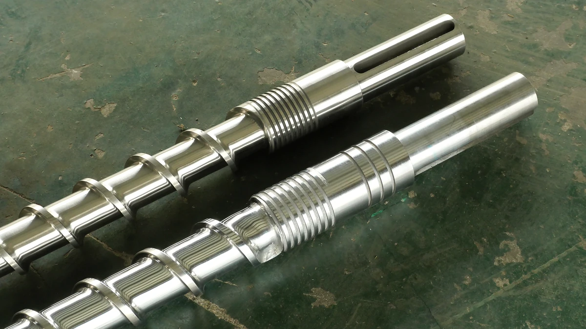
How The Wrong Extruder Screw Barrel For PP Ruins Your Melt
Oct 27, 2026
Learn why PP extrusion needs a purpose-built extruder screw barrel for PP — covering geometry, metallurgy, mixing elements, temperature profiles, and troubleshooting.
Read Article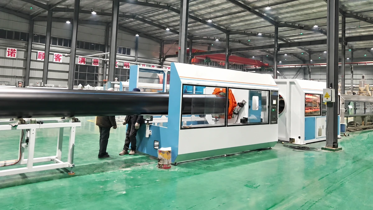
PE Pipe Extrusion Line Decoded: From Pellet to Perfect Pipe
Oct 27, 2026
Learn how a PE pipe extrusion line works — components, process steps, screw-barrel selection, vacuum calibration, automation, and a buyer's guide for smart purchasing.
Read Article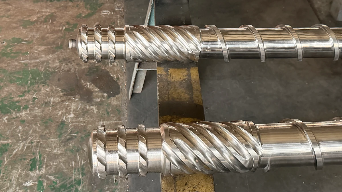
Extruder Screw Design: Match Your Polymer or Pay the Price
Oct 26, 2026
Extruder screw design guide covering geometry parameters, polymer-specific screw selection, mixing principles, wear-resistant materials, and a step-by-step design workflow.
Read ArticleLooking for something else?
Search by material, symptom or product and jump straight to the relevant page.
These are navigation suggestions based on keyword matching — not a quotation, not a delivery commitment, and not a substitute for engineering review. Final specification is confirmed by our engineers against your drawings and processed material.
Need help with screw barrel selection?
Share your machine model, processed material and application. Our team can help with pricing and technical support.