

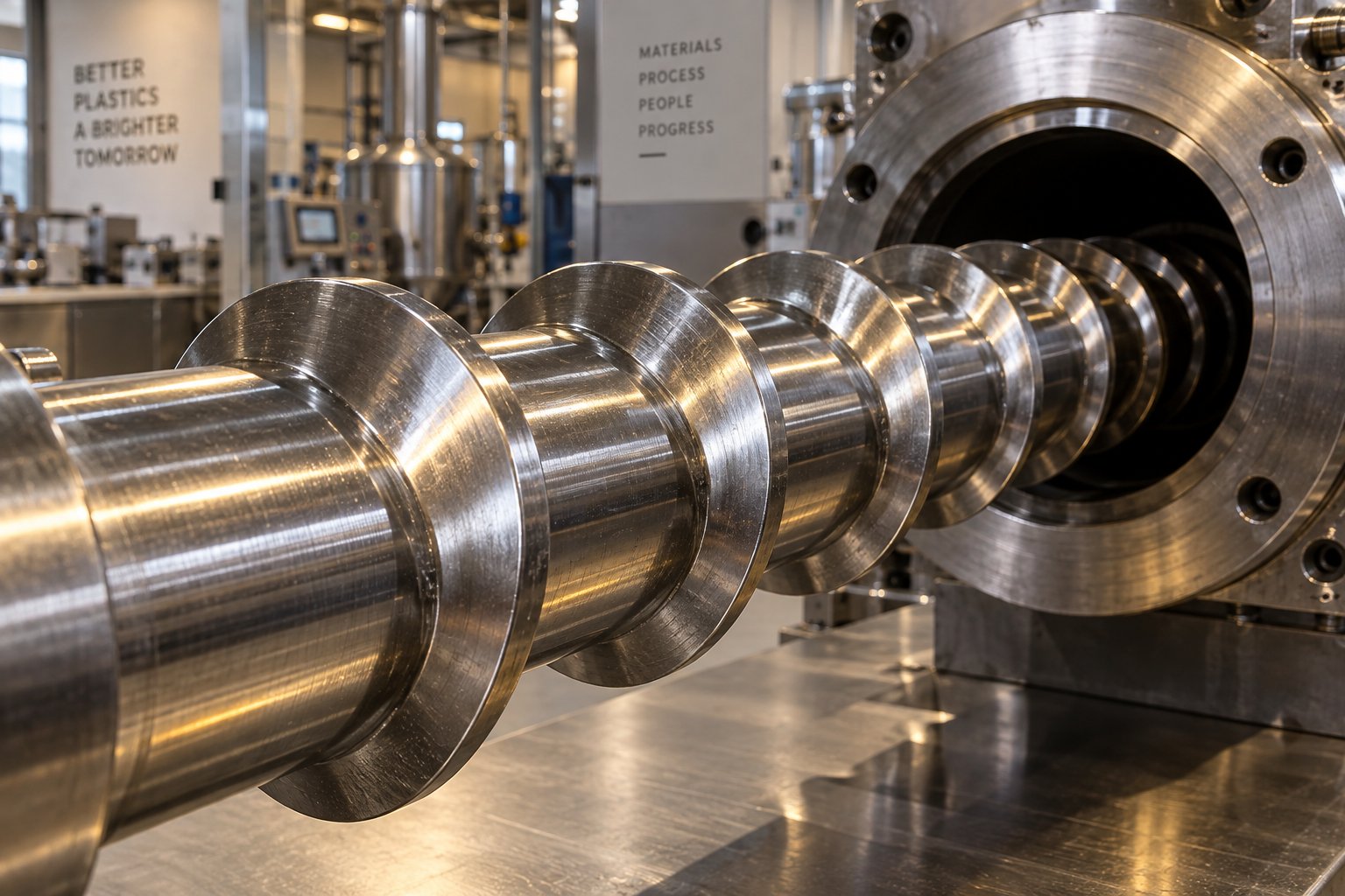
每个加工商都应该了解的挤出机螺杆更换知识
挤出机螺杆更换是指从挤出机机筒中取出磨损或损坏的螺杆,找到规格合适的替换螺杆,正确安装并校准,然后重新建立稳定的工艺参数。它是塑料加工过程中最重要的维护工作之一,也是最容易被忽视的维护工作之一。如果操作得当,它可以恢复产量、产品质量和能源效率;如果操作不当,则会使原本应该解决的问题更加严重。
挤出机螺杆更换究竟包含哪些步骤?
与其说是简单地更换零件,不如说是更全面的更换。正确的更换涉及塑化系统的每一个环节。您需要拆下原有的挤出机螺杆,检查料筒内径,确认更换的螺杆几何形状符合工艺要求,然后小心地重新安装并调试新部件。这同样适用于单螺杆挤出生产线、双螺杆混炼机和注塑机——任何挤出机螺杆和料筒协同工作,输送、熔化、混合和加压聚合物的平台都适用。
其影响范围不仅限于螺杆本身。挤出机的进料筒、过渡区和计量段都会影响螺杆的几何形状。忽略这些关系的替换方案从一开始就无法保证性能。
为什么结构化的更换流程至关重要
大多数加工商都会在这里遭遇麻烦。仓促或计划不周的更换会导致生产工时损失、大量废料堆积,以及因缺乏正确操作规程而搬运高温重型部件带来的安全隐患。更糟糕的是,将全新的螺杆安装到已经磨损到超出公差范围的筒体中,会完全浪费投资——新螺杆与筒壁之间过大的间隙会导致泄漏,降低泵送效率并升高排出温度,从而使磨损螺杆的症状再次出现。
运行不正确的启动参数会造成一系列问题:新飞行表面出现磨损、过早磨损,或者在建立基线之前树脂就发生热降解。
挤出机螺杆更换不仅仅是一项维护任务,更是一个评估和改进整个螺杆料筒系统的机会,从冶金和几何形状到工艺优化。
This article walks through the full replacement journey: recognizing the warning signs that a screw has reached end-of-life, understanding the geometry parameters you need to specify correctly, assessing barrel condition before you install anything new, sourcing the right materials and coatings, executing a safe removal and installation, and commissioning the new screw without the common mistakes that cost processors time and money. Whether you're managing a single line or overseeing maintenance across an entire plant, the goal is the same — get it right the first time so you don't pay for it twice.
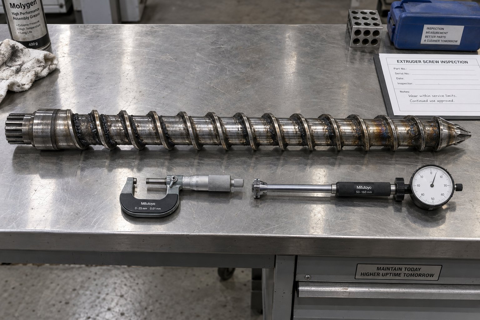
How to Tell When Your Extruder Screw Needs Replacement
Screw wear doesn't happen overnight — it creeps. Every hour of operation removes material from the flight lands, root diameter, and mixing elements. The trouble is, many processors don't recognize the symptoms until product quality has already deteriorated or output has dropped far enough to trigger alarms. Knowing what to look for — and when — turns an expensive emergency into a planned maintenance event.
Performance Indicators That Signal Screw Wear
The most reliable early warnings aren't things you can see or hear. They show up in your process data. As extruder screws wear, flight depth decreases unevenly and the effective compression ratio shifts, which degrades melt quality and reduces the screw's ability to generate consistent pressure. You'll notice the effects in measurable process deviations long before the screw looks visibly damaged.
Watch for these key warning signs:
- Declining output rate at constant RPM — a worn plastic extruder screw loses pumping efficiency as increased clearance allows polymer to leak backward over the flights instead of moving forward.
- Increased specific energy consumption — the motor works harder to achieve the same throughput, with energy consumption rising more than 15% above baseline signaling a screw that's well past marginal.
- Rising melt temperature without process changes — excessive clearance generates additional shear heating. A deviation of more than 15°F above setpoint, with no adjustments to barrel zones or RPM, is a strong indicator.
- Inconsistent product dimensions — wall thickness variation, weight fluctuation, and dimensional drift all point to unstable melt delivery caused by worn screw geometry.
- Increased motor amperage at rated RPM — torque loads climb as the screw barrel relationship degrades and conveying efficiency drops, with increases beyond 10% above baseline warranting immediate investigation.
Any one of these symptoms deserves attention. Two or more appearing together strongly suggest the screw has moved past the serviceable range.
Physical and Auditory Clues During Operation
Beyond the data, your senses can pick up signs that confirm what the numbers are already telling you. Unusual noise from the barrel zone — a metallic scraping or intermittent knocking — typically indicates metal-on-metal contact caused by excessive flight-to-barrel clearance. When screw deflection allows the flights to physically contact the barrel wall, you'll see flattened flight tips and score marks on the barrel surface, a condition known as adhesive wear.
Surging or pulsating output is another telltale sign. Imagine watching the extrudate exit the die in rhythmic pulses rather than a smooth, steady flow — that's a classic symptom of inconsistent solid bed breakup, where worn flight geometry can no longer maintain uniform melting. If you spot unmelted particles or gels in the extrudate, the screw's melting and mixing capacity has likely been compromised. Pulling the screw for visual inspection may reveal rounded flight edges, polished surfaces where sharp corners once existed, or pitting along the root diameter.
Connecting Symptoms to Root Causes
Not all screw wear looks the same, because the mechanisms driving it are different. Abrasive fillers like glass fiber or mineral additives erode flight lands progressively, rounding sharp edges and increasing clearance over time. Corrosive resins — particularly those releasing acidic byproducts during processing — chemically attack chrome or nitrided surfaces, creating a dimpled or pitted surface texture. Mechanical overload, from excessive RPM or cold-start conditions, can produce fatigue cracks or galling where metal surfaces weld momentarily and then tear apart.
Recognizing which mechanism is at work matters because it directly influences how you specify the replacement — different wear modes call for different metallurgies and coatings. The table below maps observable symptoms to their most likely cause and how urgently you need to act.
| Symptom | Likely Wear Mechanism | Replacement Urgency |
|---|---|---|
| Rounded, polished flight edges; gradual output decline | Abrasive wear (fillers, reinforcements) | Plan replacement within next scheduled shutdown |
| Pitted or dimpled screw surface; discoloration | Corrosive wear (acidic resin byproducts, moisture) | Moderate — inspect barrel also for corrosion damage |
| Score marks on flights and barrel; flattened flight OD | Adhesive wear (metal-to-metal contact, deflection) | High — continuing operation accelerates barrel damage |
| Cracks at flight root or along shank; sudden torque spikes | Mechanical overload or fatigue | Critical — risk of catastrophic screw failure |
| Surging output with rising melt temperature | Combined abrasive and adhesive wear | High — screw is past marginal condition |
| Output below 85% of rated capacity at full RPM | General end-of-life wear (multiple mechanisms) | Immediate — process is no longer economically viable |
The pattern of wear tells a story. A screw running glass-filled nylon that shows polished, rounded flights is behaving exactly as expected from abrasive erosion — the fix is a harder metallurgy on the replacement. A screw processing unfilled PVC that shows pitting and surface discoloration points to corrosive attack, demanding a different material strategy entirely. Matching the symptom to the root cause ensures the replacement screw is built to resist the specific conditions that destroyed its predecessor — rather than simply repeating the same failure cycle with fresh hardware.
Understanding Screw Geometry and Replacement Specifications
Diagnosing the wear mechanism is only half the battle. The other half — the part that separates a successful extruder screw replacement from a costly misfire — is getting the geometry right on the new component. Every extrusion screw has a specific set of dimensional parameters that govern how it conveys, melts, mixes, and pressurizes polymer. Order a replacement without verifying these parameters, and you'll end up with a screw that physically fits the machine but doesn't perform the way the process demands.
Sounds straightforward? In practice, many processors don't have the original screw drawings on file. Machines change hands, documentation gets lost, and the worn screw sitting on the shop floor is sometimes the only reference available. That makes understanding what each parameter does — and how to measure it accurately — essential knowledge for anyone involved in the specification process.
Key Geometry Parameters for Replacement Specification
Before contacting a supplier or placing an order, you need to capture or confirm a specific set of dimensions. These aren't just numbers on a print — each one directly influences how the screw plastic extruder system handles resin. Miss one, and the replacement may underperform in ways that are difficult to diagnose after installation.
Here's a breakdown of the critical parameters:
| Parameter | Definition | Why It Matters for Replacement |
|---|---|---|
| L/D Ratio | The ratio of the screw's functional flighted length to its outer diameter | Determines residence time, melting capacity, and mixing intensity. A mismatch changes the entire thermal and mechanical profile of the process. |
| Compression Ratio | The ratio of the feed zone channel depth to the metering zone channel depth | Controls how aggressively the screw densifies and melts the resin. Too high causes overheating; too low leaves unmelted material in the extrudate. |
| Feed Zone Flight Depth | The channel depth in the solids-conveying section of the screw | Governs solids intake volume. A deeper feed section enhances conveying but can weaken the screw root under high torque. |
| Transition Zone Flight Depth | The progressively decreasing channel depth in the melting section | Drives the compression and melting of polymer. The taper rate must match the resin's melting behavior to avoid surging. |
| Metering Zone Flight Depth | The constant (shallow) channel depth in the final pumping section | Determines output rate, melt homogeneity, and discharge pressure capability. Even small deviations alter throughput significantly. |
| Pitch (Lead) | The axial distance between consecutive flight turns | Affects the helix angle, conveying rate, and shear rate. Changing the pitch without adjusting other parameters shifts the entire operating window. |
| Helix Angle | The angle between the flight and a plane perpendicular to the screw axis | Influences material transport efficiency. A 17.66-degree angle (square pitch) is standard for most general-purpose screws, but specific resins and feed forms may require different angles. |
| Flight Width (Land Width) | The flat surface at the top of each flight that rides close to the barrel wall | Affects sealing between flights and barrel, leakage flow, and shear on the melt film. Narrow flights reduce sealing; excessively wide flights increase unnecessary shear. |
| Root Diameter | The diameter of the screw body at the base of the channels | Directly determines channel depth and, by extension, the compression ratio. Root wear effectively lowers the compression ratio, degrading melt quality. |
When original drawings are unavailable, these dimensions must be taken directly from the worn screw — with the understanding that wear has altered them from their original values. That's why the measurement process itself requires careful technique, which we'll cover shortly.
How Worn Geometry Affects Processing Performance
Imagine a metering zone that originally had a flight depth of 0.100 inches. After thousands of hours processing glass-filled resin, root wear has opened that depth to 0.115 inches. That 15% increase might seem modest, but it lowers the effective compression ratio across the entire screw, meaning the polymer receives less compressive work during melting. The result? Incomplete melting, poor color dispersion, reduced pressure generation at the screw tip, and lower output at the same RPM.
The clearance between the screw flights and the barrel wall is equally consequential. In a properly functioning extruder screw barrel system, this clearance is typically controlled within 0.1 to 0.65 mm. As the flight outer diameter wears down, the radial gap widens. Polymer leaks backward over the flights — a phenomenon called leakage flow — instead of being pushed forward. This backflow reduces net output, generates excessive shear heating in the resin, and creates pressure instability at the die.
The viscosity of the resin amplifies or moderates this effect. Higher-viscosity polymers like PE suffer less output loss from a given clearance increase than lower-viscosity materials like PP, because thicker melts resist leaking through narrow gaps more effectively. This means the same amount of flight wear can be tolerable on one resin and devastating on another — a critical consideration when specifying replacement tolerances.
Root wear creates its own set of problems beyond compression ratio changes. Uneven erosion on the forwarding side of the flight, which is common with abrasive compounds, opens up pockets where material can stagnate and thermally degrade. These hang-up zones produce the black specks and contamination that drive up scrap rates. In extreme cases, severe root erosion undermines the weld substrate supporting hardfaced flight tips, causing them to chip away entirely.
Measuring and Documenting Screw Dimensions
Accurate measurement is the foundation of a correct replacement specification. You're essentially reverse-engineering the screw's current condition and comparing it to what the manufacturer originally intended. Here's how experienced maintenance teams approach this:
- Flight OD measurement: Use an outside micrometer to measure the flight outer diameter at every other flight along the full screw length. Record each reading systematically so you can map the wear pattern from feed to metering zone. Focus on transition and metering sections, where wear is typically most severe due to higher pressures and temperatures.
- Root diameter measurement: Measure root diameter between every other flight, capturing readings at multiple axial orientations (0 degrees, 90 degrees, etc.) to detect ovality. Root wear is often worst on the forwarding side of the flights, so rotating the measurement point reveals asymmetric erosion that a single reading would miss.
- Flight width: Measure the land width at the flight tip using calipers. Wear and rebuild grinding can reduce effective flight width, affecting sealing performance against the barrel wall.
- Overall length and zone transitions: Document the total flighted length, the length of each functional zone (feed, transition, metering), and the location of any mixing elements or barrier flights.
What tolerance range separates a serviceable screw from one that needs replacement? Manufacturers specify this for each application, but a widely referenced guideline considers flight clearance exceeding four times the original radial tolerance as the threshold for replacement. For a screw originally manufactured with 0.002 inches of radial clearance per side, a measured clearance of 0.008 inches or greater suggests the screw has moved past its useful life. However, this rule of thumb should be viewed as a guideline rather than an absolute cutoff — the actual impact depends heavily on the viscosity of the resin being processed, the output rate required, and the quality standards of the final product.
The key takeaway: document everything during the measurement process and share those measurements with your supplier. A complete dimensional map of the worn screw, combined with the barrel bore measurements we'll discuss next, gives the manufacturer the data needed to produce a replacement that restores — or even improves — original performance. Without that data, you're guessing. And guessing is how processors end up paying for the same replacement twice.
Assessing Extruder Barrel Condition Before Installing a New Screw
That dimensional map of the worn screw tells you what the screw has lost — but it only tells half the story. The other half lives inside the barrel bore. And this is where many processors make the single most expensive mistake in the entire replacement process: they install a brand-new screw into an extruder barrel they never bothered to measure.
Why Barrel Inspection Must Precede Screw Replacement
Picture this scenario. You've identified the wear, measured every flight, specified the geometry perfectly, and received a precision-manufactured replacement screw. You install it, run the startup protocol, and within weeks, the same symptoms return — declining output, rising melt temperature, inconsistent product dimensions. What went wrong?
The barrel bore was oversized. That new screw, built to original OEM tolerances, now sits inside a barrel whose internal diameter has grown well beyond its nominal specification. The radial clearance between the fresh flight tips and the worn barrel wall is still excessive. Polymer still leaks backward over the flights. Pumping efficiency is still compromised. You've spent thousands on a replacement screw that can't perform because the barrel it lives in won't let it.
A new screw in a badly worn barrel — or a new barrel around a badly worn screw — may leave excessive clearance and shorten the life of the new component. Always evaluate screw and barrel as a matched system.
This principle applies to every configuration — single-screw extrusion lines, twin-screw compounders, and injection molding platforms alike. Extruder barrels wear just as screws do, only in the opposite direction: the bore diameter increases while the screw diameter decreases. Both changes contribute to the same problem — growing clearance that degrades process performance. Ignoring either half of the equation is like replacing one worn tire on a car and wondering why it still pulls to one side.
How to Evaluate Barrel Bore Condition
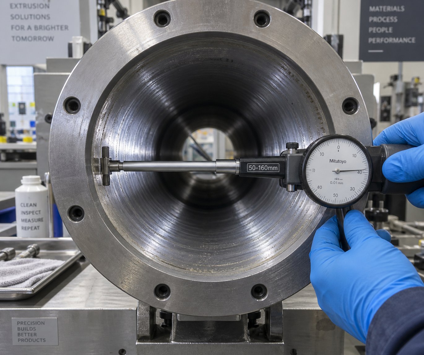
Barrel inspection is more involved than screw measurement because you're working with an internal surface you can't easily see. The goal is to determine the actual bore diameter at multiple points along the extrusion barrel length, check for ovality (out-of-roundness), and identify localized wear zones.
Here's the practical approach experienced maintenance teams follow:
- Clean the bore thoroughly. Remove all residual polymer, carbon deposits, and debris. A dirty bore produces inaccurate measurements. Allow the barrel to stabilize at a consistent temperature before measuring — thermal expansion can introduce errors of several thousandths of an inch.
- Select the right measurement tool. Telescoping gauges (T-gauges) paired with an outside micrometer are the most accessible option for most maintenance shops. For higher precision, calibrated bore gauges with dial indicators provide direct readings and faster data collection. Choose a gauge where the bore diameter falls in the middle of the tool's range to ensure adequate spring tension and reliable contact.
- Measure at multiple axial positions. Take readings at defined intervals along the barrel — typically at the feed section, transition zone, metering section, and any vent or mixing zones. These positions should correspond to the same axial locations where you measured the screw, so you can calculate the actual clearance at each point.
- Check for ovality at each position. Rotate your measurement 90 degrees at every location. The difference between the largest and smallest bore reading at the same cross-section reveals ovality — an indication that the barrel has worn unevenly, often from screw deflection pressing against one side. Ovality values above 0.05 mm in critical zones deserve close scrutiny.
- Focus on known high-wear zones. Extruder barrel wear is rarely uniform. The feed section and transition zone typically show the most severe bore enlargement because this is where solid pellets exert the highest abrasive forces against the barrel wall. The metering section can also show significant wear in applications running abrasive compounds at high pressures.
- Compare against original specifications. Every measurement must be referenced against the barrel's nominal bore diameter as documented in the OEM drawing or the new-condition baseline. Without this reference, raw numbers are meaningless — you need to know how much material the bore has lost, not just its current size.
A borescope inspection adds valuable qualitative data — scoring, pitting, corrosion, and deposit buildup become visible — but it doesn't replace dimensional measurement. You need both: visual evidence of surface condition and hard numbers that quantify bore enlargement.
Document every reading in a structured format. A wear report that records screw OD, barrel ID, calculated diametral clearance, ovality, and surface condition at each axial position gives you the complete picture. It also creates a historical record you can reference at the next inspection to calculate wear rate and predict when the next replacement will be needed.
Making the Replace-Screw-Only vs. Replace-Both Decision
With screw and barrel measurements in hand, the decision framework becomes straightforward. You're not guessing — you're comparing actual clearances against documented limits and making a data-driven call.
Here's how to think through it:
- Barrel wear is minimal and within OEM tolerance: Replace the screw only. The new screw's flight OD will restore proper clearance against a barrel bore that's still within acceptable limits. This is the ideal — and least expensive — scenario.
- Barrel wear is moderate, approaching tolerance limits: Replace the screw, but shorten the next inspection interval significantly. The barrel will continue to wear, and the window of acceptable clearance with the new screw is narrower than it would be with a fresh barrel. Monitor process data closely for early signs of clearance-related performance loss.
- Barrel wear exceeds tolerance at critical zones (feed, transition, or metering): Replacing only the screw yields diminishing returns. The extruder barrel should also be replaced or, if the design permits and the structural shell is sound, relined with a new bimetallic liner. A new screw in a severely worn barrel will underperform from day one and wear faster than it should because of the uneven loading created by an oversized or oval bore.
- Barrel shows deep scoring, cracking, or severe ovality: Replace the barrel. Period. These conditions indicate damage beyond normal wear — often caused by metal-to-metal contact, foreign object ingestion, or thermal distortion. No amount of screw optimization compensates for a structurally compromised extrusion barrel.
- Both screw and barrel are at or beyond tolerance: Replace both as a matched pair. This is the most expensive option upfront, but it's also the most cost-effective over the full service life because both components start at zero wear with optimal clearance.
The real cost trap isn't the price of a new barrel — it's the pattern of repeated screw replacements caused by an underlying barrel problem that nobody measured. Each new screw wears faster than its predecessor because the barrel bore keeps getting larger, and the window of acceptable clearance keeps shrinking. Two or three premature screw replacements easily exceed the cost of addressing the barrel the first time around.
This barrel assessment also shapes how you specify the replacement screw itself. If the barrel bore has enlarged slightly but remains within a workable range, some manufacturers can adjust the replacement screw's flight OD to restore optimal clearance against the current bore — a cost-effective alternative to replacing both components. Discuss this option with your supplier, and make sure you provide the barrel bore measurements alongside the screw dimensions when requesting a quote.
How to Source and Specify a Replacement Extruder Screw
Armed with screw dimensions, barrel bore data, and a clear understanding of the wear mechanism that destroyed the previous component, you're ready to source the replacement. This is where the process shifts from diagnostics to procurement — and where many processors stumble. Choosing the wrong material or coating for your operating conditions shortens service life. Choosing the wrong supplier can mean dimensional inaccuracies, missed lead times, or components that look right on paper but fail prematurely on the production floor.
Getting this step right means matching the metallurgy to your specific wear environment, then finding a supplier who can actually deliver on that specification.
Choosing the Right Screw Materials and Coatings
The wear mechanism you identified during diagnosis — abrasive, corrosive, adhesive, or a combination — dictates the metallurgy and surface treatment the replacement screw needs. A general-purpose nitrided screw handles a very different set of conditions than a bimetallic screw designed for 30% glass-fiber compounds. Specifying the wrong combination is like fitting snow tires in a desert — technically functional, but optimized for the wrong problem.
Here's how the main surface engineering options break down:
- Gas and ion/plasma nitriding — The workhorse treatment for general-purpose and moderate-wear applications. Nitriding diffuses nitrogen into the screw surface to form hard chromium nitride layers that resist wear while maintaining thermal stability at processing temperatures. Common base steels include AISI 4140 and 4340, though more demanding applications benefit from specialized nitridable steels like Nit135M and H-13, which can achieve surface hardness exceeding 70 HRC equivalent. Ion/plasma nitriding is particularly well-suited for long screws processed in vertical vacuum chambers, where uniform case depth along the entire length is critical.
- Bimetallic construction — For processors running abrasive-filled compounds, bimetallic screws feature a specialized alloy layer — typically tungsten carbide or nickel-based alloys — cast or welded onto the flight surfaces. This alloy layer offers a lifespan two to five times longer than standard nitrided screws in glass-filled or mineral-loaded service. The trade-off is higher upfront cost, but the extended replacement interval almost always delivers a lower cost per operating hour.
- Tungsten carbide hardfacing — The extreme end of the abrasion-resistance spectrum. Hardfaced flights are used when filler loadings are very high or when the abrasive particle is exceptionally hard (silicon carbide, for example). This option is typically applied to flight tips and leading edges rather than the entire screw surface.
- Cobalt-based and nickel-based weld overlays (Stellite, Colmonoy) — These alloys deliver excellent mechanical strength and corrosion resistance but have comparatively weaker adherence to the base screw material than diffusion-based treatments like nitriding. They're a strong choice for corrosion-dominated environments where chemical attack rather than particle abrasion is the primary failure mode.
- Chrome plating — Sometimes used for corrosion protection, but chrome has a different coefficient of thermal expansion than the base steel and can exfoliate at elevated processing temperatures. It's generally less reliable than nitriding for plastics extrusion applications.
The table below maps common processing scenarios to recommended material and coating combinations. Use it as a starting point — your supplier should confirm the optimal selection based on the specific resin, filler type, throughput rate, and barrel metallurgy in your application.
| Processing Scenario | Primary Wear Mechanism | Recommended Base Steel | Recommended Surface Treatment |
|---|---|---|---|
| Unfilled PE, PP, PS | Mild adhesive/abrasive | AISI 4140 or 4340 | Gas or ion/plasma nitriding |
| Glass-filled nylon, PBT (15-30% GF) | Severe abrasive | H-13 or tool steel | Bimetallic alloy (tungsten carbide based) |
| Mineral-filled PP, PE (talc, CaCO3) | Moderate abrasive | Nit135M, H-13, or 4340 | Ion/plasma nitriding or bimetallic for high loadings |
| PVC and chlorinated polymers | Corrosive (HCl release) | Corrosion-resistant tool steel | Nickel-based weld overlay (Colmonoy) or specialized nitriding |
| Highly abrasive compounds (>30% GF, SiC fillers) | Extreme abrasive | CPM 9V or equivalent PM steel | Tungsten carbide hardfacing on flights |
| Flame-retardant compounds with corrosive additives | Combined corrosive + abrasive | H-13 or corrosion-resistant alloy | Bimetallic with corrosion-resistant alloy layer |
One important nuance: the barrel's metallurgy must be compatible with the screw's surface treatment. Running a hardened bimetallic screw inside a softer, unlined barrel accelerates barrel wear — you've simply shifted the wear problem from one component to the other. Discuss both screw and barrel metallurgy with your supplier as a matched system, not as independent decisions.
What to Look for in a Replacement Screw Supplier
Material selection only matters if the supplier can actually execute it. Whether you're replacing a screw on a Davis Standard extruder, a twin-screw compounder, or an injection molding machine, the evaluation criteria remain consistent. A reliable supplier demonstrates competence across multiple dimensions — not just price.
Here's what to verify before placing an order:
- Manufacturing capability for your configuration — Can the supplier produce screws for both single-screw extrusion and twin-screw platforms? Does their equipment handle the length and diameter your machine requires? Some suppliers specialize narrowly; others cover the full range of extrusion and injection molding configurations.
- Ability to manufacture to OEM specifications or custom-optimized designs — The supplier should be able to replicate original geometry from your dimensional data or, when appropriate, propose design modifications that address the specific wear patterns or performance gaps you've identified.
- Material certifications and traceability — Insist on mill test certificates for every batch of steel used. A supplier's refusal to provide material documentation is a red flag that suggests potential use of substandard or unverified raw material.
- Dimensional inspection reports — The supplier should provide documented proof that the finished screw meets your specified tolerances. Ask whether they use coordinate measuring machines or comparable precision instruments, and request the actual measurement data — not just a pass/fail statement.
- Heat treatment capability and documentation — Whether the treatment is performed in-house or by a qualified subcontractor, you need process records confirming that the specified surface hardness and case depth were achieved. Surface hardness for nitrided screws should meet the specified values for the base steel — for example, a minimum of 950 HV with 0.40 to 0.70 mm treatment depth for standard 38CrMoAlA applications.
- Lead time and responsiveness — Custom replacement screws typically require 15 to 25 working days for production, with complex designs extending further. Understand the supplier's current backlog and whether they can accommodate expedited orders when an unplanned failure forces your hand.
- Warranty coverage — What does the supplier stand behind? A warranty that covers material defects and dimensional accuracy signals confidence in their manufacturing quality. One that excludes everything beyond shipping damage tells a different story.
- Surface finish quality — Flight surfaces should meet specified roughness requirements, typically Ra 0.8 micrometers or better for the screw body. Poor surface finish increases friction, accelerates initial wear, and can degrade polymer flow characteristics.
Requesting a live facility tour — in person or by video — remains one of the fastest ways to distinguish genuine manufacturers from trading companies that outsource production and add a markup. A real manufacturer will walk you through their CNC machining centers, grinding equipment, and heat treatment facilities without hesitation.
OEM vs. Aftermarket Replacement Options
When the screw on your Davis-Standard extruder or another US extruders platform reaches end-of-life, the default instinct is often to order directly from the original equipment manufacturer. It's familiar, requires minimal research, and guarantees dimensional compatibility. But it's rarely the only option — and frequently not the most cost-effective one.
OEM replacement channels offer a genuine advantage in convenience. The machine builder has the original drawings on file, knows the exact metallurgy and geometry, and can typically ship a replacement with minimal back-and-forth on specifications. The trade-off is price. OEM aftermarket parts often carry substantial markups — sometimes 40 to 60 percent over what a specialized screw barrel manufacturer charges for a dimensionally identical component. Lead times can also stretch longer than expected, especially if the OEM outsources its screw production to a third party and simply applies its own brand to the finished part.
Specialized aftermarket suppliers — companies whose core business is manufacturing screws and barrels rather than complete extrusion lines — represent a compelling alternative. These suppliers invest in the same CNC machining, precision grinding, and heat treatment infrastructure that the screw requires, without the overhead of building entire machines. The result is often equivalent or improved metallurgical quality at a more competitive price point, with shorter lead times driven by a production schedule dedicated entirely to wear components.
For plastic processors, equipment builders, and maintenance teams evaluating aftermarket options, factory-direct manufacturers like NANHAIYA offer a practical example of this model. NANHAIYA provides custom and replacement screw barrels for both extrusion and injection molding applications, manufacturing components to OEM specifications or custom-optimized designs. Working directly with a factory-level supplier eliminates intermediary markups and gives you direct access to the engineering team responsible for producing your component — a significant advantage when discussing metallurgy options, tight tolerances, or non-standard geometries.
The choice between OEM and aftermarket ultimately depends on your priorities. If speed and minimal specification effort outweigh cost, the OEM channel serves well. If you've done the measurement work, documented your geometry, and identified the right metallurgy for your wear conditions, a specialized manufacturer can deliver equivalent performance at a lower total procurement cost — particularly for operations managing multiple extrusion or injection molding lines where replacement frequency makes per-unit savings compound quickly.
Whichever path you choose, the screw sitting on the supplier's shipping dock is only as good as the installation process that follows. Even a perfectly specified, precision-manufactured replacement can be compromised by improper handling, incorrect alignment, or skipped safety protocols during the physical swap — a topic that deserves its own careful walkthrough.
Safe Removal and Installation of Extruder Screws
A perfectly specified screw and barrel set means nothing if someone gets hurt during the swap. Extruder screw removal and installation involve hot, heavy components, stored hydraulic energy, and rotating drive systems — a combination that demands strict procedural discipline. Rushing this phase doesn't just create safety hazards. It can also damage the new screw, score the barrel bore, or leave alignment issues that shorten component life from the very first rotation.
Lockout-Tagout and Pre-Removal Safety Protocols
Before anyone picks up a wrench, the machine must be fully de-energized and verified. Lockout-tagout isn't a suggestion — it's a regulatory requirement, and skipping it has proved fatal on multiple occasions. OSHA standards require that all hazardous energy sources be isolated and rendered inoperative before maintenance work begins. For an extruder, that means addressing every energy type the machine contains:
- Electrical: Disconnect and lock out the main drive motor, barrel heater circuits, and any auxiliary controls. Apply individual locks — each worker places their own lock on every energy-isolating device.
- Hydraulic and pneumatic: Bleed hydraulic accumulators and pneumatic lines to zero pressure. On injection molding machines, the injection screw's hydraulic drive system stores significant energy even after shutdown.
- Mechanical: Block any components that could move under gravity. Verify that the screw cannot rotate by attempting a manual start after lockout — push the start button to confirm zero response.
- Thermal: This one requires judgment rather than a simple off switch. Some polymers — PVC and certain engineering resins — must be purged while the barrel is still at processing temperature, because allowing them to cool and solidify inside the extrusion screw barrel creates a removal nightmare. Others, like polyolefins, can be purged and then allowed to cool. Know your resin's behavior before deciding on the thermal protocol.
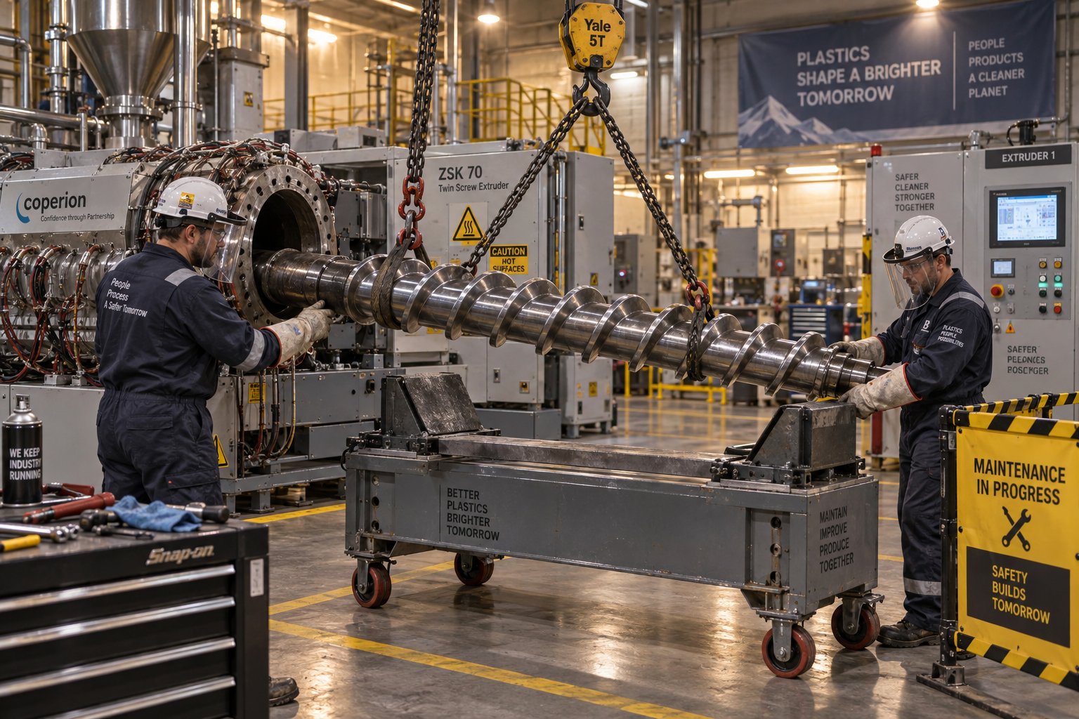
Required PPE includes heat-resistant gloves rated for contact with surfaces above 400°F, face shields, steel-toed boots, and long sleeves. The screw itself can weigh hundreds of pounds on larger machines, so rigging equipment — chain hoists, slings, or screw carts — should be staged and inspected before beginning the pull.
Step-by-Step Screw Removal Procedure
With lockout confirmed and PPE in place, the physical removal follows a specific sequence. Deviating from this order — or using brute force when something binds — is how barrels get scored and drive components get destroyed. One facility used a forklift to ram a 10-inch screw that had bound in the drive sleeve. Years later, extraction required an oversized hydraulic jack and left massive gouges on the drive shank and severe damage to the sleeve. The lesson: if it doesn't move freely, stop and diagnose — don't force it.
Here's the proper sequence:
- Close the feed throat slide gate or empty the hopper to stop material flow into the barrel.
- Purge the barrel at low RPM using an appropriate purge compound until no more resin exits the die. For heat-sensitive resins, use a stabilized purge grade that resists degradation during the extended residence time.
- Remove the die assembly, adapter, and any downstream tooling while the equipment is still hot. This exposes the discharge end of the barrel for screw extraction.
- Disconnect the drive coupling between the gearbox output shaft and the screw shank. On injection molding platforms, disconnect the injection screw from the hydraulic piston assembly.
- Push the screw forward out of the barrel using a hydraulic push-jack or threaded pusher from the feed end. Advance the screw in increments — roughly three to four times the screw diameter at a time — and clean each exposed section using brass scrapers and copper gauze before pushing further. Never use steel brushes or abrasive tools — they will scratch the base metal and strip any chrome plating.
- Support the screw as it exits the barrel using a screw cart, roller stand, or overhead hoist with a sling. A screw that drops unsupported can bend, damage the flight tips, or injure personnel.
- Inspect the residual resin on each exposed section as you push. Degradation at the flight radii, for example, often signals stagnant flow zones caused by worn geometry — useful diagnostic information for your records.
- Clean the barrel bore while still hot using a brass bore brush wrapped with copper gauze, attached to an electric drill. Sprinkling stearic acid flakes onto the gauze acts as a flux that lifts carbonized deposits effectively.
One critical warning: never use a blowtorch or open flame to burn resin off a removed screw. Localized extreme heat alters the steel's metallurgical grain structure, weakening the screw and making it susceptible to permanent bending and fatigue failure. If the old screw has rebuild value, improper cleaning destroys it.
Installing the Replacement Screw Correctly
You've got a clean barrel bore and a precision-manufactured replacement screw ready to go. The installation process carries its own set of risks — and its own golden rule.
Cold screw into cold barrel — every first installation. When fitting a screw and barrel together for the very first time, both components must be at room temperature. Why? At room temperature, the barrel's inner diameter is at its smallest. If the screw's OD is correct and the shaft is straight, it should slide in with no resistance. If it doesn't, something is wrong — and you want to discover that now, not after thermal expansion locks an oversized screw inside a hot barrel.
Consider what happens when maintenance teams skip this step. A hot barrel's bore expands beyond its room-temperature specification — a standard 2.5-inch barrel at 250°C measures roughly 2.506 inches compared to 2.500-2.501 inches cold. That extra six-thousandths of an inch is enough for a screw with a slight manufacturing defect to slide in easily. As temperatures equalize, the screw expands and seizes against the barrel wall. Extracting a seized screw typically destroys both components.
Once a screw has been verified in a cold barrel and proven defect-free, subsequent installations can safely be performed cold-screw-into-hot-barrel.
Follow these steps for a proper installation:
- Inspect the new screw against its specification sheet before it goes near the barrel. Verify flight OD at multiple points, check channel depths, overall length, and straightness. Manufacturers inspect before shipping, but defects can occasionally slip through. Catching a problem now saves catastrophic downtime later.
- Verify barrel bore cleanliness and condition. Confirm that the bore measurements you took earlier still hold — no debris, no residual polymer, no damage from the extraction process.
- Insert the screw carefully with proper alignment. Feed the screw into the barrel slowly, keeping it centered to avoid scoring the bore wall with the flight tips. If you encounter any resistance, stop immediately. Use machinist's bluing dye on the drive spline or sleeve to identify high spots — file them down iteratively until the fit is smooth. Never use a forklift, hammer, or excessive mechanical force.
- Reconnect drive components. Align and secure the coupling between the screw shank and gearbox. Torque fasteners to manufacturer specifications — overtorquing distorts the connection and creates vibration under load.
- Perform a low-RPM rotation check before adding heat or material. Jog the screw at the lowest possible speed to confirm smooth rotation, proper engagement with the drive system, and absence of binding. Listen for any metallic contact sounds. If everything is clean, begin heating the barrel to processing temperatures.
- Document everything. Record the new screw's as-installed dimensions, the barrel bore measurements, calculated clearances, drive torque readings, and the date. This baseline data becomes the reference point for all future wear monitoring — without it, you'll have no way to quantify degradation at the next inspection.
The physical swap is complete. But dropping a new screw into the machine and immediately running production at full speed is one of the most common — and most damaging — mistakes processors make. A replacement screw needs a deliberate commissioning process to reach its performance potential without premature wear, a critical step that many teams overlook entirely.
Upgrading Screw Design During the Replacement Process
Here's a question most processors never ask during a replacement event: should the new screw be identical to the old one? The default assumption is a like-for-like swap — same geometry, same metallurgy, same design intent. And in many cases, that's perfectly fine. But a replacement also creates a rare window of opportunity. The machine is already down. The barrel has been measured. The old screw's wear pattern has told you exactly where the design was struggling. Why not use that information?
Duplicating a screw design makes sense when the original was well-matched to the current resin, product, and throughput requirements — and when process performance was satisfactory before wear degraded it. Upgrading makes sense when any of those conditions aren't true. The difference between the two approaches can be the difference between restoring yesterday's performance and unlocking performance you never had.
When Upgrading Makes More Sense Than Duplicating
Not every original screw was designed with your current production reality in mind. Many screw extruders ship from the factory with general-purpose screw designs — conservative geometries built to run a broad range of polymers acceptably rather than any single polymer optimally. If your operation has settled into running one or two primary resins since the machine was purchased, that general-purpose screw has been leaving performance on the table for its entire service life.
Consider these scenarios where a straight duplication misses the point:
- The resin has changed. You bought the machine to run HDPE, but your product mix shifted to LLDPE or PP two years later. The original compression ratio, transition taper, and metering depth were optimized for a different polymer's melting behavior. Duplicating the original geometry perpetuates a mismatch that was never ideal.
- Production requirements have evolved. Higher throughput targets, tighter dimensional tolerances, or new quality specifications may demand better melting, mixing, or pressure generation than the original design can deliver — even in unworn condition.
- Mixing or melt quality was never satisfactory. If you've always fought color streaks, gel counts, or temperature variation in the extrudate, duplicating the same screw just resets the clock on the same problems. The wear pattern itself might reveal where the design fell short — for example, heavy wear concentrated at the transition zone often indicates that the melting rate couldn't keep pace with the conveying rate, creating excessive solid bed pressure against the barrel wall.
- The original design predates modern screw technology. Machines purchased decades ago may have screws designed before barrier flight technology and advanced mixing sections became widely available. Replacing with the same outdated geometry ignores decades of design improvement that could be applied without modifying the machine itself.
In each of these situations, the replacement event isn't just maintenance — it's a design review disguised as a parts order.
Common Upgrade Paths During Replacement
Screw upgrades don't require reinventing the wheel. Most fall into a handful of well-established categories, each targeting a specific performance limitation. The key is matching the upgrade to the actual bottleneck in your process rather than adding complexity for its own sake.
- Adding mixing elements for melt homogeneity. This is the most common and often the highest-impact upgrade for single-screw platforms. Distributive mixers — Saxton, pin, or pineapple designs — divide the melt stream into multiple layers and recombine them, dramatically improving temperature uniformity and color or additive distribution. As extrusion expert Jim Frankland notes, distributive mixers are usually the better choice on barrier screws because they homogenize the melt without the excessive temperature rise and output reduction caused by dispersive (high-shear) mixers like the Maddock or Egan designs. Dispersive mixers still have their place — specifically when unmelted particles or agglomerates small enough to pass the barrier section need further breakdown — but for most applications, distributive mixing delivers better results with fewer trade-offs.
- Adjusting the compression ratio for a different resin family. A screw optimized for amorphous polymers (which soften gradually) typically uses a lower compression ratio than one designed for semi-crystalline polymers (which melt sharply). If your resin mix has shifted, adjusting the feed-to-metering depth ratio on the replacement screw can eliminate surging, reduce unmelts, and improve output stability without changing anything else about the machine.
- Modifying or adding a barrier flight design. Barrier screws separate the solid bed from the melt pool using a secondary flight with a smaller clearance, which controls the melting rate and prevents solid bed breakup. If the original screw was a conventional single-flight design, upgrading to a barrier geometry can dramatically improve melting capacity and eliminate the output surging that plagues many conventional screws on semi-crystalline resins. Barrier screws became the state of the art because they control melting so effectively that supplemental high-shear mixers are often unnecessary.
- Switching to a more wear-resistant metallurgy. This isn't strictly a geometry upgrade, but it's frequently combined with one. If the previous screw's wear pattern showed accelerated erosion in specific zones — say, the transition section flight tips — upgrading to a bimetallic or hardfaced construction in those zones extends the replacement interval and protects your geometry investment.
- Optimizing pitch or helix angle for feed performance. Feed zone conveying efficiency depends heavily on the relationship between pitch, channel depth, and the bulk density of your feedstock. A deeper channel with wider pitch improves intake of low-bulk-density materials like regrind flake or powder blends, while a tighter pitch in the metering zone improves pressure generation.
Twin-screw platforms offer even greater flexibility. Because the twin screw barrel system uses modular, segmented elements assembled on a keyed shaft, operators can rearrange conveying, kneading, and mixing elements without replacing the entire screw. Swap a forward-conveying kneading block for a neutral or reverse element, and you increase shear and residence time in that zone. Replace wide kneading disks with narrow ones, and you shift from dispersive to distributive mixing. This modularity makes twin screw and barrel configurations uniquely adaptable — a compounding line running glass-filled nylon today can be reconfigured for a mineral-filled polyolefin next week by changing a handful of screw elements rather than ordering a completely new screw set.
Optimizing the screw configuration on twin-screw compounders has a direct impact on throughput, product quality, and energy consumption. Even selecting the right materials for individual screw elements and barrel segments — matching wear-resistant alloys to high-stress zones and using standard materials elsewhere — can significantly extend service life and improve system availability without increasing cost proportionally.
Evaluating Whether an Upgrade Delivers ROI
Upgraded screws cost more than straight duplicates. A barrier design with a distributive mixer section and bimetallic flight treatment might run 30 to 50 percent above the price of a plain replacement screw in standard steel. The question isn't whether the upgrade costs more — it's whether the performance gain justifies that cost over the screw's operating life.
Think about where the payback comes from:
- Higher throughput at the same RPM. An optimized compression ratio and barrier section can increase output 10 to 20 percent without increasing screw speed, because the polymer melts more completely and conveys more efficiently. That extra capacity costs nothing per hour to run — it's pure incremental production from the same machine and energy input.
- Lower scrap rates. Better melt homogeneity from an upgraded mixing section reduces gel counts, color streaks, and dimensional variation. Even a modest scrap reduction — say, dropping from 4 percent to 2 percent — on a high-volume line translates into significant material savings over thousands of operating hours.
- Reduced energy consumption. A screw that melts and pressurizes polymer more efficiently draws less motor current per pound of output. The specific energy consumption (kWh per kg) is a direct measure of this efficiency, and it drops measurably with a well-optimized screw profile. On energy-intensive operations running 24/7, this adds up fast.
- Extended replacement intervals. A harder metallurgy in high-wear zones means the screw maintains its geometry longer, pushing the next replacement further into the future. If a bimetallic screw lasts three times as long as a nitrided one, the higher upfront cost becomes irrelevant — you've cut your replacement frequency by two-thirds.
A word of caution, though. Geometry changes aren't free of mechanical consequences. Increasing the compression ratio raises the torque demand on the drive system. Deeper feed channels increase the bending load on the screw root. Adding a mixing section creates a pressure drop that the metering zone must overcome. Before committing to an upgrade, verify that your extruder's drive motor, gearbox, and thrust bearing can handle the new operating loads. A screw that generates 15 percent more output is useless if it also exceeds the motor's continuous torque rating and trips the overload protection.
The safest approach is to discuss your upgrade goals with the screw manufacturer and provide your machine's drive specifications — motor horsepower, gearbox torque capacity, and maximum allowable head pressure. A competent supplier can model whether the proposed geometry changes stay within the machine's mechanical envelope. If they don't, the geometry can often be moderated — a slightly lower compression ratio, fewer mixing pins, a less aggressive barrier clearance — to capture most of the performance benefit without exceeding mechanical limits.
Even modest optimizations yield measurable gains. You don't need a radical redesign to improve on a general-purpose OEM screw. Sometimes the difference between an adequate process and an optimized one is a single mixing section added to the metering zone or a half-turn adjustment to the barrier flight pitch. The replacement event gives you the opening — the only real question is whether you use it or let it pass.
Post-Installation Commissioning and Mistakes to Avoid
The screw is in, the drive is connected, and the barrel is heating up. It's tempting to load resin and run at full production speed within the hour. Resist that urge. What you do in the first several hours of operation with a new screw determines whether it delivers years of reliable service or starts wearing prematurely before it ever reaches steady-state performance. Commissioning isn't a formality — it's the phase where a precision-manufactured component earns its keep or loses its edge.
Break-In Procedures for New Extruder Screws
Every new screw extruder component has microscopic surface irregularities left over from machining, even after grinding and polishing. Flight tips, channel surfaces, and the leading edges of mixing elements all carry these subtle imperfections. During the first hours of operation, these high spots contact the barrel wall and gradually conform to the bore geometry through a controlled wearing-in process. This is normal and expected — but only if the conditions are managed carefully.
Think of it like breaking in a new engine. You wouldn't redline a brand-new motor on its first drive. The same logic applies here. Running a fresh screw at full RPM and maximum throughput from the start concentrates excessive contact pressure on those initial high spots. Instead of wearing in smoothly, the metal can gall — a destructive form of adhesive wear where metal surfaces momentarily weld together and then tear apart, leaving rough patches that accelerate further damage. Once galling starts, it tends to cascade.
A proper break-in procedure looks like this:
- Start at 30 to 50 percent of normal operating RPM using a non-abrasive, unfilled polymer — even if your production resin is glass-filled or mineral-loaded. The goal is to let the mating surfaces seat gently before introducing anything that could grind them down aggressively.
- Run at reduced speed for at least two to four hours, gradually increasing RPM in 10 to 15 percent increments. Monitor drive torque and melt pressure at each step. Stable readings with no spikes indicate the screw is seating properly.
- Watch for abnormal torque fluctuations or unusual barrel extruder zone temperatures during the ramp-up. A sudden torque spike suggests localized binding between the screw and barrel — stop immediately and investigate before continuing.
- Transition to your production resin only after the break-in period at full RPM on the unfilled polymer is complete and all readings are stable. If your application involves abrasive compounds, consider running the first production shift at 70 to 80 percent of maximum throughput to allow the wear-resistant surfaces to fully establish their working profile.
Skipping break-in is one of the fastest ways to turn a new screw into a prematurely worn one. The irony is painful — processors rush to recover lost production time and end up creating the conditions that guarantee the next replacement comes sooner than it should.
Re-Optimizing Process Parameters After Replacement
Here's something that catches many operators off guard: the process settings that worked with the old screw probably won't be optimal with the new one. Even a like-for-like replacement changes the system dynamics because the geometry is restored to original tolerances. Those temperature profiles, RPM setpoints, and back-pressure settings you dialed in over months of gradual adjustment? They were compensating for progressive wear. With fresh flight geometry and tighter clearances, those compensations become over-corrections.
Imagine you'd been slowly turning up the thermostat over a year because a drafty window was leaking cold air. Somebody fixes the window, and now the room is sweltering. The fix isn't broken — your settings are just calibrated to the old problem.
Specific changes you'll likely notice with a new screw:
- Higher discharge pressure at the same RPM — tighter flight-to-barrel clearance reduces leakage flow, so more polymer reaches the die. You may need to reduce screw speed slightly to match the downstream process.
- Lower melt temperature at the same RPM — less shear heating from reduced clearance means the barrel heaters may need to contribute more thermal energy, or the RPM can be adjusted accordingly.
- Changed conveying behavior in the feed zone — fresh flight edges grip solids more effectively than worn, rounded ones. Feed rates and starve-fed setpoints may need recalibration.
- Shifted melting and mixing dynamics — if any geometry upgrades were incorporated (barrier flights, mixing elements, modified compression ratio), the entire thermal and mechanical profile of the process has changed. Previous settings are merely a starting point, not a destination.
The right approach is structured trials. Run the line at your previous settings as a baseline, record all key parameters — output rate, melt temperature, motor amps, head pressure, product dimensions — and then systematically adjust one variable at a time. Establish the new operating window by testing the limits of acceptable performance in each direction. This takes time, but it replaces guesswork with data and gives you a documented process recipe tied specifically to the new screw's geometry.
Document the optimized parameters thoroughly. This new baseline becomes the reference point for all future process monitoring. When performance eventually begins to drift again — and it will, as wear progresses — you'll have a clear benchmark against which to measure degradation, rather than chasing settings from memory.
Common Replacement Mistakes That Waste Time and Money
Even experienced maintenance teams fall into predictable traps during the replacement process. Each mistake has a specific consequence, and knowing them in advance is far cheaper than learning them on the production floor.
- Failing to inspect barrel condition before installing the new screw. This is the single most expensive oversight. A new screw inside a worn extrusion barrel with excessive bore diameter delivers marginal improvement at best — the clearance gap remains too large for efficient pumping, and the new screw wears faster than it should because of uneven loading. Every dollar spent on the screw is partially wasted.
- Specifying incorrect geometry because original drawings were unavailable. Ordering a replacement from a catalog or from memory, without measuring the actual worn screw and cross-referencing against known performance data, risks getting a screw that physically fits the machine but doesn't match the process requirements. The compression ratio might be wrong for the resin, or the metering depth might not generate sufficient pressure for the die. The result is weeks of troubleshooting a "new" screw that never performs as expected.
- Skipping break-in procedures. Running a fresh screw at full RPM on abrasive compounds from minute one causes galling, premature flight-tip wear, and surface damage that shortens the screw's service life by months or years. The metal-to-metal contact from adhesive wear can even damage the barrel bore in the process, compounding the cost.
- Not documenting baseline process data with the new screw. Without a recorded baseline — output rate, melt temperature, motor amps, head pressure, specific energy consumption — you have no way to detect gradual wear until it becomes severe enough to cause visible product defects. Proactive monitoring requires a known starting point.
- Overtorquing drive connections during reassembly. Excessive torque on coupling bolts or shank connections distorts the drive interface, creating vibration and misalignment that accelerates adhesive wear from the first rotation. Always torque to manufacturer specifications using a calibrated torque wrench — never "good and tight" by feel.
- Running abrasive compounds at full speed immediately after installation. Glass-filled, mineral-loaded, or recycled compounds with contaminants are the harshest possible environment for fresh screw surfaces. Introducing these materials before the break-in period is complete subjects unmated surfaces to aggressive particle erosion under maximum contact pressure. Start with unfilled resin, break in fully, and transition to abrasive compounds gradually.
Every one of these mistakes shares a common root cause: impatience. The production floor is losing money while the line sits idle, and the pressure to resume output drives shortcuts. But each shortcut creates a downstream cost — whether it's premature wear, repeated replacement, extended troubleshooting, or product quality failures — that exceeds the production time it supposedly saved. A deliberate, documented commissioning process adds hours to the changeover but subtracts weeks or months from the next unplanned shutdown.
Getting the replacement right — from break-in through process optimization — sets the stage for the longest possible service life from the new component. Sustaining that performance over thousands of operating hours, though, requires something most processors treat as an afterthought: a structured preventive maintenance program built around regular inspection and proactive monitoring.
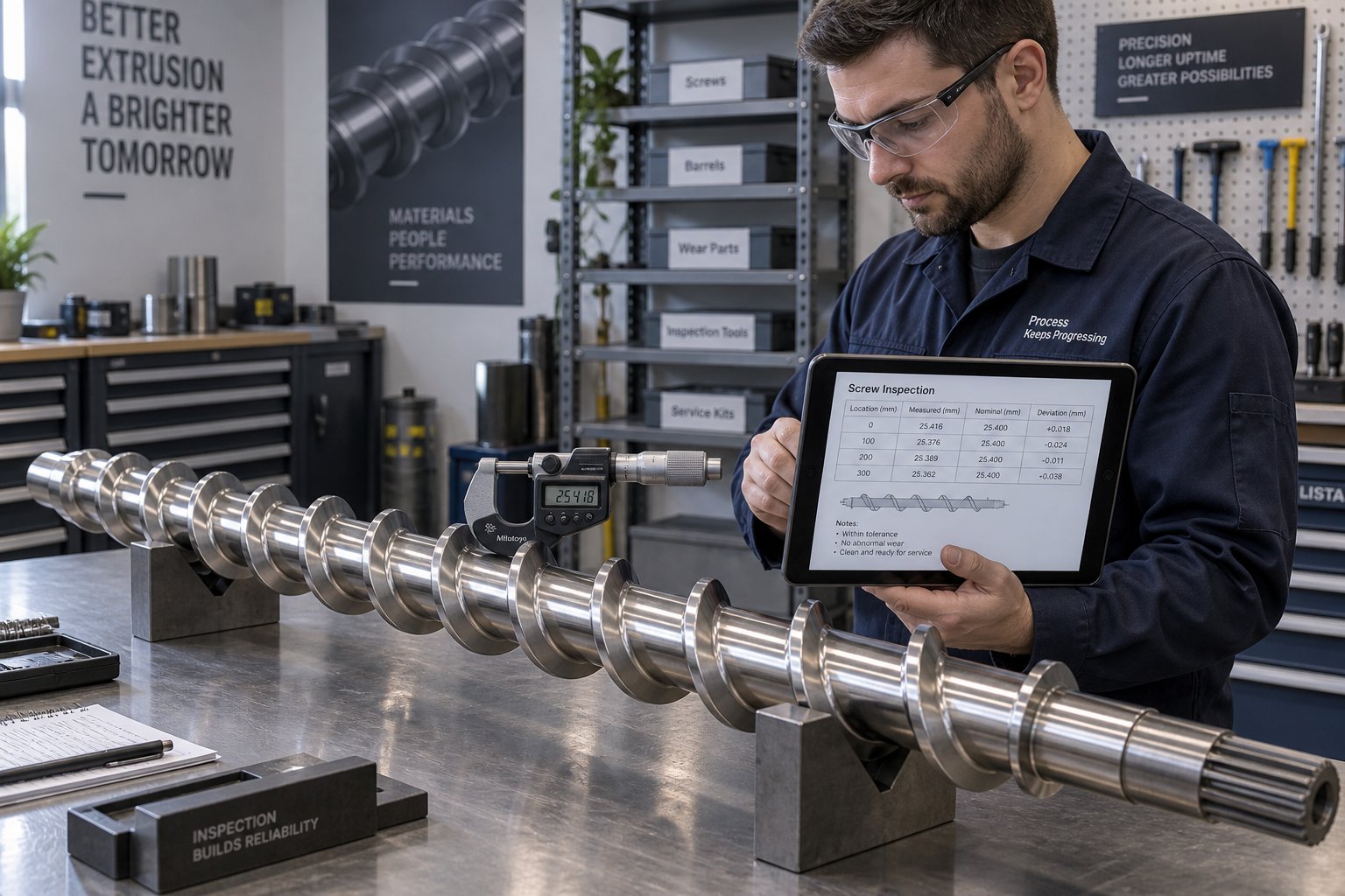
Preventive Maintenance to Maximize Replacement Screw Longevity
You've invested in the right metallurgy, verified the barrel bore, commissioned the new screw with a proper break-in, and documented your baseline process parameters. That investment only pays dividends if you protect it going forward. The difference between a screw that lasts three years and one that lasts five often comes down to what happens between replacement events — the routine inspections, operating disciplines, and data tracking that most plants acknowledge as important but struggle to execute consistently.
A structured preventive maintenance program doesn't just extend screw life. It transforms the next extruder screw replacement from a reactive emergency — scrambling for quotes while the line bleeds money — into a planned, budgeted event scheduled weeks or months in advance. That shift alone can save more than the cost of the replacement itself.
Building a Screw and Barrel Inspection Schedule
The foundation of any PM program is knowing what to inspect, how often, and what the results should tell you. The specific intervals depend on your resin's abrasiveness, daily throughput volume, and cumulative operating hours — a line running 30% glass-filled nylon around the clock wears components far faster than one processing unfilled LDPE on a single shift. But every operation needs a starting framework, even if you adjust the frequencies as wear trends become clear.
The table below provides a baseline schedule. Treat it as a starting point and tighten intervals for aggressive applications or loosen them for mild ones once your own wear data supports the change.
| Inspection Task | Recommended Frequency | What to Look For |
|---|---|---|
| Screw pull for dimensional measurement | Every 6 months (filled resins) / Every 12 months (unfilled resins) | Flight OD reduction, root diameter erosion, flight width loss, surface condition (pitting, scoring, galling). Compare against baseline measurements recorded at installation. |
| Barrel bore measurement | Every screw pull (concurrent) | Bore diameter enlargement at feed, transition, and metering zones. Check for ovality exceeding 0.05 mm. Compare against OEM nominal bore diameter. |
| Drive alignment verification | Every screw pull and after any drive system maintenance | Coupling wear, shank engagement condition, gearbox output shaft runout. Misalignment accelerates adhesive wear on the screw and barrel from the first rotation. |
| Process parameter trend monitoring | Continuous (daily data logging recommended) | Specific energy consumption (kWh/kg), motor amperage at rated RPM, melt temperature deviation from setpoint, discharge pressure stability, output rate at constant RPM. |
| Non-return valve inspection (injection molding screws) | Every 3 to 6 months depending on resin | Seat wear, ring clearance, check-ring response time. Worn valves cause cushion inconsistency and shot-to-shot variation in injection molding screws and barrels. |
| Visual barrel bore inspection (borescope) | Every screw pull | Scoring, corrosion pitting, liner delamination, deposit buildup in vent zones. Visual data supplements dimensional measurements and reveals damage patterns that numbers alone can miss. |
As Reiloy USA's Preventative Maintenance Handbook emphasizes, a disciplined PM program measures the life of the screw, barrel, and valve for the specific resins being processed. Once wear trends are established — how many operating hours before flight OD drops by a measurable amount, for example — you can predict replacement timing rather than react to failures. That predictability is the entire point. It lets you order components, schedule downtime during planned shutdowns, and budget for the expense months in advance.
Every inspection should generate a documented report with screw OD, barrel ID, calculated diametral clearance, and surface condition at each measurement station. Over time, these reports build a wear history that reveals your actual component life for each application — data that's far more valuable than generic industry averages.
Operating Practices That Extend Screw Life
Inspection catches wear after it happens. The real leverage is in the daily operating habits that slow wear down in the first place. Most of these practices cost nothing to implement — they're simply disciplines that protect the investment you've already made in precision-manufactured components.
- Purge properly at every startup and shutdown. Residual polymer left in the barrel during idle periods degrades thermally, forming carbon deposits that act as abrasive particles during the next run. A high-quality commercial purging compound cleans the screw and barrel far more effectively than regrind or virgin resin, and some grades are designed to seal the system during shutdown to prevent oxidation. Reiloy USA specifically recommends always removing corrosive and filled resins before idling equipment — leaving glass-filled nylon or PVC sitting in a hot barrel is an invitation for both corrosive and abrasive damage.
- Avoid cold starts. Starting screw rotation before the polymer is fully molten subjects the screw and barrel to enormous mechanical loads. Solid polymer wedged between flights and the barrel wall creates localized stress concentrations that can crack nitrided surfaces or strip hardfacing. Davis-Standard recommends a thorough heat-soak period before restart, ensuring that the polymer is completely molten before the screw begins turning. The soak time depends on barrel size and heater watt density — larger systems need longer soaks — so consult your operating manual for specific guidance.
- Monitor barrel zone temperatures to prevent overheating. Consistently running barrel heaters above recommended setpoints doesn't just degrade the resin — it accelerates the thermal fatigue of nitrided and hardfaced screw surfaces. Over time, excessive temperature cycling weakens the bond between the wear-resistant surface layer and the base steel, leading to spalling and premature flight-tip erosion.
- Use appropriate purge compounds between material changes. Switching from a high-temperature engineering resin to a commodity polyolefin without a thorough purge leaves degraded residue on the screw surface that contaminates subsequent runs and can chemically attack the screw's metallurgy. Some CPCs are specifically formulated to cool and shrink, pulling built-up material and carbon away from metal surfaces — a mechanical advantage that virgin resin simply can't replicate.
- Track specific energy consumption as an early wear indicator. Specific energy — kilowatt-hours per kilogram of output — is one of the most sensitive metrics for detecting gradual screw wear. As clearances open up, the motor works harder to push the same amount of polymer, and energy consumption per unit of output creeps upward. A 10 to 15 percent rise above your documented baseline is a strong signal that the screw has entered its wear acceleration phase and inspection should be prioritized.
- Keep feed throat and hopper systems clean. Contamination entering the extruder feed barrel — metal fines from upstream equipment, degraded pellet dust, or foreign objects — inflicts wear that has nothing to do with the resin itself. Magnetic traps, screen packs, and regular hopper cleaning are inexpensive insurance against preventable abrasive damage.
- Maintain proper screw-to-barrel alignment. Misalignment between the gearbox output shaft and the barrel centerline creates a bending moment on the screw that forces flight tips into contact with the barrel wall. This adhesive wear mechanism is entirely avoidable with periodic alignment checks, yet it remains one of the most common causes of premature component failure.
None of these practices require capital investment. They require consistency — which, in most plants, is the harder ask. Building them into standard operating procedures and training operators on the "why" behind each step makes compliance sustainable rather than dependent on individual memory.
Knowing When Your Next Replacement Is Due
Here's where the entire article comes full circle. The diagnostic symptoms covered earlier — declining output at constant RPM, rising melt temperature, increased specific energy consumption, inconsistent product dimensions — aren't just tools for diagnosing a screw that's already failed. They're the same metrics you should be tracking continuously against the baseline you documented during commissioning.
When you installed the new screw, you recorded motor amps, discharge pressure, melt temperature, output rate, and specific energy at optimized operating conditions. Those numbers represent the screw at its best — zero wear, tightest clearances, peak efficiency. Every subsequent reading is a data point on a wear curve. Plot them over time, and you'll see the trajectory long before performance becomes unacceptable.
Proactive monitoring turns replacement from an emergency into a planned event. Instead of discovering at 2 AM on a Thursday that your used twin screw extruder line is producing out-of-spec product because the screws are shot, you're placing a replacement order three months ahead of the projected end-of-life date. You're scheduling the swap during a planned maintenance window. You're providing your supplier with updated barrel bore measurements so the new screw can be manufactured to restore optimal clearance against the barrel's current condition — not its condition five years ago.
The practical benefit is enormous. Planned replacements cost less than emergency ones in every measurable dimension: shorter downtime (because tools, rigging, and personnel are staged in advance), lower scrap (because the cutover happens before product quality deteriorates), better pricing (because you're not paying expedite fees for rush manufacturing), and smarter specification (because you have time to evaluate whether an upgrade makes sense rather than defaulting to a panic reorder of the same design).
Establishing a reliable supplier relationship before the replacement becomes urgent simplifies the entire sourcing process. When your maintenance team already has a working relationship with a manufacturer who holds your screw specifications on file, the lead time from "we need a replacement" to "the screw ships" compresses dramatically. Factory-direct partners like NANHAIYA — who supply custom and replacement screw barrels for both extrusion and injection molding applications — can serve as that proactive resource. Having a supplier who already understands your machine configurations, metallurgy requirements, and dimensional standards eliminates the re-education cycle that costs weeks every time you start from scratch with a new vendor.
The best time to build that relationship is not when the screw is already worn past tolerance. It's now — while the new screw is running well, the process data looks clean, and you have the luxury of evaluating suppliers on capability and quality rather than pure availability. Think of it as the final piece of your maintenance infrastructure: the inspection schedule tells you when to act, the operating practices delay that moment as long as possible, and the supplier relationship ensures that when the moment arrives, you're ready to spec it right — the first time.
Frequently Asked Questions About Extruder Screw Replacement
1. How often should an extruder screw be replaced?
Replacement intervals vary widely based on the resin being processed, filler type, throughput volume, and operating hours. A screw running unfilled polyolefins on a single shift may last several years, while one processing 30% glass-filled nylon around the clock could need replacement within 12 to 18 months. Rather than relying on a fixed schedule, track measurable indicators like specific energy consumption, motor amperage, output rate at constant RPM, and melt temperature deviation. When these metrics drift 10-15% beyond your documented baseline, schedule a screw pull for dimensional inspection to determine whether replacement is warranted.
2. Can you replace an extruder screw without replacing the barrel?
Yes, but only after measuring the barrel bore to confirm it remains within OEM tolerance. If the barrel's internal diameter has enlarged beyond acceptable limits, a new screw will still have excessive clearance, resulting in leakage flow, reduced pumping efficiency, and premature wear on the replacement. Always measure barrel bore diameter at the feed, transition, and metering zones before ordering a new screw. If barrel wear is minimal, replacing the screw alone is cost-effective. If barrel wear is significant, replacing both components as a matched pair delivers the best long-term value.
3. What is the difference between a nitrided and a bimetallic extruder screw?
Nitrided screws use a diffusion process to harden the surface of the base steel, forming a wear-resistant layer suitable for general-purpose and moderate-wear applications such as unfilled PE, PP, or PS. Bimetallic screws feature a specialized alloy layer -- typically tungsten carbide or nickel-based -- applied to the flight surfaces, offering two to five times longer service life in abrasive-filled applications like glass-fiber or mineral-loaded compounds. Bimetallic screws cost more upfront but typically deliver a lower cost per operating hour for demanding applications. Factory-direct suppliers like NANHAIYA can help match the right metallurgy to your specific processing conditions.
4. What happens if you skip the break-in period on a new extruder screw?
Skipping break-in exposes the new screw's microscopic surface irregularities to full operating loads immediately. This concentrates excessive contact pressure on high spots where the flight tips meet the barrel wall, which can trigger galling -- a destructive adhesive wear mechanism where metal surfaces momentarily weld together and tear apart. Once galling begins, it cascades and accelerates further damage. A proper break-in involves starting at 30-50% of normal RPM with an unfilled polymer for two to four hours, then gradually ramping speed in 10-15% increments while monitoring drive torque and melt pressure for stability.
5. How do I measure extruder screw wear accurately?
使用外径千分尺测量螺杆全长每隔一个螺纹的外径,重点关注磨损通常最严重的过渡区和计量区。测量不同角度(0°和90°)螺纹间的根部直径,以检测椭圆度和不对称侵蚀。使用卡尺记录螺纹宽度,并记录螺纹总长度、区域过渡区和混合元件位置。将所有测量结果与原始OEM规格或您记录的安装基准进行比较。一项广泛引用的指南将螺纹间隙超过原始径向公差四倍视为更换阈值,但实际影响取决于树脂粘度和质量要求。
Written by
Nanhaiya Technical Team
Zhoushan Nanhaiya Plastic Machinery Co., Ltd.
The Nanhaiya technical team supports screw and barrel manufacturing projects through application review, technical communication, custom manufacturing coordination, and production and quality control.
Discuss Your Application
Related Articles
More insights on screw barrel technology and plastics processing.
What Your Single Screw Extruder Manufacturer Won't Tell You
Oct 10, 2026
Learn how to evaluate single screw extruder manufacturers with this buyer-focused guide covering specs, configurations, material matching, and a ready-to-use selection checklist.
Read Article
Plastic Extruder Screw Price Demystified: From Steel To Sticker
Oct 10, 2026
What drives plastic extruder screw price? This independent guide breaks down diameter, L/D ratio, metallurgy, order volume, and total cost of ownership factors.
Read Article
What No Supplier Tells You About WPC Decking Making Machines
Oct 6, 2026
Learn how a WPC decking making machine works, compare extruder types, formulations, and production methods, plus get a buyer checklist to evaluate any supplier.
Read ArticleLooking for something else?
Search by material, symptom or product and jump straight to the relevant page.
These are navigation suggestions based on keyword matching — not a quotation, not a delivery commitment, and not a substitute for engineering review. Final specification is confirmed by our engineers against your drawings and processed material.
Need help with screw barrel selection?
Share your machine model, processed material and application. Our team can help with pricing and technical support.