

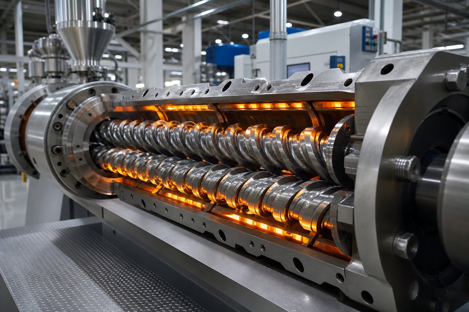
What Is a Double Screw Extruder and How Does It Work
If you have ever searched for a double screw extruder and ended up reading about twin screw extruders, you are not alone. These two terms describe the exact same machine. The difference is purely linguistic, and understanding that early on saves you hours of confusion when comparing equipment specifications or reading technical datasheets.
Double Screw vs Twin Screw — Same Machine, Different Names
Industry engineers and academic publications overwhelmingly use the term "twin screw extruder." So why does "double screw extruder" show up in so many search queries? The answer is straightforward. Manufacturers and buyers across Asia, the Middle East, and parts of Europe translate the concept literally from their native languages, producing "double screw" instead of "twin screw." Both phrases point to the identical piece of equipment — a screw extruder built around two parallel, intermeshing screws rotating inside a heated barrel. Whether you call it a twin-screw extruder or a double screw extruder, you are evaluating the same core technology, the same screw elements, and the same processing principles.
A double screw extruder (twin screw extruder) is a processing machine that uses two co-rotating or counter-rotating intermeshing screws housed within a heated barrel to convey, melt, mix, and shape polymers, food ingredients, pharmaceuticals, and other materials into finished or semi-finished products.
How the Double Screw Extruder Works at a Fundamental Level
Imagine two helical screws placed side by side, their flights meshing together like gears. As they rotate, raw material — pellets, powder, or granules — enters through a feed hopper and gets pulled forward along the barrel. The barrel itself is divided into individually heated zones, each set to a specific temperature. As the material advances, it encounters increasing heat and mechanical shear generated by the intermeshing screw flights. This combination of thermal and mechanical energy melts the material, blends in any additives or fillers, removes trapped air or moisture through venting ports, and finally pushes a homogeneous melt through a die at the discharge end.
The intermeshing geometry is what makes this extrusion extruder fundamentally different from a single-screw design. Because each screw wipes the surface of the other, material cannot stagnate or build up on the barrel walls. This self-wiping action keeps the melt moving uniformly and prevents localized overheating — a critical advantage when processing thermally sensitive compounds.
Why Double Screw Extruders Outperform Single-Screw Designs
A single screw extruder relies on friction between the material, the screw, and the barrel wall to generate forward movement and melting. That works well for simple tasks, but it limits mixing capability and throughput flexibility. A twin screw extruder, by contrast, offers three decisive advantages:
- Superior mixing and homogenization: The intermeshing screws generate high shear forces that break down agglomerates and distribute additives evenly throughout the melt, a capability that single-screw machines simply cannot match.
- Self-wiping capability: Material is continuously scraped off every surface, preventing degradation from extended heat exposure and ensuring consistent melt quality batch after batch.
- Process versatility: Modular screw elements can be rearranged along the shaft to create distinct processing zones — feeding, melting, mixing, venting, and pressurization — all within a single extrusion extruder platform. This modularity lets operators tailor the screw profile to each specific material and application.
These strengths explain why twin screw extruders dominate applications ranging from polymer compounding and masterbatch production to pharmaceutical hot melt extrusion and food processing. Yet the real performance differences between machines often come down to something most buyers overlook: the specific configuration of the twin screw system and the technical specifications behind it.
Co-Rotating vs Counter-Rotating Twin Screw Configurations
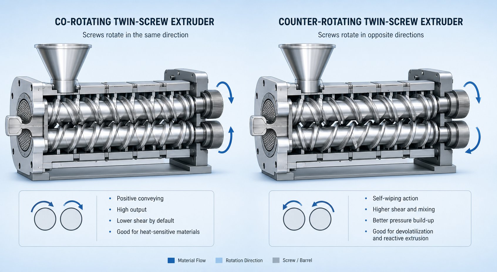
Every double screw extruder falls into one of two fundamental categories based on a single question: do the twin screws rotate in the same direction, or in opposite directions? This distinction might sound minor, but it completely reshapes the flow field inside the barrel, the shear forces acting on the material, and ultimately the applications each machine can handle. Choosing the wrong configuration can mean degraded polymer, inconsistent melt, or a machine that simply cannot deliver the mixing intensity your formulation demands.
Co-Rotating Twin Screw Extruders and Their Strengths
In a co-rotating twin screw extruder, both screws turn in the same direction — typically with fully intermeshing geometry. Picture the material being forcibly handed off from one screw flight to the next at the intermeshing zone. This constant transfer creates intense shear fields both between the screws themselves and between the screw flights and the barrel wall. The result? Outstanding dispersive and distributive mixing that can break down filler agglomerates, achieve uniform pigment distribution, and promote mass transfer during reactive extrusion.
One of the most valuable features of this configuration is its self-wiping capability. Because each screw continuously scrapes the surface of its partner, there are virtually no dead zones inside the barrel. Material cannot stagnate, which keeps the residence time distribution narrow — a critical factor when processing heat-sensitive polymers or running reactions that require precise thermal exposure. The degree of barrel fill can also be controlled independently through starve-feeding, giving operators fine-tuned command over mixing intensity and energy input.
These characteristics make the co-rotating configuration the dominant choice for polymer compounding with inorganic and organic fillers, polymer alloy and blend production, nanocomposite processing, and pharmaceutical hot-melt extrusion. Whenever your process demands high shear, tight residence time control, and the ability to rearrange modular screw elements for different formulations, a co-rotating twin screw extruder is typically the answer.
Counter-Rotating and Conical Configurations Explained
Counter-rotating twin screw extruders flip the script. Here, the two screws rotate in opposite directions, drawing material inward at the intermeshing zone and pushing it forward through compression. This geometry creates a fundamentally different conveying mechanism — one that behaves more like a positive-displacement pump. Material transport depends heavily on screw rotation itself rather than on friction, and the machine naturally operates at a high degree of fill.
The shear stress between the screws is significantly lower compared to co-rotating designs. Instead of intense shear mixing, the counter-rotating configuration relies on compressive and elongational deformation. A calendering effect develops at the intermeshing region, where material undergoes repeated compression and stretching under relatively gentle conditions. This is a major advantage for thermally sensitive materials like rigid PVC, which has a low decomposition temperature and poor melt flow. High shear would generate excessive heat and trigger degradation, but the counter-rotating design keeps temperatures in check through low-speed, high-fill operation.
Within the counter-rotating category, you will encounter two distinct geometries:
- Parallel twin screw extruder: The screws maintain a constant diameter along their full length. This design offers a longer processing path and higher L/D ratios, which provides more time for plasticization — especially important for high-filler-loading applications like PVC with 100 phr calcium carbonate. The larger, more robust screw core also resists wear from abrasive fillers more effectively than conical alternatives.
- Conical twin screw extruder: The screws taper from a larger diameter at the feed end to a smaller diameter at the discharge end. This tapered design creates natural compression as material moves forward, which enhances feeding of bulky or low-density powders. Conical extruders are compact and well-suited to smaller throughput ranges, making them popular for rigid PVC pipe and profile extrusion at moderate production volumes.
The table below gives you a side-by-side view of how these configurations compare across the dimensions that matter most when evaluating a double screw extruder for a specific application:
| Characteristic | Co-Rotating (Parallel) | Counter-Rotating (Parallel) | Counter-Rotating (Conical) |
|---|---|---|---|
| Mixing Intensity | High — strong dispersive and distributive mixing via shear and elongational flow | Moderate — relies on calendering effect and compressive deformation | Moderate — gentle mixing with natural compression from tapered geometry |
| Conveying Mechanism | Drag flow with material transfer between screws; starve-fed operation common | Positive displacement; material drawn in at intermeshing zone under high fill | Positive displacement with progressive compression from taper |
| Shear Level | High | Low to moderate | Low to moderate |
| Self-Wiping Capability | Excellent — fully self-wiping with minimal dead zones | Limited — geometry does not fully self-wipe | Limited — similar to parallel counter-rotating |
| Typical Applications | Polymer compounding, reactive extrusion, nanocomposites, pharmaceutical HME, masterbatch | PVC pipe and profile extrusion, high-filler PVC compounds, sheet production | Rigid PVC pipes and profiles, moderate-volume PVC processing, lab-scale compounding |
| Throughput Range | Wide — from lab-scale (grams/hour) to high-volume production (tons/hour) | Moderate to high — optimized for steady-state extrusion forming | Low to moderate — compact design favors smaller production volumes |
| Thermal Sensitivity Handling | Manageable through screw design and starve-feeding, but inherently higher shear heating | Excellent — low shear and low-speed operation minimize heat generation | Excellent — tapered screws and gentle conveying keep melt temperature low |
When to Choose Each Configuration
The decision between co-rotating and counter-rotating comes down to what your material needs and what your process must achieve. Ask yourself two questions:
- Does the application demand intensive mixing, filler dispersion, or chemical reaction? Choose a co-rotating twin screw extruder. The high shear, self-wiping geometry, and modular screw design give you the flexibility to optimize dispersive and distributive mixing independently.
- Does the application involve a thermally sensitive material like PVC, or does it prioritize stable, low-shear conveying into a forming die? A counter-rotating design — either parallel or conical — is the better fit. The positive-displacement conveying and gentle calendering effect protect the material from shear-induced degradation while delivering consistent output.
For high-filler PVC formulations specifically, the parallel twin screw extruder holds an edge over the conical version. Its longer barrel provides more residence time for plasticization, and the robust screw core withstands the abrasive wear that calcium carbonate and similar fillers impose. Conical configurations, on the other hand, shine when compact footprint and efficient feeding of bulky powders take priority.
Understanding these configuration differences puts you ahead of most buyers who evaluate machines on throughput alone. Yet configuration is only half the picture — the real performance envelope of any double screw extruder is defined by the technical specifications that sit behind the screws, the barrel, and the drive system.
Essential Technical Specifications You Need to Evaluate
Configuration tells you what type of double screw extruder fits your process. Specifications tell you whether a particular machine can actually deliver the throughput, mixing quality, and thermal control your formulation demands. The problem? Most manufacturers lead with headline numbers — maximum output, peak motor power — while burying the parameters that truly define performance. Knowing which specifications to scrutinize, and how they influence each other, separates informed buyers from those who discover limitations only after commissioning.
Understanding L/D Ratio and Screw Diameter Classes
Two numbers anchor every twin screw extruder machine evaluation: screw diameter and L/D ratio. Think of screw diameter as the scale selector. It sets your baseline throughput capacity because volumetric output scales roughly with the cube of the diameter. That means doubling the screw diameter does not just double your output — it increases it by approximately eight times. Industry conventions group diameters into three classes:
- Lab-scale (5 mm to 27 mm): Designed for formulation screening and R&D, processing grams per hour rather than kilograms. These machines conserve expensive experimental materials while still replicating real processing conditions.
- Pilot-scale (27 mm to 50 mm): The bridge between development and production, delivering 5 to 200 kg/hr and producing scale-up data that engineers can trust when configuring larger equipment.
- Production-scale (50 mm to 300+ mm): Built for continuous manufacturing, with throughputs ranging from 200 kg/hr on smaller production units to well over 8,000 kg/hr on large-diameter compounding lines.
The L/D ratio — total screw length divided by diameter — determines your processing real estate. Each functional zone along the barrel (feeding, melting, mixing, venting, pressure buildup) typically occupies one 4D-length barrel segment. A higher L/D ratio means more zones and greater processing flexibility. Most co-rotating double screw extruder machines operate between 32:1 and 68:1, with 40:1 to 48:1 being the sweet spot for complex compounding that involves side-feeding, vacuum devolatilization, and multiple mixing stages. Shorter ratios like 28:1 suit simpler processes with fewer unit operations, while reactive extrusion applications may push beyond 52:1 to provide the residence time that chemical reactions require.
Here is where many buyers stumble: a longer L/D ratio is not automatically better. Every additional barrel segment extends residence time, raises energy consumption, and increases the risk of thermal degradation for heat-sensitive polymers. The right ratio matches the number of processing functions your application actually demands — nothing more.
Torque Density, Screw Speed, and Free Volume
If screw diameter and L/D ratio define the machine's physical envelope, torque density defines how hard it can work within that envelope. Measured in Nm/cm3, torque density quantifies how much mechanical force the gearbox and screw shafts can transmit to the material. It is often the true bottleneck in high-output applications — you can have plenty of motor power, but if the shaft geometry cannot deliver that energy to the screw elements, throughput hits a ceiling.
Modern extruder system classifications based on torque density look like this:
| Torque Density Range | Classification | Typical Applications |
|---|---|---|
| 5 – 10 Nm/cm3 | Standard | Unfilled polymers, color concentrates, low-viscosity blends |
| 10 – 15 Nm/cm3 | High torque | Moderate-fill compounding, engineering thermoplastics |
| 15 – 18+ Nm/cm3 | Ultra-high torque | Highly filled compounds, glass-reinforced materials, reactive extrusion |
Maximum screw speed interacts directly with torque through a fixed relationship: Torque (Nm) = 9550 x kW / RPM. A 200 kW motor geared for 600 RPM delivers identical torque to a 400 kW motor geared for 1,200 RPM. Higher speeds improve shear intensity and material turnover — co-rotating machines can reach 1,200+ RPM — but they demand more robust drive systems and reduce the torque available per revolution. The practical guideline is to run at roughly 80% of continuous torque capacity and 80% of maximum speed, leaving margin for cold-start spikes and process variability.
Free volume — the open space inside the barrel available for material after subtracting the screw element volume — is governed by the Do/Di ratio (outer screw diameter divided by root diameter). A higher Do/Di ratio like 1.71 or 1.80 creates deeper channels with roughly 40% more free volume than a 1.55 design, boosting intake capacity for bulky or low-density feedstocks. The trade-off? A larger channel depth leaves a thinner shaft core, reducing the torque the screw can transmit. Lower Do/Di ratios (1.46 to 1.55) sacrifice volume for mechanical strength — the preferred choice for torque-intensive applications like glass-filled polyamide compounding.
How Specifications Interact to Define Performance
No specification exists in isolation. A higher L/D ratio provides more processing zones, but those additional zones require the gearbox to sustain torque over a longer shaft — increasing mechanical stress and energy consumption. A larger screw diameter dramatically boosts throughput capacity, yet the surface-area-to-volume ratio drops as diameter grows, making barrel heating and cooling less effective at controlling melt temperature. High screw speeds intensify dispersive mixing, but they also reduce residence time and shift more energy input toward mechanical shear rather than thermal conduction.
These interactions mean that evaluating a double screw extruder machine on any single number — maximum throughput, peak RPM, or motor kilowatts — gives an incomplete picture. The real performance envelope emerges from how all these parameters constrain and complement each other for your specific material and process.
Before comparing machines from any manufacturer, request these essential specifications as a baseline:
- Screw diameter and Do/Di ratio
- L/D ratio and number of barrel zones
- Gearbox torque density (Nm/cm3) — continuous rating, not peak
- Maximum and recommended operating screw speed (RPM)
- Motor power (kW) and the geared speed at which it delivers rated torque
- Free volume per unit length
- Available screw element types and modularity options
- Barrel liner material and construction (nitrided, bimetallic, or PM-HIP)
Armed with these numbers, you can compare machines on equal footing — and immediately identify where one extruder system excels and where another falls short for your application. Yet even perfectly matched specifications only define what the machine can do. What it actually does to your material depends on something far more nuanced: how the modular screw elements are arranged along the barrel to create distinct processing zones.
Screw Profile Design and Modular Processing Zones
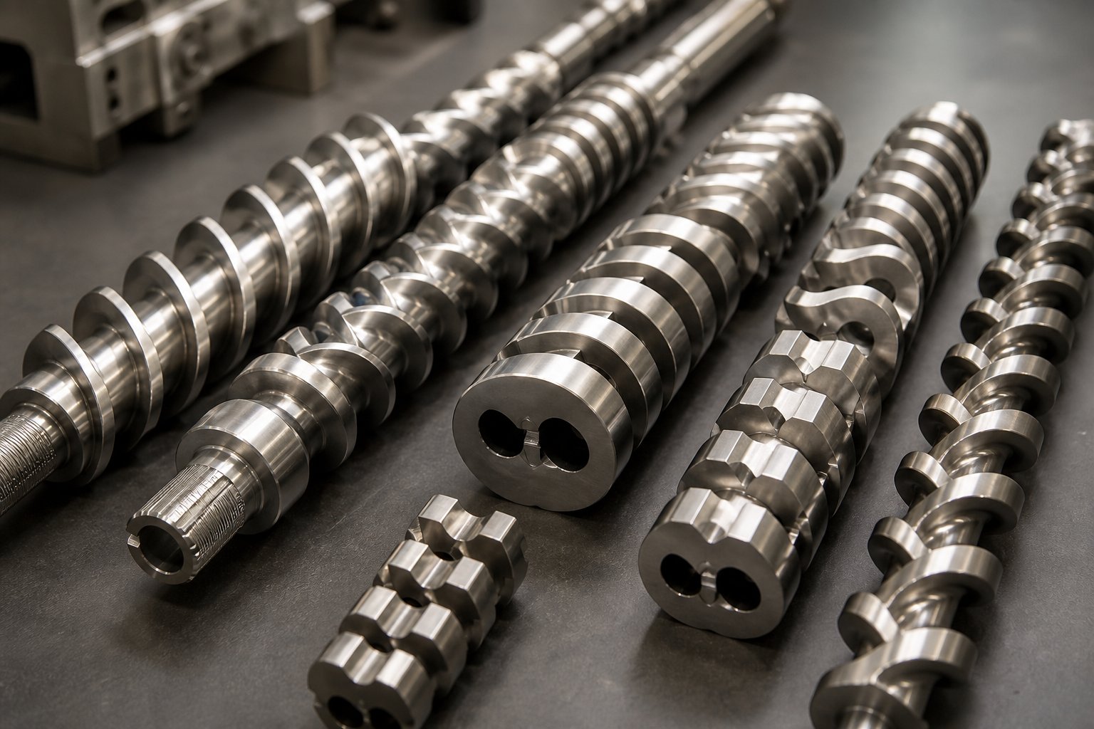
Here is what separates a well-performing double screw extruder from one that produces inconsistent output: the arrangement of modular screw elements along the shaft. The extruder screw in a twin screw machine is not a single machined piece. It is a carefully sequenced assembly of individual elements — each with a specific geometry and a specific job — slid onto a splined shaft like building blocks. Change the order of these blocks, swap one element type for another, and you fundamentally alter how the material is transported, melted, mixed, and pressurized. This modularity is the single greatest advantage of twin screw technology, and it is the area where most technical literature falls short.
The Five Processing Zones in a Twin Screw Barrel
Every plastic extruder screw profile, regardless of application, is organized into functional zones. Each zone performs a distinct transformation on the material. Think of them as stages in a manufacturing line, arranged in sequence from the feed hopper to the die. The material must pass through each stage in order, and the screw elements within each zone are selected specifically for that stage's objective.
- Feeding zone: Raw material — pellets, powder, fibers, or liquids — enters the barrel through the feed hopper and must be captured and conveyed forward reliably. This zone uses large-lead forward conveying elements (often SK-type) with deep channels to maximize free volume and accommodate bulky or low-density feedstock. The goal is smooth intake without compaction or bridging. If downstream side-feeders introduce additional materials like glass fiber or mineral fillers, those ports also require their own feeding zone with high free-volume elements to accommodate the new material without overfilling.
- Melting and plasticating zone: The material transitions from a solid state to a viscous melt. This zone begins with low-lead conveying elements that compress the material and build pressure, then introduces kneading blocks that convert mechanical energy into heat through shear. Two heat sources drive melting: the barrel heaters provide conductive thermal energy, while the screw elements introduce shear heating — and the latter is typically the dominant source. Effective melting requires distributing this energy input over a sufficient axial length, rather than concentrating it in a short, aggressive section that would spike material temperature far above the setpoint.
- Mixing zone (distributive and dispersive): With the material now molten, this zone ensures additives, fillers, and pigments are uniformly incorporated. Dispersive mixing breaks down agglomerates using high shear stress — achieved through wide kneading blocks and tight clearances. Distributive mixing spreads the dispersed phase evenly throughout the melt using flow-splitting elements. Most compounding profiles require both types, often in sequence.
- Venting and devolatilization zone: Moisture, trapped air, and volatile byproducts must be removed before the melt reaches the die. Upstream of the vent port, reverse elements or reverse kneading blocks create a melt seal that builds high pressure, preventing gas from escaping backward. At the vent port itself, large-lead conveying elements reduce the degree of barrel fill and create a thin melt layer with maximum exposed surface area — ideal for volatile extraction under atmospheric or vacuum conditions.
- Pressurization and pumping zone: The final section must build enough pressure to push the melt through the die at a consistent flow rate. Screw lead decreases progressively in this zone, compressing the melt and generating the required discharge pressure. Single-flight elements are sometimes used here to enhance forward pumping capability and prevent melt from surging backward.
Kneading Blocks, Conveying Elements, and Specialized Discs
The elements that populate these zones fall into three broad families, and understanding how each one works gives you real control over the plastic extrusion screw profile.
Conveying elements form the backbone of every screw configuration. Forward-pitch conveying elements move material toward the die, and their lead (the axial distance per revolution) determines how aggressively they do it. High-lead elements transport material quickly with low fill and low shear — perfect for feeding zones and vent sections. Low-lead elements slow the material, increase fill ratio, and build pressure — essential for the transition into melting and for the final pumping zone. Reverse-pitch conveying elements use left-hand threads to push material backward, creating localized pressure peaks and extending residence time. These are placed strategically before vent ports to form melt seals or after mixing sections to intensify the upstream shear.
Kneading blocks are the primary mixing elements and arguably the most influential components in any extruder screw design. Each kneading block consists of a series of elliptical discs stacked on the shaft at a specific stagger angle — the angular offset between adjacent discs. The stagger angle is the single most important parameter controlling mixing behavior:
| Stagger Angle | Mixing Character | Conveying Effect | Typical Use |
|---|---|---|---|
| 30 degrees | Mild distributive mixing | Strong forward conveying | Preliminary blending, gentle incorporation of heat-sensitive additives |
| 45 degrees | Balanced dispersive and distributive mixing | Moderate forward conveying | General-purpose compounding, pigment dispersion |
| 60 degrees | Strong dispersive mixing | Weak forward conveying | Breaking agglomerates, intensive filler dispersion |
| 90 degrees (neutral) | Maximum shear input | No net conveying — material stalls | Aggressive melting, pressure balancing before vent zones |
| Negative (reverse) | High shear with backflow | Backward — creates melt seal | Upstream of vent ports, residence time extension for reactive extrusion |
Disc width adds another layer of control. Narrow discs (small axial thickness) create more tip clearances per unit length, resulting in a higher frequency of material exchange between discs and stronger distributive mixing. Wide discs reduce this exchange frequency, favoring dispersive mixing through sustained shear exposure. In practice, engineers combine both disc widths within a single kneading block section to balance both mixing modes.
Specialized elements fill niche roles that standard conveying and kneading blocks cannot. Toothed mixing elements (TME) feature rows of teeth that divide and recombine the melt stream repeatedly, producing excellent distributive mixing at very low shear — ideal for color masterbatch applications where pigment distribution must be uniform without degrading the carrier resin. Cam-type mixing elements generate elongational flow rather than pure shear, improving both dispersive and distributive mixing in engineering plastics and high-performance compounds. Blister rings and dam elements force the melt through a narrow annular gap, creating a sharp pressure drop that acts as a seal between processing zones — particularly useful for isolating vacuum vent sections from upstream high-pressure regions.
How Element Arrangement Controls Material Transformation
Knowing what each element does is only the starting point. The real craft lies in sequencing them along the shaft. As an NC State Extension publication on screw profile design notes, configuring a screw is a blend of art and science — no single gold-standard arrangement works for every material, because each polymer and filler combination exhibits unique flow behavior under heat and shear.
Several principles, however, apply universally:
- Distribute energy input over length: Concentrating all kneading blocks in one short section produces a violent temperature spike. Instead, interspersing kneading elements with forward conveying elements spreads the shear energy over a longer axial distance, keeping material temperature closer to the setpoint while still achieving thorough melting and mixing.
- Match element intensity to material state: Aggressive 60-degree or 90-degree kneading blocks are most effective after the material has already partially melted. Placing them too early, before sufficient softening has occurred, wastes energy on solid compaction rather than productive mixing.
- Control residence time through restriction: Reverse elements and reverse kneading blocks are powerful tools, but overusing them floods the upstream zones, raises fill level excessively, and can trigger torque spikes. Their length should generally remain shorter than one screw diameter to avoid dangerous pressure peaks.
- Protect the vent zone: The devolatilization section must maintain a low degree of fill so volatiles can escape from the melt surface. A melt seal (reverse element or dam ring) immediately upstream of the vent port prevents high-pressure melt from shooting through the vent, while large-lead conveying elements at the vent port itself maximize exposed surface area.
Every change to the screw profile — swapping a 45-degree kneading block for a 60-degree one, adding an extra reverse element before the vent, or extending the pressurization zone with lower-lead conveying elements — alters the residence time distribution, shear history, and melt temperature profile of the entire process. These three variables collectively determine whether the final product meets its mechanical, optical, and thermal specifications. Getting the screw profile right is, without exaggeration, the single most impactful engineering decision in any twin screw extrusion operation.
Yet even a perfectly designed screw profile can underperform if the process parameters surrounding it — screw speed, feed rate, barrel temperatures, and vacuum levels — are not dialed in to complement the element arrangement.
Critical Process Parameters That Drive Product Quality
A perfectly sequenced screw profile is only half the equation. The other half — the one that determines whether your melt is pristine or degraded, whether your filler is fully dispersed or clumped — lies in the process parameters you dial into the machine. Screw speed, feed rate, and barrel temperature are often treated as independent knobs, but in a twin screw extrusion process they are deeply coupled. Adjust one, and the other two shift in consequence. Understanding how these parameters interact, and measuring their combined effect through a single unifying metric, is what separates operators who chase problems from those who prevent them.
Screw Speed, Feed Rate, and Specific Energy
Imagine raising screw speed from 400 to 800 RPM. Intuitively, you might expect throughput to double. In practice, though, co-rotating twin screw extruders almost always run in starve-fed mode — meaning a gravimetric feeder, not the screw speed, controls how much material enters the barrel. This decoupling is a fundamental advantage of starve feeding: it lets you increase screw RPM to intensify shear and mixing without automatically pushing more material through the system. The result is independent control over two variables that single-screw machines lock together.
Raising screw speed has a clear trade-off, however. Greater RPM increases the mechanical energy input inside kneading and mixing zones, which raises melt temperature. At the same time, material moves through the barrel faster, reducing the average residence time. Research on twin screw compounding parameters confirms that screw speed has a relatively small influence on residence time compared to feed rate — but its impact on melt temperature is substantial. Higher speeds generate more viscous dissipation in every fully filled element, and that heat accumulates along the barrel length.
The metric that ties mechanical and thermal energy input into a single number is specific energy, expressed in kWh/kg (or equivalently kJ/kg). It represents the total energy the extruder delivers to each kilogram of material. In twin screw extrusion, the dominant energy source is shear from the rotating screws rather than conductive heat from barrel heaters. Specific energy is calculated from motor torque, screw speed, and throughput — and it becomes the master variable for scale-up. Laboratory trials on an 11 mm compounder, for example, yielded a specific energy of approximately 559 kJ/kg. When scaling to a 16 mm machine, matching that specific energy — rather than simply matching RPM — produced comparable residence times and melt quality.
Feed rate plays a complementary role. A higher throughput at constant screw speed reduces both the average residence time and the width of the residence time distribution, because the barrel fills more completely and material spends less time in partially filled conveying sections. Conversely, lowering the feed rate extends residence time, increases specific energy input per kilogram, and intensifies the mixing experience. For highly dispersive applications like color masterbatch for thin films, deliberately reducing the feed rate while maintaining high RPM gives the material more exposure to kneading elements — at the cost of lower throughput.
Barrel Zone Temperature Profile Management
While screw speed and feed rate govern the mechanical side of energy input, the barrel temperature profile shapes the thermal environment the material travels through. Each barrel zone is individually heated — and critically, individually cooled — to maintain a setpoint that supports the specific transformation happening in that zone. A typical profile for a polyolefin compound might start with moderate temperatures in the feed section (to prevent premature melting and bridging), ramp up through the melting zone, hold steady or drop slightly through the mixing zones, and then reduce further toward the die to lower melt viscosity for stable strand formation.
The barrel temperature profile must complement the mechanical shear profile rather than fight against it. If barrel setpoints are too low in the melting zone, the screw must do all the work — torque climbs, melt temperature overshoots the setpoint due to excessive viscous dissipation, and the risk of torque-limited shutdown rises. If setpoints are too high, the polymer softens before it reaches the kneading blocks, reducing the shear stress those elements can impart and weakening dispersive mixing. In the words of experienced compounding engineers, the screw extrusion process works best when barrel heaters gently assist melting and the screws deliver precise, controlled shear — not when one energy source overwhelms the other.
An often-overlooked detail: as twin screw extruders scale up in diameter, the barrel surface-area-to-volume ratio decreases. A larger machine has proportionally less barrel wall area per unit of material volume, so the rate of heat transfer — both heating and cooling — diminishes with increasing barrel diameter. This means that screw-generated shear heating becomes even more dominant on production-scale machines, and barrel temperature setpoints function more as gentle guides than as primary energy sources.
Devolatilization and Residence Time Distribution
Removing moisture, trapped air, and volatile byproducts is one of the operations where twin screw extruders genuinely have no equal. The pressure profile inside the barrel can be engineered to drop to zero — or even below atmospheric under vacuum — at specific vent ports, exposing thin layers of melt to conditions that pull volatiles out of solution. Devolatilization efficiency depends on three factors: the surface area of the melt exposed under the vent, the residence time the melt spends in the vent zone, and the frequency of surface renewal as the screws turn over fresh melt layers.
Increasing screw speed improves devolatilization by creating smaller melt pools with greater exposed surface area and by renewing those surfaces more rapidly. Decreasing feed rate helps too, because it lowers the degree of fill in the vent section, spreading the melt into thinner films. For aggressive volatile removal — stripping unreacted monomer from a reactor discharge, for instance — multiple sequential vents with vacuum can be arranged along the barrel. Each vent stage reduces the residual volatile concentration further, achieving removal rates that batch processing simply cannot match.
Yet the single most misunderstood parameter in this discussion is not average residence time — it is the distribution of residence times across all material particles.
Residence time distribution, not just average residence time, determines the degradation risk for thermally sensitive materials. Two screw profiles may deliver the same average residence time, but if one produces a wider distribution — meaning some fraction of the material dwells far longer in high-temperature zones — that profile will cause measurably more thermal degradation, discoloration, and molecular weight loss.
Broader distributions arise from excessive backmixing (too many reverse elements), dead zones in poorly wiped barrel regions, or overly starved conveying sections where material tumbles slowly rather than advancing steadily. Narrowing the distribution requires matching feed rate to screw speed so that conveying sections maintain consistent fill levels, selecting kneading block configurations that promote plug-flow behavior, and verifying that no element arrangement creates unintended recirculation. Monitoring residence time distribution through tracer studies — injecting a colored marker and tracking its emergence at the die — is one of the most valuable diagnostic tools available to operators of twin screw extruders.
These process parameters — screw speed, feed rate, barrel temperature profile, and vacuum level — collectively define the specific energy and residence time distribution that every particle of material experiences. Dialing them in correctly determines not just whether the product meets specification, but how much of each production run falls within that specification window. The real payoff, however, comes when you connect these process parameters to the applications they serve — because each industry and each material imposes a unique set of demands on the double screw extruder, and matching machine capabilities to those demands is where informed selection begins.
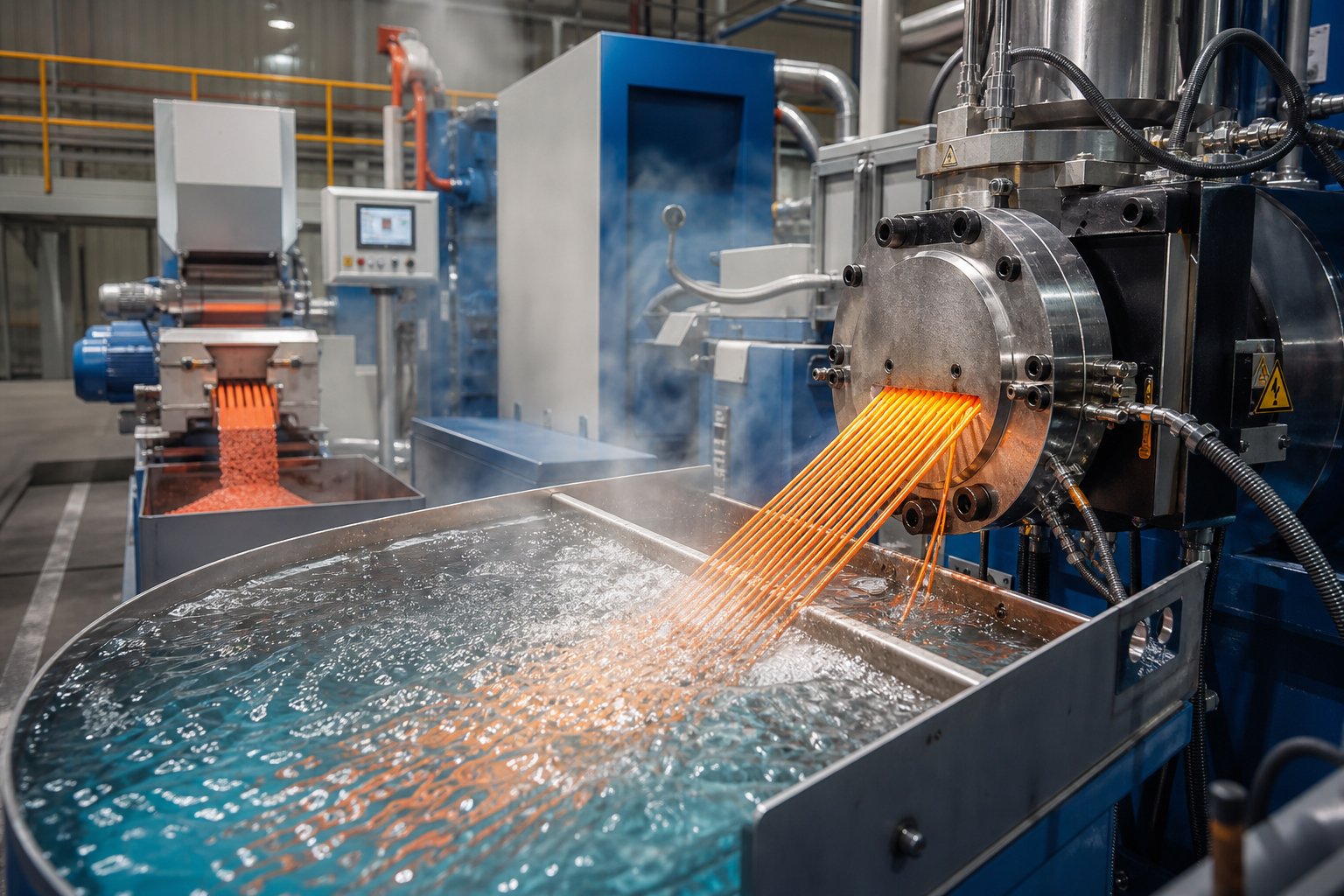
Industry Applications and Why Double Screw Extruders Excel
Specific energy, residence time distribution, barrel temperature profiles — these parameters do not exist in a vacuum. They exist because different industries impose wildly different demands on the double screw extruder, and each application stresses the machine in its own way. Listing industries that use twin screw technology is easy. Explaining why these machines outperform every alternative for each specific application — connecting processing challenges to machine capabilities — is where the real value lies.
Polymer Compounding, Masterbatch, and Recycling
Polymer compounding is the application that made the compounding twin screw extruder indispensable. When you blend a base resin like polypropylene or nylon with glass fibers, mineral fillers, flame retardants, or impact modifiers, you face a fundamental challenge: these additives arrive as agglomerates — clumps of particles held together by surface forces. Dispersive mixing must generate enough shear stress to overcome those forces and break the agglomerates down to primary particle size. Distributive mixing must then spread those particles uniformly throughout the melt. A twin screw compounding extruder delivers both mixing modes simultaneously through its modular kneading block arrangement — something single-screw machines and batch mixers simply cannot replicate with the same precision or throughput.
Consider a glass-fiber-reinforced polyamide compound. The extruder must melt the PA66 at 270 to 300 degrees Celsius, incorporate 30 to 50 percent glass fiber through a downstream side feeder without breaking the fibers to useless lengths, and devolatilize residual moisture that would otherwise cause hydrolysis. A co-rotating compounding extruder handles all of this in a single continuous pass, with screw elements tailored zone-by-zone: gentle large-lead conveying elements at the fiber inlet to minimize breakage, followed by mild distributive mixing elements that spread fibers without excessive shear.
Masterbatch production raises the bar even further. Imagine producing a red color masterbatch for blown film applications. A single speck of undispersed pigment — invisible in a pellet — becomes a glaring defect when that pellet is diluted 25:1 into a film just 25 microns thick. The twin screw extruder plastic processing line for masterbatch demands extreme distributive mixing: narrow-disc kneading blocks at 30-degree stagger angles, toothed mixing elements that split and recombine the melt stream dozens of times per second, and precise temperature control that prevents the carrier resin from degrading during prolonged mixing. Color consistency batch to batch depends entirely on how repeatable the screw profile and process parameters remain.
Plastic recycling presents a different kind of challenge — not precision, but tolerance. Post-consumer recycled feedstock arrives contaminated with moisture, paper labels, adhesive residues, mixed polymer fractions, and residual odors. The double screw extruder handles this chaos through a combination of capabilities that no other platform offers in a single pass:
- High contamination tolerance: The self-wiping screw geometry prevents degraded material from accumulating on barrel walls, even when processing mixed-polymer streams with inconsistent melt viscosity.
- Multi-stage devolatilization: Sequential atmospheric and vacuum vent ports strip moisture, volatiles, and odor-causing compounds from the melt, improving the mechanical and sensory properties of recycled pellets.
- Flexible feed accommodation: Starve-fed operation absorbs variations in bulk density and particle size that would choke a flood-fed single-screw machine.
A polymer extruder designed for virgin resin compounding can often be reconfigured for recycling applications simply by rearranging the modular screw elements — adding extra vent sections, extending the melting zone, or incorporating melt filtration between the barrel and die. This adaptability makes the twin screw platform the workhorse of circular plastics initiatives worldwide.
Pharmaceutical, Food, and Reactive Extrusion Applications
Beyond plastics, the double screw extruder has carved out critical roles in industries where process control is not just desirable — it is regulated.
In pharmaceutical manufacturing, hot-melt extrusion (HME) uses a co-rotating hot melt extruder to dissolve poorly soluble active pharmaceutical ingredients (APIs) into a polymer carrier matrix, creating amorphous solid dispersions that dramatically improve drug bioavailability. The challenge? APIs are expensive, thermally fragile, and require precisely controlled shear to achieve molecular-level solubilization without degradation. The twin screw platform excels here because its narrow residence time distribution — a direct consequence of the self-wiping geometry — ensures that every particle of API experiences virtually identical thermal and mechanical history. Barrel temperature profiles can be set within plus or minus one degree Celsius per zone, and the modular screw design lets formulators adjust mixing intensity without altering the thermal profile. The result is consistent drug loading and dissolution performance from the first gram to the last.
Food processing leverages many of the same capabilities for entirely different raw materials. When producing extruded snacks, breakfast cereals, or textured plant proteins, the twin screw extruder must deliver precise thermal-mechanical energy input to gelatinize starch, denature proteins, and create the expanded, porous structures that define product texture. Starch gelatinization requires a specific window of temperature, moisture, and shear — too little energy produces a dense, undercooked product, while too much destroys the cellular structure that gives extruded snacks their crunch. The ability to independently control screw speed, feed rate, and barrel temperature in a co-rotating machine gives food engineers the fine-grained control needed to hit that window consistently at production scale.
Reactive extrusion pushes the machine into the role of a continuous chemical reactor. In-situ polymerization, grafting reactions, and controlled degradation of polylactic acid all require tightly managed residence time, temperature, and mixing to achieve target molecular weight and conversion. The twin screw barrel becomes a flow reactor where screw elements define reaction zones, reverse elements control hold-up time, and vent ports remove reaction byproducts. Compared to batch reactors, the twin screw platform delivers orders-of-magnitude improvements in heat transfer efficiency and mixing uniformity — and it does so continuously, eliminating the batch-to-batch variability that plagues traditional reactor vessels.
How Material Properties Influence Extruder Selection
Every application discussed above is ultimately governed by the physical and chemical properties of the material being processed. Four material characteristics have the greatest influence on extruder configuration and operating parameters:
- Melt viscosity: High-viscosity engineering plastics like polycarbonate demand high torque density and robust gearboxes. Low-viscosity materials like certain waxes or low-MW polyethylenes require tighter screw clearances to maintain pressure buildup and prevent backflow through the intermeshing zone.
- Thermal sensitivity: PVC, certain biopolymers, and many APIs begin degrading within a narrow temperature window. These materials favor low-shear configurations (counter-rotating for PVC, gentle co-rotating profiles for pharmaceuticals) and demand narrow residence time distributions.
- Abrasiveness: Glass fibers, calcium carbonate at high loadings, and titanium dioxide accelerate wear on screw flights and barrel bore surfaces. Applications with abrasive fillers drive the selection of hardened barrel liners, wear-resistant screw element coatings, and shortened maintenance intervals.
- Hygroscopic behavior: Nylon, PET, and polycarbonate absorb atmospheric moisture rapidly. Processing these materials without thorough pre-drying — or without effective vacuum devolatilization along the barrel — produces hydrolytic degradation, bubbles, and catastrophic loss of mechanical properties.
The table below maps each major application type to the specific double screw extruder capabilities it demands, giving you a practical framework for matching machine features to processing reality:
| Application | Primary Processing Challenge | Critical Extruder Capabilities Required | Preferred Configuration |
|---|---|---|---|
| Polymer compounding | Dispersing fillers, fibers, and additives uniformly into base resin | High dispersive and distributive mixing; side-feeding capability; high torque density for filled systems | Co-rotating parallel |
| Masterbatch production | Achieving speck-free pigment dispersion at high letdown ratios | Intensive distributive mixing (narrow-disc kneading, TME elements); precise temperature control; batch-to-batch repeatability | Co-rotating parallel |
| Plastic recycling | Handling contaminated, variable-quality feedstock; removing volatiles and odors | Multi-stage devolatilization (atmospheric + vacuum vents); contamination tolerance; flexible feeding; melt filtration compatibility | Co-rotating parallel |
| Pharmaceutical HME | Solubilizing thermally sensitive APIs in polymer carriers without degradation | Narrow residence time distribution; plus or minus 1 degree C zone temperature accuracy; gentle, controlled shear; GMP-compliant design | Co-rotating parallel (small diameter, lab to pilot scale) |
| Food processing | Precise thermal-mechanical energy for starch gelatinization and protein texturization | Independent control of screw speed, feed rate, and barrel temperature; food-grade barrel and screw materials; steam injection capability | Co-rotating parallel |
| Reactive extrusion | Controlling residence time and temperature for in-situ polymerization or grafting reactions | Long L/D ratio (48:1+); multiple injection and venting ports; reverse elements for residence time control; high-torque drive for viscosity buildup | Co-rotating parallel |
| PVC pipe and profile extrusion | Processing thermally sensitive PVC without shear-induced degradation | Low-shear, positive-displacement conveying; low-speed operation; precise melt temperature control | Counter-rotating (parallel or conical) |
You will notice a clear pattern in this table: co-rotating parallel configurations dominate nearly every application except PVC and a handful of other shear-sensitive forming operations. This is not coincidence — it reflects the fundamental superiority of the co-rotating geometry for mixing-intensive processes, and it explains why the co-rotating polymer extruder represents the vast majority of new twin screw installations globally.
Selecting the right application match, however, is only the beginning of the ownership journey. Even the best-matched extruder will eventually encounter wear, fouling, and operational drift — realities that bring us to the question most buyers forget to ask before purchase: how do you keep this machine running at peak performance year after year?
Maintenance, Troubleshooting, and Extending Equipment Life
A double screw extruder is a capital investment engineered to run for 15 to 20 years — but only if maintenance keeps pace with wear. The reality? Most production teams invest heavily in screw profile optimization and process parameter tuning, then treat maintenance as an afterthought until throughput drops or pellet quality visibly deteriorates. By that point, the extruder screw and barrel have already lost critical dimensions, and the cost to recover is far higher than the cost of preventing the damage in the first place.
Preventive Maintenance Schedules and Wear Indicators
Structured preventive maintenance eliminates the guesswork. Rather than waiting for a failure to announce itself — a torque spike, a strange noise, a sudden drop in output — a schedule-based approach catches degradation early, when corrective action is still inexpensive. The checklist below organizes the most critical tasks by frequency:
- Daily: Clean the feed hopper and throat to prevent material bridging and contamination. Check barrel zone temperatures, melt pressure, motor load, and screw speed for deviations from baseline. Inspect barrel joints, die head, and gearbox for material or oil leaks. Monitor pellet appearance and strand quality for early signs of melt inconsistency.
- Weekly: Clean the die plate, screen changer, and melt passages to remove carbonized residue. Verify feeder calibration and feeding stability using known weights. Inspect pelletizer blades and replace if dull. Confirm cooling water flow rates and temperatures across all barrel zones.
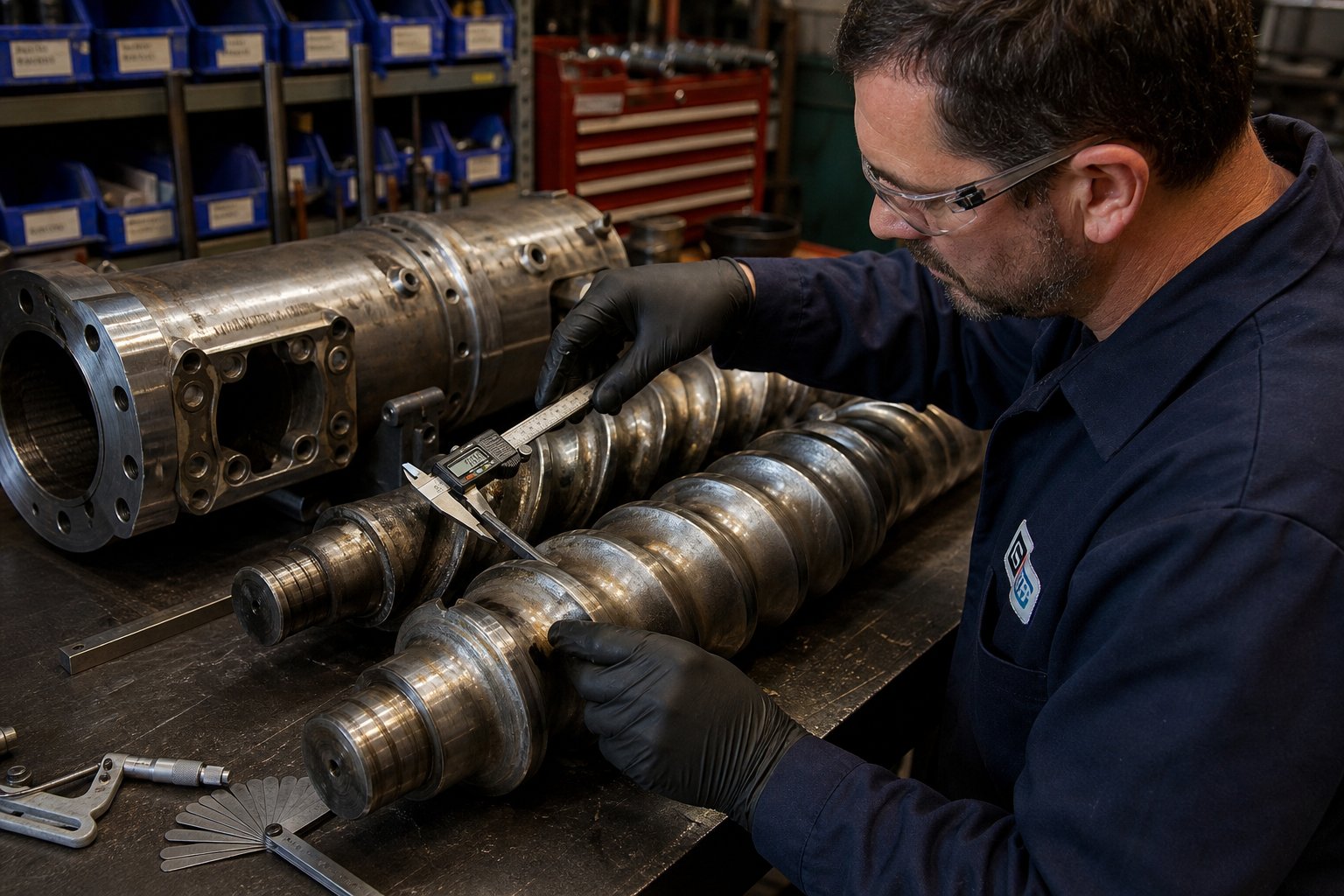
- Scheduled shutdown (monthly to quarterly): Measure screw flight-to-barrel clearance at multiple points along the barrel using feeler gauges — once the gap exceeds 0.3 to 0.5 mm (depending on screw diameter), mixing efficiency and pressure-generation capability drop significantly. Inspect the twin screw and barrel bore surfaces for scoring, corrosion, or uneven wear patterns. Calibrate all thermocouples and pressure transducers. Check screw shaft alignment and concentricity. Perform a full gearbox inspection: change the oil every 2,000 to 3,000 operating hours, inspect gear teeth for pitting, and examine the magnetic drain plug for metal shavings that signal bearing or gear wear.
Wear indicators rarely announce themselves dramatically. Instead, you will notice gradual shifts: throughput declining at the same screw speed and feed rate, motor amperage creeping upward to maintain output, melt temperature drifting higher despite unchanged barrel setpoints, or pellet quality losing consistency batch to batch. Any of these trends, tracked over weeks in a maintenance logbook, reveals component degradation long before a catastrophic failure occurs.
Troubleshooting Common Operational Issues
Even with a rigorous maintenance program, operational problems surface during production. Recognizing the pattern quickly is what separates a 30-minute correction from an eight-hour shutdown.
Surging output — oscillating melt pressure and inconsistent strand diameter — is the most common complaint. The usual culprits are inconsistent feeding (material bridging in the hopper or a drifting gravimetric feeder), air entrapment in the feed throat, or a partially blocked screen pack. Start at the feed end: break up any bridge, recalibrate the feeder, and verify that the feed throat cooling jacket holds 20 to 40 degrees Celsius to prevent premature melting.
Torque spikes point to a sudden increase in melt viscosity or a mechanical restriction. A cold barrel zone that fails to heat causes unmelted material to jam against kneading blocks. A blocked die or collapsed screen raises discharge pressure until the gearbox protests. Check heater band continuity with a multimeter, inspect the die for polymer buildup, and confirm that barrel temperatures match setpoints.
Inconsistent melt temperature often traces back to a failed thermocouple reading low — causing the heater to run continuously and overshoot — or a fouled cooling water jacket that can no longer remove heat effectively. Descale cooling channels every six months, and cross-check thermocouple readings against a calibrated handheld instrument at least quarterly.
Vent flow issues — melt shooting through the vent port or insufficient volatile removal — indicate a broken melt seal upstream of the vent. Inspect the reverse element or reverse kneading block that forms that seal. If the element is worn and no longer creating adequate backpressure, the melt seal fails and volatiles escape upstream rather than through the vent opening.
How Abrasive Materials Accelerate Barrel and Screw Wear
Not all wear is created equal. Processing unfilled polyolefins, a barrel extruder might run for years before screw elements show measurable degradation. Introduce glass fiber at 30 percent loading, calcium carbonate at high concentrations, or titanium dioxide as a pigment filler, and the wear timeline compresses dramatically — from years to months.
Abrasive fillers attack in two ways. First, they erode screw flight tips and kneading block edges, widening the clearance between the screw and the barrel wall. As clearance grows, the screws lose their ability to generate pressure and wipe efficiently, which reduces mixing quality and throughput. Second, hard particles score the barrel bore itself, creating grooves that channel material flow unevenly and accelerate further erosion. For a 75 mm extruder processing filled compounds, screw and barrel components may require replacement or refurbishment every two to three years — a significant recurring cost if you are sourcing generic components that wear at standard rates.
This is precisely where the quality of replacement twin screw and barrel components becomes a cost-of-ownership decision rather than a purchasing decision. Bimetallic barrel liners, nitrided screw surfaces, and powder metallurgy HIP coatings extend service life substantially in high-wear environments. Manufacturers like NANHAIYA, which specializes in custom parallel twin screw barrels for compounding, pelletizing, recycling, and masterbatch applications, engineer their barrel solutions specifically for these demanding conditions. Sourcing barrels designed to resist abrasive wear from the outset — rather than replacing standard components at accelerated intervals — reduces total cost of ownership and keeps unplanned downtime to a minimum.
Tracking wear systematically closes the loop. Record screw flight clearance measurements at every scheduled shutdown, plot them over time, and you will see a wear curve that predicts when replacement becomes necessary — not next week, but months in advance. That predictability transforms maintenance from a reactive headache into a planned line item, and it keeps your double screw extruder producing at its engineered capacity for the full span of its service life.
Maintenance strategy, however, is only one dimension of the total ownership picture. Equally important — and often addressed too late — is the initial selection process itself: choosing the right configuration, the right specifications, and the right component suppliers before the machine ever reaches your production floor.
How to Select the Right Double Screw Extruder Setup
Screw profiles, process parameters, maintenance schedules — all of these matter enormously, but they only deliver value if the machine underneath them was the right choice to begin with. The most common regret among extruder buyers is not overspending. It is under-specifying: purchasing a machine that handles today's product but cannot adapt when formulations evolve, throughput targets increase, or new materials enter the product portfolio. A structured selection framework prevents that outcome by forcing you to evaluate requirements systematically before comparing twin screw extruder manufacturers or negotiating pricing.
Step-by-Step Extruder Selection Framework
Resist the temptation to start by browsing machines listed as a twin screw extruder for sale. Start instead with your process. Every specification, every configuration choice, and every budget decision flows from a clear definition of what the machine must accomplish. Follow this sequence:
- Define the application requirements. List your target products — all of them, not just the primary one. For each product, document the base resin, filler type and loading percentage, additive package, target throughput in kg/hr, and critical quality specifications (e.g., dispersion rating, residual moisture level, mechanical property targets). A company planning to compound 30% glass-fiber-reinforced PA6 at 500 kg/hr has radically different needs than one producing color masterbatch at 200 kg/hr. This step eliminates entire categories of machines before you ever request a quote.
- Match to configuration. Use your material and process requirements to select co-rotating vs counter-rotating, and parallel vs conical geometry. As earlier sections of this guide established, co-rotating parallel designs dominate compounding, masterbatch, recycling, and reactive extrusion. Counter-rotating configurations — parallel or conical — suit PVC and other thermally sensitive profile extrusion applications. Do not let a sales engineer talk you into a configuration that contradicts your material's processing needs.
- Determine critical specifications. With configuration locked, define the L/D ratio (40:1 to 48:1 for most compounding; 52:1+ for reactive or multi-stage processes), screw diameter class (which sets your throughput ceiling), torque density (match to the most demanding formulation on your product list, not the easiest), and Do/Di ratio (balancing free volume against shaft strength). Request these numbers as continuous ratings, not peak values — your machine runs 24/7, not in short bursts.
- Evaluate the control and automation level. Specify whether you need basic PLC control or a fully integrated SCADA system with recipe storage, data logging, and remote monitoring. Automated recipe changeover can reduce setup time from hours to minutes, and data logging is essential for ISO 9001 compliance and root-cause analysis when quality deviations occur.
- Assess barrel and screw element quality for long-term TCO. The twin screw extruder price on a purchase order tells you less than half the financial story. A machine with cheaper screw elements that wear out in 12 months running glass-filled compounds costs far more over five years than a higher-priced unit with bimetallic barrel liners and powder metallurgy screw elements lasting three to four times longer. Demand metallurgy specifications, not just dimensional drawings.
- Budget for the complete line. The extruder typically represents only 30 to 40 percent of the total line cost. Gravimetric feeders, side stuffers, vacuum systems, pelletizers, and material handling conveyors must all match the extruder's capacity. A complete compounding line generally costs 2.5 to 3 times the extruder alone — for a $200,000 machine, plan on $500,000 to $600,000 total.
Scaling from Lab to Production Lines
Not every project starts at full production scale — and it should not. A lab scale twin screw extruder with a 16 to 20 mm screw diameter lets you screen formulations, test additive packages, and generate preliminary process data using grams of material rather than kilograms. Laboratory twin screw extruder models like those in the 16 to 27 mm range typically deliver 0.5 to 50 kg/hr throughput — enough for formulation development without burning through expensive raw materials.
The critical requirement when selecting a laboratory scale extruder is geometric similarity to your intended production machine. If your lab unit uses fundamentally different screw element designs, channel depth ratios, or L/D ratios than the production model, the scale-up data it generates will mislead rather than guide. The most reliable approach is sourcing lab and production equipment from the same twin-screw extruder manufacturer — or at minimum, verifying that the laboratory machine maintains the same Do/Di ratio, element geometry, and processing similarity as the target production platform.
Pilot-scale machines (typically 27 to 50 mm diameter, 20 to 200 kg/hr) bridge the gap. They validate process parameters at a meaningful throughput, generate customer samples for market testing, and provide the specific energy and residence time data needed to confidently specify a full production line. For development projects requiring thousands of kilograms of testing, laboratory extruder capability can reduce development time by 30 to 50 percent compared to relying solely on external testing or trial-and-error on production equipment.
Sourcing Quality Twin Screw Barrels for Long-Term Performance
You have selected the configuration, locked the specifications, and validated the process at pilot scale. One decision remains that will quietly define your cost of ownership for years to come: where you source replacement barrels and screw elements. OEM parts carry premium pricing — sometimes two to three times higher than functionally equivalent components from specialized manufacturers. That premium buys convenience, but it does not always reflect a proportional difference in metallurgy or dimensional precision.
Smart procurement teams evaluate barrel suppliers on four criteria: customization capability (can they manufacture barrels to your exact machine specifications?), application coverage (do they serve the specific processing demands of your industry?), material wear resistance (what liner alloys and surface treatments do they offer?), and processing suitability (are their barrels proven in the conditions your line will face?). The table below compares these criteria across supplier types, with NANHAIYA's Parallel Twin Screw Barrel as a reference for specialized component sourcing:
| Barrel Supplier | Customization Capability | Application Coverage | Material Wear Resistance | Processing Suitability |
|---|---|---|---|---|
| NANHAIYA Parallel Twin Screw Barrel | Custom-manufactured to specific machine models and dimensional requirements | Compounding, pelletizing, recycling, masterbatch, granulation | Bimetallic liners and specialized alloys for high-wear environments | Engineered for mixing, conveying, and high-wear plastic processing conditions |
| OEM (Original Equipment Manufacturer) | Exact-match replacement; limited flexibility for upgrades beyond original specification | Matches the OEM's machine range and target industries | Standard nitrided or bimetallic options per original design | Guaranteed compatibility with original equipment; premium pricing |
| Generic Aftermarket Supplier | Variable — ranges from basic dimensional matching to close-tolerance reproduction | Broad but shallow; may lack application-specific expertise | Often limited to standard nitrided steel; advanced coatings may not be available | Requires buyer verification of tolerances, metallurgy, and fit |
For operations running abrasive formulations — glass fiber compounds, high-loading mineral fills, or recycled streams with contaminants — barrel quality directly determines how often you shut down for component replacement and how much each shutdown costs. NANHAIYA's parallel twin screw barrels, purpose-built for compounding, pelletizing, recycling, and masterbatch extrusion lines, offer a practical sourcing alternative for teams that need wear-resistant, custom-dimensioned barrels without OEM-level pricing. Their focus on high-wear plastic processing means the metallurgy and manufacturing tolerances are matched to the conditions these barrels actually face in production — not designed for a generic use case and hoped to survive a demanding one.
Selecting the right double screw extruder setup is never a single decision. It is a chain of decisions — application, configuration, specifications, scale, components — where each link constrains the next. Work through that chain methodically, validate with pilot trials whenever possible, and source components from suppliers whose expertise matches your processing reality. The result is not just a machine that works on day one, but a production platform that delivers consistent quality and controlled costs across its full service life.
Frequently Asked Questions About Double Screw Extruders
1. Is a double screw extruder the same as a twin screw extruder?
Yes, a double screw extruder and a twin screw extruder are identical machines. The term 'double screw' arises from literal translations in non-English-speaking markets across Asia, the Middle East, and parts of Europe, while 'twin screw' is the standard term used in industry literature and academic publications. Both refer to an extruder with two intermeshing screws rotating inside a heated barrel to convey, melt, mix, and shape materials. When comparing equipment from different manufacturers, treat these terms interchangeably and focus on the actual specifications such as L/D ratio, torque density, and screw configuration.
2. What is the difference between co-rotating and counter-rotating twin screw extruders?
Co-rotating twin screw extruders have both screws turning in the same direction, producing high shear and excellent dispersive and distributive mixing. They are self-wiping, which prevents material stagnation, and they dominate applications like polymer compounding, masterbatch, reactive extrusion, and pharmaceutical hot-melt extrusion. Counter-rotating extruders have screws turning in opposite directions, acting more like a positive-displacement pump with lower shear. This gentler conveying mechanism makes them ideal for thermally sensitive materials like PVC. Counter-rotating machines come in parallel and conical geometries, with conical designs offering natural compression for bulky powders at moderate throughput volumes.
3. What L/D ratio should I choose for a double screw extruder?
Most co-rotating double screw extruders operate between 32:1 and 68:1 L/D ratio, with 40:1 to 48:1 being the most common range for complex compounding involving side-feeding, vacuum devolatilization, and multiple mixing stages. Shorter ratios around 28:1 work for simpler processes with fewer unit operations, while reactive extrusion may require 52:1 or higher to provide sufficient residence time for chemical reactions. A longer L/D ratio is not automatically better because each additional barrel segment extends residence time, increases energy consumption, and raises the risk of thermal degradation for heat-sensitive polymers. Choose a ratio that matches the number of processing functions your application actually demands.
4. How often should twin screw extruder barrels and screws be replaced?
Replacement intervals vary widely depending on the materials processed. Unfilled polyolefins may allow barrels and screws to run for years before measurable degradation occurs. However, processing abrasive fillers like glass fiber at 30% loading, calcium carbonate, or titanium dioxide can compress the wear timeline to as little as two to three years on a 75 mm extruder. Measuring screw flight-to-barrel clearance at every scheduled shutdown and plotting the data over time reveals a wear curve that predicts when replacement is necessary months in advance. Sourcing wear-resistant barrels, such as NANHAIYA's custom parallel twin screw barrels with bimetallic liners, can significantly extend service life and reduce total cost of ownership in high-wear applications.
5. What factors affect the price of a twin screw extruder production line?
The twin screw extruder price depends on screw diameter class, L/D ratio, torque density, gearbox quality, control system sophistication, and metallurgy of barrel liners and screw elements. However, the extruder itself typically represents only 30 to 40 percent of total line cost. Gravimetric feeders, side stuffers, vacuum systems, pelletizers, and material handling equipment must all match the extruder's capacity. A complete compounding line generally costs 2.5 to 3 times the extruder alone. Long-term total cost of ownership also includes replacement components, energy consumption, and maintenance frequency, so evaluating barrel and screw element quality upfront is essential to controlling costs over the machine's 15 to 20 year service life.
Written by
Nanhaiya Technical Team
Zhoushan Nanhaiya Plastic Machinery Co., Ltd.
The Nanhaiya technical team supports screw and barrel manufacturing projects through application review, technical communication, custom manufacturing coordination, and production and quality control.
Discuss Your Application
Related Articles
More insights on screw barrel technology and plastics processing.

What Nobody Tells You About Screw Barrel For Plastic Machine Design
Oct 10, 2026
Learn how screw barrel for plastic machine design affects melt quality, throughput, and wear life. Covers geometry, resin matching, troubleshooting, and sourcing.
Read Article
Single Screw Extruder for Sheet: Stop Guessing, Start Specifying
Oct 9, 2026
Learn how to specify a single screw extruder for sheet production. Covers screw geometry, resin-specific processing, troubleshooting, and maintenance best practices.
Read Article
PE Pipe Extruder Machine: What Datasheets Won't Tell You
Oct 9, 2026
Learn how a PE pipe extruder machine works, key specs explained, material grade selection, maintenance tips, and buyer guidance beyond the datasheet.
Read ArticleLooking for something else?
Search by material, symptom or product and jump straight to the relevant page.
These are navigation suggestions based on keyword matching — not a quotation, not a delivery commitment, and not a substitute for engineering review. Final specification is confirmed by our engineers against your drawings and processed material.
Need help with screw barrel selection?
Share your machine model, processed material and application. Our team can help with pricing and technical support.