

What Is a Custom Screw Barrel and Why Does It Matter
Imagine running a high-performance engine on fuel it was never designed to burn. That is essentially what happens when a plastics processor pairs a generic screw and barrel with a polymer that demands precision handling. The result? Inconsistent melt, excessive wear, and quality issues that ripple through every downstream operation.
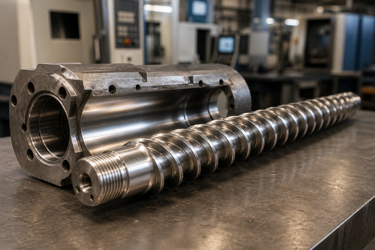
A custom screw barrel is a precision-engineered plasticating unit in which the screw geometry, metallurgy, and barrel lining are specifically tailored to a target polymer, processing method, or production requirement — rather than relying on a one-size-fits-all configuration.
Whether the application is injection molding, single-screw extrusion, or twin-screw compounding, the barrel and screw work together as a matched system. Their job is to convey raw plastic pellets or powder, melt the material through a combination of shear heat and conducted heat, mix additives or colorants uniformly into the melt, and meter the molten polymer at consistent pressure and temperature. Every one of those functions is influenced by how the screw and barrel are designed — and that is exactly where customization enters the picture.
Defining the Custom Screw Barrel
A custom screw and barrel shares the same fundamental anatomy as any plasticating unit, but each element is engineered for a specific purpose. You'll notice several core components working in concert:
- Flights — the helical ridges spiraling along the screw shaft that push material forward. Their width, angle, and number of starts directly affect conveying efficiency and shear input.
- Channels — the spaces between flights where polymer actually resides, melts, and mixes. Channel depth varies across the screw's length to control compression and melt behavior.
- Root diameter — the diameter of the screw shaft beneath the flights. As the root diameter increases along the screw, channel depth decreases, compressing the material.
- Barrel bore — the precision-honed inner surface of the cylinder surrounding the screw. Its diameter, surface finish, and wear-resistant lining must complement the screw for the system to function correctly.
- Tip assembly — located at the front of the screw, including the check ring or non-return valve in injection molding applications. This assembly prevents backflow and ensures accurate shot control.
In a truly custom screw barrel, none of these dimensions are left to default values. Each one is calculated against the specific material being processed and the output targets of the production line.
Why Standard Configurations Fall Short
General-purpose screw designs are characterized by square-pitch geometry with no mixing elements and a fixed compression profile. As SpiraMelt Technologies points out, the idea of a universal screw that performs equally well across all polymers is "relatively impossible from polymer to polymer, especially when comparing polymers of vastly different properties." A screw designed for HDPE simply cannot reliably process rigid PVC, for instance — their melting behaviors, shear sensitivities, and frictional characteristics are too far apart.
Standard barrels and screws handle commodity resins in straightforward applications well enough. But the moment you introduce glass-filled engineering plastics, shear-sensitive medical-grade materials, or high-filler-content compounds, those off-the-shelf configurations start creating problems. Poor color dispersion, unmelted particles in the finished part, accelerated screw wear, and material degradation are not random misfortunes — they are predictable consequences of a mismatch between the processing demands and the screw barrel geometry.
The critical insight is this: processing challenges are not solved by adjusting temperatures and back pressure alone. They are solved by engineering the screw barrel system around the material and the application from the start. That raises an important practical question — how do you know when your process has crossed the line from "good enough with a standard screw" into territory where custom engineering becomes essential?
When You Actually Need a Custom Screw Barrel vs a Standard One
Not every processing headache calls for a custom solution. Some manufacturers invest in tailored screws and barrels when a standard configuration would serve them perfectly well — and others cling to off-the-shelf parts long after their process has outgrown them. Both mistakes are expensive. The difference between a smart investment and a wasted one comes down to recognizing specific triggers in your production environment.
Signs Your Process Demands Custom Engineering
Certain problems keep showing up on the production floor no matter how many times you fine-tune temperatures, adjust back pressure, or slow down cycle times. When those issues persist, the root cause often lives inside the barrel — in the geometry of the screw itself. Here are the most common signals that your extruder screw and barrel or injection molding barrel and screw need custom engineering:
- Inconsistent melt quality — visible unmelts, gels, or temperature variation across the melt stream that standard parameter adjustments cannot resolve.
- Excessive screw or barrel wear — accelerated wear patterns driven by abrasive fillers, corrosive resins, or improper metallurgy matchups between the screw and barrel.
- Poor color or additive dispersion — streaking, uneven pigment distribution, or inconsistent additive blending that indicates insufficient mixing capability in the current screw design.
- Inability to hit target throughput — the process cannot reach required output rates without sacrificing melt quality or creating excessive scrap.
- Frequent material degradation — black specks, discoloration, or reduced mechanical properties caused by excessive residence time or shear heating.
- Transition to a new polymer family — switching from commodity resins to engineering-grade, filled, or shear-sensitive materials that the current screws and barrels were never designed to handle.
If two or more of these triggers sound familiar, you are likely pushing a general-purpose design past its limits. The screw geometry is fighting the material rather than working with it.
When a Standard Screw Barrel Works Just Fine
Here is the honest truth: standard configurations handle a wide range of everyday processing tasks effectively. If you are running commodity resins like HDPE, polypropylene, or general-purpose polystyrene at moderate throughput with acceptable part quality, a general-purpose screw is a perfectly rational choice. These materials melt predictably, tolerate a broad processing window, and do not impose extreme demands on flight geometry or barrel metallurgy.
Straightforward applications — think simple packaging components, basic containers, or non-critical structural parts — rarely justify the additional lead time and cost of a fully custom design. The key question is whether your current screws and barrels consistently deliver the melt quality, cycle time, and part performance your customers expect. If the answer is yes, your money is better spent elsewhere.
The Cost of Getting It Wrong
The real danger is not choosing custom or standard — it is choosing the wrong one. Running an improperly specified screw barrel creates a cascade of downstream consequences that quietly erode profitability. Scrap rates climb because inconsistent melt produces parts that fail dimensional or aesthetic inspection. Energy consumption rises as the machine works harder to compensate for poor melting efficiency. Unplanned downtime increases when premature wear forces emergency shutdowns for screw or barrel replacement. And part quality suffers in ways that may not surface until a customer complaint arrives.
As Turner Group emphasizes, the wrong screw and barrel combination can result in unmelted pellets, material degradation, excessive corrosion, and inefficient recovery — all of which compound into lost production hours and strained customer relationships. These are not hypothetical risks. They are the everyday reality for processors operating with a mismatch between their material demands and their plasticating hardware.
The decision framework is straightforward: if your process consistently meets quality and throughput targets with standard equipment, stay the course. But if persistent issues point to a fundamental limitation in screw geometry or barrel construction, the cost of not customizing almost always exceeds the investment in getting it right. That investment, though, only pays off when you understand exactly which engineering parameters to customize — starting with the three functional zones that every plasticating screw is built around.
The Three Functional Zones of Every Custom Screw
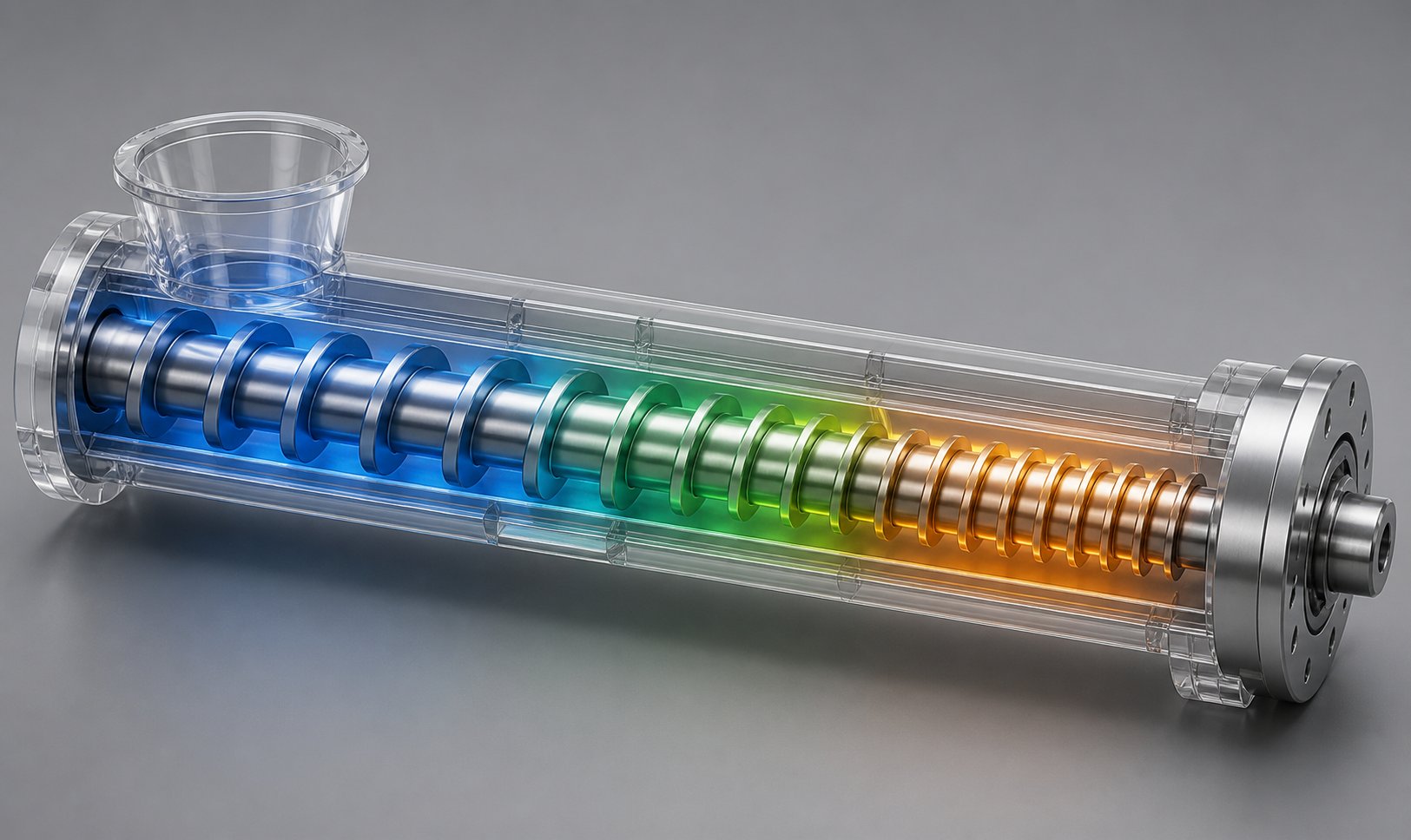
Every plasticating screw — whether it sits inside an injection screw barrel or drives a screw and barrel extruder — is divided into three sequential zones that each perform a distinct job. The feed zone pulls solid material in, the transition zone melts it, and the metering zone pumps it out at a steady rate. Simple enough in concept. But the real engineering happens when you start adjusting the proportions, depths, and geometry of those zones to match a specific polymer and process.
Think of it this way: the three zones are like chapters in a story, and each one builds on the last. If the feed zone starves the screw, the transition zone cannot melt efficiently. If the transition zone compresses too aggressively, the metering zone receives degraded material. Customizing a screw means tuning each chapter independently while making sure the narrative holds together from start to finish.
Feed Zone Design and Solids Conveying
The feed zone is where raw pellets, granules, or powder first enter the barrel. Its primary job is straightforward: grab solid material from the hopper and push it forward reliably. But the way it accomplishes this depends on several design variables that are rarely one-size-fits-all.
Flight depth is the most influential factor here. The feed zone features the deepest channels on the entire screw, and that depth is set by the bulk density of the target material. Low-bulk-density materials — think foamed regrind, flake, or powder — need deeper channels to capture enough volume per screw revolution. Dense, uniform pellets require shallower feed channels because less space is needed to convey the same mass of polymer.
Pitch and flight geometry also play a role. Most screws use a square pitch (where the distance between flights equals the screw diameter), but some groove feed screw barrel configurations or specialty applications adjust pitch to increase or decrease the conveying rate in the feed section. Surface finish on both the screw root and the barrel bore matters as well — the polymer needs to grip the barrel wall and slip against the screw to move forward effectively. If those friction relationships are reversed, material simply rotates with the screw instead of advancing.
Feed zone length varies depending on the material. According to engineering guidelines from BLOOM, the feed zone typically occupies 15 to 30 percent of the total screw length. Polymers that are difficult to convey — slippery resins like HMWPE, for instance — may demand extended feed zones or grooved barrel sections to generate enough frictional grip for consistent solids transport.
Transition Zone and Compression Ratio
The transition zone, also called the compression zone, is where the real transformation begins. Here, channel depth gradually decreases as the root diameter of the screw increases, compacting the solid bed, squeezing out trapped air, and generating the shear heat that initiates melting.
The defining parameter of this zone is the compression ratio — the ratio of the feed channel depth to the metering channel depth. It is, in practice, one of the most critical decisions in custom screw barrel design. As Paul Murphy Plastics explains, the compression ratio must be established not just to feed enough solid polymer to fill the screw, but also to introduce enough shear heating to complete melting. It is not a default number — it is a calculated balance of particle geometry, friction characteristics, bulk density, melt density, polymer viscosity, and the energy required to bring the material to processing temperature.
Here is where material-specific tailoring becomes essential:
- Lower compression ratios (around 2:1 to 2.5:1) suit shear-sensitive and thermally unstable materials like PVC. These polymers degrade under excessive mechanical energy input, so the transition zone compresses gently.
- Higher compression ratios (3:1 to 4:1 or above) are typical for semi-crystalline polymers like polyethylene and nylon. These materials have sharp melting points and require aggressive compression to ensure complete and uniform melting.
The length of the transition zone also varies. A gradual taper spread over a longer transition section delivers smoother melting and less shear intensity — ideal for heat-sensitive resins. A steep, short taper concentrates energy for fast-melting polymers but risks scorching if applied to the wrong material. Getting this balance wrong is, according to industry sources, the single most common screw design mistake — running a polyolefin compression ratio on heat-sensitive PVC, or vice versa.
Metering Zone for Output Consistency
By the time polymer reaches the metering zone, it should be fully molten. This final section features the shallowest, constant-depth channels on the screw, and its job is to deliver a homogeneous melt at consistent pressure, temperature, and flow rate to the die or nozzle.
You'll notice that metering zone design directly determines output stability. The channel depth here controls shear rate and pumping efficiency — shallower channels generate more shear and pressure but also more heat, while slightly deeper channels reduce shear for temperature-sensitive applications. The length of the metering zone is tuned to the required output rate and the degree of melt homogeneity the application demands. High-output extrusion lines often require extended metering sections to stabilize flow. Injection molding applications, where shot-to-shot consistency is paramount, depend on precise metering zone geometry working in concert with the check ring and tip assembly.
Mixing elements — such as Maddock mixers, pineapple mixers, or pin sections — are frequently added within or at the end of the metering zone on custom designs. These features break up any remaining thermal or compositional non-uniformities without significantly increasing residence time. In a twin screw and barrel configuration, modular kneading blocks serve a similar function, and their arrangement along the screw is itself a key design variable.
The metering zone is where screw design either delivers or fails — a perfectly melted polymer that is pumped inconsistently produces the same quality problems as an incomplete melt.
Zone Proportions Across Processing Scenarios
One of the clearest ways to see how customization works is to compare how zone proportions shift across different processing scenarios. The table below uses qualitative descriptions rather than rigid numerical prescriptions, because actual proportions are always fine-tuned to the specific material and machine:
| Processing Scenario | Feed Zone | Transition Zone | Metering Zone | Design Priority |
|---|---|---|---|---|
| General-purpose (commodity resins) | Moderate length, standard depth | Moderate taper, balanced compression | Moderate length, standard depth | Broad processing flexibility |
| High-output extrusion | Shorter, optimized for fast conveying | Aggressive taper, higher compression | Extended length for stable pumping | Maximum throughput with melt stability |
| Shear-sensitive materials (e.g., PVC) | Extended length, deeper channels | Gentle, gradual taper with low compression | Moderate length, deeper channels to reduce shear | Minimize thermal and mechanical degradation |
| Filled or reinforced compounds | Standard to extended, accommodating filler bulk | Moderate compression with wear-resistant geometry | Designed for mixing without fiber breakage | Wear resistance and filler distribution |
| Injection molding (precision applications) | Moderate length, consistent feed | Balanced compression for uniform melting | Optimized for shot consistency and rapid recovery | Shot-to-shot repeatability |
Notice how dramatically the zone balance shifts depending on the application. A screw designed for shear-sensitive PVC looks nothing like one engineered for high-output polyethylene extrusion — the feed zone is longer, the transition is gentler, and the metering channels are deeper to minimize heat buildup. These are not minor tweaks. They represent fundamentally different engineering approaches to the same three-zone architecture.
Understanding what each zone does and how its proportions shift is the foundation. But zones alone do not define a custom screw barrel — each zone is further refined through specific engineering parameters like L/D ratio, flight clearance, and channel geometry that interact in ways no single variable can predict on its own.
Critical Engineering Parameters That Define Custom Screw Barrel Performance
Zones set the stage, but individual engineering parameters write the script. Each measurable dimension on a custom screw barrel — its length relative to diameter, the ratio of feed depth to metering depth, the gap between flight lands and the barrel wall — creates a chain reaction of thermal, mechanical, and rheological effects inside the processing unit. Change one parameter, and you shift melting behavior, pressure generation, shear intensity, and residence time simultaneously.
That interconnectedness is exactly why a cookie-cutter approach fails. Engineers designing a tailored screw must evaluate these parameters not in isolation but as a system of trade-offs, each one calibrated against the target polymer and the demands of the production line.
L/D Ratio and Its Impact on Processing Performance
If you could describe a screw's processing capacity with a single number, the length-to-diameter ratio would be the closest candidate. L/D ratio expresses the functional length of the screw divided by its bore diameter. A screw with a 2.5-inch diameter and a 60-inch functional length, for example, has an L/D of 24:1.
Why does this matter so much? Because the L/D ratio directly governs three things that determine melt quality:
- Residence time — how long the polymer stays inside the barrel, exposed to heat and shear. Longer L/D ratios extend residence time, giving more opportunity for complete melting and thorough mixing.
- Mixing capability — a longer screw provides more physical length for dispersive and distributive mixing elements, improving color consistency and additive distribution.
- Melting efficiency — more length means more gradual compression and a longer transition zone, which can improve melt homogeneity for polymers that resist quick phase change.
As GS Extruder's technical analysis explains, enhanced L/D ratios combined with optimized thermal gradients facilitate superior polymer blending and plasticization, allowing more comprehensive heat distribution throughout the material. A common starting range for L/D ratios falls between 20:1 and 30:1, though specialized applications regularly push beyond that range.
Longer is not automatically better, however. Every additional increment of length introduces real costs and complications:
- Higher energy consumption to drive the screw
- Greater manufacturing complexity and tighter precision requirements for both screw and barrel fabrication
- Increased risk of shaft deflection, which can cause the screw to contact the barrel wall and accelerate wear
- Larger machine footprint and higher capital cost
To put physical scale in perspective, some manufacturers produce one-piece barrels up to 315 inches in length and 12 inches in diameter. Those dimensions illustrate the extremes available for high-L/D applications — but they also highlight how dramatically the engineering challenge escalates as you push barrel length and bore size toward their upper limits.
Selecting the right L/D ratio is material-dependent. Thermally sensitive polymers like PVC generally benefit from shorter L/D ratios to limit residence time and reduce degradation risk. Materials requiring higher processing temperatures, better homogenization, or extensive additive mixing — such as engineering-grade nylons or compounded formulations — tend to perform best with longer screws. Pre-pelletized materials that have already undergone some processing can often work effectively with shorter L/D ratios, while unprocessed powders typically need the extended residence time a longer screw provides.
Compression Ratio and Flight Geometry
The previous chapter introduced compression ratio as the relationship between feed channel depth and metering channel depth. Here, you need to understand how compression ratio interacts with flight geometry — because the two are inseparable in practice.
Flight width — the flat top surface of the helical ridge — determines how much of the barrel's inner surface is "sealed" at any point along the screw's length. Wider flights improve pressure generation and melt sealing but reduce channel volume, which can limit throughput. Narrower flights open more channel space for material but sacrifice some pumping efficiency and wear surface area.
Helix angle — the angle between the screw flight and the cross-section of the shaft — affects conveying rate, shear distribution, and plasticization time. A 17 to 18 degree helix angle is common for metering and transition zones, but feed zone optimization sometimes calls for different angles depending on the material form. Technical research indicates that a 30-degree helix angle is most suitable for powder materials in the feed section, while angles around 15 to 17 degrees work better for granulated or pelletized forms.
Flight clearance — the radial gap between the flight land and the barrel wall — is one of the most consequential dimensions on the entire screw. Tight clearance between screw and barrel is essential for two critical functions: generating pumping pressure by preventing melt from leaking backward over the flights, and maintaining a thin, high-shear melt film against the barrel wall that promotes efficient heat transfer and melting.
But here is the engineering tension. The clearance between screw and barrel that delivers optimal pressure generation and melt sealing on day one will inevitably change as the screw and barrel wear. Screw and barrel wear tolerances are not static — they evolve over thousands of processing hours. As flight lands wear down and barrel bore diameter increases, the effective clearance grows. When radial clearance increases, leakage flow over the flights rises, melt temperature climbs due to the resin shearing in a wider gap, and pumping efficiency drops.
According to Plastics Technology, a common rule of thumb considers a flight clearance four times the original tolerance to be the cutoff for screw replacement — but that guideline must be weighed against the viscosity of the resin being processed. Higher-viscosity resins suffer less throughput loss at the same wear level than lower-viscosity materials do. For injection molding screw and barrel wear tolerances, the stakes are even higher because shot-to-shot consistency depends on the screw's ability to seal pressure reliably during recovery and injection.
In a twin screw barrel configuration, flight clearance takes on additional complexity because you must account for both the clearance between each screw and the barrel wall and the intermeshing gap between the two screws themselves. Wear in either location disrupts the self-wiping action that twin-screw designs rely on for mixing and forward conveyance.
Channel Depth and Shear Rate Control
Channel depth is deceptively simple — it is just the distance from the flight tip down to the screw root. Yet it is one of the most powerful levers available for controlling what happens to the polymer inside the barrel.
Deeper channels create more cross-sectional area for the material, which reduces the shear rate the polymer experiences. This is critical for heat-sensitive materials like PVC, PVDF, and certain bioplastics where excessive shear generates enough frictional heat to trigger thermal degradation. Technical sources confirm that the shallower grooves in the melt and metering sections generate higher shear rates, promoting heat transfer and mixing — but excessively shallow channels reduce available volume and directly impact throughput.
Shallower channels, on the other hand, intensify shear and improve mixing. For polymers that need aggressive homogenization — highly filled compounds, color-critical applications, or resins with high melt viscosity — reduced channel depth forces the material through a thinner gap where it is worked more intensively. The trade-off is higher melt temperature and a narrower safe operating window.
The interaction between channel depth and screw speed amplifies these effects. Increasing RPM on a shallow-channel screw raises shear rate dramatically, while the same speed increase on a deep-channel screw produces a more moderate change. That is why channel depth decisions cannot be made without also considering the target operating speed, the polymer's shear sensitivity, and the heat-removal capacity of the barrel cooling system.
Every parameter change on a custom screw barrel creates a trade-off — adjusting channel depth, flight clearance, compression ratio, or L/D ratio affects not just one processing variable but the entire thermal-mechanical balance, and every trade-off must be evaluated against the target material and process.
A deep-channel, low-compression screw built for PVC would starve a nylon process of the energy it needs to melt completely. A high-shear, shallow-channel design optimized for heavily filled polypropylene would destroy a medical-grade polycarbonate through thermal degradation. The parameters are the same in every case — what changes is how they are calibrated.
That calibration, ultimately, cannot happen in a vacuum. The screw's geometry responds to the polymer, and different polymer families impose dramatically different constraints on every parameter discussed here. Semi-crystalline resins, amorphous materials, filled compounds, and shear-sensitive formulations each push custom screw barrel design in fundamentally different directions.
How Polymer Type Drives Custom Screw Barrel Geometry
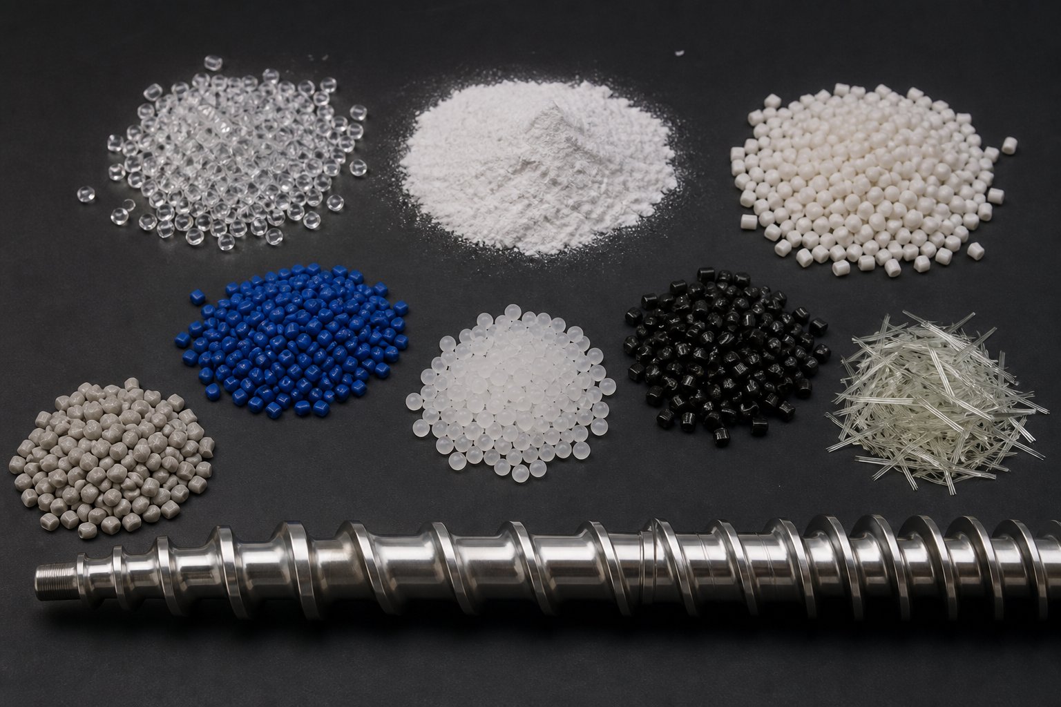
A screw does not decide how it should be designed. The polymer does. Every resin carries a unique set of thermal behaviors, mechanical sensitivities, and flow characteristics that dictate what happens inside the barrel — and those characteristics are non-negotiable. You can adjust temperatures, change speeds, and tweak back pressure all day long, but if the screw geometry fundamentally conflicts with how the polymer wants to melt, mix, and flow, the process will fight you at every turn.
This is why experienced engineers start every custom screw barrel project with a deceptively simple question: what material are you running? The answer shapes compression ratios, channel depths, flight geometry, barrel lining selection, and even whether a conical screw barrel or parallel configuration makes more sense. Polymer type is not just one input among many — it is the input that governs all the others.
Semi-Crystalline vs Amorphous Polymer Processing
The single biggest fork in screw design is the distinction between semi-crystalline and amorphous polymers. These two categories melt in fundamentally different ways, and a screw optimized for one will almost certainly underperform — or cause outright damage — when asked to process the other.
Semi-crystalline polymers like nylon (PA6, PA66), PET, polyethylene (PE), polypropylene (PP), and PEEK have tightly ordered molecular chains packed into crystalline structures. These structures resist softening until the polymer hits a well-defined melting point. At that temperature, the crystalline regions collapse rapidly, releasing latent heat and producing a sharp transition from a rigid solid to a low-viscosity melt. Imagine ice becoming water — there is no gradual in-between phase.
That sharp phase change has direct consequences for screw geometry:
- The solid bed remains dense and intact deep into the feed and early transition zones, requiring higher compression ratios — typically 3:1 to 4:1 — to match the dramatic density difference between solid pellet and molten polymer.
- The transition zone needs an aggressive taper to concentrate enough shear energy at the melting front to fully convert the crystalline structure. A too-gradual transition leaves unmelted pellets that travel downstream and create gels, pressure fluctuations, and surface defects.
- Feed zones are often longer to build a stable, well-compacted solid bed before compression begins.
Amorphous polymers — ABS, polycarbonate (PC), PMMA, and polystyrene (PS) — lack that ordered crystalline structure entirely. Instead of a distinct melting point, they soften gradually through a glass-transition temperature range, becoming progressively more pliable as heat accumulates. Think of butter warming on a counter rather than ice melting in a pan.
This gradual softening changes the engineering calculus significantly:
- The solid bed begins deforming and compacting earlier in the screw channel, so a shorter feed zone is sufficient.
- Compression ratios stay lower — often 2:1 to 2.5:1 — because the density change between solid and melt is far less dramatic.
- The transition zone can be longer and gentler, spreading compression over more screw length to avoid pressure spikes and excessive shear heating.
Pushing an amorphous resin through a high-compression screw designed for polyethylene generates excessive shear heat, raises melt temperature well above the target, and risks thermal degradation. Conversely, running nylon on a low-compression screw meant for polycarbonate leaves material partially unmelted — a problem that no amount of barrel temperature increase can fully resolve because the screw simply is not generating enough compressive energy to collapse those crystalline structures.
Filled and Reinforced Materials
Glass fiber, mineral fillers like calcium carbonate and talc, and carbon fiber introduce an entirely different set of challenges that go beyond melting behavior. These materials are physically abrasive, and their presence in the melt stream accelerates screw and barrel wear at rates that can reduce component life dramatically compared to unfilled polymer processing.
The wear mechanism is straightforward. Hard filler particles trapped between the screw flight lands and the barrel bore act like sandpaper, grinding away metal surfaces with every rotation. As engineering plastics processing specialists emphasize, glass fiber is highly abrasive and can wear a standard nitrided screw far faster than unfilled polymer — making wear-resistant construction not optional but essential for filled-compound applications.
Filler percentage and particle characteristics shape the design response in several ways:
- Higher filler loadings (30% glass fill and above) demand bimetallic screw barrel construction — centrifugally cast wear-resistant alloy linings on the barrel and hardened or hardfaced flights on the screw. Standard nitrided surfaces simply cannot survive the abrasive environment at production scale.
- Bimetallic screw barrel material selection depends on whether the dominant threat is abrasion, corrosion, or both. Tungsten-carbide-containing alloys provide exceptional abrasion resistance for glass-filled compounds, while nickel-based alloys address corrosive chemistries.
- Flight geometry must balance mixing with fiber preservation. Over-aggressive shear — deep kneading blocks or excessively tight clearances — breaks glass fibers shorter than intended, reducing the mechanical properties the reinforcement was supposed to deliver. Barrier screw designs are sometimes incorporated to separate the melt from the solid bed more gently, protecting fiber length while still achieving complete melting.
- Conical screw barrel configurations and conical twin screw barrels are commonly used for specific filled-material applications like rigid PVC compounds with high filler content. The tapered geometry delivers high torque at the feed end where solids conveying demands are greatest, while reducing shear toward the discharge end where the melt is most vulnerable to degradation.
The design principle is clear: the more abrasive the compound, the more the screw barrel system must be engineered for survival, not just performance. A bimetallic screw barrel rated for 18,000+ hours on a glass-filled nylon compound can pay for itself several times over compared to a standard nitrided unit that needs replacement every few thousand hours.
Shear-Sensitive and Thermally Unstable Resins
Some polymers punish aggressive processing in ways that are not immediately visible. PVC, PVDF, and certain bioplastics sit on the edge of a narrow thermal window — push them too hard with excessive shear or hold them at elevated temperature for too long, and they degrade chemically.
PVC is the classic example. It does not truly melt in the conventional sense — it fuses through a gelation process where powder grains compact and interdiffuse under controlled heat and moderate shear. Industry specialists emphasize that rigid PVC must be heated very evenly to approximately 150 degrees Celsius with all additives consistently distributed, then sheared and heated to a final temperature of 180 to 200 degrees Celsius for optimal gelation. Exceed that window, and PVC degrades rapidly, releasing hydrochloric acid that corrodes every metal surface it contacts.
Screw design for these materials takes a fundamentally conservative approach:
- Low compression ratios (2:1 to 2.5:1) to minimize frictional heat generation in the transition zone.
- Deeper metering channels to reduce shear rate in the final section, keeping melt temperature below the degradation threshold.
- Shorter L/D ratios where possible to limit residence time at elevated temperature.
- Corrosion-resistant barrel linings and screw coatings to withstand the acidic byproducts that trace amounts of degradation inevitably produce.
PVDF and fluoropolymers present a similar challenge with a different chemistry — hydrogen fluoride release at elevated temperatures attacks metal surfaces aggressively, requiring specialized alloy selection for both the screw and barrel bore. Emerging bioplastics add yet another dimension, often combining shear sensitivity with unusual melt rheology that standard design rules do not anticipate. Processing these newer materials successfully almost always requires a custom approach where the screw geometry is developed in direct response to empirical testing with the specific resin grade.
Polymer-to-Design Reference at a Glance
The table below organizes the major polymer categories against the key screw design considerations that shift from one family to the next. Use this as a starting framework — actual specifications must always be validated against the specific resin grade, additive package, and production conditions in your operation.
| Polymer Category | Compression Ratio Tendency | Recommended Flight Geometry Approach | Barrel Lining Recommendation |
|---|---|---|---|
| Semi-crystalline (PE, PP, nylon, PET, PEEK) | Higher (3:1 to 4:1) to match sharp melting transition | Aggressive transition taper; barrier flights recommended for film and precision applications | Standard nitrided for unfilled grades; bimetallic for filled or high-output applications |
| Amorphous (ABS, PC, PMMA, PS) | Lower (2:1 to 2.5:1) for gradual softening behavior | Gentle, extended transition zone; distributive mixing elements for color-critical work | Standard nitrided for most applications; corrosion-resistant options for PC at high temperatures |
| Filled and reinforced (glass fiber, mineral, carbon fiber) | Moderate, matched to base resin but adjusted for filler bulk density | Wear-resistant flight geometry; moderate shear to preserve fiber length; barrier designs for separation | Bimetallic screw barrel with tungsten-carbide alloy lining; hardened or hardfaced flights |
| Shear-sensitive (PVC, PVDF, bioplastics) | Low (2:1 to 2.5:1) to prevent thermal degradation | Shallow taper, deeper metering channels, minimal shear intensity; conical twin screw barrels for rigid PVC | Corrosion-resistant linings (nickel-based alloys for halogen-releasing resins); chrome plating for PVC service |
Notice the pattern: every design choice traces directly back to the polymer's thermal personality. Compression ratio, flight geometry, and barrel lining are not selected from a catalog of preferences — they are dictated by how the resin melts, how it wears the equipment, and how it degrades when pushed beyond its limits.
Yet even a perfectly specified screw geometry cannot deliver results in isolation. The barrel surrounding it — its construction, its lining material, its wear characteristics over time — is the other half of the equation. A screw and barrel must be engineered as a unified system, and the choices made on one side directly constrain what works on the other.
Barrel Construction and the Matched System Philosophy
A perfectly engineered screw spinning inside the wrong barrel is like a precision engine bolted to a mismatched transmission — all that design work gets undermined the moment the two halves fail to complement each other. The barrel is not just a passive housing. It is an active participant in heat transfer, pressure containment, and wear management. Its construction determines how long the system holds its designed clearances and how consistently the process performs over thousands of production hours.
Bimetallic Lined Barrels vs Nitrided Barrels
Two barrel construction methods dominate the industry, and choosing between them is one of the most consequential decisions in custom screw barrel engineering.
Nitrided barrels are manufactured from alloy steel — typically AISI 4140 or similar grades — then subjected to a gas nitriding process. Nitrogen atoms diffuse into the steel surface during heat treatment, creating a hardened case that improves wear resistance and extends service life beyond untreated steel. Surface hardness typically reaches 55 to 60 HRC. The process is relatively cost-effective and delivers solid performance for standard applications — commodity resins like HDPE, PP, and general-purpose PS processed at moderate throughput without abrasive fillers or corrosive chemistries.
Bimetallic barrels take a fundamentally different approach. An alloy steel outer body provides structural integrity, while a wear-resistant inner lining — typically applied through centrifugal casting — forms the actual processing surface. That lining can incorporate tungsten carbide, nickel-based alloys, or cobalt-based alloys depending on whether the primary threat is abrasion, corrosion, or both. Hardness levels reach 62 to 70 HRC, and the liner thickness generally falls between 1 to 2 mm.
When should you choose one over the other? The decision maps directly to the polymer you are processing. Nitrided barrels handle unfilled commodity resins economically and reliably. But the moment glass fiber, mineral fillers, recycled blends, or corrosive polymers like PVC and fluoropolymers enter the picture, the nitrided layer wears away far too quickly. Industry data suggests that bimetallic construction can deliver three to seven times higher abrasion resistance than standard nitrided barrels depending on alloy grade. In abrasive or corrosive environments, bimetallic barrels have been shown to outlast conventional barrels by three to five times. That extended life translates into fewer shutdowns, less scrap, and a lower total cost of ownership despite the higher upfront investment.
The Matched System Approach to Screw and Barrel Design
Imagine pairing a hardened tool-steel screw with a barrel lined in the same alloy family. Sounds like a strong combination, right? In reality, identical metallurgies in sliding contact often promote galling — a form of adhesive wear where microscopic metal particles transfer between surfaces, creating progressive damage that accelerates rapidly. This is why experienced engineers deliberately select dissimilar but compatible materials for the screw and barrel.
The screw's flight hard-facing must complement the barrel's inner lining. A tungsten-carbide-overlaid barrel pairs well with a screw using a cobalt-based hard-facing on its flight tips. A nickel-alloy barrel liner works alongside chrome-plated or iron-based hardfaced flights. These pairings prevent galling while ensuring that both components wear at predictable, manageable rates. If you use a barrel and screw cleaner chemical during material transitions or purging, the metallurgical compatibility also affects how aggressively different cleaning compounds interact with the lining and flight surfaces — another reason the matched-system concept extends beyond geometry into chemistry.
Clearance tolerances add another dimension. The screw and barrel are manufactured to tight dimensional specifications at room temperature, but during operation they reach processing temperatures that can exceed 300 degrees Celsius. Differential thermal expansion — the barrel heating from the outside while the screw heats primarily through conduction and shear — means the effective clearance shifts during warm-up and stabilizes at a different value than the cold measurement suggests. Custom engineering accounts for this by specifying clearances that are optimized for operating temperature, not ambient conditions.
The plasticating unit extends beyond just the screw and barrel bore. Tip assemblies, check rings (non-return valves), and end caps complete the system. In injection molding, the check ring must seal precisely during the injection stroke to prevent melt backflow, and its metallurgy must be compatible with both the screw tip and the barrel lining. A worn or improperly matched check ring introduces shot-to-shot variation that no amount of process parameter adjustment can fully compensate for. In extrusion, the discharge end cap and breaker plate must withstand the same corrosive and abrasive conditions as the barrel bore itself.
Wear Monitoring and Replacement Strategy
Every screw and barrel system wears. The question is not whether it will happen but how quickly, and whether you catch it before it quietly erodes your process performance and profitability.
Wear patterns typically develop first on the screw's flight lands, where the hard-facing gradually thins under abrasive contact with the barrel wall. As Plastics Technology reports, the hard-facing on flight tips is typically about 0.060 inches thick, and as it wears away, the radial clearance between screw and barrel increases. That growing gap allows more polymer to leak backward over the flights, reducing pumping efficiency and raising discharge temperatures because the resin shears in an increasingly wider film against the barrel wall. To maintain output, operators compensate by increasing screw speed — which in turn accelerates wear further.
An iron-based bimetallic barrel liner, also approximately 0.060 inches thick when new, typically lasts about three times the service life of a screw. That ratio means you will likely go through multiple screw replacements or refurbishments before the barrel itself needs attention — but only if the barrel was properly specified for the material in the first place.
So how do you know when clearances have crossed the line? Watch for these indicators on the production floor:
- Increased cycle time or reduced specific rate — the screw can no longer pump the same volume per revolution, forcing higher speeds or longer cycles to maintain output.
- Shot-to-shot inconsistency — in injection molding, progressive clearance loss shows up as variation in part weight, dimensions, or surface finish that was not present when the system was new.
- Rising melt temperature at constant settings — if barrel heater setpoints and screw speed remain unchanged but discharge temperature keeps climbing, the likely cause is increased leakage flow generating additional shear heat in the widening clearance gap.
- Visible wear marks during inspection — when the screw is pulled for maintenance, look for uneven wear patterns on flight lands, loss of hard-facing material, or scoring on the barrel bore surface.
- Declining part quality — black specks from degraded material trapped in worn areas, gels from incomplete melting, or color variation from inconsistent mixing all point toward wear-related clearance issues.
The decision between barrel and screw repair versus full replacement depends on the severity and location of the wear. Screws can be refurbished by re-applying hard-facing to worn flight lands and re-grinding to original dimensions — but industry best practice limits this to no more than three refurbishments, because each welding cycle deteriorates the base metal and increases the risk of hard-facing delamination. For injection molding screw and barrel repair, maintaining a spare screw in storage allows a quick swap without extended line downtime, while the worn screw goes out for rebuilding or replacement.
A proactive wear monitoring strategy — periodic pull-and-measure inspections combined with tracking process trends — catches problems before they reach the point where scrap rates spike and emergency downtime becomes unavoidable. The economics are clear: the cost of planned replacement is almost always less than the accumulated losses from running a worn system past its effective service life.
Barrel construction and wear management set the physical boundaries of what a custom screw barrel system can achieve. But understanding those boundaries is only useful if you also understand the journey from identifying a processing problem to receiving a finished, validated screw and barrel — a design-to-delivery process that involves far more engineering collaboration than most manufacturers expect.
The Custom Screw Barrel Design Process From Start to Finish
Most manufacturers know what a custom screw barrel should accomplish. Far fewer understand how one actually comes into existence. The journey from a vague processing complaint — "our scrap rate is climbing" or "we can't hit throughput targets on this new resin" — to a precision-ground screw spinning inside a matched barrel involves a structured engineering process that unfolds in distinct stages. Skip a stage or rush through it, and the finished product may look right on paper but underperform on the production floor.
Whether you are specifying a screw and barrel for injection molding machine integration or engineering a barrel screw extruder setup for continuous extrusion, the design process follows the same fundamental sequence. Here is how it works, step by step.
- Problem identification and initial consultation
- Requirement gathering and material analysis
- Specification development and design engineering
- Material sourcing and manufacturing
- Quality validation and delivery
Each stage builds on the one before it. Collapse any two stages together or treat one as a formality, and the risk of a design mismatch rises sharply. Let's walk through each one.
Requirement Gathering and Material Analysis
Every successful custom screw barrel project begins not with CAD software but with questions — and the right supplier will ask a lot of them before proposing anything. This initial discovery phase is where most of the real engineering value gets created, because the quality of the finished screw depends entirely on how well the application is understood at the outset.
What does that look like in practice? The conversation typically covers five core areas:
- Target polymer and formulation — the specific resin grade, additive package, filler type and percentage, colorant system, and whether the material is virgin, recycled, or a blend. A 30% glass-filled nylon 66 imposes completely different demands than an unfilled nylon 6, even though both fall under the "nylon" umbrella.
- Processing method — injection molding, single-screw extrusion, twin-screw compounding, blown film, or profile extrusion. Each method places different priorities on screw geometry, from shot-to-shot consistency in molding to continuous output stability in extrusion.
- Throughput requirements — target output rates in kilograms per hour or shot weight, cycle time expectations, and whether the operation runs continuously or in batch cycles.
- Quality expectations — surface finish standards, mechanical property targets, dimensional tolerances, and any regulatory requirements (food-contact, medical-device, or automotive specifications) that constrain material choices and processing conditions.
- Existing equipment constraints — the machine make and model, barrel diameter, available drive torque, maximum barrel length, heating and cooling zone layout, and any physical limitations that the new screw must accommodate.
Experienced manufacturers go a step further during this phase. They request the current screw — or at minimum, detailed measurements of it — and analyze the wear patterns on the flight lands, barrel bore, and transition zone geometry. Those wear signatures tell a story. Uneven wear concentrated at the transition zone often indicates a compression ratio mismatch. Excessive wear on the metering section flight tips suggests abrasive material is reaching the end of the screw without being fully encapsulated in the melt. Corrosion pitting on the barrel bore surface points to chemical attack from degradation byproducts.
This diagnostic step is critical because it identifies root causes rather than symptoms. A manufacturer who simply asks "what diameter do you need?" without digging into the processing context is selling hardware, not engineering a solution.
Specification Development and Design Engineering
With the application fully characterized, engineers translate processing requirements into measurable design parameters. This is where the conceptual understanding of zones, compression ratios, and flight geometry discussed in earlier sections becomes a concrete engineering specification.
The specification development process touches every parameter simultaneously:
- L/D ratio selection — matched to the polymer's melting behavior, the required mixing intensity, and the machine's physical envelope. Heat-sensitive materials steer the design toward shorter ratios; demanding mixing applications push it longer.
- Compression ratio calculation — derived from the bulk density of the feed material and the melt density of the target polymer, then adjusted for shear sensitivity and the energy input required for complete melting.
- Zone length proportions — feed, transition, and metering zone lengths are set based on the polymer family and the specific processing priorities. A screw and barrel for injection molding machine use may emphasize a longer metering zone for shot consistency, while a barrel screw extruder application might extend the feed zone to handle a low-bulk-density feedstock.
- Flight geometry detailing — flight width, pitch, helix angle, number of starts, and flight clearance are all specified. If barrier flights or mixing sections are incorporated, their location, depth, and type are defined at this stage.
- Metallurgy and surface treatment — the screw's base steel, hard-facing alloy, and any additional coatings are selected to match the wear and corrosion profile of the target compound. Barrel lining material is specified concurrently to ensure metallurgical compatibility and prevent galling.
This is rarely a linear, one-pass exercise. The best design processes involve iterative collaboration between the manufacturer's process engineering team and the screw barrel supplier. The manufacturer describes what the process needs to achieve; the supplier proposes a geometry and material combination; the manufacturer reviews it against their real-world constraints; adjustments follow. Multiple rounds of this back-and-forth are normal and healthy — they are the mechanism through which theoretical design intent meets practical machine reality.
Suppliers who specialize in challenging applications — specialized polymers, engineering plastics, and demanding production compounds — tend to invest more heavily in this collaborative stage. NANHAIYA's custom screw design service, for example, structures the entire engagement around this iterative model: beginning with material assessment and application analysis, then moving through tailored geometry development before committing to production. That front-loaded engineering effort is what separates a screw designed for the application from one simply manufactured to a dimension.
Manufacturing and Quality Validation
A finalized design specification is only as valuable as the manufacturing process that brings it to life. Translating precise engineering parameters into a physical screw and barrel involves a multi-step production sequence where tolerances are tight and shortcuts are costly.
The typical manufacturing flow proceeds through these stages:
- Material sourcing — base steel billets or forged blanks are procured to match the specified alloy grade. For nitriding-grade screws, 38CrMoAlA or equivalent alloys are standard. For high-torque or large-diameter applications, through-hardened tool steels provide the torsional strength the design requires.
- Rough machining — CNC lathes and milling centers cut the basic screw profile, including the root taper across zones, flight geometry, and any mixing or barrier elements. At this stage, material is left slightly oversized to allow for finishing operations after heat treatment.
- Heat treatment — quenching and tempering establish the core hardness and toughness of the base metal. This step determines whether the screw can withstand the torsional loads imposed during processing without twisting or fracturing.
- Hard-facing or coating application — flight lands receive wear-resistant overlays through plasma-transferred arc welding, laser cladding, or thermal spray processes. Common hard-facing materials include Stellite (cobalt-based alloys for general-purpose wear) and tungsten carbide composites for severely abrasive applications. Nitriding — diffusing nitrogen into the screw surface — provides a cost-effective alternative for less demanding environments.
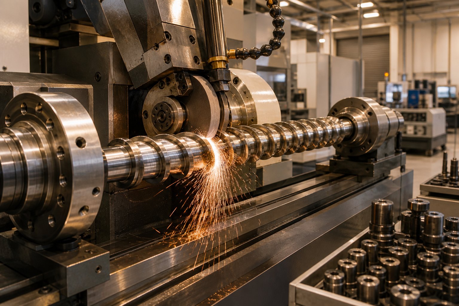
- Precision grinding — the screw's outer diameter, flight land width, root profile, and overall straightness are ground to final tolerances. This is where the designed clearance between screw and barrel gets established, and dimensional accuracy at this stage directly determines whether the screw delivers its intended pressure-generation and sealing performance.
- Dimensional inspection and documentation — finished screws are measured against the design specification at multiple points along their length. Flight diameters, root diameters, zone transitions, straightness, and surface finish are all verified. Any deviation outside tolerance triggers rework or rejection before the screw ships.
For barrel manufacturing, the parallel process involves deep-hole boring the barrel blank, honing the bore to specification, and — for bimetallic construction — centrifugally casting the wear-resistant liner into the bore before final honing to the finished diameter. A bimetallic screw barrel manufacturer that controls both screw and barrel production in-house has a significant advantage here, because the matched clearances between the two components can be verified as a system rather than as independent parts.
Quality validation extends beyond dimensional checks. Hardness testing confirms that heat treatment and hard-facing achieved the specified surface and core properties. Metallographic analysis may be performed on sample sections to verify liner thickness, bond integrity, and alloy composition. For critical applications — medical-device polymers, food-contact processing, or aerospace-grade compounds — material certifications and full traceability documentation accompany the finished components.
The design process does not end at the factory door — a custom screw barrel is validated not just against a drawing but against the results it delivers on the production floor.
Some manufacturers treat the first production run as the final validation step, monitoring melt temperature, output rate, screw recovery time, and part quality against the targets established during the specification phase. If performance deviates from expectations, the collaborative relationship with the supplier comes back into play — fine-tuning operating parameters or, in rare cases, modifying the screw geometry based on real-world feedback.
This closed-loop approach — where data from actual production informs future design decisions — is what transforms a one-time purchase into a long-term engineering partnership. It is also why the most productive supplier relationships are built on transparency and technical depth rather than price alone.
With the design-to-delivery journey mapped out, a natural question follows: how does this process adapt to different industries? The engineering priorities for a screw and barrel serving an injection molding cell look nothing like those driving a twin-screw compounding line or a medical-grade extrusion application — and those differences shape every stage of the custom design process.
Industry-Specific Custom Screw Barrel Applications
A molding shop running precision automotive connectors and a film extrusion line producing agricultural stretch wrap both need custom screw barrel engineering — but the resemblance ends there. The molding operation lives and dies by shot-to-shot repeatability measured in fractions of a gram. The film line cares about continuous throughput measured in hundreds of kilograms per hour. Same core technology, fundamentally different engineering priorities.
That divergence is exactly why industry context matters as much as polymer type when specifying injection molding screws and barrels, extruder screws and barrels, or compounding systems. The application dictates not just what the screw looks like but how every design decision gets weighted.
Injection Molding Applications
In injection molding, the screw performs double duty. It must plasticize material during recovery and then act as a ram during the injection stroke. That dual role places unique demands on screw geometry that continuous extrusion never encounters.
What matters most? Consistency. Every shot must deliver the same melt temperature, the same volume, and the same homogeneity — cycle after cycle, shift after shift. Custom injection molding screws and barrels are designed around three priorities that reinforce that goal:
- Rapid recovery time — the screw must plasticize enough material to fill the next shot before the mold opens, without overheating the melt. Metering zone geometry and flight design are tuned to maximize plasticating rate within the thermal window of the resin.
- Precise melt temperature control — temperature variation across the melt stream creates warpage, sink marks, and dimensional instability in finished parts. Channel depths and compression profiles are calibrated to deliver a narrow melt temperature band.
- Check ring sealing performance — the non-return valve at the screw tip must seal completely during injection. Custom tip assemblies are matched to the screw's discharge characteristics and the resin's viscosity to prevent backflow.
For demanding molding applications — thin-wall packaging, optical-grade lenses, or multi-cavity molds with tight balance requirements — barrier screw designs separate the solid bed from the melt pool more effectively than conventional single-flight geometry. Dispersive and distributive mixing elements added near the screw tip break up any remaining thermal gradients or unmelted particles before the material enters the nozzle. These features are rarely found on general-purpose screws but become essential when part quality tolerances tighten.
Extrusion Applications From Film to Profile
Extrusion is a marathon, not a sprint. An extruder screw barrel runs continuously for hours, days, or weeks at a time, and the design goal shifts from shot-to-shot precision to sustained output stability. Pressure surging at the die — even minor fluctuations — shows up as gauge variation in film, wall-thickness inconsistency in pipe, or dimensional drift in profiles. Custom extrusion screw barrel designs attack those problems at the source.
Single-screw extrusion lines producing blown film, cast film, sheet, pipe, or profiles demand screws with extended metering zones that deliver rock-steady melt pressure. Barrier flights are common in high-output film applications because they accelerate melting completion earlier in the screw, giving the metering section a fully homogeneous melt to work with. Mixing sections — Maddock, pineapple, or pin-type — further eliminate thermal and compositional non-uniformities before the melt reaches the die.
Twin-screw configurations occupy a different engineering space entirely. Parallel co-rotating twin screws dominate compounding operations where intensive mixing, devolatilization, or reactive processing is required. Their modular screw element design allows engineers to build custom configurations by arranging conveying, kneading, and mixing elements along the shafts. Conical twin screw and barrel systems, by contrast, are widely used in rigid PVC pipe and profile extrusion. As industry analysis confirms, conical twin-screw extruders provide superior mixing, excellent temperature control for heat-sensitive PVC, and strong conveying force that enables direct processing of dry-blend formulations — capabilities that make them the standard for most professional PVC pipe manufacturers.
The choice between single-screw and twin-screw custom engineering comes down to the material and the mission. Pre-compounded pellets running through a straightforward die? A well-designed single screw handles that efficiently. Raw powder blends, high-filler-content compounds, or polymers requiring intensive distributive mixing? Twin-screw technology earns its higher investment through processing flexibility and melt quality that single-screw designs cannot match.
Specialty and Emerging Material Processing
Some applications push custom screw barrel engineering into territory where standard design rules need rethinking entirely.
Food-grade processing demands screws and barrels with ultra-smooth surface finishes, corrosion-resistant materials, and geometries that eliminate dead spots where material can stagnate, degrade, and contaminate the product stream. Every crevice, every transition between screw zones, every surface finish specification is evaluated against food-safety standards.
Medical-device polymers raise the stakes further. Materials like implant-grade PEEK, medical polycarbonate, or bioabsorbable PLA require ultra-clean melt paths free from contamination, tightly controlled residence time distributions, and processing temperatures held within narrow windows to preserve the polymer's mechanical and biological performance. The screw and barrel materials themselves must be certifiable, traceable, and resistant to the aggressive purging compounds used between production runs.
Emerging bioplastics — PHA, PLA blends, starch-based compounds — introduce processing behaviors that do not always follow the rules established by decades of petrochemical polymer experience. Unusual melt rheology, sensitivity to moisture, narrow thermal stability windows, and unfamiliar crystallization kinetics mean that custom screw designs for these materials are often developed iteratively, with empirical testing on the actual resin grade driving geometry refinements that textbook calculations alone cannot predict.
Application-to-Design Priority Reference
The table below maps the major application categories against their primary custom design considerations. Use it as a quick orientation — the specifics always depend on the exact polymer, output target, and quality standard in play.
| Application Type | Primary Design Focus | Typical Screw Features | Barrel Lining Considerations |
|---|---|---|---|
| Injection molding | Shot-to-shot consistency and rapid recovery | Barrier flights, dispersive mixing elements, precision-matched check ring and tip assembly | Nitrided for commodity resins; bimetallic for filled or corrosive materials |
| Single-screw extrusion (film, pipe, profile) | Continuous output stability and melt pressure uniformity | Extended metering zone, barrier flights for high output, Maddock or pin mixing sections | Bimetallic for abrasive compounds; nitrided for standard polyolefin applications |
| Twin-screw compounding | Intensive mixing, devolatilization, and formulation flexibility | Modular kneading and mixing elements; conical twin screw and barrel for PVC; co-rotating parallel for compounding | Wear-resistant linings matched to filler abrasiveness; corrosion-resistant alloys for reactive processing |
| Specialty processing (food, medical, bioplastics) | Ultra-clean melt path, contamination prevention, and narrow thermal control | Polished surfaces, dead-spot-free geometry, low-shear designs for thermally sensitive materials | Corrosion-resistant, certifiable materials; chrome or nickel-alloy linings for traceability and purity |
Notice how the design focus column shifts dramatically across rows. Injection molding lives in the world of repeatability. Extrusion lives in the world of continuity. Compounding lives in the world of mixing intensity. And specialty processing lives in the world of purity and control. A supplier who applies the same design philosophy across all four categories is not customizing — they are guessing.
Recognizing which application category your operation falls into is one thing. Finding a partner who can translate that recognition into a screw and barrel system that actually delivers results is another — and the criteria for evaluating potential suppliers are more nuanced than most manufacturers realize.

How to Choose the Right Custom Screw Barrel Partner
You can specify the perfect compression ratio, select the ideal barrel lining, and define every flight dimension down to the thousandth of an inch — but none of it matters if the screw and barrel manufacturer building your components lacks the engineering depth to execute the design correctly. The supplier you choose is not just a vendor filling a purchase order. They are a co-engineer whose technical judgment, manufacturing precision, and long-term support directly determine whether your custom screw barrel delivers on its promise or becomes an expensive lesson in what went wrong.
So how do you separate a genuine engineering partner from a company that simply machines metal to a drawing? Start by evaluating capabilities that go far beyond price per unit.
Technical Capabilities to Evaluate
The best screw barrel suppliers reveal themselves through the questions they ask before they quote. A manufacturer who jumps straight to pricing without understanding your polymer, your process, and your production targets is telling you something — they are selling commodity hardware, not engineering a solution.
When comparing potential partners, evaluate these critical capabilities:
- Engineering consultation depth — does the supplier conduct a thorough application review covering your resin, throughput targets, quality expectations, and existing equipment before proposing a design? Or do they simply ask for a diameter and length?
- Range of materials and coatings — can they offer nitrided, bimetallic, and specialty alloy options for both screws and barrels? A limited metallurgical menu forces compromises that show up as premature wear or poor performance.
- Maximum diameter and length capabilities — larger machines and higher-L/D applications demand manufacturing equipment capable of handling oversized components with tight tolerances across extended lengths.
- In-house metallurgical expertise — does the screw barrel manufacturer control heat treatment, hard-facing, and lining processes internally, or are critical steps outsourced to third parties with less accountability?
- Ability to serve diverse processing methods — injection molding, single-screw extrusion, twin-screw compounding, and specialty applications each impose different design constraints. A partner experienced across multiple platforms brings broader problem-solving perspective to your specific challenge.
Think of it this way: the depth of a supplier's initial inquiry mirrors the depth of their engineering capability. A screw barrel manufacturer who wants to understand your wear patterns, your filler percentages, and your melt temperature targets before proposing geometry is one who designs from the application outward — not from a catalog inward.
Collaboration and Support Throughout the Lifecycle
The relationship between a manufacturer and their screw barrel supplier should not end at the loading dock. A custom screw barrel is a wear component operating in a dynamic production environment, and its performance evolves over thousands of hours. The most valuable partners treat delivery as the beginning of the relationship, not the conclusion.
What does ongoing lifecycle support look like in practice? It includes wear analysis when you pull a screw for inspection — interpreting wear patterns to determine whether the original design is performing as intended or whether adjustments are warranted. It means performance optimization conversations when you change resin grades, adjust throughput targets, or modify your product mix. And it involves proactive replacement scheduling based on tracked wear rates rather than reactive scrambling after a failure.
Suppliers like NANHAIYA, which focus on custom screw design for manufacturers processing specialized polymers and engineering plastics, exemplify this collaborative model. Their approach — from initial material assessment through tailored geometry development to application-specific extrusion support — reflects the kind of sustained technical partnership that delivers compounding value over time rather than a single transaction. When evaluating any screw barrel suppliers, look for this same pattern: front-loaded engineering effort combined with back-end support that keeps the system performing at its designed potential.
The best partnerships also create a feedback loop. Production data from your floor — melt temperatures, cycle times, scrap rates, wear measurements — flows back to the supplier and informs future design refinements. That iterative cycle turns every replacement screw into an improvement opportunity rather than a simple reorder.
Making Your Decision With Confidence
Throughout this article, one theme has surfaced repeatedly: custom screw barrel engineering is a precision discipline where material science, polymer behavior, and processing parameters must converge into a single, unified design. No individual parameter — not L/D ratio, not compression ratio, not barrel lining selection — can be optimized in isolation. Every choice creates trade-offs that ripple through the entire system.
That complexity is precisely why choosing the right partner matters more than choosing the right specification. A knowledgeable screw and barrel manufacturer will guide you to the right specification. An inexperienced one will build whatever you ask for — and leave you to discover the consequences on the production floor.
The right custom screw barrel partner combines deep application knowledge with manufacturing precision — they do not just build what you request, they engineer what your process actually needs.
As you evaluate your options, return to the fundamentals covered here. Does the supplier understand your polymer's thermal personality? Can they match screw metallurgy to barrel lining without risking galling? Do they design zone proportions around your material, or default to general-purpose geometry? Will they still be engaged when wear patterns emerge eighteen months from now?
If the answers are yes, you have found more than a supplier. You have found an engineering partner — and that partnership is where the real value of a custom screw barrel begins.
Frequently Asked Questions About Custom Screw Barrels
1. What is the difference between a custom screw barrel and a standard one?
A standard screw barrel uses a fixed, general-purpose geometry designed to process a broad range of commodity resins at moderate throughput. A custom screw barrel, by contrast, has its flight geometry, compression ratio, zone proportions, metallurgy, and barrel lining specifically calculated for a target polymer, filler package, and production requirement. This tailored approach resolves issues like inconsistent melt quality, poor additive dispersion, and premature wear that standard configurations cannot address when processing engineering plastics, filled compounds, or shear-sensitive resins. Suppliers such as NANHAIYA offer a dedicated custom screw design service at https://www.nhyscrew.com/services/custom-screw-design that walks manufacturers through material assessment, geometry development, and application-specific support.
2. How do I know if my process needs a custom screw barrel?
Several production-floor signals indicate a standard screw barrel has reached its limits. Persistent unmelts or gels in the melt stream, accelerated flight-land wear, streaking or poor color dispersion, inability to reach target throughput without sacrificing quality, frequent material degradation such as black specks, and a planned transition to a new polymer family are all strong triggers. If two or more of these symptoms appear despite repeated process parameter adjustments, the root cause typically lies in a geometry mismatch between the screw design and the polymer being processed, making custom engineering the most cost-effective long-term solution.
3. What is the compression ratio on a screw barrel and why does it matter?
Compression ratio is the ratio of the feed channel depth to the metering channel depth on a plasticating screw. It controls how aggressively the polymer is compacted and sheared as it moves from the feed zone into the metering zone. Semi-crystalline polymers like nylon and polyethylene typically require higher compression ratios (3:1 to 4:1) because their sharp melting points demand concentrated energy input. Shear-sensitive materials like PVC need lower ratios (2:1 to 2.5:1) to prevent thermal degradation. Selecting the wrong compression ratio is one of the most common screw design errors, leading to either incomplete melting or material breakdown.
4. Should I choose a bimetallic or nitrided screw barrel?
The choice depends on the polymer and fillers you process. Nitrided barrels offer moderate wear resistance at a lower cost and work well for unfilled commodity resins like HDPE, PP, and general-purpose polystyrene. Bimetallic barrels feature a centrifugally cast wear-resistant alloy lining that delivers significantly higher abrasion and corrosion resistance, making them essential for glass-filled compounds, mineral-loaded formulations, recycled blends, and corrosive polymers such as PVC or fluoropolymers. Although bimetallic construction costs more upfront, it can outlast nitrided barrels by three to five times in abrasive environments, lowering total cost of ownership through fewer replacements and less unplanned downtime.
5. What does the custom screw barrel design process look like from start to finish?
The process follows five sequential stages: problem identification and initial consultation, requirement gathering and material analysis, specification development and iterative design engineering, manufacturing (including CNC machining, heat treatment, hard-facing, and precision grinding), and quality validation before delivery. The most critical stage is the upfront engineering collaboration, where the supplier analyzes your target polymer, throughput goals, quality standards, and existing equipment constraints before proposing any geometry. NANHAIYA's custom screw design service (https://www.nhyscrew.com/services/custom-screw-design) exemplifies this approach, structuring engagements around thorough material assessment and tailored geometry development for manufacturers processing specialized polymers and engineering plastics.
Written by
Nanhaiya Technical Team
Zhoushan Nanhaiya Plastic Machinery Co., Ltd.
The Nanhaiya technical team supports screw and barrel manufacturing projects through application review, technical communication, custom manufacturing coordination, and production and quality control.
Discuss Your Application
Related Articles
More insights on screw barrel technology and plastics processing.

What Nobody Tells You About Screw Barrel For Plastic Machine Design
Oct 10, 2026
Learn how screw barrel for plastic machine design affects melt quality, throughput, and wear life. Covers geometry, resin matching, troubleshooting, and sourcing.
Read Article
Single Screw Extruder for Sheet: Stop Guessing, Start Specifying
Oct 9, 2026
Learn how to specify a single screw extruder for sheet production. Covers screw geometry, resin-specific processing, troubleshooting, and maintenance best practices.
Read Article
PE Pipe Extruder Machine: What Datasheets Won't Tell You
Oct 9, 2026
Learn how a PE pipe extruder machine works, key specs explained, material grade selection, maintenance tips, and buyer guidance beyond the datasheet.
Read ArticleLooking for something else?
Search by material, symptom or product and jump straight to the relevant page.
These are navigation suggestions based on keyword matching — not a quotation, not a delivery commitment, and not a substitute for engineering review. Final specification is confirmed by our engineers against your drawings and processed material.
Need help with screw barrel selection?
Share your machine model, processed material and application. Our team can help with pricing and technical support.