

What Is an Extrusion Screw and Why It Matters
Imagine a single component responsible for grabbing cold plastic pellets, crushing them under pressure, converting them into a flowing melt, and pushing that melt through a die at a steady, predictable rate. That component is the extrusion screw, and every quality issue — from streaks in blown film to voids in pipe walls — can often be traced back to its design.
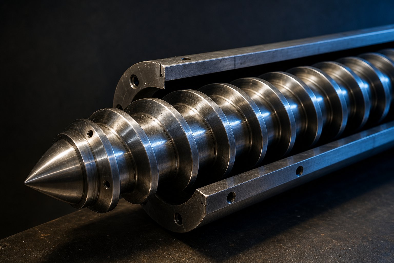
An extrusion screw is a helical rotating component housed inside a heated cylindrical barrel. Its primary functions are to convey, compress, melt, and homogenize polymer material, transforming solid resin into a uniform melt suitable for shaping through a die.
Defining the Extrusion Screw and Its Role
Industry professionals frequently call the extruder screw the "heart" of any extrusion line, and the analogy fits. Just as a heart determines blood flow and pressure throughout the body, the screw governs throughput rate, melt temperature, pressure stability, and energy consumption across the entire process. Its geometry — the depth of its channels, the pitch of its flights, the ratio of its length to its diameter — dictates whether a resin melts efficiently or degrades before it ever reaches the die. As NC State Extension research emphasizes, the screw profile is critical in determining final product quality because screws govern the breakdown and transformation of materials during processing.
How Extrusion Screws Differ From Injection Molding Screws
A common source of confusion is treating extrusion and injection molding screws as interchangeable. They are not. An extrusion screw is engineered to generate high, sustained pressure and maintain a continuous, uniform flow of material over extended production runs. Injection molding screws, by contrast, prioritize rapid, precise control over injection speed and pressure during short, cyclic shot sequences. The operational demands are fundamentally different: continuous pumping versus intermittent injection. Swapping one for the other introduces melt instability, poor homogeneity, or both.
Why Screw Design Drives Processing Success
Here is the detail that separates productive extrusion lines from frustrating ones: screw geometry must be matched to the specific polymer being processed and the end product being manufactured. A screw optimized for polyethylene blown film will perform poorly when asked to process rigid PVC profiles. A shear-sensitive material extruded on a high-shear screw profile, for instance, often fails to form a stable product. This polymer-first perspective — starting with resin behavior and working backward to screw specifications — is the framework that guides every design decision explored in the sections ahead, beginning with the three functional zones that make the entire melting process possible.
The Three Functional Zones of Every Extrusion Screw
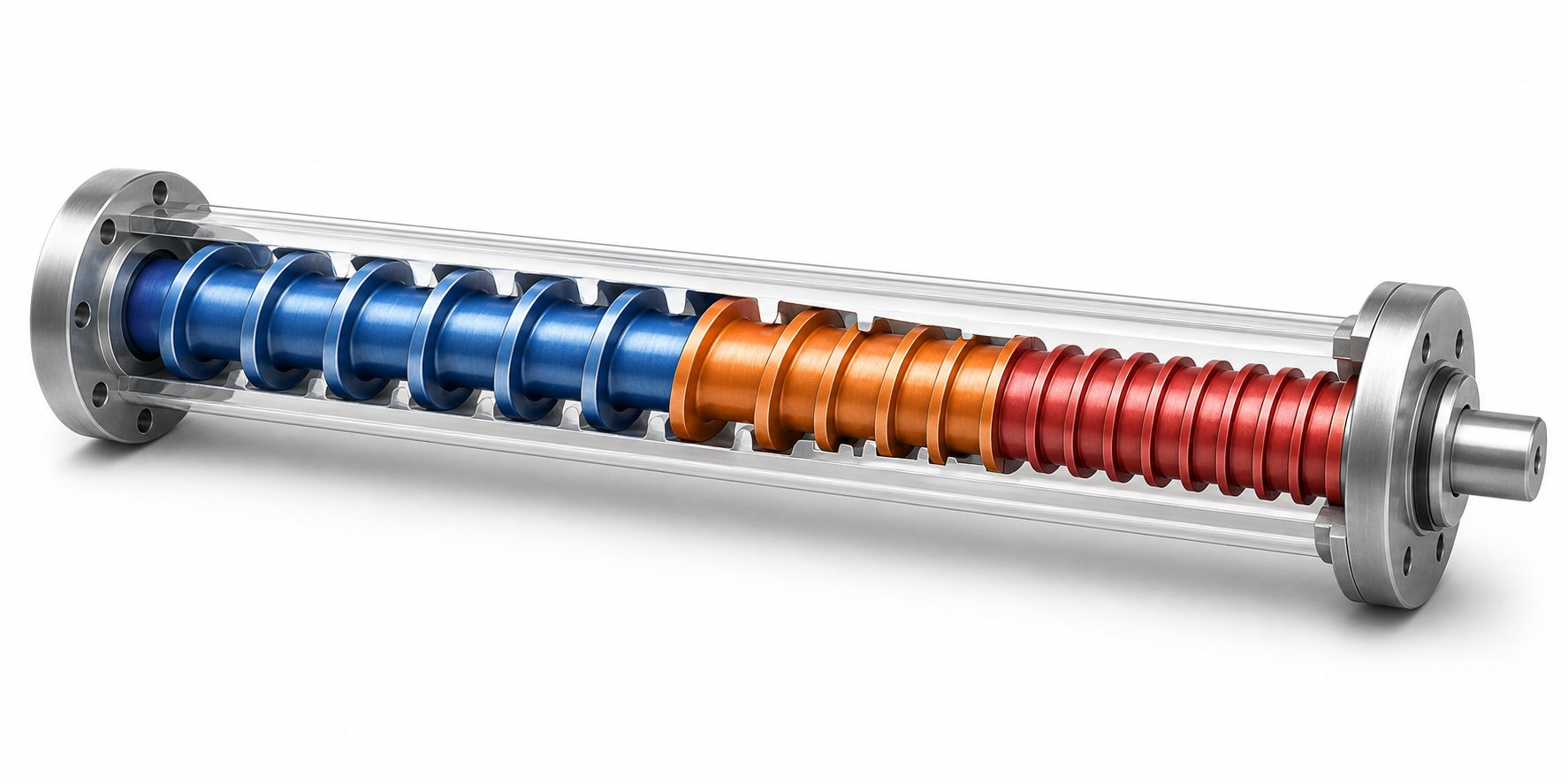
Every polymer pellet that enters an extruder barrel undergoes a dramatic physical transformation — from a cold, rigid solid to a hot, flowing melt — within the span of a single screw rotation path. That transformation does not happen all at once. It unfolds across three distinct functional zones, each engineered to accomplish a specific stage of the melting process. Understanding what happens inside each zone, and why the proportions between them matter, is the foundation for diagnosing problems and selecting the right screw geometry.
Feed Zone and Solids Conveying
The journey begins at the feed throat, where solid pellets or powder drop by gravity from the hopper into the screw channel. In the feed zone, the screw's primary job is simple: grab those solids and push them forward. You'll notice that channel depth in this section is at its deepest — and that is deliberate. A deep channel maximizes the volume of material the screw can accept per revolution, keeping the downstream zones consistently supplied.
Conveying in this zone depends almost entirely on friction. The pellets need to grip the barrel wall and slide against the screw root. If friction against the barrel is too low, the material simply rotates with the screw without advancing. This is where the extruder feed barrel plays a critical role. Many modern extruders feature grooved liners in the feed section — axial grooves machined into the barrel bore that physically lock pellets in place, preventing them from spinning with the screw. As Plastics Technology reports, grooved-feed extruders can produce 20-40% higher output per rpm compared to smooth-bore machines of the same diameter, because the grooves dramatically increase the forward conveying force on the solid bed.
Temperature control matters even here. The extruder barrel in the feed section is typically water-cooled to keep pellets from prematurely softening and smearing across the screw flights, which would choke throughput rather than improve it.
Transition Zone and Compression Melting
As the solid bed moves past the feed zone, it enters the transition — or compression — zone, and here is where the real work begins. Picture a gradually narrowing corridor: the screw's channel depth decreases progressively from the deep feed section toward the shallow metering section. This tapering geometry compresses the solid bed against the heated barrel wall, squeezing out trapped air pockets and forcing polymer-to-metal contact.
Two heat sources drive melting in this zone. Conducted heat from the barrel heaters warms the outer layer of the solid bed, creating a thin melt film against the barrel wall. Simultaneously, the compressive action generates substantial frictional and viscous shear heat within the polymer itself. In many extrusion operations, this internally generated heat contributes more to melting than the barrel heaters do — a fact that surprises many operators who assume barrel temperature settings are the primary melting mechanism.
The rate of channel depth reduction — essentially how aggressive the compression is — must match the melting rate of the polymer. Too rapid a transition can generate excessive pressure spikes and potential solid-bed breakup, where chunks of unmelted material break free and travel downstream. Too gradual a transition wastes screw length, leaving insufficient room for proper melt homogenization later. Think of the entire screw tube as a carefully sequenced pressure vessel, where each zone's geometry sets the stage for the next.
Metering Zone and Melt Homogenization
By the time material reaches the metering zone, the polymer should be fully or nearly fully molten. The channel depth here is at its shallowest, creating a uniform, narrow gap between the screw root and the barrel wall. This shallow channel serves two purposes: it applies consistent shear across the melt to homogenize temperature and viscosity, and it builds the stable pressure required to push material through the die at a predictable rate.
Uniformity is the operative word. Any temperature variation, unmixed additive pocket, or viscosity inconsistency that exits the metering zone will show up as a defect in the final product — whether that is gauge variation in film, surface roughness on a profile, or mechanical weak spots in pipe. The metering zone is, in effect, the screw barrel assembly's quality-control checkpoint before the melt commits to the die.
Residence time in this zone also matters. The melt needs enough time under shear to achieve thorough homogenization, but too much residence time at elevated temperature risks thermal degradation — especially with heat-sensitive resins.
How Zone Proportions Change With Polymer Type
Not all screws divide their length equally among these three zones. The relative proportions depend heavily on the polymer family being processed and its melting behavior. As a general guideline, a screw designed for semi-crystalline polyolefins like PE or PP may allocate roughly 50% of its length to the feed zone, 25% to the transition zone, and 25% to the metering zone. Semi-crystalline polymers have a sharp, well-defined melting point and need a long feed section to build a stable solid bed before compression begins.
Amorphous polymers like polystyrene, ABS, or polycarbonate behave differently. They soften gradually over a broad temperature range rather than melting abruptly. This allows a shorter feed zone and a longer, more gradual transition zone, giving the screw tube more length to apply gentle, sustained compression without the risk of abrupt pressure spikes. Exact ratios vary by resin grade and extruder configuration, so these proportions should always be validated against polymer supplier data sheets or established engineering references.
| Zone | Primary Function | Typical Relative Length (Polyolefins) | Channel Depth | Primary Heat Source |
|---|---|---|---|---|
| Feed | Solids intake and forward conveying | ~50% | Deepest — maximizes volume per revolution | Conducted (barrel cooling maintains solids integrity) |
| Transition (Compression) | Compressing solid bed, initiating and completing melting | ~25% | Progressively decreasing | Frictional/viscous shear (dominant) + conducted barrel heat |
| Metering | Melt homogenization and pressure stabilization | ~25% | Shallowest — uniform narrow gap | Viscous shear heat (dominant); barrel heaters fine-tune temperature |
Note: Proportions shown reflect approximate guidelines for semi-crystalline polyolefins. Amorphous polymers typically use shorter feed zones and longer transition zones. Always confirm zone ratios against resin-specific processing guides.
These three zones establish the thermal and mechanical foundation for everything an extrusion screw does — but they tell only part of the story. The specific dimensions within each zone, from flight depth to helix angle to overall length-to-diameter ratio, determine whether that foundation delivers peak performance or falls short.
Critical Geometry Parameters That Define Screw Performance
Zones tell you where things happen inside the barrel and screw assembly. Geometry parameters tell you how well they happen. Two screws can share identical zone proportions yet deliver wildly different melt quality, throughput, and energy consumption — because the dimensional details within those zones are not the same. Five measurable parameters sit at the core of every screw design decision, and each one creates a direct, predictable effect on the polymer passing through the channel.
- L/D Ratio (Length-to-Diameter Ratio): The functional screw length divided by the outer screw diameter. A higher L/D gives the polymer more residence time for melting and mixing; a lower L/D shortens that window. Practical impact: determines whether the resin has enough barrel length to fully melt and homogenize before reaching the die.
- Compression Ratio: Feed-zone channel depth divided by metering-zone channel depth. Governs how aggressively the solid bed is compressed during the transition. Practical impact: too high a ratio overshears sensitive polymers; too low a ratio leaves unmelts in the extrudate.
- Channel (Flight) Depth: The radial distance from the flight tip to the screw root. Varies by zone. Practical impact: deeper channels increase volumetric intake; shallower channels raise shear rate and pressure.
- Helix Angle: The angle between the screw flight and a plane perpendicular to the screw axis. Practical impact: influences forward conveying force, groove volume, and the balance between throughput and plasticization time.
- Flight Width (Land Width): The axial thickness of the flight at its tip. Practical impact: wider flights increase shear on the melt film and reduce leakage flow over the flight tip, but also generate more frictional heat and reduce channel volume.
L/D Ratio and Its Effect on Melting and Mixing
If you could change only one number on a screw specification sheet, L/D ratio would deliver the broadest impact. Common values for screw extrusion range from about 24:1 for general-purpose work up to 30:1 or even 36:1 for materials that demand more residence time, additional mixing, or extended melting capacity. A 24:1 screw may handle pre-compounded ABS or polystyrene pellets perfectly well, while HDPE blown-film lines often call for 30:1 to ensure the semi-crystalline solid bed is completely consumed before the metering zone.
Longer screws are not automatically better, though. Increasing L/D raises manufacturing cost, demands tighter machining tolerances along the barrel and screw, and increases the risk of shaft deflection — especially on smaller-diameter screws where a stress analysis becomes essential. Energy consumption climbs as well, since the drive must overcome friction across a longer helical path. These are widely referenced industry ranges, but exact recommendations should always be validated against polymer supplier data sheets or foundational engineering references such as Chris Rauwendaal's Polymer Extrusion.
Compression Ratio for Different Polymer Families
Compression ratio answers a deceptively simple question: how much volume reduction does the polymer experience between the feed zone and the metering zone? You calculate it by dividing the feed-section channel depth by the metering-section channel depth. A 3:1 ratio means the channel volume shrinks to one-third of its original size over the length of the transition zone.
Why does this matter so much? Semi-crystalline polymers like HDPE and nylon undergo a sharp phase change at their melting point, releasing latent heat and collapsing from a loosely packed solid bed into a dense melt. They need higher compression ratios — typically 3:1 to 4:1 — to match that dramatic density change. Amorphous polymers like polycarbonate or PMMA, which soften progressively rather than melting abruptly, tolerate lower ratios in the range of 2:1 to 2.5:1. Shear-sensitive materials like PVC sit in a special category: too much compression generates excessive frictional heat and risks degradation, so ratios are deliberately kept moderate even though PVC has relatively high bulk density in powder form.
A mismatch between compression ratio and material can result in premature screw wear, extruder plugging, or thermal degradation of the resin — problems that no amount of barrel temperature adjustment can fully correct.
| Polymer Family | Representative Compression Ratio | Notes |
|---|---|---|
| Polyethylene (PE — HDPE/LDPE) | 3.0 : 1 to 3.5 : 1 | Semi-crystalline; higher ratios needed to match sharp melting transition |
| Polypropylene (PP) | 3.5 : 1 to 4.0 : 1 | Semi-crystalline; requires aggressive compression for complete melting |
| Polyvinyl Chloride (PVC) | 2.0 : 1 to 2.5 : 1 | Shear-sensitive; low ratios prevent thermal degradation |
| Polyethylene Terephthalate (PET) | 2.5 : 1 | Thermally sensitive and hygroscopic; moderate compression with careful temperature control |
| Nylon (PA6, PA66) | 3.5 : 1 to 4.0 : 1 | Sharp melting point and high melt fluidity; can handle short, steep compression zones |
| Polystyrene (PS) | 2.5 : 1 to 3.0 : 1 | Amorphous; moderate compression with gradual taper |
| Polycarbonate (PC) | 2.0 : 1 to 2.5 : 1 | Amorphous, thermally sensitive; low compression protects against degradation |
| ABS | 2.0 : 1 to 2.5 : 1 | Amorphous blend; lower ratios avoid excessive shear on rubber phase |
Note: Values shown are approximate guidelines compiled from multiple industry sources. Actual compression ratios should be validated against resin supplier processing guides, as bulk density, pellet shape, and additive packages all influence the optimal ratio for a specific grade.
Channel Depth, Helix Angle, and Flight Geometry
Channel depth works hand-in-hand with compression ratio but deserves its own attention. A deeper feed channel increases solids intake per screw revolution, which is desirable for maximizing throughput — but as GS Extruder's engineering analysis points out, excessive depth weakens the screw root and increases the risk of shear failure under high torque. In the metering zone, a shallower channel raises shear rate and improves homogenization, yet going too shallow chokes output and can overheat the melt.
Helix angle — the angle between the flight and the screw's cross-sectional plane — shapes how much forward push each revolution delivers. A 17.66-degree angle (corresponding to a square pitch, where pitch equals diameter) is the most common standard for general-purpose screws. Powder-fed systems sometimes benefit from steeper angles near 30 degrees in the feed section to maximize solids conveying, while pellet-fed operations often perform well at approximately 17 degrees.
Flight width, the thickness of the flight tip, is easy to overlook — but it controls leakage flow over the flight land. A wider flight reduces back-leakage and improves pumping efficiency, yet it also increases shear on the thin melt film caught between the flight tip and the barrel wall. Every one of these dimensions interacts with the others, which is why screw design is rarely a matter of optimizing a single parameter in isolation. The geometry must be treated as a system, tuned to the specific resin and process.
With these dimensional relationships mapped out, the natural next question becomes how screw architecture itself changes — single versus twin — and what mixing capabilities each configuration unlocks beyond what geometry alone can achieve.
Single-Screw vs Twin-Screw Extruders Compared
Geometry determines what happens inside a single channel — but the number of screws inside the barrel changes the game entirely. A single extruder screw and a twin-screw setup do not simply differ in hardware count; they differ in how material moves, how mixing occurs, and what processing tasks each system can realistically handle.
Single-Screw Extruder Strengths and Limitations
A single-screw extruder relies on friction between the polymer and the barrel wall to drag material forward. This drag-flow mechanism works beautifully for straightforward melting and pumping of pre-compounded resins — think PE pipe, PVC profiles, or PS sheet. Capital cost is lower, operation is simpler, and maintenance demands are modest. For high-volume runs of a single resin, this screw extruder configuration remains the industry workhorse.
The trade-off? Mixing is inherently limited. As Jim Frankland explains in Plastics Technology, the polymer in a single-screw channel tends to stay in relatively the same radial position due to shear-thinning effects. The shear rate peaks at the barrel wall and drops toward the screw root, making full-channel turnover difficult. Adding mixing sections like Maddock or pin elements helps, but each device introduces pressure drop that reduces output and raises melt temperature — limiting how many mixing stages you can practically stack in series.
Twin-Screw Configurations and Mixing Advantages
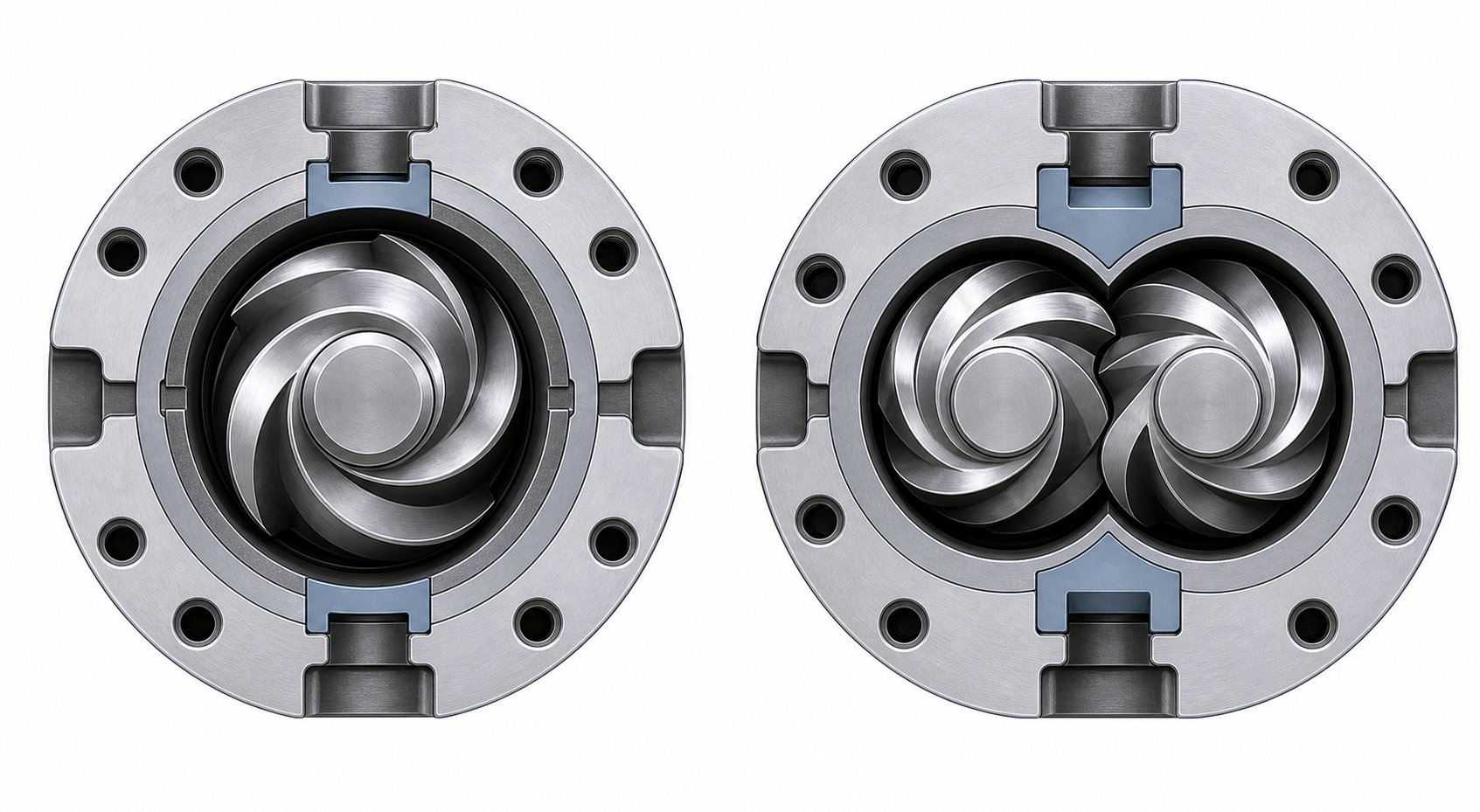
Twin-screw extruders use two intermeshing screws — either co-rotating (same direction) or counter-rotating (opposite directions) — to achieve positive displacement rather than friction-dependent conveying. This means the twin screw barrel can handle difficult feedstocks that a single screw would struggle with: fine powders, high-filler-load compounds, moisture-laden recycled flake, and reactive blends.
Co-rotating twins dominate compounding and reactive extrusion. Their modular design lets processors reconfigure screw elements — conveying segments, kneading blocks, reverse elements — along the twin screw and barrel assembly to tailor the shear profile for each recipe. Counter-rotating twins, typically run at lower speeds, excel where gentle, controlled conveying with minimal backflow is essential, such as PVC pipe and profile extrusion.
The key advantage is full-channel material transfer. As Frankland notes, the twin can transfer the entire channel of polymer from one screw to the other multiple times, applying high shear to a small fraction of the melt while keeping the bulk temperature low. A single screw simply cannot replicate that incremental approach.
Dispersive vs. Distributive Mixing in Both Systems
Every mixing challenge falls into one of two categories — and most real-world formulations require both.
- Dispersive mixing breaks down agglomerates, filler clusters, and oversized droplets by forcing material through high-stress regions. Imagine crushing a clump of pigment into its individual particles. In single screws, Maddock (LeRoy) mixers achieve this by channeling the entire melt over a narrow barrier flight. In twin screws, wide kneading blocks with full-disk geometry — like KBW elements — generate the high-shear forces needed.
- Distributive mixing spreads already-dispersed components uniformly throughout the melt without applying high stress. Think of evenly distributing those pigment particles so no color streaks appear. Pin sections and pineapple mixers handle this in single screws by repeatedly splitting and recombining the melt stream. In twin screws, narrow kneading elements and toothed mixing elements perform the same function with greater efficiency.
The critical difference is scale. A twin screw achieves both mixing types across multiple stages without the cumulative pressure-drop penalty that limits single-screw mixing to one or two sections.
| Criterion | Single-Screw Extruder | Twin-Screw Extruder |
|---|---|---|
| Material Conveyance | Friction-driven drag flow | Positive displacement via intermeshing screws |
| Mixing Capability | Basic melting and pumping; limited mixing sections available | Exceptional dispersive and distributive mixing through modular screw elements |
| Throughput Control | Sensitive to material friction and back-pressure | Largely independent of material friction; starve-fed operation common |
| Feedstock Flexibility | Best with uniform pellets of pre-compounded resin | Handles powders, flakes, high-filler loads, and inconsistent feedstocks |
| Capital Cost | Lower upfront investment | Significantly higher due to gearbox complexity and precision machining |
| Maintenance Complexity | Simpler — fewer wear components | Higher — intermeshing elements require precise alignment and monitoring |
| Barrel Configuration | Single bore; fixed screw geometry in most cases | Segmented twin screw barrel with modular, reconfigurable elements |
| Typical Applications | Film, pipe, profile, sheet from pre-compounded resins | Compounding, masterbatch, reactive extrusion, filled and reinforced compounds |
Note: Performance ranges overlap in some applications. The choice between systems depends on specific formulation complexity, required mixing intensity, and production economics.
Choosing between single and twin configurations is only one level of the decision. Within either platform, the screw design itself can evolve well beyond a basic general-purpose geometry — barrier flights, wave profiles, and specialized mixing elements each address processing problems that a standard helical channel cannot solve on its own.
Advanced Screw Designs Beyond General-Purpose Extruder Screws
A general-purpose screw with its three basic zones can handle a surprisingly wide range of polymers — until it can't. Output starts surging. Unmelted particles slip past the die. Color streaks refuse to disappear no matter how many barrel-zone adjustments you make. These are not random failures. They are symptoms of specific processing limitations baked into the GP geometry, and they drove decades of engineering innovation that produced an entirely different class of extruder screws and barrels. Each advanced design emerged because a real-world problem demanded a solution that no standard helical channel could deliver.
Barrier Screws and Solid-Bed Separation
The most persistent headache with GP screws in semi-crystalline polymer processing was solid-bed breakup. As the solid bed advanced through the transition zone, it would occasionally fracture into chunks — irregularly shaped pieces of unmelted resin that drifted into the melt pool and traveled downstream, causing output surging, pressure fluctuations, and gels or hard spots in the final product. The root cause was straightforward: a single flight could not reliably keep the solid bed intact while simultaneously allowing molten polymer to flow freely past it.
Barrier screws solved this by introducing a secondary flight — a second helical ridge running parallel to the primary flight — that physically separates the solid bed from the melt pool into two distinct channels. The clearance between this barrier flight and the barrel wall is deliberately set tighter than the main flight clearance, allowing only molten polymer to cross over into the melt channel while solid material stays confined in the solids channel. The result is a controlled, progressive melting process with far less risk of solid-bed disruption.
Two principal barrier designs dominate the landscape, each suited to different polymer requirements. As Jim Frankland of Frankland Plastics Consulting explains, the choice between them depends largely on the melting energy requirements of the polymer:
- Crossing (Maillefer) barrier: One of the earliest barrier designs, the Maillefer type features a barrier flight that crosses over the main flight, creating a solids channel that progressively narrows while the melt channel widens. It introduces no sudden restriction at the start of the barrier section, making it advantageous for hard or slippery polymers whose fragile solid beds resist reshaping. The crossing design also generates more head pressure thanks to its wider, shallower melt channel. Best fit: polymers with lower melting-energy requirements — low processing temperatures, low specific heats, and low shear-thinning behavior.
- Parallel (Barr-type) barrier: Introduced after the Maillefer, the parallel barrier runs a secondary flight alongside the primary flight without crossing it, creating a solids channel with roughly one-third more surface area than a crossing design of the same axial length. Since melting capacity is largely proportional to available surface area, parallel barriers deliver higher output with better melt quality for polymers that demand more energy to melt. Best fit: semi-crystalline polymers with higher melting points, higher specific heats, or significant shear-thinning characteristics — HDPE and PP being prime examples.
Modifications to both types continue to evolve. Dray-Lawrence variants use longer helix angles in the barrier section — increasing the lead by 25% or more — to pack more volume into the barrier zone for higher output, though Frankland notes the melting-capacity improvement per unit length is modest, typically less than 10%. The real gain is accommodating a wider solids channel that minimizes disruption at the barrier start. More nuanced design features, like decompression zones at the barrier entry or openings to accommodate early melting, help parallel barriers handle the geometry change that can otherwise destabilize fragile solid beds.
One important detail that separates good barrier screws from bad ones: the exit end of the solids channel. A closed-end design demands that melting is essentially complete before the channel terminates — otherwise solids plug the exit, causing pressure fluctuations and accelerated screw wear. An open-end design provides more tolerance but requires that something downstream — typically a mixing section — finishes the job.
Wave Screws and Energy-Efficient Mixing
Barrier screws dramatically improved melt consistency, but they did not address every limitation. Some processors found that while their extruder screws eliminated unmelts, the melt temperature ran higher than desired — extra shear from the barrier clearance added energy that was difficult to remove downstream. Wave screws emerged as an alternative philosophy: instead of separating solid from melt with a secondary flight, they use oscillating channel depths to force the melt across alternating peaks and valleys along the screw's metering section.
Imagine a channel floor that rises and falls in a controlled, sinusoidal pattern. As the melt passes over a peak (a shallow region), it experiences higher shear and is forced to redistribute across the channel width. As it drops into a valley (a deep region), shear decreases and the melt relaxes. This cyclic compression and expansion achieves thorough thermal and compositional mixing with significantly less total shear energy than a conventional barrier flight or dispersive mixer would impose.
The practical benefit is lower melt temperature at equivalent or better homogeneity — which translates directly into energy savings on both the extruder drive and the downstream cooling system. Wave screws are particularly well suited for processors running high-volume polyolefin lines where even a few degrees of melt-temperature reduction can yield measurable cost savings over millions of pounds of annual output.
Mixing Sections — Maddock, Pin, and Pineapple Elements
Neither barrier nor wave screws eliminate the need for dedicated mixing elements in every application. Color concentrates, additive masterbatches, and multi-component blends all benefit from a final mixing stage that either breaks down agglomerates or distributes minor components uniformly throughout the melt — and sometimes both. Mixing sections are modular additions that can be integrated into GP, barrier, or wave screws and barrels to target specific homogeneity problems.
The earliest and most widely recognized dispersive mixer is the Maddock (LeRoy/UCC) mixer. As Plastics Technology documents, this design dates to the late 1960s and channels the entire melt stream through a narrow clearance gap between inlet and outlet flutes. Material must pass over a barrier land — forcing high-shear stress on every polymer element — before it can exit. The result is aggressive dispersive mixing that breaks down remaining unmelts, pigment agglomerates, and gel particles. Modern spiral Maddock mixers incorporate features of both the original Maddock and Egan designs and remain among the most widely used dispersive elements today.
Distributive mixers take a fundamentally different approach. Rather than applying high stress, they split and recombine the melt stream repeatedly to create an exponentially increasing number of layers:
- Pin mixers: Rows of cylindrical pins protrude from the screw root into the channel, dividing the melt stream with each row. The number of layers grows exponentially with each successive row, overcoming the laminar-flow limitations that make natural mixing in a screw channel so sluggish. Pin mixers excel at blending components of significantly different viscosities but can introduce substantial pressure drop.
- Pineapple mixers: Similar to pin designs in their division-and-recombination principle, pineapple elements converge the divided streams at varying angles to create chaotic mixing patterns. They are especially effective for color homogenization — eliminating the streaks that plague masterbatch-colored products.
- Saxton mixers: A series of interrupted flights divide the melt into multiple channels with cross-connections between them. Saxton elements provide thermal homogenization with very low pressure drop, making them useful where mixing is needed but output loss must be minimized.
A critical insight from Frankland's analysis deserves emphasis: barrier screws paired with high-shear dispersive mixers are often a mismatch. If the barrier section is properly designed, melting should already be complete by the time material exits the solids channel. Adding a Maddock mixer after a well-functioning barrier section needlessly increases melt temperature, reduces output through added pressure drop, and wastes energy during both extrusion and downstream cooling. In most cases, a distributive mixer — pin, pineapple, or Saxton — is the better complement to a barrier screw, providing the final homogenization step without the thermal penalty.
- Barrier screw (Maillefer/crossing type): Separates solid bed from melt via a crossing secondary flight. Primary function: stable melting with minimal solid-bed disruption. Best fit: polymers with lower melting-energy demands, hard or slippery resins prone to bed instability.
- Barrier screw (Barr/parallel type): Separates solid and melt channels with a parallel secondary flight offering greater melting surface area. Primary function: high-output melting with consistent quality. Best fit: semi-crystalline polymers requiring high energy input — HDPE, PP, nylon.
- Wave screw: Oscillating channel depths create alternating compression and relaxation in the metering zone. Primary function: energy-efficient mixing and thermal homogenization at reduced melt temperatures. Best fit: high-volume polyolefin lines targeting lower energy consumption.
- Maddock/LeRoy dispersive mixer: Forces entire melt stream over a narrow barrier land for high-shear stress. Primary function: breaking down unmelts, gels, and pigment agglomerates. Best fit: GP screws processing resins with unmelt or agglomeration issues — use cautiously on barrier screws.
- Pin mixer (distributive): Rows of pins split and recombine the melt exponentially. Primary function: blending components of differing viscosities with minimal shear. Best fit: additive or filler distribution, post-barrier homogenization.
- Pineapple mixer (distributive): Angled converging channels create chaotic flow patterns. Primary function: color homogenization and streak elimination. Best fit: masterbatch coloring operations, barrier screws requiring final distributive blending.
Each of these advanced designs represents a specific engineering answer to a specific processing problem — but the question of which design to choose still depends on something none of them can change: the polymer itself. A barrier screw optimized for HDPE would overshear rigid PVC, and a wave screw tuned for PP may under-mix a heavily filled compound. That reality points toward a selection strategy built from the resin outward, matching screw architecture to the thermal and rheological personality of each material family.
How to Select the Right Plastic Extrusion Screw for Your Polymer and Process
Every polymer has a thermal personality. Some melt in a sharp, dramatic phase change. Others soften slowly, like butter left on a warm counter. A few degrade the moment shear forces exceed a narrow threshold. That personality — not a catalog of screw models — should be the starting point for every selection decision. So when a processor asks, "What plastic extruder screw do I need?" the most useful answer always begins with another question: "What resin are you running?"
Semi-Crystalline vs. Amorphous Polymer Requirements
The single most important distinction in screw selection is whether the polymer is semi-crystalline or amorphous, because their melting behaviors demand fundamentally different screw geometries.
Semi-crystalline polymers — PE, PP, PET, and nylon — have tightly ordered molecular chains that resist softening until they hit a well-defined melting point. At that temperature, the crystalline structure collapses rapidly, releasing latent heat and producing a sudden transition from rigid solid to low-viscosity melt. This sharp phase change has two direct consequences for screw design. First, the solid bed remains intact and dense through most of the feed and early transition zones, requiring a longer feed section to build a stable, well-compacted bed before compression begins. Second, the transition zone needs a higher compression ratio — typically 3:1 to 4:1 — to match the dramatic density change that occurs as crystals collapse into a fluid melt. A plastic extrusion screw designed for HDPE blown film, for example, benefits from a barrier design with a strong mixing section, since incomplete melting shows up immediately as gels in thin film.
Amorphous polymers — PS, ABS, PMMA, and PC — lack that ordered crystalline structure. Instead of a distinct melting point, they transition gradually through a glass-transition temperature range, softening progressively as heat accumulates. This gradual softening means the solid bed begins to deform and compact earlier in the screw channel, allowing a shorter feed zone and a longer, gentler transition zone. Compression ratios can stay lower — often 2:1 to 2.5:1 — because the density change between solid and melt is far less dramatic. Pushing an amorphous resin through a high-compression screw designed for polyethylene typically generates excessive shear heat, raising melt temperature well beyond the target and risking thermal degradation.
Shear-Sensitive and Thermally Sensitive Materials
Two polymer categories do not fit neatly into the semi-crystalline versus amorphous framework and deserve their own design considerations.
PVC is the classic shear-sensitive material. It does not truly melt in the conventional sense — it fuses through a gelation process where powder grains compact and interdiffuse under controlled heat and moderate shear. Excessive compression or aggressive screw geometry raises local temperatures beyond PVC's narrow processing window, triggering rapid degradation that releases hydrochloric acid, corroding everything it contacts. As industry specialists emphasize, rigid PVC processing demands a screw plastic extruder design that heats the material very evenly to approximately 150 degrees Celsius with all additives consistently distributed, then shears and heats to a final temperature of 180 to 200 degrees Celsius for optimal gelation. Compression ratios stay low — 2:1 to 2.5:1 — and twin-screw configurations often replace single screws entirely for PVC pipe and profile work, because their positive-displacement conveying avoids the friction-dependent heat spikes that single screws can produce.
PET is thermally sensitive in a different way. It melts cleanly at a well-defined temperature like other semi-crystalline resins, but it degrades rapidly through hydrolysis if moisture is present and through chain scission if residence time at elevated temperature is too long. A screw for PET needs moderate compression — around 2.5:1 — combined with careful temperature control and, ideally, a vented barrel section for devolatilization. Excessive L/D extends residence time and accelerates degradation, so PET screws tend toward 24:1 to 28:1 rather than the 30:1-plus lengths common for polyolefins.
Matching Screw Geometry to Your Extrusion Process
Polymer chemistry sets the boundaries, but the end-application process determines where within those boundaries the screw design should land. Different products impose distinct demands on melt pressure, temperature uniformity, and mixing quality — and a screw optimized for one process may underperform in another, even with the same resin.
- Blown film: Demands near-perfect melt homogeneity. At film thicknesses of 10 to 50 microns, a single unmelted particle becomes a visible gel. Barrier screws with mixing sections and L/D ratios of 30:1 or higher are close to essential, especially when processing LLDPE.
- Pipe extrusion: Requires high, stable melt pressure and excellent wall-thickness consistency. Moderate mixing is sufficient for pre-compounded resins, but PVC pipe lines typically use counter-rotating twin screws with L/D ratios that have trended from 20:1 three decades ago to 40:1 today for better homogeneity.
- Profile extrusion: Complex cross-sections demand tight temperature uniformity across the melt stream. Uneven melt temperatures cause differential shrinkage and warpage in window frames, trim, and technical profiles. Barrier or wave screws with distributive mixing sections help equalize thermal gradients.
- Sheet extrusion: Thickness is more forgiving than film, but optical clarity in clear sheet (PMMA, PETG, PC) still requires excellent melt quality. Moderate compression ratios and careful shear control prevent degradation-related haze.
- Wire coating: Speed is paramount — line speeds can exceed 1,000 meters per minute. The screw must deliver a stable, pressurized melt at extremely consistent rates with zero surging, favoring metering-zone-heavy designs.
- Filament extrusion: Desktop and small-scale filament lines — like the Filabot EX2 for research and prototyping or the Filabot EX6 for higher-throughput production — process a wide range of specialty polymers at relatively low volumes. Screw design for a filabot filament extruder or similar system must balance gentle, uniform melting across materials as varied as PLA, ABS, PETG, and nylon with precise diameter control, making versatile compression ratios and moderate L/D ratios critical.
| Polymer Family | Compression Ratio Range | Typical L/D Ratio | Special Design Notes |
|---|---|---|---|
| PE (HDPE, LDPE, LLDPE) | 3.0:1 - 3.5:1 | 28:1 - 33:1 | Barrier screw with mixing section strongly recommended for film; longer L/D for LLDPE |
| PP | 3.5:1 - 4.0:1 | 26:1 - 30:1 | High compression for sharp melt transition; barrier design improves consistency |
| PVC (rigid) | 2.0:1 - 2.5:1 | 24:1 - 40:1 | Low compression to prevent degradation; twin-screw preferred for pipe and profile |
| PET | ~2.5:1 | 24:1 - 28:1 | Moderate compression; short residence time; vented barrel recommended to avoid hydrolysis |
| Nylon (PA6, PA66) | 3.5:1 - 4.0:1 | 24:1 - 30:1 | Pre-drying essential; high melt fluidity allows steep compression zones |
| PS | 2.5:1 - 3.0:1 | 24:1 - 30:1 | Amorphous; gradual taper; avoid excessive shear that causes yellowing |
| ABS | 2.0:1 - 2.5:1 | 24:1 - 28:1 | Low compression protects rubber phase; distributive mixing for color uniformity |
| PC | 2.0:1 - 2.5:1 | 24:1 - 28:1 | Thermally sensitive; low shear and precise temperature control critical |
| PMMA | 2.0:1 - 2.5:1 | 24:1 - 30:1 | Degrades at high shear; optical applications require excellent melt clarity |
Note: Values shown are approximate guidelines compiled from industry references and resin supplier recommendations. Actual specifications depend on specific resin grade, additive package, throughput target, and end-product requirements. Always validate against resin supplier processing guides before finalizing screw geometry.
Selecting the right geometry and architecture gets the screw design right on paper — but the material that screw is made from determines how long that design keeps performing. Abrasive fillers, corrosive compounds, and simple metal-to-metal contact all erode screw surfaces over time, and the wrong metallurgy can cut a screw's useful life from years to months.
Screw Materials, Coatings, and Wear Resistance
A perfectly designed screw geometry means nothing if the metal underneath cannot survive the resin running through it. The moment a screw begins rotating inside its barrel, wear starts — and it never stops. What determines whether that wear remains negligible for years or destroys critical clearances in months is not the screw's channel depth or compression ratio. It is the metallurgy: the base material, the surface treatment, and how well both are matched to the specific polymer compound being processed.
This is a topic that too few processors evaluate carefully during the specification stage. The result? Premature screw and barrel failure, unplanned downtime, and replacement costs that dwarf whatever was saved by choosing a cheaper alloy.
Abrasive, Adhesive, and Corrosive Wear Mechanisms
Three distinct mechanisms attack extrusion barrels and screws during operation. Each one damages metal surfaces through a different physical or chemical pathway, and each demands a different metallurgical defense.
Adhesive wear occurs when two metal surfaces — the screw flight land and the interior bore of the extrusion barrel — momentarily come into direct contact. At the microscopic level, extremely high stresses develop at the contact points, briefly welding the two surfaces together before fracturing apart. As Plastics Technology describes, evidence of adhesive wear typically shows up as a burr or "rolling over" of the trailing edge of the flight land, or as scoring and galling on the barrel bore. Misalignment between the screw and barrel, poor concentricity, or running incompatible alloys accelerates this damage dramatically.
Abrasive wear is arguably the most common mechanism in plastics processing. Every time solid pellets are compressed against the barrel wall, the shearing action removes material from softer surfaces. With unfilled or low-viscosity polymers, the effect is gradual and manageable. But introduce glass fibers, mineral fillers like calcium carbonate or talc, or flame-retardant additives, and abrasive wear becomes aggressive. As SpecialChem's extrusion guide documents, fillers like mica and fiberglass cause severe wear beginning in the feed section — often visible by the third or fourth screw turn — because the composite resin is still in solid pellet form, and hard filler particles on pellet surfaces grind directly against unprotected steel. Some highly filled compounds can reduce screw and barrel useful life by 50% or more.
Corrosive wear attacks through chemical degradation rather than mechanical force. The gradual destruction of the metal surface by chemical reaction oxidizes and weakens the base material, leaving it vulnerable to accelerated mechanical wear. PVC processing is the classic example — thermal decomposition releases hydrochloric acid that aggressively attacks components with a high iron matrix. Fluoropolymers present similar challenges with hydrogen fluoride release at elevated temperatures. Corrosion does not just pit the surface; it removes the protective layer that surface treatments rely on, creating a compounding failure mode where chemical and mechanical wear feed each other.
Base Materials and Surface Treatment Options
Defending against these three mechanisms starts with the base material and the surface treatment applied to it. Choosing the right combination up front is far more cost-effective than replacing a failed screw mid-production.
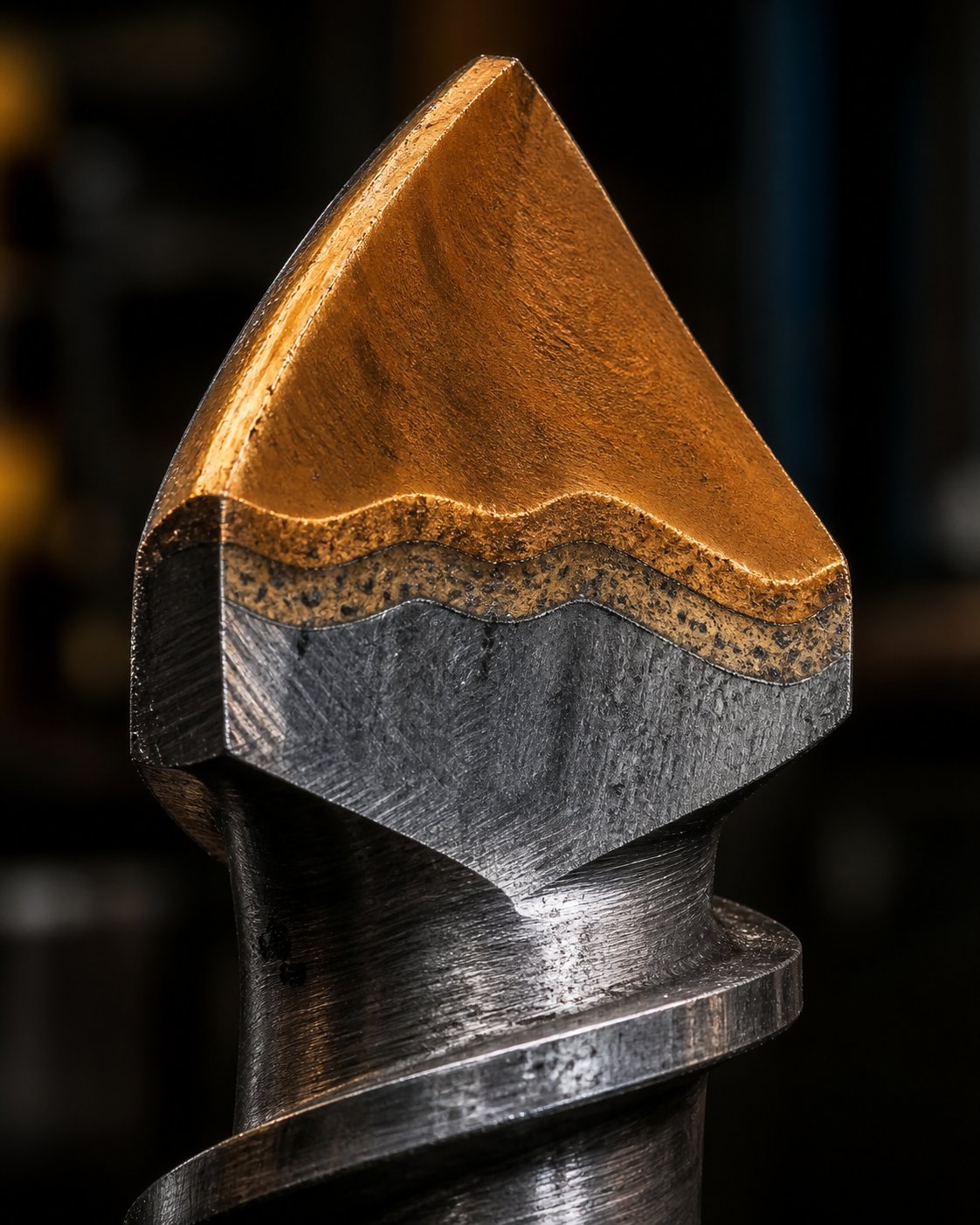
Nitrided steel remains the workhorse for general-purpose applications. The nitriding process diffuses nitrogen into the base material, creating a hard surface layer — typically 0.015 to 0.020 inches deep, reaching a hardness of approximately 60 Rc — without adding a separate coating. It is relatively inexpensive and provides excellent dimensional stability. The limitation? That thin hardened case will eventually wear through, especially with filled compounds, and once it does, the softer base metal beneath erodes rapidly. As SpecialChem cautions, when the nitrided layer wears away on a screw processing composites, the filler erodes the exposed base metal "like a hot knife through butter" — and the operator will not know it has happened unless the screw is pulled and visually inspected.
Tool steels offer higher base hardness and better wear resistance than standard nitrided steels, making them suitable for more demanding applications. However, as metallurgy specialists emphasize, the real performance of any steel grade depends on heat treatment and microstructure — not just the alloy specification on paper. Two extruder barrels made from the same material grade can perform very differently depending on how the heat treatment was executed.
Bimetallic barrel liners represent the premium tier for abrasion resistance. A wear-resistant alloy layer is bonded inside a steel barrel base through centrifugal casting, creating a composite structure where the tough outer shell handles structural loads while the hard inner liner resists erosion. Modern bimetallic technology incorporates tungsten-carbide particles suspended in the liner material, increasing barrel life by four to five times compared to older bimetallic formulations. For injection molding screws and barrels as well as extrusion barrels processing glass-filled or mineral-filled compounds, bimetallic construction is often the only cost-effective choice for sustained production.
Choosing Coatings Based on Your Compound
Beyond base materials and heat treatments, specialized coatings add targeted protection for the most demanding applications. The key is matching the coating to the dominant wear mechanism in your process — not simply choosing the hardest or most expensive option available.
- Nitriding (surface hardening): Diffuses nitrogen into the base metal for general-purpose case hardening. Primary protection: moderate abrasive and adhesive wear resistance. Best fit: unfilled or lightly filled polymers — PE, PP, PS — where wear is gradual and predictable.
- Chrome plating: Deposits a thin, chemically inert layer over the screw surface. Primary protection: corrosion resistance against chemically aggressive polymers. Best fit: PVC processing and fluoropolymer compounds where acid byproducts attack iron-based alloys.
- Tungsten carbide coatings (HVOF or spray-welded and fused): Applies an extremely hard carbide layer to critical wear surfaces. Primary protection: severe abrasive wear from high-filler-load compounds. Best fit: glass-fiber-reinforced resins, heavily mineral-filled compounds, and recycled materials with contaminants.
- Boron-based (boride) coatings: Creates a diffusion-bonded hard layer with excellent adhesion to the base metal. Primary protection: combined abrasion and corrosion resistance. Best fit: compounds that present both mechanical and chemical wear challenges simultaneously.
- Stellite and cobalt-based hardfacing: Applied to flight lands via welding overlay. Primary protection: adhesive wear resistance with good machinability. Best fit: flight-tip protection on screws running in hard bimetallic extrusion barrels where alloy compatibility matters.
A properly designed nitrided barrel may outperform a poorly selected bimetallic barrel. The difference lies in application understanding, not just product specification.
One critical detail that processors frequently overlook: the screw and barrel must be metallurgically compatible with each other. Running a soft flight hardfacing against one of the hardest bimetallic barrel liners creates a galling risk — the softer material shears and transfers onto the harder surface, accelerating damage on both components. Alloys with lower tungsten-carbide content may be easier to apply and finish, but they offer less wear resistance and have a greater tendency to gall against hard barrel liners. Getting this pairing right requires understanding both the injection molding barrel and screw combination and the extrusion barrel and screw combination as integrated systems — not as independent components purchased from separate catalogs.
For processors running abrasive or corrosive compounds — or those managing diverse equipment fleets spanning both extrusion and injection molding — working with a manufacturer that engineers application-specific materials and coatings eliminates much of the guesswork. NANHAIYA's screw barrel product center offers custom screw and barrel solutions built around the specific polymer compound, filler package, and operating conditions of each line, making it a practical sourcing option for replacement components where standard off-the-shelf metallurgy falls short.
Metallurgy keeps the screw performing over time — but even a well-protected screw can produce defective output if its geometry does not match the process. Surging, unmelts, streaks, and degradation are all symptoms that point back to specific screw-related root causes, each with its own diagnostic path and corrective strategy.
Troubleshooting Common Extrusion Screw and Barrel Problems
Your metallurgy is sound, your coatings are matched, and the screw just came back from reconditioning — yet the extrudate still looks wrong. Surging. Gels. Black specks. Streaks that refuse to disappear regardless of which barrel zone you adjust. These symptoms feel random on the shop floor, but each one traces back to a specific mismatch between screw geometry and what the polymer actually needs. Identifying the root cause in those terms — rather than chasing barrel temperature settings — is what separates a quick fix from weeks of frustrating trial and error.
Output Surging and Inconsistent Flow
Cyclic variation in die pressure or extrudate dimensions is one of the most common complaints on any extrusion line. You'll notice it as a rhythmic pulsing in the melt curtain, periodic weight fluctuations in cut lengths, or oscillating gauge readings on film lines.
The most frequent screw-related cause is solid-bed breakup in the transition zone. As Jim Frankland of Frankland Plastics Consulting explains, when the compression section is too gradual, melt can undermine the solid bed and destroy its structural integrity. In a conventional screw, those broken solid chunks simply convey forward and create inconsistent melting — output rises and falls as alternating slugs of fully molten and partially melted material reach the metering zone. In a barrier screw, the consequence is even more dramatic: solid fragments collect at the narrowing end of the solids channel, generating localized pressures so extreme they can bend the screw shaft and wear flights down to the root diameter. Frankland documented forces approaching 350,000 pounds on a single 8-inch barrier screw where this plugging occurred.
Inconsistent feeding compounds the problem. If pellets bridge in the hopper or feed throat, the screw starves intermittently, creating the same cyclic pressure behavior. As an immediate operational fix, verify hopper flow, check feed-throat cooling, and confirm that screw speed is not outpacing the solids-conveying capacity of the feed zone. Longer term, a screw redesign with better-matched compression characteristics — or a switch from a GP to a barrier geometry — eliminates the solid-bed instability at its source.
Unmelts, Gels, and Poor Homogeneity
Finding solid particles in the extrudate, visible gel spots on film, or temperature striations across a sheet cross-section all point to incomplete or uneven melting. The extruder screw and barrel are doing part of their job — conveying and pressurizing — but failing to deliver a thermally uniform melt to the die.
Several geometry-related root causes drive this defect. An L/D ratio that is too short does not give the polymer enough residence time or barrel-contact area to complete the melt transition — a common problem when a screw designed for one resin is repurposed for a polymer with higher melting energy requirements. A compression ratio that is too low produces insufficient shear in the transition zone, allowing partially fused pellets to slip through to the metering section. MD Plastics' engineering analysis confirms that when compression drops — whether by design or through wear that increases channel depth — melting shifts downstream, and the metering zone inherits material it was never designed to finish melting.
Worn flight lands worsen the picture. As clearance between the flight tip and the barrel bore increases, leakage flow over the flights grows, allowing unsheared material to bypass the high-shear region near the barrel wall. Operationally, a modest increase in screw speed can raise shear energy enough to compensate for early-stage wear. Adjusting mid-zone barrel temperatures upward supports conductive melting as a supplement. But these are band-aids. The lasting fix is specifying a screw and barrel combination with adequate L/D for the resin, the correct compression ratio, and — where mixing demands are high — a dedicated dispersive or distributive mixing section downstream of the transition zone.
Degradation From Excessive Shear
When the extrudate yellows, emits an unusual odor, develops black specks, or loses mechanical properties compared to the resin's data-sheet values, the polymer chains themselves are breaking apart. Three degradation mechanisms can be responsible — thermal, mechanical, and chemical — but in the context of screw geometry, mechanical degradation from excessive shear is the most directly controllable.
Imagine a metering channel that is too shallow for the resin's viscosity. Every revolution forces the melt through a gap so narrow that viscous dissipation spikes the local temperature far above the bulk melt reading. The barrel extruder thermocouple may read 220 degrees Celsius, but polymer near the flight tips can momentarily experience 260 degrees Celsius or higher — enough to trigger chain scission in shear-sensitive or thermally sensitive materials like PVC, PMMA, or PET. An overly aggressive compression ratio creates the same effect in the transition zone, converting mechanical energy into heat faster than the polymer can absorb it without degrading.
Operationally, reducing screw speed and lowering barrel temperatures in the metering zone can relieve the immediate symptoms. Adjusting backpressure downward, where system design allows, also reduces total shear input. For a permanent solution, deepening the metering channel and softening the compression profile bring mechanical energy input in line with the resin's thermal stability window. As MBPlastiPro's degradation guide emphasizes, streamlining the melt path to eliminate stagnation zones and reducing residence time at peak temperature are the core strategies for eliminating degradation at its source.
| Defect | Likely Screw-Related Cause | Operational Fix | Design Fix |
|---|---|---|---|
| Output surging (cyclic flow variation) | Solid-bed breakup in transition zone; too-gradual compression; inconsistent feeding | Verify hopper flow and feed-throat cooling; adjust screw speed to match solids-conveying capacity | Redesign compression profile to match polymer melting rate; upgrade to barrier screw geometry |
| Unmelts in extrudate (solid particles past the die) | Insufficient L/D ratio; compression ratio too low for the resin; worn flight lands increasing leakage flow | Increase screw speed slightly to raise shear energy; raise mid-zone barrel temperatures | Specify longer L/D screw; increase compression ratio to match polymer; add dispersive mixing section |
| Poor melt homogeneity (streaks, temperature variation, gels) | Inadequate mixing capability; no mixing section on GP screw; worn screw allowing bypass flow | Increase backpressure; fine-tune temperature profile to prevent premature melt pooling | Add Maddock (dispersive) or pin/pineapple (distributive) mixing section; consider barrier screw with mixing element |
| Polymer degradation (yellowing, black specks, reduced properties) | Metering channel too shallow causing excessive shear; compression ratio too aggressive; stagnation zones in screw or die | Reduce screw speed and metering-zone barrel temperatures; lower backpressure | Deepen metering channel; soften compression ratio; streamline melt path to eliminate dead spots |
Note: Many defects share overlapping symptoms. Always confirm the root cause through screw inspection and melt-quality measurement before committing to a design change.
A troubleshooting chart identifies what went wrong — but it does not tell you whether the right response is a process adjustment, a screw rebuild, or a completely new specification. Making that call requires a structured evaluation of the screw's current condition, a clear understanding of what the replacement should look like, and an honest accounting of how screw cost stacks up against the processing losses it is meant to eliminate.
How to Evaluate, Specify, and Source Your Next Extrusion Screw
Knowing what went wrong with your current screw is only half the battle. The other half — the part that actually saves money and prevents repeat failures — is translating that knowledge into a specification document precise enough that the replacement screw arrives ready to perform from its first rotation. Whether you are running a brand-new line, maintaining a fleet of used extruders acquired through equipment resellers, or rebuilding a legacy Davis-Standard extruder that has been producing pipe for two decades, the evaluation and specification process follows the same logical sequence.
Evaluating Screw Performance and Wear Status
Before ordering anything, you need a clear picture of where your current screw actually stands. That means measuring — not guessing — two things: geometric condition and process performance.
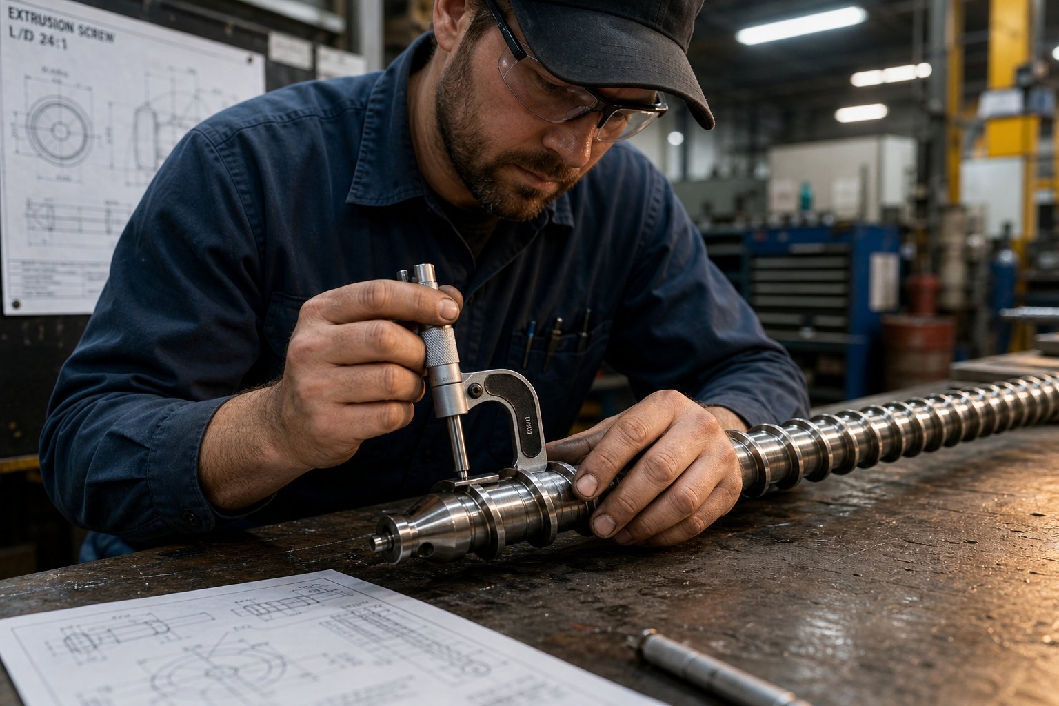
Start by pulling the screw and measuring flight outside diameter at multiple points along its length using a micrometer or laser measurement tool. Compare those readings to the screw's original dimensional drawing. As Mark Spalding and Tim Womer document in Plastics Technology, flight clearance when new is typically the nominal screw diameter divided by 1,000 — so a 3.5-inch screw starts with roughly 0.004 inches of clearance per side. Any increase beyond that baseline reflects wear. While the barrel is empty, measure its bore diameter with a telescoping gauge at the same axial positions. An iron-based bimetallic barrel liner typically lasts for the service life of three screws, but confirming bore condition prevents the expensive mistake of installing a new screw inside a worn barrel.
Simultaneously, document your process baselines: specific rate (output divided by screw speed), discharge melt temperature, drive motor amperage, and pressure stability at the die. These metrics reveal whether your problems are wear-driven or design-driven. A screw that once delivered 150 kg/hr at 80 rpm but now requires 95 rpm for the same output — with discharge temperature climbing from 236 degrees to 246 degrees — is exhibiting classic wear symptoms. Spalding and Womer's research shows that in a blown film application, this level of deterioration can force a 13% rate reduction to maintain acceptable melt temperature, directly cutting line profitability and capacity.
The replacement trigger is ultimately an economic calculation. Some processors replace when flight clearance reaches four times the original value. Others wait until hard facing is completely worn through. The most rigorous approach? Replace when the economics of lost output, elevated energy consumption, and quality risk exceed the cost of a new or refurbished screw. Noncritical applications like corrugated pipe can tolerate more wear; precision medical or optical film lines demand replacement much sooner — sometimes at just two times the original clearance.
One practical tip from Womer's decades of screw design experience: keep a spare screw in storage. When the working screw reaches end of life, install the spare immediately and send the worn unit out for refurbishment — but never refurbish the same screw more than three times. Each welding cycle for new hard facing deteriorates the base material, increasing the risk of delamination between the overlay and the substrate.
Specifying a New or Replacement Extrusion Screw
With wear status documented and the root cause identified — design limitation, material mismatch, or simple end-of-life erosion — the specification process becomes a structured checklist. Missing any element leads to a screw that arrives dimensionally correct but functionally wrong for your application.
- Barrel inside diameter (bore): Measure the actual barrel bore — not the nominal size on the machine nameplate. Worn barrels may have an oversized bore that requires a screw with correspondingly larger flight OD to restore proper clearance.
- L/D ratio: Confirm the functional screw length and target L/D. If your current screw is too short for the resin — a common finding when switching materials on used single screw extruders or repurposed lines — this is the time to correct it.
- Compression ratio: Specify the feed-depth-to-metering-depth ratio based on the primary polymer being processed. Refer to resin supplier processing guides or established engineering references like Rauwendaal's Polymer Extrusion for validated starting points.
- Screw design type: Decide whether a general-purpose, barrier, or wave design best fits your melting and mixing requirements. Factor in whether a dedicated mixing section — Maddock, pin, or pineapple — is needed downstream.
- Base material: Select nitrided 4140 steel for lightly filled commodity polymers, tool steels like D2 or H13 for moderately abrasive compounds, or powder metallurgy grades (CPM 9V, 10V) for severely abrasive glass-filled or mineral-filled service. As sourcing data confirms, CPM 10V screws routinely exceed 20,000 hours of service life in 40-60% mineral-filled HDPE — compared to roughly 3,000 hours for nitrided 4140 in the same application.
- Surface treatment and coatings: Match the coating to the dominant wear mechanism. Nitriding for general-purpose duty, chrome plating or nickel-based liners for corrosive PVC service, tungsten carbide HVOF coatings for severe abrasion, Stellite hardfacing for flight-tip protection against hard bimetallic barrels.
- Application details: Provide the screw manufacturer with full process context — polymer type, filler content, throughput target, melt temperature range, die type, and end product. A screw specified for "PE pipe" performs differently than one specified for "LLDPE blown film" even if both run polyethylene, because the mixing and pressure demands differ significantly.
The choice between OEM replacement screws and aftermarket custom-engineered alternatives is worth considering carefully. OEM parts guarantee dimensional compatibility with your machine, but aftermarket specialists often offer superior metallurgy, application-specific design modifications, and faster lead times — particularly valuable for operations running a diverse equipment fleet that spans both extrusion and injection molding platforms. For processors, equipment manufacturers, and maintenance teams seeking that kind of flexibility, NANHAIYA's screw barrel product center provides custom and replacement screw and barrel solutions engineered for specific polymer compounds across both extrusion and injection molding equipment — making it a practical next step alongside consulting your resin supplier and reviewing foundational engineering references.
If you are sourcing a used twin screw extruder or picking up a Davis Standard extruder for sale on the secondary market, pay particular attention to the condition of the existing screw elements. The equipment may be mechanically sound, but the screws inside it were designed for someone else's resin, filler package, and throughput target. Specifying a replacement screw matched to your process — rather than inheriting the previous owner's compromise — is often the single highest-return investment on a used machine.
Balancing Screw Cost Against Processing Economics
"How much do screws cost?" is one of the most frequently searched questions in this category — and one of the hardest to answer with a single number. Pricing depends on screw diameter, L/D ratio, design complexity (GP versus barrier versus wave with mixing sections), base metallurgy, hardfacing overlay, and surface treatment. A general-purpose nitrided screw for a 60 mm extruder might cost a few thousand dollars. A CPM 10V bimetallic screw with Stellite-overlaid flights for a 150 mm compounder processing glass-filled nylon can approach $25,000 to $35,000. Requesting quotes from specialized manufacturers — with your full specification checklist in hand — is the only reliable way to get accurate pricing for your application.
The more important question, though, is not what a screw costs to buy. It is what a screw costs to run. A well-designed screw matched to your polymer and process versus a poorly matched one can differ by 5% to 10% in overall line energy consumption, according to Jurry Extrusion's energy analysis. On a 250 kW extruder running 6,000 hours per year, even a 5% efficiency gap translates to $7,500 annually at $0.10/kWh — and that figure climbs steeply with volatile energy prices. Factor in the output loss from worn clearances (8% to 15% rate reduction as clearance widens from 0.1 mm to 0.5 mm), unplanned downtime costs ($12,000 to $40,000 per shutdown event for a continuous line), and scrap from quality excursions, and the total cost of ownership calculation overwhelmingly favors the premium screw.
Consider a concrete example from documented sourcing data: a 75 mm twin-screw compounding line processing 40% glass-filled PA66. A standard nitrided screw set costs roughly one-quarter of a CPM 10V bimetallic assembly — but requires replacement every 4,500 hours versus 18,000+ hours for the premium option. Over a 36-month production horizon, the cheaper set drives four replacement cycles while the premium set drives one. When downtime, labor, quality losses, and energy penalties are included, the premium assembly delivers a 62% reduction in total operating cost despite its higher purchase price.
US extruders — whether brand-new installations or refurbished legacy machines — face the same economic reality. The screw and barrel together represent under 5% of a typical extruder's capital cost, yet they govern 60% to 75% of its lifetime operating economics. Optimizing for purchase price alone is, as multiple case studies consistently demonstrate, the most expensive long-term strategy a processor can adopt.
The cheapest screw to buy is almost never the cheapest screw to operate. Total cost of ownership over 36 months — not the line item on the purchase order — determines which specification actually saves money.
Whether you are replacing a worn screw on a single production line or standardizing specifications across a multi-machine facility, the path forward is the same: measure what you have, identify what failed and why, specify the replacement with full process context, and evaluate cost over a real production horizon rather than a procurement spreadsheet. That discipline — applied consistently — turns the extrusion screw from a recurring maintenance headache into the performance asset it was always designed to be.
Frequently Asked Questions About Extrusion Screws
1. What are the three zones of an extrusion screw and what does each one do?
Every extrusion screw is divided into feed, transition (compression), and metering zones. The feed zone uses deep channels to intake solid pellets and convey them forward through friction against the barrel wall. The transition zone gradually reduces channel depth to compress the polymer, generating frictional heat that initiates and completes melting. The metering zone has the shallowest channel, applying uniform shear to homogenize the melt and build stable pressure for the die. Zone length proportions vary by polymer type — semi-crystalline resins like PE typically need longer feed zones, while amorphous polymers like ABS benefit from longer, gentler transition zones.
2. How do I choose the right compression ratio for my polymer?
Compression ratio — feed-zone channel depth divided by metering-zone channel depth — must match your polymer's melting behavior. Semi-crystalline polymers like HDPE and nylon undergo sharp phase changes and need higher ratios (3:1 to 4:1) to accommodate the dramatic density shift from solid to melt. Amorphous resins like polycarbonate or ABS soften gradually, performing well at lower ratios (2:1 to 2.5:1). Shear-sensitive materials like PVC require deliberately low ratios to prevent thermal degradation. Always cross-reference your chosen ratio with the resin supplier's processing guide, since pellet shape, bulk density, and additive packages also influence the ideal value.
3. What is the difference between a barrier screw and a general-purpose screw?
A general-purpose (GP) screw uses a single helical flight across all three zones, which can lead to solid-bed breakup, output surging, and unmelts — especially with semi-crystalline polymers. A barrier screw introduces a secondary flight that physically separates the unmelted solid bed from the molten polymer pool. This controlled separation ensures progressive, stable melting and significantly reduces gels and pressure fluctuations. Two main barrier types exist: crossing (Maillefer) designs work best for polymers with lower melting-energy demands, while parallel (Barr-type) designs offer greater melting surface area for high-energy polymers like HDPE and PP.
4. How do I know when my extrusion screw needs to be replaced?
Measure the screw's flight outside diameter at multiple points and compare readings to the original dimensional drawing. Flight clearance when new is typically the nominal diameter divided by 1,000. If clearance has doubled or tripled, worn flights are allowing leakage flow that reduces output and degrades melt quality. Process indicators also matter: if specific output (kg/hr per rpm) has dropped, melt temperature has risen at the same speed, or drive amperage has changed significantly, wear is likely the cause. The replacement trigger is ultimately economic — replace when lost output, higher energy use, and scrap costs exceed the price of a new screw. For processors needing custom replacements matched to specific compounds, manufacturers like NANHAIYA (nhyscrews.com/products) engineer application-specific screw and barrel solutions.
5. Why does screw metallurgy matter and what coatings should I use?
Screw metallurgy determines how long your geometry maintains its designed clearances under real processing conditions. Three wear mechanisms attack screws: abrasive wear from fillers like glass fiber and calcium carbonate, adhesive wear from metal-to-metal contact between the flight tip and barrel bore, and corrosive wear from chemically aggressive polymers like PVC. Nitrided steel handles unfilled commodity resins well. Chrome plating protects against corrosion in PVC service. Tungsten carbide coatings (HVOF-applied) resist severe abrasion from glass-filled or mineral-filled compounds. For extreme cases, CPM 10V powder metallurgy screws can last over 20,000 hours in heavily filled applications versus roughly 3,000 hours for standard nitrided steel — making premium metallurgy far cheaper over a full production cycle.
Written by
Nanhaiya Technical Team
Zhoushan Nanhaiya Plastic Machinery Co., Ltd.
The Nanhaiya technical team supports screw and barrel manufacturing projects through application review, technical communication, custom manufacturing coordination, and production and quality control.
Discuss Your Application
Related Articles
More insights on screw barrel technology and plastics processing.

Extruder Machine Decoded: From Raw Pellet To Finished Product
Oct 6, 2026
Learn how an extruder machine works, compare single-screw vs. twin-screw types, and get expert guidance on specs, troubleshooting, and selection.
Read Article
PE Pipe Making Machine Decoded: From Raw Resin to Flawless Pipe
Oct 4, 2026
Learn how a PE pipe making machine works, from resin to finished pipe. Covers components, material grades, automation, troubleshooting, and buyer selection tips.
Read Article
PVC Profile Making Machine Decoded: From Raw Resin To Profit
Oct 3, 2026
Learn how a PVC profile making machine works — extrusion process steps, key technical parameters, die design, calibration methods, maintenance, and total cost of ownership.
Read ArticleLooking for something else?
Search by material, symptom or product and jump straight to the relevant page.
These are navigation suggestions based on keyword matching — not a quotation, not a delivery commitment, and not a substitute for engineering review. Final specification is confirmed by our engineers against your drawings and processed material.
Need help with screw barrel selection?
Share your machine model, processed material and application. Our team can help with pricing and technical support.