

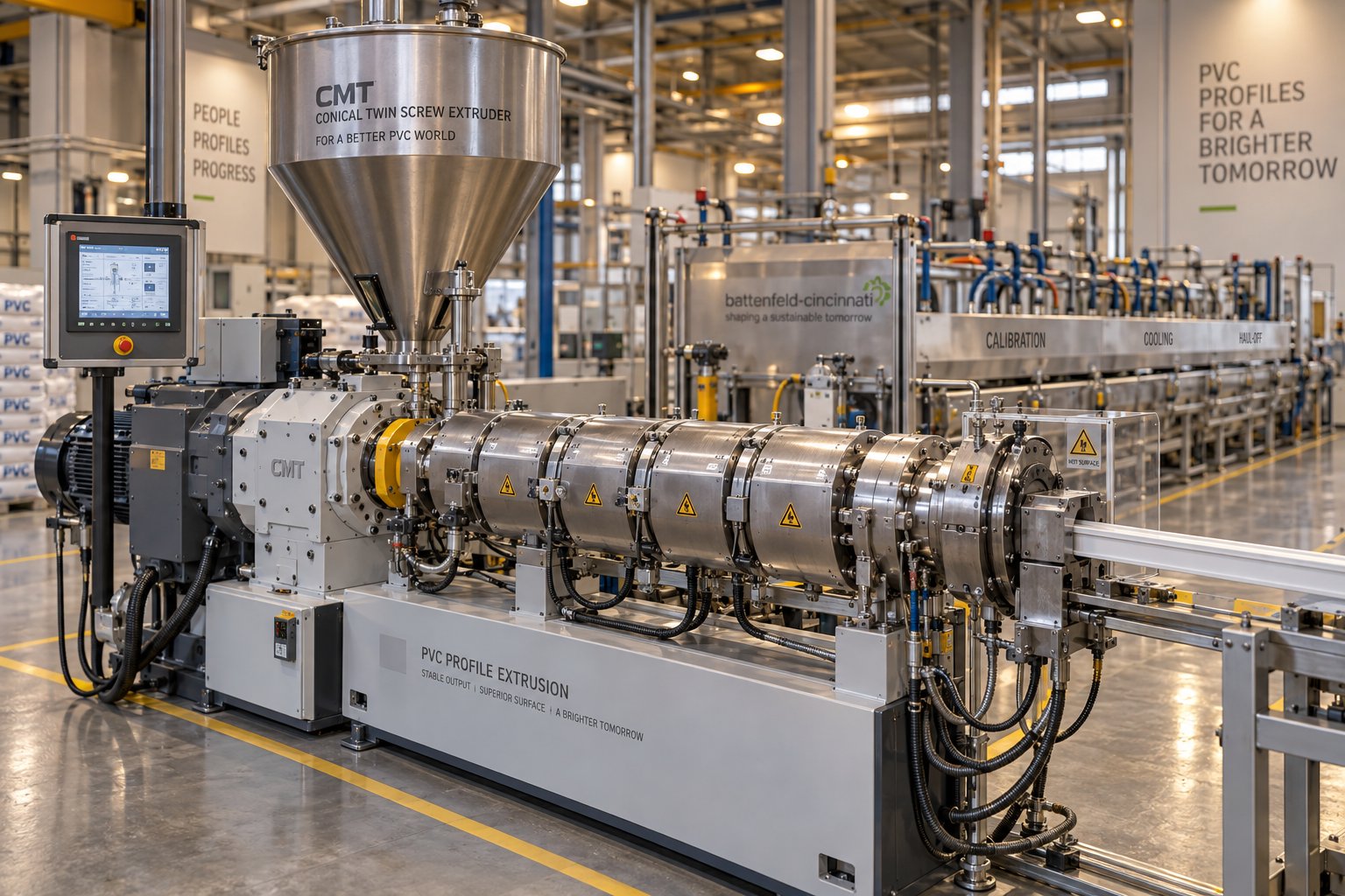
什么是锥形双螺杆挤出机?它为何如此重要?
想象一下,两个锥形螺杆在一个从一端到另一端逐渐变细的筒体内相互啮合。随着螺杆旋转,PVC粉末原料从宽端被吸入,逐渐被压缩、熔化,然后从窄端被挤出,形成均匀的熔体,准备成型为成品型材。这基本上就是锥形双螺杆挤出机的工作原理——它正是每年数百万个PVC窗框、门系统、线槽和建筑装饰件背后的主力军。
锥形双螺杆挤出机是一种PVC挤出机,它使用两个锥形、反向旋转的啮合螺杆,在收敛的料筒内熔化、均质化并将PVC化合物输送成连续的型材,同时最大限度地减少热降解。
定义和基本工作原理
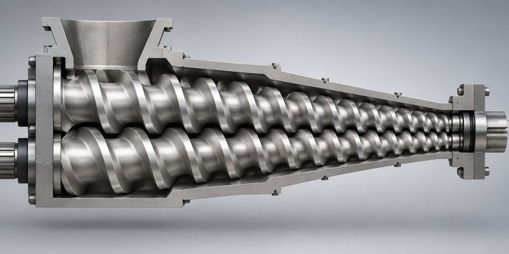
这款PVC型材挤出机的显著特点是其锥形设计。螺杆进料端直径较大,向出料端逐渐变小。当物料沿螺杆移动时,通道容积的减小会产生自然的压缩效果——无需复杂的螺杆元件结构。每排螺杆与机筒之间形成的C形通道持续收缩,通过轻柔可控的压力而非强烈的机械剪切力来压实和熔化PVC粉末。在出料区,较小的螺杆直径意味着较低的圆周速度,这直接降低了熔体最易发生降解部位的剪切加热。
为什么PVC型材生产商依赖这台机器
PVC材料对热极其敏感。在接近加工温度时,它就开始危险地分解,而过大的剪切力只会加速这种分解。锥形双螺杆挤出机通过其独特的设计解决了这个问题——其锥形结构可在进料端为大块干混粉末提供高扭矩,同时保持低剪切力和低温出料。这使其成为生产各种硬质PVC型材的行业标准,产品范围涵盖复杂的多腔窗框到简单的踢脚板。
接下来的章节将逐层剖析机器与材料之间的关系——从决定锥形几何形状优势的聚合物科学,到螺杆和料筒设计变量,再到加工参数、故障排除和维护最佳实践,从而确保您的生产线零缺陷运行。
为什么锥形螺杆几何形状是专为PVC化合物设计的
Most thermoplastics give you room to play with temperature and speed before things go wrong. PVC does not. It is one of the few commodity polymers where the gap between "not melted enough" and "already degrading" is razor-thin. Understanding this chemistry is the key to understanding why a conical screw extruder — and not just any twin screw extruder plastic processors might consider — became the dominant platform for rigid PVC profiles.
PVC Thermal Degradation and Shear Sensitivity
Rigid PVC has a glass transition temperature (Tg) in the range of roughly 80-85 °C, yet it does not flow like a conventional thermoplastic melt. Instead, PVC dry-blend particles must be compacted, fused, and homogenized at temperatures typically between 170 °C and 200 °C. The problem? PVC begins to degrade through a process called dehydrochlorination at temperatures uncomfortably close to that processing window.
During dehydrochlorination, hydrogen chloride (HCl) gas is released from the polymer chain, leaving behind conjugated carbon-carbon double bonds known as polyene sequences. Research published in Polymer Degradation and Stability confirms that this polyene formation is responsible for the yellowing and discoloration observed in degraded PVC, and that the process is autocatalytic — meaning once it starts, HCl itself accelerates further degradation. Even stable radicals can form at relatively modest temperatures, indicating that radical degradation mechanisms remain active across a broad range of conditions.
Here is where shear enters the picture. Every bit of mechanical energy the screws put into the material converts to heat. In a twin screw extruder plastic processing setup, excessive screw speed or aggressive compression generates frictional heat that pushes melt temperature past the safe limit — triggering dehydrochlorination, gas evolution, black specks, and structural weakness in the finished profile. The practical takeaway is straightforward: PVC demands a plasticization strategy built on controlled compression and minimal shear heating, especially in the metering zone where the material is fully molten and most vulnerable.
How Conical Geometry Solves the PVC Processing Challenge
Picture two screws whose diameters shrink steadily from feed end to discharge end. A typical conical twin screw extruder for PVC might use a 65/132 size designation, meaning the screws taper from 132 mm at the intake to 65 mm at the output. This taper does two things simultaneously that parallel designs struggle to replicate in a single mechanical package.
First, high torque where you need it most. The large feed-end diameter provides a substantial screw root area and wide flight channels. Bulky PVC dry-blend powder — low in bulk density and difficult to convey — is grabbed efficiently, and the large diameter delivers the torque necessary to compact it. As PVC processing specialists have noted, the plasticizing capacity at the feed section of a conical machine can match that of a much larger parallel extruder because the effective working diameter at intake is significantly bigger than the nominal machine size suggests.
Second, low shear where the melt is most sensitive. As material advances toward the smaller-diameter discharge end, circumferential screw speed drops proportionally. Lower tip speed means lower shear rate, which means less frictional heat generation right at the stage where the PVC compound is fully fused and most prone to thermal degradation. The smaller metering zone also reduces the axial force on the screws, enabling pressure buildup with less mechanical stress on the material. The result is lower die swell, lower degradation risk, and a more dimensionally stable extrudate leaving the die.
In conical machines, the plasticizing rate is primarily controlled by adjusting screw and barrel temperatures rather than relying on shear input. This thermal-dominant control strategy contributes to significantly lower motor amperage and better power economy at higher RPM — a practical advantage that compounds over thousands of production hours.
Parallel twin screw extruders take a different approach. Their constant diameter along the entire barrel length means shear rate and circumferential speed remain uniform from feed to discharge. While parallel designs can offer a wider processing window and greater screw design freedom — advantages that matter in large-diameter pipe extrusion — they require more sophisticated screw element configurations to manage shear in heat-sensitive applications. For profile extrusion, where compact footprint, gentle plasticization, and tight thermal control are priorities, the conical twin screw extruder for PVC remains the preferred architecture.
| Parameter | Conical Twin Screw Extruder | Parallel Twin Screw Extruder |
|---|---|---|
| Shear Rate Profile | Decreases from feed to discharge — lowest shear at melt zone | Relatively uniform along barrel length |
| Compression Method | Natural taper creates progressive compression without complex screw elements | Achieved through screw pitch variation and element configuration |
| Torque Capacity at Feed | High — large-end diameter provides substantial root area for torque transmission | Defined by constant screw diameter; gearbox improvements have closed the gap |
| Barrel Footprint | Compact — converging barrel is shorter for equivalent plasticizing capacity | Longer barrel needed; easier to extend length for higher output |
| Screw Design Freedom | More limited by fixed taper geometry | Greater flexibility — longer screw length available for mixing and pressure zones |
| Processing Window | Can be narrower; optimized for heat-sensitive compounds | Can be wider; more forgiving for varied formulations |
| Suitability for Heat-Sensitive Polymers (PVC, CPVC) | Excellent — purpose-built for minimal shear heating at discharge | Good with proper screw design, but requires more careful configuration |
| Venting Flexibility | Limited positioning options | Better — allows early vent placement for degassing |
Neither design is universally superior. Parallel extruders have earned a strong position in large-diameter pipe production where output scalability and screw design flexibility outweigh the conical machine's compactness. But for rigid PVC profile extrusion — where thermal sensitivity, compact line layouts, and gentle plasticization define success — the conical screw extruder's tapered geometry is an engineering solution precisely matched to the polymer's chemistry.
Of course, geometry alone does not guarantee a perfect profile. The specific dimensions of those tapered screws — their L/D ratio, compression ratio, flight depth, and the metallurgy of the barrel protecting them — determine whether the machine delivers consistent quality or slowly drifts toward defects as components wear.
Screw and Barrel Design Variables for PVC Processing
The tapered profile of a conical screw extruder provides the foundation, but it is the finer dimensional details — ratios, angles, flight geometries, and barrel surface treatments — that determine whether your twin-screw extruder machine delivers flawless PVC profiles shift after shift or slowly drifts toward inconsistency. Think of these variables as the tuning knobs of your plasticizing system. Set them correctly and you get uniform melt quality at target throughput. Get them wrong, and no amount of downstream adjustment will compensate.
L/D Ratio and Compression Ratio Explained
The length-to-diameter ratio (L/D) of a conical twin screw is calculated using the larger feed-end diameter as the reference. A typical conical machine for PVC profiles operates with an L/D between roughly 22:1 and 26:1 — notably shorter than many parallel designs. Why does that matter? Because L/D directly governs residence time, the total duration PVC spends inside the heated barrel. Longer residence time allows more thorough melting and mixing, but for a heat-sensitive polymer like PVC, it also increases the window for thermal degradation. As screw parameter research emphasizes, thermally sensitive polymers generally benefit from a shorter L/D ratio to limit degradation risk while still achieving complete plasticization.
Compression ratio tells a complementary story. In a conventional single screw extruder, compression ratio is the volume of the first feed-zone flight channel divided by the volume of the last metering-zone flight channel. In a conical twin screw barrel design, the taper itself creates compression — the channel volume shrinks naturally as the screw diameter decreases from feed end to discharge end. Rigid PVC powder typically requires a compression ratio in the range of 3:1 to 4:1, while pre-pelletized rigid PVC compounds can work well at 2:1 to 3:1. Selecting the right ratio ensures the dry-blend powder is fully compacted and air is expelled before the material enters the intensive plasticizing zone.
Beyond these two ratios, flight geometry plays a critical role. You will encounter three primary approaches:
- Constant pitch, variable depth — the most common configuration for PVC, where flight depth decreases along the screw length while pitch stays fixed. This design promotes good barrel contact and heat transfer.
- Variable pitch, constant depth — pitch narrows progressively to create compression, sometimes used when specific mixing characteristics are needed.
- Variable pitch and variable depth — a hybrid approach that gives screw designers the most control over shear and compression profiles, though at higher manufacturing cost.
Flight depth deserves special attention. A deeper feed-section groove enhances conveying capacity for low-bulk-density PVC powder, but if the groove is too deep it weakens the screw root, increasing the risk of shear failure under torque. In the metering section, shallower grooves raise shear rates and improve final melt homogeneity — yet excessively shallow channels restrict output volume. The balance point depends on the specific profile geometry and formulation you are running.
Barrel Metallurgy and Wear Protection
Even the most precisely engineered screw geometry degrades without the right barrel to protect it. Rigid PVC profile compounds almost always contain calcium carbonate (CaCO3) filler, sometimes at loading levels of 15 to 40 parts per hundred resin. These mineral particles are mildly abrasive on their own; add titanium dioxide pigment for white profiles or antimony trioxide in flame-retardant formulations, and wear rates climb further. Meanwhile, HCl released during PVC processing introduces a corrosive component that attacks unprotected metal surfaces — a dual threat that barrel longevity research identifies as the primary reason standard carbon-steel barrels fail prematurely in PVC service.
Two surface treatment strategies dominate the industry:
- Nitriding — a thermochemical diffusion process that hardens the barrel bore surface to approximately 900-1100 HV. Nitrided steel barrels are cost-effective for standard PVC compounds with moderate filler loading and remain the baseline choice for many profile producers.
- Bimetallic lining — a centrifugally cast alloy sleeve, typically nickel-rich boron alloy with tungsten carbide or molybdenum boride phases, bonded inside the barrel bore. Bimetallic barrels offer superior abrasion and corrosion resistance and are the preferred option for heavily filled compounds or lines running 24/7 where unplanned downtime is especially costly.
Screw flight surfaces receive similar attention. Hard-facing with tungsten carbide or applying alloy coatings such as Colmonoy 56 or Colmonoy 83 protects the flight crests — the point of closest contact with the barrel wall and the area that wears fastest. When clearance between screw flights and barrel bore increases beyond acceptable limits (typically beyond 0.1-0.6 mm), melt backflow increases, plasticizing efficiency drops, and output consistency suffers.
Barrel material selection is not a one-time purchase decision — it is a long-term cost factor. A nitrided barrel running a high-CaCO3 compound may need replacement in 12 to 18 months, while a bimetallic alternative in the same application can last two to three times longer. Over a five-year horizon, the total cost of ownership — including downtime, scrap, and energy waste from worn components — often favors the higher-specification barrel.
Here is a consolidated view of the critical conical twin screw barrel design variables that PVC profile producers should evaluate when specifying or replacing components:
- Screw diameter pair (large-end / small-end, e.g., 65/132, 55/110)
- Taper angle — determines the rate of compression and shear reduction
- L/D ratio — balances residence time against degradation risk
- Compression ratio — matched to feed material form (powder vs. pellet) and bulk density
- Flight geometry — pitch variation, flight depth, and number of flights
- Barrel surface treatment — nitriding for standard duty, bimetallic lining for heavy-fill or high-uptime demands
- Screw flight hard-facing — tungsten carbide or alloy overlay for wear protection at the flight crest
Sourcing high-quality replacement or custom conical twin screw barrels with proper metallurgical treatments is essential for maintaining consistent plasticizing performance. Suppliers like NANHAIYA, who specialize in conical twin screw barrels for PVC profile and pipe applications, engineer their components with application-matched surface treatments — ensuring extended service life for producers running heavily filled compounds where wear and corrosion act simultaneously.
Getting the hardware right is only half the equation. The same screw and barrel set can produce vastly different results depending on how you set your barrel temperatures, screw speed, and melt pressure — the processing parameters that translate mechanical design into finished profile quality.
Critical Processing Parameters for PVC Profile Extrusion
A perfectly engineered conical screw and barrel set is only as good as the parameters an operator dials into it. Barrel temperatures, screw speed, and melt pressure form a triangle of interdependent variables — change one, and the other two shift in response. Mastering these relationships is what separates a PVC extrusion machine that delivers flawless profiles from one that fights surface defects and dimensional drift all day long.
Barrel Zone Temperatures and Melt Temperature Targets
A conical twin screw extruder typically divides its barrel into four to five independently controlled heating zones, each with a distinct role in the plasticization sequence:
- Zone 1 (Feed Zone) — set at the lowest temperature, usually in the range of 150-165 °C for rigid PVC. Its job is to preheat and begin softening the dry-blend powder without premature melting, which would block material intake and cause conveying instability.
- Zone 2 (Compression/Transition Zone) — temperatures increase to roughly 165-175 °C. Here, the converging screw geometry and rising thermal energy work together to compact the powder, expel trapped air, and initiate fusion.
- Zone 3 (Plasticization Zone) — typically the highest barrel temperature setting, in the range of 170-185 °C. Full gelation occurs in this zone — PVC primary particles break down and fuse into a continuous, homogeneous melt.
- Zone 4/5 (Metering and Adapter Zone) — temperatures often step back slightly to 165-180 °C. The goal shifts from melting to homogenization and stable pressure buildup. Reducing heat input here limits degradation risk just before the melt enters the die.
The number that matters most, however, is not any individual zone setpoint — it is the actual melt temperature measured at the die adapter. For rigid PVC profile compounds, this target generally falls between 185 °C and 200 °C. As PVC processing specialists note, overheating leads to black specks, discoloration, and HCl acid release, while insufficient heat causes poor fusion, rough surfaces, and weakened weld lines in multi-chamber profiles. The margin for error is narrow — sometimes as little as 10-15 °C separates ideal gelation from the onset of degradation.
You will also notice that die temperature plays its own critical role. Setting it too high causes die drool and surface imperfections, while setting it too low increases melt viscosity, raises back pressure, and produces a rough surface finish. Most operators find the sweet spot within 5-10 °C of the melt temperature target, then fine-tune based on visual surface quality and dimensional readings.
Screw Speed, Melt Pressure, and Output Rate Relationships
Screw RPM is the most direct lever an operator has over three things at once: shear energy input, material residence time, and volumetric output. Increase RPM and you push more material through the barrel per minute — but you also increase frictional heat generation and reduce the time each particle of PVC spends in the plasticization zone.
For most rigid PVC profile applications, conical twin screw extruders operate in the range of 15 to 35 RPM — dramatically lower than the hundreds of RPM common in co-rotating compounding extruders. This low-speed, counter-rotating design is intentional. As industry classification distinguishes, counter-rotating machines used for PVC are low-speed late fusion (LSLF) devices, designed to mix at low shear and pump at uniform pressures — the opposite philosophy from high-speed energy input compounders that run above 200 RPM.
The practical tradeoff looks like this:
- Higher screw RPM — increases output rate but raises shear heat, shortens residence time (risking incomplete fusion), and can push melt temperature past the safe degradation threshold.
- Lower screw RPM — extends residence time for more thorough gelation and reduces shear heating, but cuts throughput and may cause excessive thermal exposure if barrel temperatures are not reduced proportionally.
Melt pressure at the die adapter is the balancing indicator that tells you whether the system is in harmony. Stable melt pressure — typically in the range of 50 to 250 bar for PVC profiles depending on die complexity — indicates consistent volumetric flow reaching the die. Pressure fluctuations, on the other hand, signal problems: material bridging in the hopper, screw wear allowing backflow, temperature imbalances causing viscosity swings, or an improperly balanced lubricant system in the PVC compound.
Torque monitoring provides a complementary diagnostic. A sudden spike in motor amperage often indicates poor lubrication in the compound, contamination, or a formulation change that has shifted melt viscosity. Tracking both melt pressure and torque trends over time gives operators early warning of drift — long before defects appear in the finished profile.
How Profile Geometry Influences Parameter Selection
Here is where things get genuinely specific, and where the experience of each plant's operators becomes irreplaceable. A thin-walled multi-chamber window frame profile and a thick-walled solid skirting board may run on the same pvc extrusion equipment, but they demand fundamentally different parameter sets.
Thin-walled, complex profiles — with multiple internal chambers, narrow ribs, and wall thicknesses below 1.5 mm — require:
- Higher melt temperatures (toward the upper end of the safe window) to ensure the melt flows into every thin section and around every mandrel in the die.
- Lower screw speeds to minimize shear-induced temperature spikes that could degrade material in the thinnest wall sections, where cooling is fastest and stress concentrations are highest.
- Tight melt pressure stability — even small pressure fluctuations translate directly into wall-thickness variation in thin sections.
Thick-walled, simple profiles allow more latitude. Lower melt temperatures can be used because the die geometry does not demand extreme flow into intricate passages. Slightly higher screw RPM can boost output without the same risk of localized overheating, since the larger thermal mass of the thick wall sections absorbs and distributes heat more evenly.
There is no universal parameter recipe for PVC profile extrusion. Every combination of profile geometry, die design, PVC formulation, and filler loading creates a unique processing fingerprint that operators must identify and optimize through systematic trials — not borrowed settings from another product.
Formulation variables amplify this complexity. A compound with 30 parts CaCO3 filler behaves differently at the same temperature and speed settings than one with 10 parts. Calcium-zinc stabilized compounds may require slightly different thermal profiles than tin-stabilized ones because of differences in stabilizer efficiency and decomposition kinetics. Even the type and ratio of internal to external lubricants shifts the fusion point and melt viscosity, requiring re-optimization of pvc profile extrusion parameters with every meaningful formulation change.
Documenting these parameter sets — barrel zone temperatures, screw RPM, melt temperature, melt pressure, torque percentage, and haul-off speed — for each product creates a process recipe library. Over time, this library becomes one of the most valuable assets a profile producer owns, enabling faster changeovers, more predictable quality, and quicker troubleshooting when something drifts.
Parameters control what happens inside the barrel, but the profile is not finished when it leaves the die. The journey from molten extrudate to dimensionally accurate, cut-to-length product involves an equally critical chain of downstream equipment — and understanding that full process flow is essential for anyone running or specifying a PVC profile extrusion line.
The Complete PVC Profile Extrusion Process Flow
A finished PVC profile is not the product of any single machine — it is the product of a synchronized chain of equipment working in lockstep. Each stage in that chain hands off to the next with precise thermal and mechanical conditions, and a failure at any point ripples forward into the final product. Whether you are commissioning a new pvc profile extrusion machine or auditing an existing line, understanding this complete process flow is the foundation for diagnosing problems and preventing defects at the source.
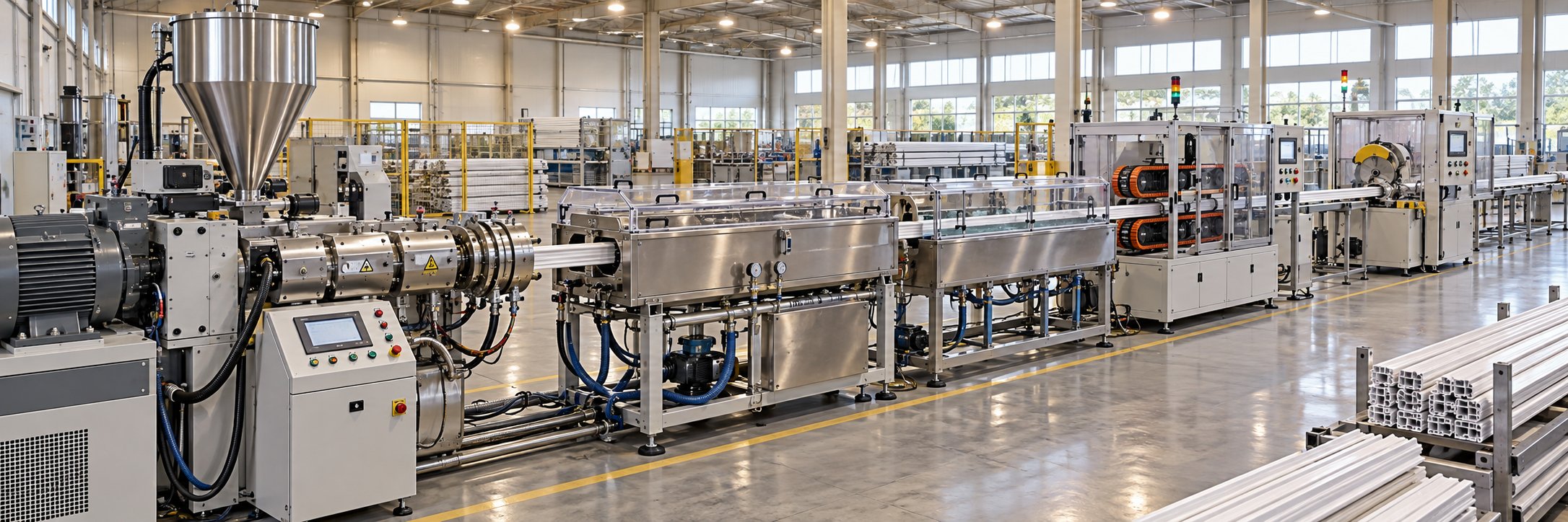
Here is the full pvc profile extrusion process flow, from raw resin bag to cut-to-length product:
- Dry-blend preparation (hot-cold mixing)
- Material feeding into the extruder
- Plasticization and melt homogenization inside the conical twin screw barrel
- Melt delivery through the die adapter and profile die
- Vacuum calibration and initial cooling
- Secondary cooling (spray or immersion tanks)
- Haul-off (belt or caterpillar puller)
- Automatic cutting and stacking
Dry-Blend Preparation and Feeding
The process begins long before plastic enters the barrel. A high-speed hot mixer blends raw PVC resin with heat stabilizers, lubricants, calcium carbonate filler, impact modifiers, and pigments at tip speeds high enough to generate frictional heat. This raises the compound temperature to roughly 110 to 130 degrees C — hot enough to open the resin pores so additives are absorbed into the particle structure rather than simply coating the surface. Rigid PVC-U formulations tend toward the upper end of that range, around 120 to 130 degrees C.
Immediately after discharge, the hot compound drops into a cooling mixer that brings the temperature down below 40 to 45 degrees C. This rapid cooldown is critical — it locks in the additive dispersion achieved during hot mixing and stops premature stabilizer depletion. Skipping or rushing this step leads to agglomerated powder, inconsistent extruder feeding, and batch-to-batch variation that shows up as color shifts or pressure swings at the die.
The cooled dry-blend is then conveyed to the extruder hopper, where the feeding method determines how consistently material enters the screws. You will encounter two main approaches:
- Volumetric feeding — meters material by volume using auger speed. It is simpler and less expensive, but cannot compensate for bulk density variation between batches.
- Gravimetric feeding — continuously measures material by actual weight using load cells and adjusts feed rate in real time. This method actively prevents material surging and is strongly preferred for tight dimensional tolerances.
The choice matters more than it appears. As extrusion line specialists emphasize, precise weight-based feeding is mandatory for achieving strict dimensional stability in the final profile — especially for multi-chamber window and door systems where wall-thickness uniformity is a pass-fail metric.
Plasticization Through Die Shaping
Imagine the dry-blend powder cascading into the wide feed opening of the conical twin screws. Here is what happens inside the barrel, zone by zone:
- Intake at the large end — the wide screw flights grab the low-bulk-density powder and pull it forward. The large diameter provides the torque needed to compact this fluffy material and begin conveying it toward the narrower sections. Air trapped between particles starts escaping through the feed opening and, in some machines, through a vacuum degassing port.
- Progressive compression through the taper — as the screws narrow, channel volume shrinks and the powder compacts further. Barrel heat and inter-particle friction soften the PVC grains. Primary particles begin breaking down and fusing together — a process known as gelation. The counter-rotating screws gently squeeze material between their intermeshing flights, promoting heat transfer from the barrel wall inward without aggressive shear.
- Melt homogenization — in the final screw sections near the discharge tip, the PVC is fully molten. The small screw diameter here means low circumferential speed and minimal additional shear heating. The melt is homogenized into a uniform mass with consistent temperature and viscosity across the entire cross-section.
- Die adapter and profile die — the homogenized melt exits the screw tips and enters the die adapter, which transitions the round barrel outlet into the shape of the profile die. Inside the die, flow channels distribute the melt evenly across every wall, rib, and chamber of the profile geometry. Die design must eliminate all internal dead zones — stagnant PVC will burn and generate black specks or degradation streaks in the finished product.
This entire plasticization sequence — from powder intake to die exit — takes only seconds to tens of seconds, yet the thermal history imprinted during that brief window determines surface quality, mechanical strength, and long-term weathering performance of the profile.
Downstream Line Equipment
The hot, soft extrudate emerging from the die is still shapeless in a practical sense — it needs to be frozen into its final dimensions, pulled at a constant speed, and cut to length. This is where the downstream equipment takes over, and its precision is just as important as the pvc profile extruder itself.
Vacuum calibration tank. The profile enters the calibration unit within centimeters of leaving the die. Inside, vacuum sizing blocks — machined brass or aluminum sleeves matching the profile's outer geometry — apply negative pressure that pulls the soft PVC firmly against their cold surfaces. Chilled water circulating through the tank removes heat rapidly, solidifying the profile into its final shape. If vacuum pressure drops or cooling water temperature rises, the profile warps and pulls away from the calibration sleeve — producing dimensional failures that cannot be corrected downstream.
Spray or immersion cooling tanks. After calibration sets the shape, additional cooling tanks bring the profile temperature down further. Spray cooling uses water nozzles directed at the profile surface, while immersion tanks submerge the profile entirely. The number and length of cooling tanks depend on line speed, profile wall thickness, and the thermal mass of the cross-section. Thick-walled profiles require significantly more cooling length than thin-walled ones running at the same speed.
Haul-off unit. A caterpillar-type haul-off grips the cooled profile between continuous rubber belts and pulls it at a precisely controlled, constant speed. This pulling speed — synchronized with extruder output — determines the final wall thickness and dimensional accuracy of the profile. Too fast, and walls thin out; too slow, and material backs up, causing bulging. For delicate hollow profiles like window frames, the haul-off must grip firmly enough to maintain tension without crushing the chambers.
Automatic cutting system. Finally, a traveling saw or guillotine cutter moves with the profile and cuts it to programmed lengths without stopping the line. Advanced systems use encoder feedback to guarantee cut-length accuracy within fractions of a millimeter. Tipping tables then gently transfer the finished pieces into collection bins for stacking or packaging.
The extruder dictates roughly half the final product quality. The other half depends entirely on how well the downstream calibration, cooling, haul-off, and cutting equipment are matched to the extruder's output rate, the profile's geometry, and each other.
Every component in this chain — from the hot mixer to the saw blade — must operate as an integrated system. A mismatch between extruder output and haul-off speed creates wall-thickness variation. An undersized cooling section forces a line speed reduction that wastes extruder capacity. Unreliable vacuum in the calibration tank produces dimensional rejects even when the melt quality from the extruder is flawless. Recognizing these interdependencies is what transforms a collection of machines into a production line capable of consistent, zero-defect output.
With the full process flow mapped, the next practical question becomes: which extruder size and configuration should you match to your specific profile application and output target?
How to Select the Right Extruder Size for Your Profile Application
You have mapped the process flow, you understand the plasticization mechanics, and you know which barrel temperatures and screw speeds keep rigid PVC in its safe processing window. The question that turns all of that knowledge into a purchasing decision is deceptively simple: which double screw extruder machine size actually fits the profiles you need to produce? Getting the answer wrong means either overpaying for capacity you will never use or — worse — pushing an undersized machine past its limits, accelerating wear and compromising product quality from day one.
Matching Extruder Size to Profile Type and Output
Conical twin screw extruders are identified by their screw diameter pairs — the small discharge-end diameter listed first, followed by the large feed-end diameter. When you see designations like 51/105, 55/110, 65/132, 80/156, or 92/188, those numbers tell you almost everything you need to know about the machine's output range and application fit before reading a single specification sheet.
Smaller machines — the 51/105 and 55/110 sizes — deliver output rates typically in the range of 80 to 200 kg/h. Their compact barrel and lower torque capacity suit lightweight, small-cross-section products: cable trunking, decorative trim, edge banding, skirting boards, and narrow architectural moldings. These profiles have modest cross-sectional areas, limited wall thicknesses, and relatively simple geometries, so the smaller machine's plasticizing capacity is more than adequate.
The 65/132 size occupies the versatile middle ground and is the single most widely deployed conical twin screw extruder in PVC profile production globally. With typical outputs of 200 to 400 kg/h, it handles the majority of window frame, door panel, and multi-chamber profile applications. Its balance of throughput, torque, and footprint makes it the default choice for producers who run a diverse product mix without maintaining multiple dedicated lines.
Larger machines — the 80/156 and 92/188 — push output beyond 400 kg/h and into the 600 to 1,000+ kg/h range. These are purpose-built for high-volume production of large-section profiles such as wide window systems, heavy-duty door frames, structural decking, and wide panel sections where the die's cross-sectional area demands substantial melt volume per minute. The higher motor power and greater barrel volume of these machines also provide the thermal reserve needed to process heavily filled compounds without sacrificing melt uniformity.
Application-Specific Considerations
Screw diameter alone does not complete the pvc profile extruder size selection decision. Profile complexity layers on additional requirements that shift the equation in ways output ratings cannot capture.
Consider a multi-chamber window frame with five or six hollow cavities separated by thin internal ribs. This profile demands exceptional melt homogeneity and pressure stability — even minor viscosity fluctuations cause rib-thickness variation and weakened weld lines where internal walls join the outer shell. The extruder must deliver a perfectly uniform melt at modest throughput, which often means running a 65/132 machine at moderate RPM rather than pushing a smaller 55/110 to its upper output limit. Co-extrusion adds another dimension: when a secondary extruder feeds a cap layer of UV-resistant or colored PVC onto the main profile, the primary extruder's pressure must remain rock-steady despite the additional flow resistance introduced at the co-extrusion die junction.
WPC (wood-plastic composite) profiles introduce entirely different demands. Wood flour loading of 40 to 70% creates a highly abrasive, low-bulk-density compound that fills screw channels poorly and wears flight surfaces aggressively. WPC-specific screw designs feature deeper flights in the feed zone for better material intake and often require bimetallic barrel construction as a baseline — not an upgrade. As industry application guides note, the compression ratio for WPC typically ranges from 2.0:1 to 2.5:1, with processing temperatures held below 180 °C to prevent wood fiber discoloration and volatile release.
Foam-core profiles add yet another variable. Chemical blowing agents decompose within the barrel to create a cellular structure, and the screw must maintain precise pressure control throughout the melt zone. Too much compression collapses the foam cells prematurely; too little allows uncontrolled expansion before the die. Temperature uniformity across every barrel zone becomes especially critical because even small hot spots trigger premature blowing agent decomposition and produce uneven cell structure.
| Profile Application | Typical Extruder Size (Small-End/Large-End mm) | Approximate Output Range (kg/h) | Key Selection Considerations |
|---|---|---|---|
| Cable trunking and conduit | 51/105 to 55/110 | 80 - 200 | Simple geometry; high line speed; moderate filler loading |
| Skirting, trim, and edge banding | 51/105 to 55/110 | 80 - 180 | Small cross-section; surface finish quality critical; may require co-extrusion |
| Window and door frame systems | 65/132 to 80/156 | 200 - 500 | Multi-chamber complexity; weld-line strength; co-extrusion for cap layers; tight dimensional tolerances |
| Structural and wide panel profiles | 80/156 to 92/188 | 400 - 1,000+ | Large cross-sectional area demands high melt volume; heavy CaCO3 loading common |
| WPC decking and cladding | 65/132 to 80/156 | 150 - 400 | Deep-flight feed screw for low-bulk-density wood flour; bimetallic barrel mandatory; lower processing temps |
| Foam-core profiles | 65/132 to 80/156 | 150 - 350 | Precise pressure control for uniform cell structure; tight temperature uniformity across all zones |
| Medical and specialty profiles | 51/105 to 55/110 | 50 - 150 | Clean material handling; possible flexible PVC; lower compression ratio; strict contamination control |
Beyond profile geometry, PVC formulation variables further influence the ideal screw configuration. A rigid compound with 30+ parts CaCO3 per hundred resin generates more abrasive wear than a lightly filled formula, making bimetallic screw and barrel metallurgy essential regardless of machine size. The stabilizer system matters too — calcium-zinc stabilized compounds behave differently under heat than tin or lead-based systems, sometimes requiring adjusted compression ratios or barrel temperature profiles. Even the ratio of internal to external lubricants shifts the fusion characteristics enough to affect optimal screw speed and zone temperatures.
What does all this mean for the twin screw extruder price conversation? Larger machines cost more upfront — not just for the extruder itself, but for the correspondingly larger die, calibration table, cooling tanks, and haul-off needed to match the higher output. Yet running a 55/110 at maximum RPM to meet output targets that a 65/132 handles comfortably at moderate speed accelerates component wear, increases energy consumption per kilogram, and narrows the operating margin for melt quality. The right size is the one that achieves your target throughput at 60 to 80% of maximum capacity — leaving headroom for formulation variation, seasonal demand changes, and the inevitable gradual decline in plasticizing efficiency as screw and barrel components wear over time.
Selecting the correct extruder size sets the stage for consistent output. But even a perfectly matched machine eventually produces defects if operators cannot identify and resolve the surface imperfections, dimensional drift, or structural weaknesses that signal something has shifted in the process — or inside the barrel itself.
Troubleshooting Common PVC Profile Extrusion Defects
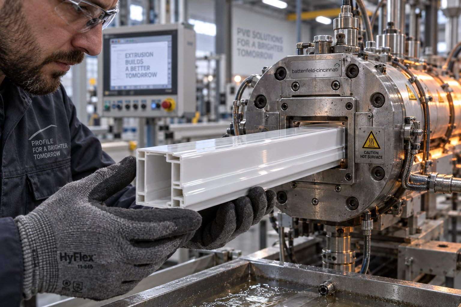
A profile leaves the die looking rough. Another batch shows faint yellow streaks. Wall thickness drifts out of spec on one side of a multi-chamber frame. When defects appear on a PVC extrusion line, the instinct is to start adjusting temperatures and screw speed — sometimes simultaneously. That approach usually makes things worse. Effective troubleshooting follows a simple rule that experienced PVC extruder operators know well: diagnose the pattern before changing the process. As plastics extrusion troubleshooting specialists emphasize, you should determine whether the defect is cross-directional, machine-directional, random, or tied to a specific piece of equipment — then change one variable at a time and document the result.
This pvc extrusion troubleshooting guide organizes the most common profile defects into two categories — surface problems and dimensional or structural problems — and traces each back to its likely extruder-related root cause.
Surface Defects and Their Extruder-Related Causes
Surface quality is the first thing a customer notices and the fastest way to generate rejects. Most surface defects in PVC profiles originate from one of three zones: the plasticizing barrel, the die, or the very first contact point in the calibration tank. Isolating which zone is responsible requires inspecting the extrudate immediately after it exits the die — before calibration and cooling have a chance to mask or introduce additional marks.
Rough or matte surfaces. When a profile emerges with a dull, sandpaper-like texture instead of a smooth gloss, the melt has not achieved sufficient gelation. Typical causes include barrel temperatures set too low, screw speed too high (which shortens residence time below what the compound needs to fully fuse), or worn screw flights that allow material to leak backward over the flight crests instead of being compacted and heated progressively. The fix starts with verifying actual melt temperature at the adapter — not just barrel zone setpoints — and confirming that screw and barrel clearances are still within tolerance.
Shark skin (melt fracture). Fine transverse ridges running across the profile surface indicate that shear stress at the die exit has exceeded the polymer's critical threshold. In a PVC extruder, this typically happens when output is pushed too high for the die gap, when melt temperature is too low (raising viscosity and therefore wall shear), or when die lands are damaged or contaminated. Industry troubleshooting resources note that reducing screw speed, adjusting melt temperature, or improving die geometry are the primary corrective paths — but the key diagnostic step is finding the output threshold where roughness begins, then working backward to identify what changed.
Die lines and streaks. A continuous line running along the machine direction that stays fixed in the same position relative to the die is almost always a die-surface problem — a nick, scratch, carbon buildup, or degraded polymer clinging to the lip or land. These marks cannot be tuned away with temperature or speed changes. The die needs to be cleaned, inspected, and if necessary, re-polished. However, persistent die lines that reappear quickly after cleaning may point to upstream degradation or contamination continuously loading the die surface.
Burn marks and yellowing. Dark specks, brown streaks, or a general yellow discoloration in PVC profiles are unmistakable signs of thermal degradation. Remember, PVC releases HCl gas as it degrades — and that degradation is autocatalytic. Once it starts, it accelerates. The causes trace to excessive melt temperature, dead zones in the die or adapter where material stagnates and cooks, or prolonged residence time from running at very low output on an oversized machine. Worn screw-barrel clearances contribute indirectly here: as screw wear research documents, increasing flight clearance forces operators to raise screw speed to maintain output, which adds shear heat and pushes discharge temperatures higher — sometimes by 10 degrees C or more before the wear is even noticed.
Dimensional and Structural Defects
Surface defects are visible immediately. Dimensional and structural problems can be more insidious — they may pass visual inspection on the line but cause assembly failures, poor weathering performance, or customer complaints weeks later.
Warpage and dimensional instability. A profile that twists, bows, or curls after cutting is suffering from asymmetric internal stresses. On the extruder side, uneven barrel heating across zones — sometimes caused by a single failed heater band that nobody noticed — creates temperature gradients in the melt. One side of the profile cools and shrinks differently than the other, locking in stress that releases as warpage after the profile is cut free from the haul-off tension. Uneven cooling in the calibration tank amplifies the problem, but the root cause often lives inside the barrel.
Inconsistent wall thickness. When wall measurements drift around the profile's cross-section, the culprit is typically uneven melt flow distribution. Screw speed fluctuations — caused by drive instability or feeding interruptions — create machine-direction thickness variation. Cross-directional wall imbalance, where one side of the profile is consistently thicker than the other, usually traces to die centering, but can also result from uneven melt viscosity entering the die. Worn screw and barrel clearances reduce conveying consistency and allow localized backflow that disrupts the uniform pressure front needed to fill every cavity of a complex die evenly.
Poor weld-line strength. In multi-chamber window and door profiles, internal dividers are formed where separate melt streams reconverge inside the die. If the melt arriving at these convergence points is not at uniform temperature and viscosity, the weld line — the seam where the streams rejoin — will be mechanically weak. On the extruder pvc processing side, poor gelation from insufficient barrel temperature or excessive screw speed is the most common contributor. Operators sometimes overlook this because the weld line is invisible on the surface; it only reveals itself during impact testing or when profiles crack along internal ribs during installation.
Here is a structured defect-cause-solution reference you can print and keep near the control panel:
- Rough / matte surface — Cause: Incomplete gelation from low melt temperature, excessive screw speed, or worn screw flights increasing clearance. Solution: Verify actual melt temperature at adapter; check screw flight diameter and barrel bore for wear; reduce screw RPM and increase zone temperatures incrementally.
- Shark skin / melt fracture — Cause: Excessive shear stress at die exit from high output, low melt temperature, or damaged die lands. Solution: Identify the output onset threshold; raise melt temperature within the safe window; inspect and re-polish die lips and lands.
- Die lines / streaks — Cause: Die-lip damage, carbon deposits, degraded polymer buildup, or contamination on the land surface. Solution: Clean and inspect die under approved shutdown procedure; trace recurring deposits to upstream degradation sources.
- Burn marks / yellowing — Cause: Overheating, dead zones in adapter or die, excessive residence time, or worn screws forcing higher RPM that raises shear heat. Solution: Map all stagnation points; check for failed thermocouples or heaters; measure screw-barrel clearance to rule out wear-induced temperature rise.
- Warpage / bowing — Cause: Asymmetric melt temperature from uneven barrel heating, uneven cooling in calibration, or residual stress from inconsistent plasticization. Solution: Verify all barrel heater bands and thermocouples are functional; check cooling water flow symmetry in calibration tank; confirm haul-off alignment.
- Inconsistent wall thickness — Cause: Screw speed fluctuations, feeding interruptions, worn screw-barrel clearance reducing pumping stability, or die misalignment. Solution: Trend melt pressure and motor load for fluctuations; measure screw flight-to-barrel clearance; re-center die tooling.
- Weak weld lines — Cause: Poor gelation delivering non-uniform melt to die convergence points; insufficient melt temperature or pressure at the weld zone. Solution: Increase barrel zone temperatures in the plasticization section; ensure screw-barrel clearance has not degraded plasticizing efficiency; verify die temperature uniformity.
Notice a recurring theme in this list? Worn screw and barrel components appear as a contributing factor in nearly every defect category. That connection is not coincidental. As flight clearance increases beyond specification — whether from abrasive CaCO3 filler, corrosive HCl exposure, or simply accumulated running hours — the screw's ability to generate consistent compression, uniform melt temperature, and stable output pressure deteriorates. Research into screw wear effects shows that a worn screw requires higher RPM to maintain the same output rate, which in turn raises discharge temperature — sometimes by enough to push PVC past its degradation threshold. At that point, the operator is chasing symptoms (yellowing, rough surfaces, pressure swings) while the actual root cause sits quietly inside the barrel, invisible until someone pulls the screws and measures the flights.
Before adjusting temperatures, speeds, or die settings, always ask one question first: when was the last time screw flight diameter and barrel bore were measured? Many PVC profile defects blamed on process parameters are actually wear problems disguised as process problems.
Recognizing that wear is often the hidden variable behind persistent quality issues leads directly to the most important operational discipline on any extrusion line — a structured, proactive approach to monitoring and maintaining the components at the heart of the plasticizing system.
Maintenance Best Practices for Long Extruder Service Life
Defects get the attention, but wear gets the blame — eventually. The troubleshooting patterns explored above repeatedly point to screw and barrel condition as the hidden variable behind persistent quality drift. Yet on many production floors, conical twin screw extruder maintenance remains reactive: components are replaced only after output drops noticeably or a catastrophic failure forces an emergency shutdown. That approach is expensive. A structured preventive program catches degradation early, extends component life, and keeps your plastic twin screw extruder running at peak plasticizing efficiency.
Screw and Barrel Wear Monitoring
How do you know when your screws and barrel need attention? You measure. Specifically, you measure screw flight outer diameter and barrel bore inner diameter at multiple points along the length — feed zone, compression zone, and metering zone — using precision micrometers and bore gauges. Comparing these readings against the original nominal dimensions reveals the actual flight clearance, which is the single most important wear indicator on any twin screw plastic extruder.
When new, the flight clearance on a typical extruder is roughly the nominal screw diameter divided by 1,000 per side. As extrusion wear research documents, clearance beyond this baseline is due to wear — and the performance consequences escalate quickly. A general industry guideline suggests investigating replacement when flight clearance reaches two to four times the original value, depending on the criticality of the application. For PVC window profiles with tight dimensional tolerances, the lower end of that range applies.
You do not always need calipers to suspect a problem. Watch for these performance symptoms that signal excessive wear:
- Reduced specific output — the ratio of throughput (kg/h) to screw speed (RPM) drops because material leaks backward over widened flight clearances instead of being conveyed forward.
- Higher discharge temperatures — operators compensate for lost output by increasing screw speed, which adds shear heat. The same research shows discharge temperature can climb 10 degrees C or more before the root cause is identified.
- Increased energy consumption — more motor power is consumed to maintain the same production rate, because the screws are working harder to overcome backflow losses.
- Inconsistent melt quality — pressure fluctuations at the die adapter, visible surface defects, and batch-to-batch variation that was not present when the screws were new.
CaCO3-filled rigid PVC compounds accelerate this wear timeline significantly. Calcium carbonate particles, while only mildly abrasive individually, act like fine sandpaper grinding against flight crests and barrel bore surfaces over thousands of running hours. Compounds loaded at 20 to 40 parts per hundred resin wear flight hard-facing faster than lightly filled formulations — and the corrosive HCl released during normal PVC processing attacks any exposed base metal once the protective surface treatment erodes. This dual abrasive-corrosive mechanism is why PVC profile producers running heavily filled compounds should measure screw and barrel dimensions every 500 to 1,000 operating hours rather than waiting for visible symptoms.
One practical tip: keep a spare screw set in storage. When measurements confirm the current screws have reached their wear limit, you can swap immediately — minimizing downtime to hours instead of the days or weeks needed to order and receive replacements. A worn screw can be refurbished with new hard-facing, but industry experience cautions against refurbishing the same screw more than three times, because repeated welding degrades the base metal and increases delamination risk. For the barrel, an iron-based bimetallic liner typically outlasts the screws by roughly three service cycles — but only if the barrel bore is measured at every screw change to confirm it is still within tolerance.
Cleaning Procedures and Preventive Maintenance Schedules
Wear is gradual. Thermal damage from improper startups and shutdowns is immediate. How you start and stop the machine — and how you handle material changeovers — directly determines how long your screw surfaces and barrel lining last.
Shutdown procedure. The goal is to purge the current PVC compound at operating temperature with a thermally stable purge material, then reduce barrel temperatures to a safe holding level before stopping the screws. Extrusion equipment specialists recommend reducing screw speed at the end of a production run while introducing a purge compound blended with antioxidant — this displaces the heat-sensitive PVC and fills the barrel with a material that will not degrade during cooldown. Never shut the screws down with PVC compound sitting at full operating temperature. Stagnant PVC will degrade, carbonize, and bond to metal surfaces, creating contamination sources that persist through subsequent production runs.
Startup procedure. Bring the barrel to a temperature lower than normal operating temperature and allow adequate heat-soak time to ensure the polymer remaining inside is fully molten before rotating the screws. Starting cold — or starting before the material has softened — creates enormous torque loads on cold, brittle polymer, risking screw damage and motor overload. The heat-soak duration depends on barrel size and heating system capacity; larger machines require longer soaks.
Color and material changeovers. Purge thoroughly between compounds, especially when switching from dark to light colors. Use an approved PVC-compatible purge compound or the next production compound run at elevated temperatures to scrub residual material from screw channels, barrel walls, and die flow paths. Verify the purge is complete by inspecting extrudate color and clarity before resuming production.
Pulling all of these practices together into a scheduled routine prevents the small oversights that compound into major failures. Here is a conical twin screw extruder maintenance checklist organized by interval:
- Daily
- Check all barrel zone temperatures against setpoints; investigate any zone that fails to reach or hold target
- Monitor motor amperage and melt pressure for deviations from baseline
- Inspect the hopper and feed throat for material bridging or contamination
- Verify cooling water flow and temperature to barrel cooling circuits
- Listen for unusual gearbox or bearing noise
- Weekly
- Check gearbox oil level and inspect for leaks at seals
- Inspect heater band connections and tighten any loose terminal blocks
- Verify thermocouple readings against a handheld probe to catch sensor drift
- Inspect drive belts or couplings for wear, tension, and alignment
- Clean feed hopper and magnet screens
- Monthly
- Test all safety interlocks and emergency stop functions
- Inspect barrel heater bands for cracking, discoloration, or loss of contact with the barrel surface
- Check cooling water strainers and filters for blockages
- Record and trend motor bearing temperatures
- Inspect barrel vent ports (if present) for buildup or blockage
- Annually (or every 4,000-8,000 operating hours)
- Pull screws and measure flight outer diameter at multiple positions along the length
- Measure barrel bore inner diameter at corresponding positions
- Calculate actual flight clearance and compare against new-component baseline
- Inspect screw surfaces for scoring, corrosion pitting, or hard-facing delamination
- Perform gearbox oil change and inspect gear teeth and thrust bearings
- Check barrel alignment, especially on long machines or if the foundation has shifted
- Calibrate all temperature controllers, pressure transducers, and motor load monitors
Sticking to this schedule transforms maintenance from a cost center into a quality insurance policy. Proactive screw and barrel replacement — planned during scheduled downtime — avoids the cascading costs of unplanned stops: emergency parts at premium prices, rush shipping, lost production hours, and the scrap generated during the process restabilization that follows every emergency repair. The discipline is straightforward, even if the commitment is not always easy: measure regularly, document trends, and replace components before they force the decision for you.

Industry Trends and Next Steps for PVC Profile Producers
Maintenance discipline keeps today's equipment performing. But the machines, materials, and market pressures shaping PVC profile extrusion are evolving rapidly — and producers who track these shifts early gain a real competitive edge over those who react after the industry has already moved.
Industry Trends Shaping Conical Twin Screw PVC Extrusion
The lead-free stabilizer transition is accelerating — and it changes what happens inside your barrel. Europe completed its lead-stabilizer phase-out years ago, but the ripple effects are still spreading. Staged bans across China, India, and Latin America are driving rapid adoption of calcium-zinc (Ca/Zn) and organic-based stabilizer (OBS) systems. These newer chemistries are not simple drop-in replacements. As Plastics Engineering reports, hybrid CaZn-LDH and OBS stabilizers reduce melt pressure by 10 to 15 percent while maintaining uniform gelation — but they also shift fusion behavior, lubrication balance, and thermal stability windows in ways that demand recalibrated screw designs and updated process recipes. The global lead-free PVC stabilizer market reached nearly USD 3.2 billion in 2023, with the total PVC stabilizers market projected to grow from USD 4.6 billion in 2024 to almost USD 6.9 billion by 2033. That growth is not abstract — it means your next compound reformulation will almost certainly involve a lead-free stabilizer system if it does not already.
What does this mean for screw and barrel configuration? Ca/Zn stabilized compounds can exhibit different rheological behavior than legacy lead-based formulations: altered melt viscosity curves, different plate-out characteristics on die surfaces, and modified fusion kinetics. Some producers find that compression ratios optimized for lead-stabilized compounds need adjustment — slightly lower compression or modified flight geometry — to accommodate the broader fusion range that modern hybrid stabilizers provide. Screw designs that were dialed in for one stabilizer chemistry may produce inconsistent gelation or surface defects when the formulation shifts underneath them.
High-speed extrusion and energy efficiency are converging. The latest generation of conical twin screw extruders features improved drive systems — high-torque servo motors, optimized gearbox designs, and intelligent power management — that deliver more output per kilowatt consumed. Industry reporting on twin screw extruder advances highlights that modern machines integrate advanced sensors for real-time monitoring of screw speed, temperature, and pressure, alongside improved heat exchange systems and enhanced barrel insulation to conserve energy. Machine learning algorithms are beginning to optimize power usage based on real-time processing conditions — a shift that turns the extruder from a manually tuned machine into a self-adjusting system. For producers evaluating upgrades, an energy-efficient plastic profile extruder is no longer a premium option; it is becoming the baseline expectation as electricity costs rise and sustainability reporting requirements tighten.
WPC and foam-core profile demand continues to grow. Wood-plastic composite decking, cladding, and fencing markets are expanding globally, pulling conical twin screw extruders into applications that place very different demands on screw design. High wood-flour loading (40 to 70 percent) means extreme abrasion, low bulk density feeding challenges, and strict temperature ceilings to prevent fiber discoloration. Foam-core PVC profiles — lighter, more material-efficient, and increasingly specified for interior construction — require screw geometries that maintain precise pressure control for uniform cell structure. Both trends push twin-screw extruder manufacturers toward more application-specific screw and barrel engineering rather than one-size-fits-all solutions.
Taking the Next Step Toward Optimized Production
This guide has covered a lot of ground — from the polymer science that makes conical geometry the right answer for PVC, through screw design variables and processing parameter relationships, across the complete process flow, and into the troubleshooting and maintenance practices that sustain zero-defect performance over time. Here are the core takeaways worth anchoring:
- Conical twin screw geometry is purpose-built for PVC's thermal sensitivity — its tapering design delivers high feed-zone torque and low discharge-zone shear in a single compact package.
- Processing parameter optimization is always profile-specific. No borrowed recipe replaces systematic trials matched to your exact combination of die, compound, and downstream equipment.
- Most persistent quality defects trace back not to temperature or speed settings, but to worn screw and barrel components where excessive clearance has silently degraded plasticizing efficiency.
- Proactive maintenance — scheduled measurement, documented trends, and planned replacement — costs a fraction of the emergency repairs, scrap, and lost production hours it prevents.
An extruder's performance ultimately depends on the precision and condition of the screw and barrel at its heart. Every other optimization — temperature tuning, speed balancing, die adjustment — builds on that foundation.
Whether you are commissioning a new line, reformulating for lead-free stabilizers, expanding into WPC or foam-core profiles, or simply noticing that your current output consistency is not what it used to be, the screw and barrel are the starting point for every improvement. Manufacturers seeking custom-engineered or replacement conical twin screw barrels for PVC pipe, profile, board, foam board, or WPC applications can explore NANHAIYA's dedicated conical twin screw barrel solutions, which are designed for stable plasticizing performance across a wide range of PVC formulations and backed by production support expertise that helps match metallurgy and geometry to your specific application demands.
The technology inside these machines will keep evolving — smarter controls, more efficient drives, and formulations that would have been unrecognizable a decade ago. What will not change is the fundamental principle that precise, well-maintained screw and barrel components are the non-negotiable foundation of every quality PVC profile that comes off the line.
Frequently Asked Questions About Conical Twin Screw Extruders for PVC Profiles
1. Why is a conical twin screw extruder preferred over a parallel twin screw extruder for PVC profiles?
PVC degrades at temperatures very close to its processing range, so it requires gentle, low-shear plasticization. A conical twin screw extruder addresses this with tapered screws that provide high torque at the wide feed end for efficient powder intake and progressively lower circumferential speed toward the narrow discharge end, reducing shear heating exactly where the molten PVC is most vulnerable. This built-in compression also eliminates the need for complex screw-element configurations. Parallel designs can work for PVC, but they demand more sophisticated screw engineering to manage shear, making conical machines the standard choice for profile extrusion where compact footprint and thermal control are priorities.
2. What screw diameter size should I choose for my PVC profile extrusion line?
The right size depends on your target output rate and profile complexity. Small machines like 51/105 or 55/110 suit cable trunking, trim, and edge banding at 80-200 kg/h. The 65/132 is the most versatile and widely used size, handling window frames and door panels at 200-400 kg/h. Larger 80/156 and 92/188 machines serve high-volume structural profiles and wide panels at 400-1,000+ kg/h. A practical rule is to select a machine that meets your throughput target at 60-80% of its maximum capacity, leaving headroom for formulation variation and gradual component wear over time.
3. How do I know when the screw and barrel on my conical twin screw extruder need replacement?
Measure screw flight outer diameter and barrel bore inner diameter at multiple points along their length using precision gauges, then compare against original specifications. Replacement is generally warranted when flight clearance reaches two to four times the original value. Performance symptoms that signal excessive wear include reduced specific output (kg/h per RPM), rising discharge temperatures despite unchanged settings, increased motor amperage, and inconsistent melt quality with pressure fluctuations. For CaCO3-filled rigid PVC compounds, measurements should be taken every 500-1,000 operating hours. Suppliers like NANHAIYA (nhyscrews.com) offer custom replacement conical twin screw barrels engineered with bimetallic linings and hard-facing to extend service intervals in abrasive PVC applications.
4. What causes yellowing or burn marks in extruded PVC profiles?
泛黄和烧痕是PVC热降解的直接迹象,这是由于脱氯化氢反应造成的,该反应会从聚合物链中释放出氯化氢气体。常见的挤出机相关原因包括熔体温度超过185-200℃的安全范围、模头适配器中物料停滞和过热的死区,以及在过大尺寸机器上低产量运行导致物料停留时间过长。一个经常被忽视的原因是螺杆螺纹磨损:随着间隙增大,操作人员会提高螺杆转速以弥补产量损失,这会增加剪切热,并可能导致出料温度比目标温度高出10℃或更多。在调整工艺参数之前,务必测量螺杆与料筒之间的间隙。
5. 改用无铅PVC稳定剂对锥形双螺杆挤出机的设置有何影响?
与传统的铅基配方相比,钙锌和有机基稳定剂体系会改变PVC熔体的流变性、熔融动力学和润滑平衡。生产商在更换稳定剂体系时,通常会发现需要重新校准现有的压缩比和料筒温度曲线。钙锌稳定剂化合物可能表现出不同的熔体粘度曲线和在模头表面的流延行为。在某些情况下,略微降低压缩比或改进螺杆几何形状可以改善凝胶均匀性。当稳定剂化学成分发生变化时,应通过系统试验重新验证为铅基稳定剂化合物建立的工艺配方库,并相应地调整区域温度、螺杆转速和熔体压力目标值。
Written by
Nanhaiya Technical Team
Zhoushan Nanhaiya Plastic Machinery Co., Ltd.
The Nanhaiya technical team supports screw and barrel manufacturing projects through application review, technical communication, custom manufacturing coordination, and production and quality control.
Discuss Your Application
Related Articles
More insights on screw barrel technology and plastics processing.

What Nobody Tells You About Screw Barrel For Plastic Machine Design
Oct 10, 2026
Learn how screw barrel for plastic machine design affects melt quality, throughput, and wear life. Covers geometry, resin matching, troubleshooting, and sourcing.
Read Article
Single Screw Extruder for Sheet: Stop Guessing, Start Specifying
Oct 9, 2026
Learn how to specify a single screw extruder for sheet production. Covers screw geometry, resin-specific processing, troubleshooting, and maintenance best practices.
Read Article
PE Pipe Extruder Machine: What Datasheets Won't Tell You
Oct 9, 2026
Learn how a PE pipe extruder machine works, key specs explained, material grade selection, maintenance tips, and buyer guidance beyond the datasheet.
Read ArticleLooking for something else?
Search by material, symptom or product and jump straight to the relevant page.
These are navigation suggestions based on keyword matching — not a quotation, not a delivery commitment, and not a substitute for engineering review. Final specification is confirmed by our engineers against your drawings and processed material.
Need help with screw barrel selection?
Share your machine model, processed material and application. Our team can help with pricing and technical support.