

What a WPC Profile Extrusion Machine Is and Why It Matters
Imagine taking sawdust and recycled plastic, feeding them into one end of a production line, and pulling out a perfectly shaped deck board or window frame at the other end. That is exactly what a WPC profile extrusion machine does — and the engineering required to make it happen is far more specialized than most buyers realize.
What Is a WPC Profile Extrusion Machine
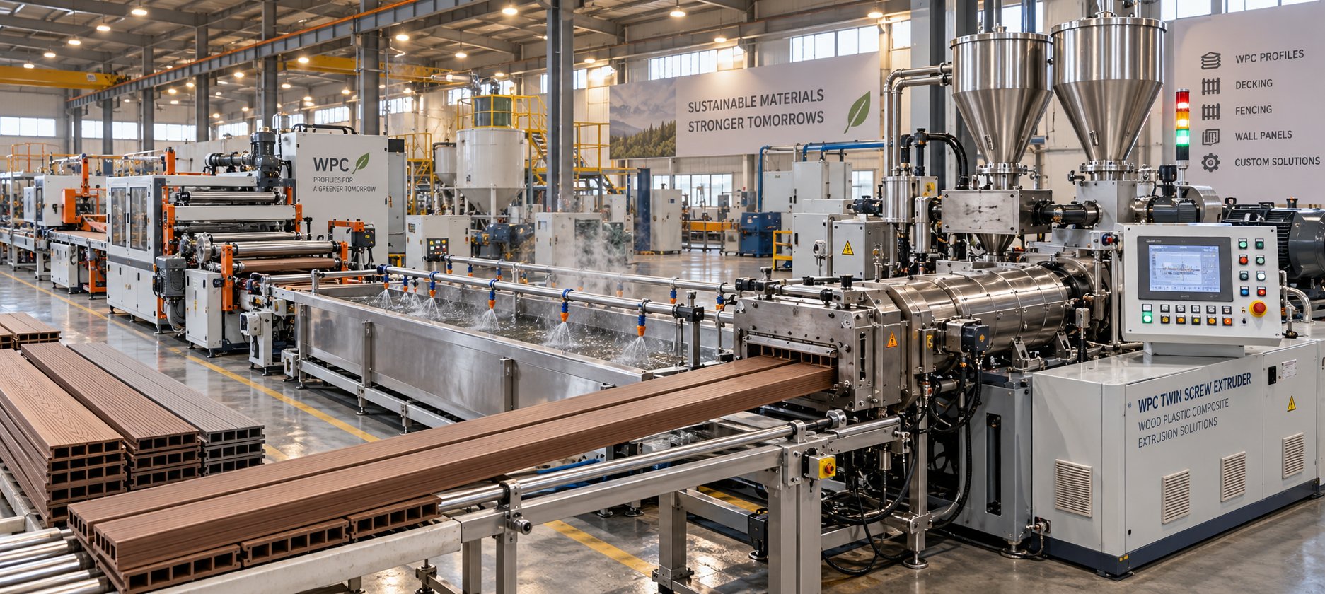
A WPC profile extrusion machine is a purpose-built production line that blends wood flour with thermoplastic polymers — typically PVC, PE, or PP — and continuously shapes the molten composite through a die to produce structural and decorative profiles such as decking boards, wall cladding, fencing rails, and window frames.
Unlike a general-purpose plastics extruder, every component in a WPC profile extrusion machine line is engineered to handle the unique behavior of a wood-polymer blend. From the high-torque drive system and vented barrel to the precision calibration tables downstream, the entire line reflects a single reality: wood flour is not just another filler. It is an organic, moisture-sensitive, thermally fragile material that fundamentally changes how the extrusion process must be controlled.
The market behind these machines is surging. The global wood-plastic composite market was valued at USD 10.04 billion in 2025 and is projected to reach USD 29.94 billion by 2034 at a CAGR of 12.91%. Construction — especially decking, fencing, and cladding — drives the bulk of that demand. More than 100 companies worldwide now manufacture WPC products, and the number keeps climbing as builders and consumers seek materials that resist moisture, insects, and rotting without the maintenance headaches of natural wood.
Why WPC Profiles Demand Specialized Machinery
So why can't you simply run a WPC blend through a standard plastics extrusion line? Three core challenges stand in the way:
- Thermal sensitivity of wood flour. Wood fibers begin to degrade at approximately 200 °C, which is well within the normal processing range for many thermoplastics. This narrow thermal window demands tighter temperature control across every barrel zone than a conventional plastics line is designed to deliver.
- High torque requirements. Adding 30-70% wood flour to a polymer dramatically increases melt viscosity. The extruder's motor and gearbox must deliver substantially higher torque — often at lower screw speeds — to convey and plasticize this heavy, abrasive blend without overheating it.
- Moisture and volatile management. Wood flour naturally holds moisture. During processing, that moisture turns to steam, causing bubbles, rough surfaces, and internal voids unless the barrel includes dedicated vacuum venting ports for degassing — a feature rarely found on standard plastic extruders.
Each of these challenges shapes the design of a WPC profiles line extrusion machine in ways that will become clear as you move through this guide. The sections ahead break down every stage — from raw material preparation and extruder configuration to downstream equipment and real-world troubleshooting — so you can evaluate machinery with confidence rather than relying on brochure specs alone.
How WPC Extrusion Differs from Standard Plastic Extrusion
On the surface, a PVC WPC profile extrusion machine looks a lot like any other profile extrusion line — barrel, screw, die, cooling table, haul-off. So why can't you simply swap the raw material and press "start"? The answer lies in three engineering realities that separate WPC processing from conventional thermoplastic extrusion. Understanding these differences is the fastest way to grasp why every component on the line needs to be purpose-matched to the composite material running through it.
Thermal Sensitivity and Wood Flour Behavior
Standard PVC profile extrusion routinely operates between 160 °C and 200 °C, while PE and PP processing can push well above 220 °C without concern. Wood flour changes that equation dramatically. Cellulose and lignin — the primary structural components of wood fiber — begin to thermally degrade at roughly 200 °C. Push the temperature higher and you'll see dark specks, off-gassing, and a noticeable burnt odor that signals molecular breakdown.
This creates an unusually narrow processing window. On a PE WPC profile extrusion machine, for instance, the polymer itself melts comfortably around 130-160 °C, but you still need enough thermal energy to fully fuse the wood-polymer blend into a homogeneous melt. Operators must walk a tightrope: high enough to plasticize properly, low enough to avoid charring the wood component. That demands tighter temperature control across every barrel zone, often with individually regulated heater bands and forced-air cooling jackets that can react quickly to even small temperature deviations.
Higher Torque and Drive Requirements
Picture stirring a bowl of thick cookie dough versus a cup of warm honey. That contrast captures, in a rough way, what happens to melt viscosity when you add 40-70% wood flour to a polymer matrix. The wood particles do not melt — they remain solid inclusions suspended in the polymer, resisting flow at every point along the screw channel.
This elevated viscosity means the extruder motor and gearbox must deliver significantly higher torque, typically at lower screw speeds, than an equivalent-output plastics-only line. Running the screw faster to compensate is not an option because increased speed generates additional shear heat — exactly the kind of uncontrolled heat that pushes wood flour past its degradation threshold. Robust gearboxes with higher torque ratings and motors sized for sustained low-speed, high-load operation are therefore standard requirements on any WPC floor profile extrusion machine built for reliable production.
Moisture Management and Degassing Needs
Even after pre-drying, wood flour can retain residual moisture in the range of 1-3%. Sounds trivial? Inside a heated barrel at processing temperatures, that small percentage of water rapidly converts to steam. Without an effective escape route, the steam creates bubbles, internal voids, and rough surface textures that ruin profile quality.
This is where vacuum venting ports become essential. Positioned along the barrel at strategic points, these ports apply negative pressure to draw steam and other volatiles out of the melt before it reaches the die. A standard plastics extruder typically lacks these ports altogether, or may have a single atmospheric vent that cannot match the degassing intensity WPC requires. High-efficiency vacuum venting — often operating at pressures between 10-50 mbar — is critical to prevent foaming, maintain consistent cell structure in foamed-core profiles, and deliver smooth surface finishes.
| Parameter | Standard PVC Profile Extrusion | WPC Profile Extrusion |
|---|---|---|
| Processing Temperature Window | 160-200 °C (relatively wide) | 150-190 °C (narrow; must stay below ~200 °C to prevent wood degradation) |
| Torque Demand | Moderate — polymer melts flow easily | High — solid wood particles increase melt viscosity by 30-60% |
| Venting Requirements | Minimal or single atmospheric vent | One or more vacuum venting ports essential for moisture and volatile removal |
| Screw Wear Rate | Low to moderate | High — wood flour and mineral fillers are abrasive, accelerating screw and barrel erosion |
| Screw Speed Range | Moderate to high | Lower range preferred to limit shear heat generation |
The table above makes one thing clear: WPC extrusion is not harder in a single dimension — it is more demanding across every critical parameter simultaneously. Temperature control, mechanical drive, and degassing all require upgrades compared to a standard plastics setup. These overlapping constraints are precisely why the machine configurations used for WPC profile production — conical twin screw, parallel twin screw, and single screw — each bring distinct trade-offs to the table.
Conical vs Parallel Twin Screw vs Single Screw Extruders Compared
Every WPC profile extrusion machine manufacturer faces the same fundamental design question before anything else gets engineered: which extruder type should sit at the heart of the line? The answer shapes everything downstream — motor sizing, die design, output capacity, even the type of raw material blend you can feed directly. Yet most product pages simply state "twin-screw extruder" and leave it at that, as if all twin-screw machines are interchangeable. They are not.
Three distinct extruder configurations dominate WPC profile production, and each one brings a very different set of strengths and compromises to the factory floor. Choosing the wrong type can mean sluggish output, inconsistent melt quality, or unnecessary capital cost. Here is what separates them — and when each one makes the most sense.
Conical Twin Screw Extruders for WPC
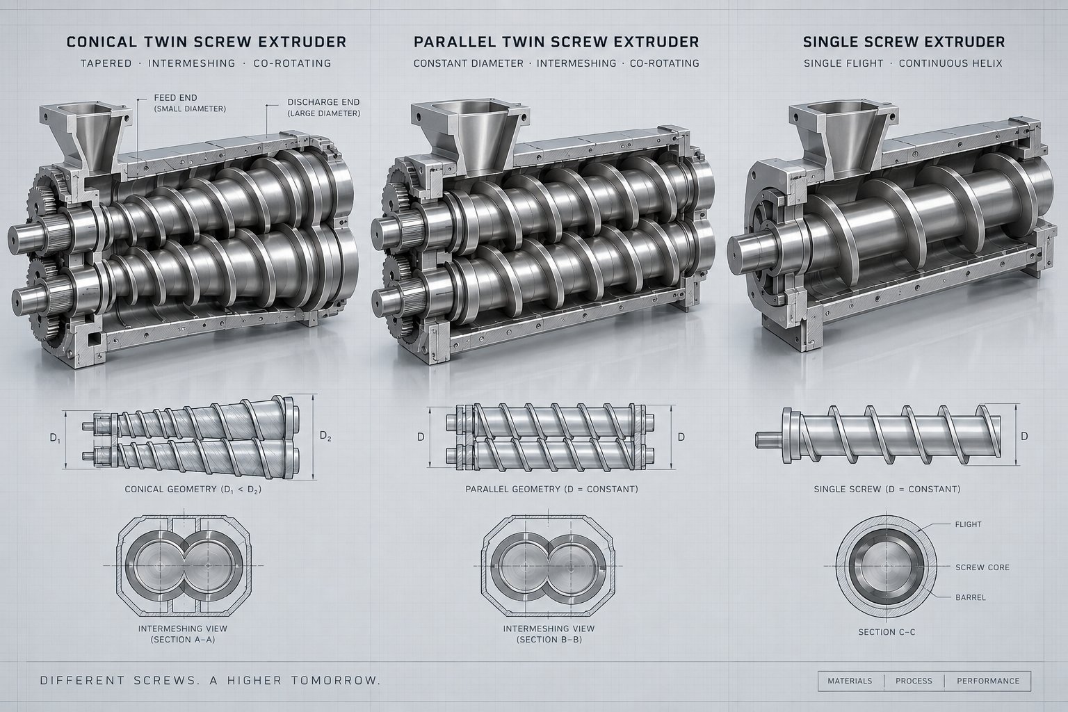
If you visit a factory producing PVC-based WPC decking, cladding, or window profiles, you'll almost certainly find a conical twin-screw extruder running the line. There is a good reason for that dominance. The conical design uses two tapered, counter-rotating screws — wide at the feed end, narrow at the die end — that naturally compress the material as it moves forward. This geometry delivers exceptionally high torque at low screw speeds, typically in the 30-150 rpm range, which is exactly the operating sweet spot for heat-sensitive WPC formulations.
Why does that matter so much? Recall the processing challenges from the previous section: wood flour degrades above roughly 200 °C, and high screw speeds generate shear heat that can push the blend past that threshold. A conical twin screw keeps shear heat in check by producing its power through mechanical compression rather than rotational speed. The large feed opening also handles the low bulk density of wood-flour-and-PVC dry-blend powder far better than a narrow, constant-diameter intake would.
Additional advantages include a compact machine footprint — the tapering barrel is inherently shorter than a parallel equivalent for similar output — and strong de-aeration during the compression phase. For any WPC profile extrusion machine manufacturer in China or elsewhere building PVC-WPC lines, the conical twin screw remains the default starting point.
Parallel Twin Screw Extruders for WPC
Parallel twin-screw extruders take a different approach. Two screws of constant diameter run side by side, most often in a co-rotating configuration, and they excel at something the conical design handles only adequately: intensive distributive mixing. When the polymer base is PE or PP rather than PVC, and the formulation includes high filler loads or multiple additives requiring thorough dispersion, a parallel twin screw is often the better tool.
Co-rotating parallel screws create an infinity-shaped (∞) flow pattern that continuously exchanges material between the two screw channels. This intense mixing action disperses wood flour, coupling agents, UV stabilizers, and pigments more uniformly than counter-rotating conical screws typically achieve. Parallel machines also run at much higher speeds — commonly 400-600 rpm for compounding applications — and offer modular screw configurations. Operators can rearrange kneading blocks, conveying elements, and venting sections along the shaft to fine-tune the process for specific formulations.
The trade-off? Parallel twin screws generate more shear heat at those elevated speeds, which requires careful thermal management to keep wood flour below its degradation ceiling. They also tend to have a higher capital cost and a larger physical footprint than conical machines of similar output. Many WPC producers use parallel twin screws primarily for the compounding and pelletizing step — creating uniform WPC pellets — and then feed those pellets into a separate profile extrusion line. This two-step workflow leverages the parallel machine's mixing strengths while letting a conical or single-screw extruder handle the final shaping at gentler conditions.
Single Screw Extruders and Their Limitations
Sounds simpler and cheaper — so why not just use a single screw? You can, but only under specific conditions. A single-screw extruder has one rotating screw inside a smooth barrel, relying on friction between the material and barrel wall to convey the melt forward. This works well enough for pre-compounded WPC pellets where the wood flour and polymer have already been intimately mixed and dried during a prior compounding step.
The limitations become obvious when you try to feed raw powder blends directly. A single screw lacks the intermeshing action that twin screws use to positively convey and knead material. Bulky, low-density wood-flour blends tend to bridge over the feed throat, causing inconsistent intake. Mixing efficiency is significantly lower, so poorly dispersed wood particles can create weak spots and surface defects in the finished profile. Venting capability is also restricted — most single-screw barrels accommodate one vent at best, which is rarely sufficient for the moisture and volatile load that raw WPC blends carry.
In practice, single-screw machines fill a specific niche: downstream profile extrusion of pre-compounded pellets in a two-step production setup, or small-batch specialty runs where investment in a twin-screw line isn't justified. For direct, one-step WPC extrusion from powder, twin-screw configurations — whether conical or parallel — remain the industry standard.
| Feature | Conical Twin Screw | Parallel Twin Screw | Single Screw |
|---|---|---|---|
| Torque Capability | High torque at low speed (30-150 rpm); ideal for viscous WPC melts | Moderate to high torque at high speed (400-600+ rpm) | Moderate; limited by single-screw friction-driven conveying |
| Ideal Polymer Base | PVC-based WPC (dominant application) | PE- and PP-based WPC; also used for compounding PVC-WPC pellets | Any polymer — but only with pre-compounded WPC pellets |
| Output Range | 100-900 kg/h depending on model size (e.g., 45/90 to 92/188) | 200-2,000+ kg/h; scalable with screw diameter and speed | 50-500 kg/h for typical WPC profile applications |
| Mixing Efficiency | Good — counter-rotating intermeshing provides solid blending | Excellent — co-rotating ∞-pattern delivers intensive distributive and dispersive mixing | Limited — relies on barrel friction; poor for raw powder blends |
| Degassing Ability | Good — compression zone and venting ports handle moisture effectively | Very good — modular barrel allows multiple vacuum vent positions | Poor — typically one vent port; insufficient for raw WPC blends |
| Typical Application | Direct extrusion of PVC-WPC profiles (decking, cladding, frames) | WPC compounding and pelletizing; PE/PP-WPC profile extrusion | Profile extrusion from pre-compounded WPC pellets only |
The comparison reveals a clear hierarchy. For most WPC profile producers — especially those running PVC-based formulations or seeking a compact, cost-effective china WPC profile extrusion machine — the conical twin screw is the proven workhorse. Parallel twin screws earn their place when intensive mixing, high filler dispersion, or PE/PP-based compounding is the priority. Single screws serve a supporting role, best suited as the second machine in a two-step line rather than a standalone solution.
Selecting the right extruder type, however, is only the starting point. Even the most capable twin-screw machine will struggle if the raw materials entering the feed throat aren't properly prepared — and the pre-processing steps that ensure a smooth, consistent feed are among the most overlooked stages in WPC production.
Pre-Processing Steps That Determine Extrusion Success
Here is a pattern you'll notice at WPC profile extrusion machine factories around the world: the lines producing the most consistent profiles aren't necessarily running the most expensive extruders. What sets them apart is what happens before the material ever reaches the feed throat. Pre-processing — drying, blending, compounding, and metering — is the unglamorous foundation that either supports flawless production or quietly sabotages it. Skip or shortchange any of these steps, and even a perfectly tuned twin-screw extruder will fight upstream problems all shift long.
Wood Flour Drying and Moisture Control
Raw wood flour straight from the supplier typically carries a moisture content of 5-8%, and in humid climates it can climb even higher. Research on beech-wood flour, for example, measured a starting moisture content of 5.56% at ambient conditions. That might sound harmless until you remember what happens inside a heated barrel: water turns to steam, steam creates bubbles, and bubbles produce surface blisters, internal voids, and inconsistent melt density. Moisture is the single most common root cause of WPC extrusion defects — and the single easiest to eliminate.
Target moisture levels depend on the formulation, but most WPC profile extrusion machine factory guidelines call for wood flour dried to below 1-3% before it enters the blending stage. PVC-based formulations tend to require the lower end of that range because PVC is especially sensitive to steam-driven porosity, while PE and PP blends can tolerate slightly higher residual moisture when paired with aggressive barrel degassing.
How do you get there? Two types of drying equipment dominate WPC pre-processing:
- Hot-air rotary dryers (drum dryers). These tumble the wood flour through a heated airstream, evaporating moisture rapidly and continuously. They handle large throughput volumes and are the standard choice for dedicated WPC factories processing several tons of wood flour per day.
- Flash dryers (pneumatic dryers). These suspend fine wood particles in a high-velocity hot-air column, achieving very fast drying times — sometimes under a minute — due to the enormous surface area exposed. They work well for fine-mesh flour but require careful temperature control to avoid thermal degradation before the material even reaches the extruder.
Regardless of dryer type, the dried flour should be stored in sealed bins or silos with minimal air exposure. Wood flour is hygroscopic — it reabsorbs ambient moisture quickly — so a two-hour delay between drying and feeding can undo much of the effort.
Compounding Then Extruding vs Direct One-Step Extrusion
Once the wood flour is dry, producers face a strategic fork in the road: should the raw ingredients be compounded into uniform pellets first and then fed into a profile extrusion line (two-step), or should everything be blended and extruded in a single pass (one-step)?
The two-step approach runs the dried wood flour, polymer resin, coupling agents, UV stabilizers, and colorants through a compounding extruder — usually a co-rotating parallel twin screw — to produce homogeneous WPC pellets. Those pellets are then stored, transported if needed, and fed into a separate profile extrusion machine (often a conical twin screw or single screw) for final shaping. The advantage? Pellets are uniform in composition, density, and moisture content, which means the profile extruder receives an extremely consistent feed. Quality control is easier to isolate — if a profile defect appears, you know the issue lies in the extrusion step rather than the compounding step. Many large-scale WPC profile extrusion machine factories in China and Europe favor this route precisely because it simplifies process troubleshooting and supports high-volume, multi-line operations where a central compounding facility supplies several downstream profile lines.
The one-step approach skips the separate compounding stage entirely. Raw powder blends — wood flour, polymer powder, and additives — are dosed directly into the feed throat of the profile extruder, which must handle mixing, degassing, and profile shaping all within a single barrel. This reduces total equipment cost (one machine instead of two), cuts energy consumption, and eliminates the need to re-melt pellets. The trade-off is that the extruder bears the full burden of achieving homogeneous mixing while simultaneously controlling temperature and maintaining profile dimensions. Any feeding irregularity — a clump of undispersed wood flour, a pocket of residual moisture — shows up directly in the finished product. One-step lines demand robust volumetric or gravimetric feeding systems and twin-screw extruders with excellent mixing and venting capabilities.
Pre-Blending and Feeding Equipment
Whether you choose one-step or two-step processing, the quality of the blend entering the extruder is only as good as the mixing and metering equipment upstream. Imagine pouring flour, sugar, and butter into a bowl without stirring — the first spoonful might be pure butter while the last is dry flour. The same principle applies to a WPC dry blend. If wood flour and polymer powder aren't intimately mixed before they hit the screw, the extruder inherits a dispersion problem it was never designed to solve alone.
A typical pre-processing equipment sequence for a WPC line looks like this:
- Wood flour dryer — reduces moisture to below 1-3% as discussed above.
- High-speed hot/cold mixer (Henschel-type) — heats the polymer powder, wood flour, and additives through friction at high blade speeds (typically 800-1,200 rpm), then transfers the hot blend into a cooling mixer to prevent premature agglomeration. This step ensures coupling agents coat the wood particles uniformly and that pigments and stabilizers are evenly dispersed.
- Storage silo or day bin — holds the pre-blended material in a sealed, moisture-controlled environment until the extruder is ready to accept it.
- Gravimetric or volumetric feeder — meters the blend into the extruder feed throat at a precise, consistent rate. Gravimetric feeders weigh each batch before it drops into the mixing chamber, automatically adjusting for variations in bulk density — a critical advantage when handling wood-flour blends whose bulk density can shift between bags or batches. Volumetric feeders are simpler and less costly but cannot compensate for density fluctuations, making them better suited for pre-compounded pellets than raw powder blends.
- Force feeder or crammer feeder (optional) — for low-bulk-density powder blends, a crammer mounted on the feed throat uses a rotating auger to push material positively into the screw channel, preventing bridging and ensuring the extruder runs at full capacity.
Each piece in that sequence serves a single purpose: delivering a uniform, dry, accurately metered blend so the extruder can focus on what it does best — plasticizing, shaping, and outputting a flawless profile. Neglect any link in the chain and you'll spend your production hours chasing defects that originated long before the material touched the screw.
With the raw material properly dried, blended, and fed, the focus shifts to what happens inside the barrel itself — specifically, the temperature zones, screw dynamics, and die conditions that transform a loose powder blend into a dense, dimensionally precise WPC profile.
Temperature Zones and Critical Process Parameters Explained
A perfectly prepared blend and a well-chosen extruder still produce scrap if the process parameters inside the barrel are wrong. This is where WPC extrusion separates itself most sharply from standard plastics work — the margin for error is thinner, the consequences of a few degrees are harsher, and the interplay between temperature, screw speed, and downstream calibration requires a level of coordination that no brochure spec can fully capture. Let's walk through each critical zone and parameter so you understand not just what to set, but why.
Temperature Zone Management Across the Barrel
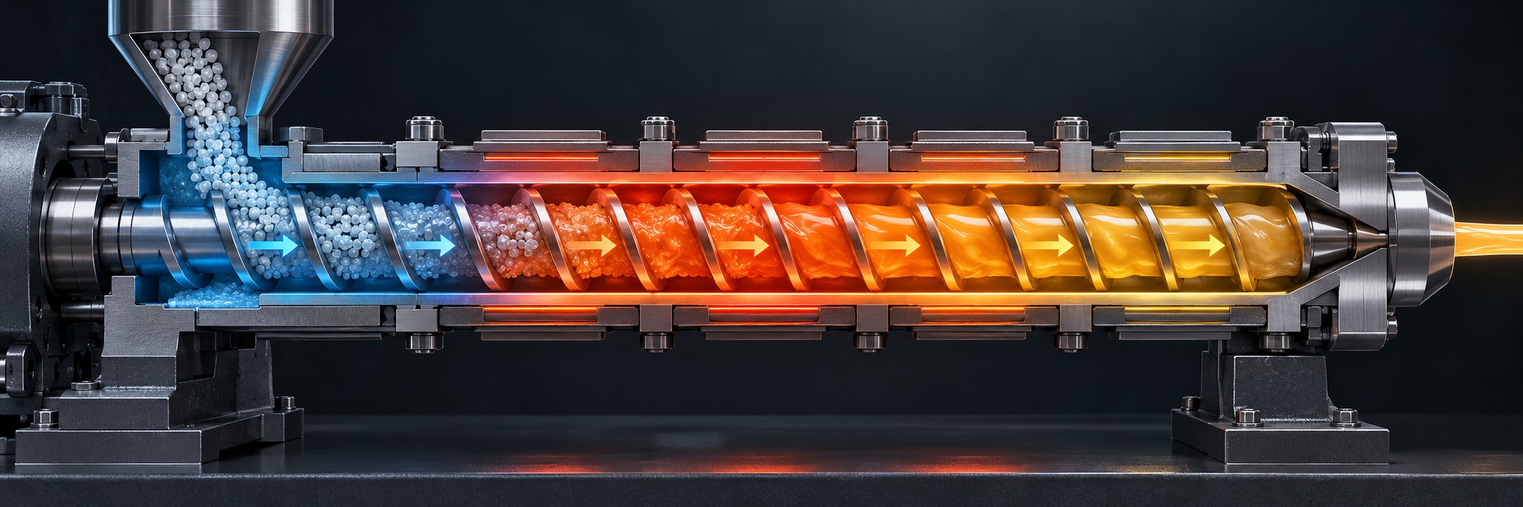
Think of the extruder barrel as a series of rooms, each with its own thermostat and its own job. Material passes through these rooms in sequence, and the temperature in each one must match the task being performed at that point along the screw.
- Feed zone (Zone 1). The first barrel section receives the raw powder blend or pellets. Temperatures here stay relatively low — typically 150-160 °C for PVC-WPC formulations — to prevent premature melting that would cause the material to stick and bridge over the screw flights. The goal is solids conveying: moving the blend forward under pressure without softening it enough to lose its grip on the barrel wall.
- Compression and melting zones (Zones 2-3). This is where the real work begins. Temperatures ramp up to 165-180 °C, and the decreasing channel depth of the screw compresses the material, forcing the polymer to melt and encapsulate the wood flour particles. Shear from screw rotation adds mechanical heat on top of barrel heating. Operators need to watch this zone closely because it is the easiest place for accumulated shear heat to push the blend past the wood-flour degradation ceiling around 200 °C.
- Mixing and homogenization zone (Zones 3-4). Temperature holds steady or rises very slightly — perhaps reaching 175-185 °C — while the screw design shifts to dispersive and distributive mixing elements. The goal is a uniform melt with no undispersed wood-flour clumps and no polymer-rich streaks. Temperature uniformity across the barrel circumference matters as much as the setpoint itself; a hot spot on one side of the barrel creates viscosity differences that distort flow symmetry inside the die.
- Degassing zone. Positioned between mixing and metering, this section features one or more vacuum vent ports. Temperature may dip slightly — 170-180 °C is common — to reduce melt fluidity and prevent the vacuum from pulling soft material into the vent opening. Here, steam and volatile gases are extracted before they can create bubbles or surface roughness in the finished profile.
- Metering zone (final barrel section). Temperature stabilizes or drops a few degrees below the mixing-zone peak — a rising-then-slightly-dropping profile is standard practice in WPC. This deliberate cool-down reduces the risk of wood-flour charring at the point where the melt has the longest residence time and the most accumulated thermal history. The metering zone's job is to deliver a consistent, uniform-pressure melt stream to the die.
The overall pattern — rising through the compression zone, holding or peaking through mixing, then easing back slightly through metering — is the signature temperature profile of WPC extrusion. It stands in contrast to standard PVC extrusion, where operators can often run a steadily rising profile without worrying about organic filler degradation. In a WPC profile extrusion machine, every zone's setpoint exists in tension with the one before it, and the operator's skill lies in reading melt temperature (not just barrel temperature) to confirm the blend is staying within its safe window.
Screw Speed, Backpressure, and Output Balance
Here is a counterintuitive truth about WPC extrusion: running the screw faster does not necessarily produce more good product. In standard plastics processing, higher screw speed often translates directly into higher throughput. With a WPC blend, though, every additional rpm generates additional shear heat inside the melt — heat that cannot escape through the barrel walls fast enough to prevent localized overheating. The wood flour doesn't forgive that extra energy. It chars.
That is why screw speeds on a typical conical twin-screw WPC line run between 15 and 35 rpm — far below the 40-80 rpm range common on a pure-PVC profile machine. Even on parallel twin-screw systems handling PE- or PP-based WPC, operators typically limit speed to the lower third of the machine's capability and rely on screw diameter and barrel length, rather than rotational speed, to hit their output targets.
Backpressure plays a related but separate role. It is the resistance the melt encounters between the screw tip and the die opening, and it directly affects melt density and homogeneity. Too little backpressure allows the melt to pass through partially unmixed, with air pockets and density variations that show up as weight inconsistencies and weak spots in the finished profile. Too much backpressure extends residence time, raising melt temperature and increasing the risk of thermal degradation.
The practical solution is to adjust backpressure through screen pack mesh size, die restriction, and screw geometry until the melt exits the die at a consistent pressure — usually monitored via a melt-pressure transducer mounted just upstream of the die adapter. When operators evaluate a factory price wPC profile extrusion machine, the presence and placement of that melt-pressure sensor is a quiet but telling indicator of build quality. Lines without it leave operators guessing at a variable they cannot afford to ignore.
In WPC extrusion, thermal control is more critical than speed. The processing window is narrower than standard plastics, and exceeding it by even a few degrees can degrade wood flour irreversibly. Output should be maximized by optimizing screw geometry and backpressure — not by pushing rpm.
Die Temperature and Calibration Vacuum Levels
The die is the last heated component the melt touches, and its temperature has an outsized effect on both surface quality and dimensional accuracy. If the die runs too hot, the profile exits too soft — it sags under its own weight and distorts before the calibration table can shape it. If the die runs too cold, the melt stiffens unevenly, producing flow lines, rough surfaces, and internal stress that causes warping after cooling. For most WPC formulations, die temperatures sit in the range of 170-185 °C, set a few degrees below the metering zone to begin the transition from molten to semi-rigid without premature solidification.
Uniform die temperature across the entire cross-section is critical. A profile die with four heater zones set to identical readings can still produce uneven flow if the die steel conducts heat differently around corners, thick sections, or thin walls. Operators often fine-tune individual die-zone heaters by 2-5 °C to balance flow rates across the profile geometry — a process sometimes called "die lip balancing" — until the extrudate exits at uniform speed across its full width.
Immediately after leaving the die, the still-soft profile enters a vacuum calibration sizing table. This piece of downstream equipment is where dimensional precision is locked in. Controlled vacuum pressure — typically in the range of -0.2 to -0.6 bar — draws the warm extrudate outward against precision-machined calibration plates while chilled water circulates through or around the calibrator to solidify the profile in its final shape. For hollow or multi-chamber WPC profiles, internal mandrels and independently controlled vacuum zones hold each cavity to its target dimensions.
WPC's lower melt strength compared to rigid PVC makes vacuum calibration setup especially demanding. The composite melt doesn't stretch and self-support as readily as pure PVC does, so vacuum levels need to be higher and more precisely regulated to pull the profile firmly against the calibrator walls without collapsing thin sections. Getting this balance right — die temperature, vacuum intensity, and cooling water flow — is what separates a high quality WPC floor profile extrusion machine from one that produces dimensionally inconsistent boards shift after shift.
When evaluating any line from a wpc profile extrusion machine factory in China or elsewhere, pay close attention to the number of vacuum calibration stages, the precision of vacuum regulation, and whether the cooling system allows independent water-temperature adjustment per calibration block. These details rarely appear on a price list, but they determine whether the profiles you produce will meet the tolerances your customers demand — or fall just short, board after board.
Dialing in temperature zones, screw dynamics, and calibration parameters transforms a well-prepared blend into a dimensionally stable profile. Yet even with every setpoint optimized, the journey isn't complete at the calibrator exit. The profile still has to travel through haul-off units, cutting stations, and optional finishing steps — each of which introduces its own potential for quality gain or loss.
Downstream Equipment and Its Role in WPC Profile Quality
The extruder and die shape the melt. Everything that follows determines whether that shape survives long enough to become a sellable product. In a WPC profile extrusion machine line, the downstream section is not a collection of passive conveyor stations — it is an active quality-control system where calibration, pulling force, cutting precision, and optional surface finishing all work in concert to lock in the profile's final dimensions, surface texture, and structural integrity.
Here is the full downstream sequence, listed in the order the profile passes through each station after leaving the die:
- Vacuum calibration and sizing table
- Spray or immersion cooling tanks
- Caterpillar or belt-type haul-off unit
- Flying saw or planetary saw cutting system
- Optional embossing unit (online wood-grain texturing)
- Automatic stacking or collection table
Each station plays a distinct role, and understanding what it does — and what goes wrong when it doesn't do it well — gives you far more insight into line performance than any brochure list of equipment names ever could.
Calibration and Sizing Tables
Imagine squeezing toothpaste from a tube: the soft ribbon holds its shape for a moment, but gravity and momentum quickly distort it. A WPC profile exiting the die faces the same challenge at a much larger scale. The extrudate is still soft, still cooling, and still vulnerable to sagging, swelling, or collapsing — especially in hollow or multi-chamber cross-sections. The vacuum calibration table is the first piece of equipment that intervenes to prevent all of that.
A vacuum sizing table applies negative pressure — typically in the range of -0.2 to -0.6 bar — to draw the still-pliable profile outward against precision-machined stainless-steel or brass sizing plates. Simultaneously, chilled water circulates through channels in the calibrator body or sprays directly onto the profile surface, rapidly cooling the outer skin and locking the geometry into place. For hollow WPC decking boards, internal sizing mandrels and independently controlled vacuum zones hold each cavity to its target dimensions, preventing the walls from caving inward under atmospheric pressure.
Why is this step especially demanding for WPC? Compared to rigid PVC, a wood-plastic composite melt has lower melt strength — it cannot stretch and self-support as readily during the transition from molten to solid. That means vacuum levels need to be higher and more precisely regulated. Too little vacuum and the profile shrinks away from the calibrator walls, emerging undersized or with rounded corners. Too much vacuum and thin-wall sections collapse or develop drag marks from excessive friction against the sizing plates. Operators at any WPC floor profile extrusion machine factory will tell you the same thing: calibration setup takes more trial runs with WPC than with pure polymer profiles, and once you find the sweet spot, you protect those settings carefully.
Multiple calibration stages — often two or three tables in series — are common on WPC lines. The first table handles primary sizing under the highest vacuum, the second continues cooling and dimensional stabilization, and a third may serve as an extended spray-cooling bath that brings the core temperature down far enough to prevent post-line warping. When evaluating the best WPC floor profile extrusion machine price, always check the number and length of calibration stages. A line offered with a single short calibration table at a cheap WPC floor profile extrusion machine price might seem like a bargain, but the dimensional instability it produces will cost far more in rejected boards.
Haul-Off Units and Speed Synchronization
The haul-off is the heartbeat of the downstream section. It pulls the cooled profile through every station at a controlled, constant speed — and that speed must be precisely synchronized with the extruder's output rate. Get the relationship right and every meter of profile receives the same amount of material, producing uniform wall thickness and consistent weight. Get it wrong and you'll see stretching, bowing, compression marks, or erratic dimensional variation that no amount of upstream adjustment can fix.
Most WPC lines use caterpillar-type haul-offs — two opposing tracks of rubber or polyurethane pads that grip the profile from top and bottom, pulling it forward with even, distributed contact. Belt-type haul-offs serve a similar function but use wide, continuous belts instead of individual pads, and they're often preferred for wider or flatter profiles like deck boards where uniform grip across the full width matters.
The critical variable is synchronization between extruder output and haul-off speed. If the haul-off pulls faster than the extruder delivers material, the profile stretches — walls thin out, weight per meter drops, and internal stresses build in that can cause warping after installation. If the haul-off runs too slowly, material backs up, the profile thickens or sags between the die and calibration table, and you risk jamming the calibrator.
WPC's composite nature makes it less forgiving of synchronization errors than pure polymer profiles. A rigid PVC profile has some elastic recovery — a brief speed mismatch can self-correct to a degree as the polymer relaxes. WPC, with its rigid wood-flour skeleton locked inside a polymer matrix, behaves more like a brittle solid once cooled past a certain point. Stretching or compressing a partially solidified WPC profile doesn't just change dimensions temporarily; it can fracture internal wood-polymer bonds, creating hidden weakness that manifests as cracking weeks or months later in service. That is why servo-driven haul-offs with closed-loop speed control are standard on any serious production line — they respond to load variations in milliseconds rather than seconds.
Cutting Systems and Profile-Specific Considerations
Extrusion is a continuous process. Customers need discrete lengths. The cutting system bridges that gap, and for WPC profiles, the choice of cutter and blade type has implications that go beyond simple logistics.
Two main cutting approaches dominate WPC profile lines:
- Flying saw cutters. These travel alongside the moving profile on a carriage, matching its speed during the cut and then returning to the start position. The profile never stops, so the line runs continuously without speed interruptions. Flying saws are the standard for high-output decking and cladding lines where volume is the priority and cut-end aesthetics are secondary because the boards will be trimmed on-site during installation.
- Planetary saws. These use a blade that orbits around the profile — or, in the case of a stationary planetary saw, the profile is briefly clamped and the blade rotates around it. Planetary saws produce cleaner, chip-free cuts and are preferred for decorative profiles, window frames, or any product where the end face is visible in the final application. They operate at slower cycle times than flying saws, which limits maximum line speed.
Regardless of the saw type, WPC's wood content creates a blade-wear dynamic that pure plastics lines never encounter. Wood flour and mineral fillers like calcium carbonate act as mild abrasives, dulling conventional steel blades far faster than unfilled polymer would. Carbide-tipped blades with high tooth counts — typically 60 to 80 teeth — are the standard choice for WPC cutting. They resist abrasive wear, maintain a clean edge longer, and reduce the risk of chipping or splintering that jagged cuts can cause on composite material. Operators should expect to replace or resharpen blades more frequently than on a plastics-only line, and budgeting for that consumable cost upfront avoids unpleasant surprises during production ramp-up.
Stacking, Embossing, and Post-Processing
The cut profile isn't always finished when it leaves the saw. Two optional downstream additions deserve mention because they add significant market value to the finished product:
- Online embossing units. Positioned just after the calibration table — while the profile surface is still warm enough to deform plastically — embossing rollers press a wood-grain texture into the board surface. This single step transforms a flat, uniform-looking composite board into a product that closely mimics the look and feel of natural timber. The embossing pattern, roller pressure, and surface temperature must all be controlled precisely; too cool and the pattern won't take, too hot and the board surface distorts beyond the desired texture depth.
- Automatic stacking tables. These collect cut-length boards, align them, and stack them into bundles ready for strapping and shipping. On high-output lines producing hundreds of meters per hour, manual stacking is simply not practical — and the risk of surface scratches or impact damage from manual handling undercuts the quality built into every upstream station.
Together, these downstream components form an integrated system where each station depends on the one before it. Calibration defines the shape. Haul-off maintains the flow. Cutting delivers the length. Embossing adds the finish. Stacking protects the product. Remove or underperform at any single station and the defects cascade forward — a lesson that becomes especially vivid when surface blisters, dimensional drift, or warped boards start appearing at the stacker end. Recognizing those defects and tracing them back to their true origin is itself a critical production skill, and it is one that the processing challenges ahead will address directly.
Common WPC Processing Challenges and How to Fix Them
You've selected the right extruder configuration, dialed in your temperature zones, and set your downstream equipment to spec. Production starts — and within the first hour, you spot rough patches on the profile surface, notice a slight bow developing in stacked boards, or find dark specks scattered across an otherwise clean run. What went wrong?
The reality is that even a well-configured WPC profile extrusion machine operates inside a tighter process window than any standard plastics line. Small deviations — a few percent moisture in the wood flour, a five-degree overshoot in one barrel zone, a vacuum calibration table running slightly uneven — produce defects that pure-polymer extrusion would shrug off. The key to fixing these issues fast is recognizing the defect pattern and tracing it to its most likely origin rather than adjusting multiple variables at once. As experienced troubleshooters know, changing temperature, screw speed, and haul-off speed simultaneously only obscures the real cause and creates new instability.
Below are the four most common defect categories in WPC profile extrusion, each with its root cause and practical corrective steps.
Surface Defects from Moisture and Volatile Off-Gassing
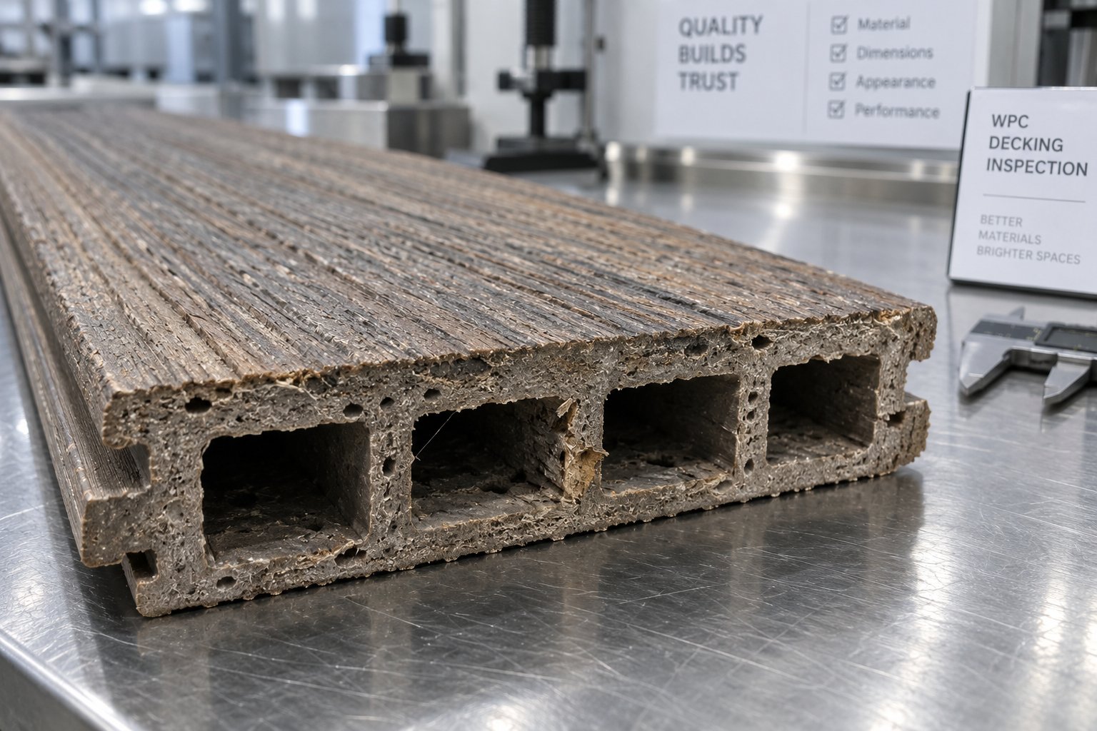
This is the defect you'll encounter most often — and the one with the most straightforward fix. When residual moisture in wood flour exceeds the safe threshold (typically 1-3% depending on formulation), it converts to steam inside the heated barrel. That steam escapes through the weakest path, which is usually the profile surface. The result? Bubbles, blisters, rough "orange peel" textures, silver streaks, and internal voids that weaken the profile structurally.
How do you confirm moisture is the culprit rather than something else? Look for these telltale signs:
- Defects appear randomly across the profile surface rather than in a consistent location.
- Bubbles or voids are visible when you snap a profile cross-section and inspect the broken edge.
- The problem worsens on humid days or after the wood flour has sat in an open container between shifts.
- A hissing or popping sound is audible near the die exit or vent port.
If those indicators line up, the corrective path is clear: verify that the wood flour dryer is operating at target temperature and retention time, test incoming flour with a moisture analyzer before it enters the mixer, and confirm that the sealed storage bin hasn't been left open. On the machine side, check that vacuum vent ports are unobstructed and pulling adequate vacuum — a clogged vent port mimics a moisture problem even when the flour itself is dry. Operators running a cheap price WPC profile extrusion machine sometimes discover that the vacuum pump is undersized for the line's throughput, which limits degassing effectiveness at higher output rates.
Die Pressure Fluctuations and Uneven Flow
Imagine watching the profile exit the die and noticing it speeds up, slows down, speeds up again — a rhythmic surging that produces thick-thin-thick variations along the profile length. This is die pressure instability, and it shows up as dimensional variation, surface waviness, and inconsistent meter weight that makes boards fail quality checks.
Several upstream causes feed into this single symptom:
- Inconsistent feeding. If the gravimetric feeder is starving or surging — perhaps because of wood-flour bridging in the hopper or bulk-density variation between batches — the extruder receives uneven material flow. Output fluctuates, and die pressure follows. The fix starts at the feed throat: clear any bridging, verify feeder calibration, and check that the crammer (if installed) is running at consistent speed.
- Temperature swings. A heater band cycling erratically or a failed thermocouple in one barrel zone creates localized viscosity changes in the melt. According to SPE rheological data, a 10 °C variation in barrel temperature can produce a 15-30% change in melt viscosity for common polymers — more than enough to cause visible surging. Cross-reference your pressure trace with barrel zone temperature logs to isolate which zone is drifting.
- Partially blocked screen packs. As the screen pack accumulates degraded material or mineral-filler particles, differential pressure rises progressively. Output drops between screen changes and spikes immediately after. If pressure events align precisely with screen change intervals, contamination buildup is the confirmed cause. Replace the screen pack, and if the problem recurs quickly, investigate whether wood flour charring upstream is generating excess carbon particles.
The golden rule here is the same one that applies across all extrusion troubleshooting: make one adjustment at a time, wait for the line to stabilize, and evaluate the result before changing anything else.
Profile Warping and Uneven Cooling
You cut a perfectly dimensioned board, stack it, and come back the next morning to find it bowed like a shallow arc. Or you pull a profile off the line and notice a gentle twist that makes it impossible to lay flat. Warping is one of the most frustrating WPC defects because it often doesn't reveal itself until after the profile has cooled completely — sometimes hours later.
The root cause is almost always differential cooling. When one side of a profile — top versus bottom, thick wall versus thin wall, capped surface versus uncapped core — cools and contracts faster than the opposing side, internal stresses build unevenly. Once the profile reaches ambient temperature and those stresses reach equilibrium, the board curves toward the side that contracted more.
As WPC manufacturers have documented, uneven extrusion cooling is a leading cause of board deformation — not an inherent product flaw. The corrective steps focus on balancing cooling rates:
- Verify that spray nozzles or water channels in the calibration table distribute cooling water evenly across the top and bottom of the profile. A blocked nozzle on one side creates exactly the asymmetric cooling that causes bowing.
- Adjust vacuum levels independently for upper and lower calibration plates if the equipment allows it — pulling harder on one side can compensate for asymmetric heat transfer in profiles with different wall thicknesses.
- Extend the cooling path. If the profile core is still warm when it reaches the haul-off, residual heat continues releasing after cutting, and post-line shrinkage becomes uneven. Adding a longer spray cooling tank or reducing line speed to allow more cooling time per meter often resolves warping that no calibration adjustment can fix.
- Check stacking practices. Boards stacked while still warm — especially if stacked unevenly or without spacers allowing air circulation — can warp under their own weight during final cool-down.
For operators evaluating a low price WPC profile extrusion machine, cooling-table length and the number of independent cooling zones are specifications that directly affect warp resistance in the finished product. A shorter line may cost less upfront, but if profiles consistently bow after cutting, the savings evaporate in rejected material.
Wood Flour Charring and Discoloration
Dark specks, brown streaks, or an overall shift in color toward a darker, muddier tone — these are the visible signatures of wood flour that has been thermally degraded inside the barrel. Once cellulose and lignin begin to break down, the charred particles cannot be "unburned." They embed in the profile permanently, and if the problem persists, the entire production run becomes unsellable.
Two mechanisms typically cause charring:
- Excessive barrel temperature. Even a single zone running 10-15 °C above its setpoint can push the wood component past its roughly 200 °C degradation threshold. This is especially common when heater band PID controllers are poorly tuned and overshoot during recovery after a cold start or material interruption.
- Excessive shear heat. Running the screw too fast generates frictional heat inside the melt that barrel cooling cannot extract quickly enough. The melt temperature — measured at the die adapter, not the barrel wall — may be 15-25 °C higher than barrel setpoints suggest. Operators who chase higher output by pushing rpm on a cheap WPC profile extrusion machine often encounter this problem before any other.
Corrective steps start with measurement: use a melt thermocouple or infrared pyrometer at the die exit to determine the actual melt temperature, not just the barrel surface reading. If the melt is running above 195 °C, reduce the highest barrel zone setpoints by 5 °C increments, allowing the line to stabilize for at least 10 minutes between changes. If barrel temperatures are already at target but melt temperature is still too high, reduce screw speed — output will drop, but so will scrap rate. Also inspect the screw and barrel for wear; worn flights increase clearances, which raises shear locally and creates hot spots that are invisible on barrel temperature displays.
For quick reference during production, the table below maps each major defect type to its most likely cause and the recommended first corrective action.
| Defect Type | Likely Cause | Recommended Corrective Action |
|---|---|---|
| Bubbles, blisters, rough surface | Residual moisture in wood flour; blocked or undersized vacuum vent | Verify wood flour moisture is below 1-3%; check vacuum vent port function and pump capacity |
| Internal voids or foaming | Excessive moisture; insufficient degassing; volatile additives | Improve drying; increase vacuum intensity; review additive package for volatile components |
| Dimensional surging (thick-thin variation) | Inconsistent feeding; temperature swings in barrel zone; screen pack saturation | Stabilize feeder; inspect heater bands and thermocouples; replace screen pack and log pressure trends |
| Bowing or arching along profile length | Asymmetric cooling — top vs. bottom temperature difference | Balance cooling water spray distribution; adjust upper/lower vacuum independently; extend cooling length |
| Twisting or helical warp | Uneven die flow or asymmetric calibration contact | Re-balance die zone temperatures; verify calibration plate alignment and contact uniformity |
| Dark specks or brown streaks | Localized barrel overheating; excessive shear heat from high screw speed | Reduce barrel zone setpoint by 5 °C increments; lower screw speed; measure actual melt temperature at die |
| Overall color shift (darker than standard) | Prolonged residence time; general thermal degradation across barrel | Reduce all barrel zones by 3-5 °C; check for material hang-up or dead zones; purge barrel thoroughly |
| Rough die lines (longitudinal streaks) | Die lip buildup; damaged or scored die land surface | Clean die lips; inspect die land for scratches or carbon deposits; polish if necessary |
Print this table and keep it near the operator console. In the heat of a production issue, having a structured first-response reference prevents the most common mistake in extrusion troubleshooting — changing three variables at once and losing track of which one actually solved the problem.
Most of these defects are process-related and correctable within a shift. A different category of problem, however, builds slowly over weeks and months rather than appearing overnight: the progressive wear of screws, barrels, and dies caused by the abrasive nature of wood flour and mineral fillers. That mechanical degradation erodes output quality so gradually that many operators don't recognize it until performance has already fallen well below the line's original capability.
Maintenance and Wear Management for WPC Extrusion Machines
A freshly installed WPC profile extrusion machine runs beautifully — tight tolerances, stable output, smooth surfaces. Six months later, output has quietly dropped by 10-15%, energy consumption has crept up, and operators find themselves nudging barrel temperatures and screw speeds to compensate for something they can't quite pinpoint. What changed? Nothing visible. Nothing sudden. The culprit is mechanical wear — the slow, silent erosion of screw flights and barrel bore surfaces by the very material the machine was built to process.
Unlike standard plastics extrusion, where screws and barrels can run for years with minimal degradation, WPC processing subjects these components to a relentless abrasive assault. Understanding why that happens, how to slow it down, and when to replace worn parts is arguably the most important long-term production skill any WPC line operator can develop.
Why WPC Extrusion Accelerates Screw and Barrel Wear
Think of wood flour as very fine sandpaper suspended in a viscous fluid. Every rotation of the screw drags millions of abrasive wood particles across the screw flight surfaces and along the barrel bore. That alone would accelerate wear compared to unfilled polymer processing. But most WPC formulations compound the problem by including mineral additives — calcium carbonate, talc, or titanium dioxide — that are harder than the wood flour itself and act as secondary abrasives grinding against metal surfaces under high pressure and temperature.
The abrasive nature of wood fibers and mineral fillers erodes screw flights progressively, reducing their outer diameter and increasing the clearance between the flight tip and the barrel wall. As that clearance widens, several performance problems cascade together:
- Reduced conveying efficiency. Material leaks backward over worn flight tips instead of being pushed forward, cutting effective throughput even when screw speed and feed rate remain unchanged.
- Inconsistent melt quality. Wider clearances reduce the compressive and shear forces the screw applies to the blend, leading to incomplete plasticizing, undispersed wood-flour clumps, and temperature inconsistencies within the melt.
- Higher energy consumption. The motor works harder to maintain output because a greater percentage of screw rotation is wasted on internal recirculation rather than productive forward conveyance. Operators who track specific energy consumption (kWh per kilogram of output) often notice a gradual rise of 8-15% before other symptoms become visible.
- Increased defect rates. As melt homogeneity deteriorates, surface defects, dimensional variation, and internal voids become more frequent — problems that look like process issues but are actually hardware degradation in disguise.
Barrel bore wear follows a similar trajectory. The inner surface erodes unevenly, often developing oval or tapered wear patterns concentrated in the high-pressure compression and metering zones where abrasive contact is most intense. Once the barrel bore exceeds its tolerance — typically when clearance over the screw flight exceeds twice the original specification — the barrel must be replaced or re-lined, regardless of external appearance.
Hardened and Bimetallic Solutions for Extended Service Life
Knowing that wear is inevitable doesn't mean accepting it passively. The metallurgy of the screw and barrel is the single biggest lever you can pull to extend service intervals and protect production consistency between replacements.
Three tiers of wear protection are common across the industry:
- Nitrided steel. The baseline treatment for most extruder screws and barrels. Gas nitriding creates a hard surface layer (typically 900-1,100 HV) that resists initial wear well but wears through relatively quickly under heavy abrasive loading. For lightly filled WPC blends running at moderate output, nitrided components may last 12-18 months before clearances drift out of tolerance.
- Bimetallic barrels. A step up in both cost and durability. Bimetallic barrels use centrifugal casting to bond a wear-resistant alloy liner — nickel-based, tungsten carbide, or iron-boron alloys — to the inside of a structural steel shell. The result is an inner surface that can withstand abrasive WPC blends three to five times longer than standard nitrided barrels. For any WPC profile extrusion machine supplier recommending long-term production setups, bimetallic barrels are effectively the minimum specification for serious operations.
- Hardened and coated screws. Screw flights can be hardfaced with stellite or tungsten carbide weld overlays on the flight tips and leading edges — the zones that see the most abrasive contact. Combined with a bimetallic barrel, this pairing creates a wear system where both the moving and stationary surfaces resist erosion simultaneously, preventing the scenario where a new screw installed into a worn barrel (or vice versa) wears out prematurely due to mismatched clearances.
When sourcing replacement conical twin screw barrels for WPC extrusion, precision matters as much as metallurgy. The barrel bore must match the screw geometry exactly, and the alloy liner must be uniform in thickness and hardness along the full barrel length. Specialists like NANHAIYA focus specifically on custom and replacement conical twin screw barrels engineered for stable plasticizing performance in WPC and PVC applications — the kind of purpose-built component that pays for itself by restoring original-specification output and extending the interval until the next replacement. For operators whose production depends on a conical twin-screw line, having a reliable barrel supplier on speed dial is not optional — it is a core element of uptime management.
Preventive Maintenance Schedules and Inspection Practices
Reactive maintenance — waiting until output drops noticeably or defects spike before inspecting wear parts — is the most expensive approach to managing a WPC line. By the time degradation is visible in product quality, the screw and barrel have already passed the point where correction is cheap. Preventive maintenance catches wear early, plans replacements during scheduled downtime, and keeps production quality consistent shift after shift.
Here are the key maintenance checkpoints every WPC extrusion operation should follow:
- Monthly: Record and trend motor amperage and specific energy consumption (kWh/kg). A rising trend signals increasing internal clearances even before product quality visibly deteriorates.
- Quarterly: Measure screw flight outer diameter at multiple points along the screw length using a micrometer or laser gauge. Compare against original-specification dimensions. Any zone showing more than 0.1-0.2 mm of flight diameter loss warrants closer monitoring.
- Quarterly: Inspect vacuum vent ports for material buildup or partial blockage. Clean thoroughly and verify vacuum pump performance. A clogged vent mimics moisture-related defects and masks the true condition of the degassing system.
- Semi-annually: Bore-gauge the barrel at feed, compression, metering, and vent zones. Compare readings against the manufacturer's tolerance chart. Pay special attention to the compression zone — this is where abrasive loading peaks and wear concentrates.
- Semi-annually: Inspect die land surfaces for scoring, carbon buildup, and dimensional erosion. Polish or replace die inserts as needed. A scored die land creates longitudinal streaks on every meter of profile until corrected.
- Annually (or per manufacturer recommendation): Pull the screws for a full visual inspection. Check for cracks at the root of flight tips, erosion at the kneading-element interfaces, and wear patterns that indicate misalignment or bearing issues in the gearbox.
- Ongoing: Lubricate gearbox bearings, thrust bearings, and drive-chain components per the manufacturer's schedule. Over-lubrication can contaminate the material, while under-lubrication accelerates bearing failure — either outcome leads to unplanned downtime.
- Ongoing: Maintain a spare-parts inventory that includes at least one replacement screw set and barrel, backup heater bands, thermocouples, and vacuum pump rebuild kits. WPC wear is predictable in trajectory but unpredictable in timing — having parts on hand turns a potential two-week wait into a same-day swap.
Whether you source your machine from a WPC profile extrusion machine supplier in China or from a European manufacturer, the maintenance principles are identical. What differs is the availability and lead time for replacement components. Operators purchasing from a wpc profile extrusion machine wholesaler should confirm during the buying process that wear parts — particularly screws and barrels — are available for expedited delivery. A wpc profile extrusion machine wholesaler in china that cannot ship replacement barrels within two to three weeks is a liability to any production schedule built around continuous operation.
Building a proactive maintenance culture around your extrusion line does more than prevent breakdowns. It creates a performance baseline — a clear record of what the machine delivers when components are within specification — that makes it far easier to diagnose problems, justify capital expenditure on upgrades, and plan production capacity with confidence. And that same forward-looking mindset applies not only to maintaining today's equipment but also to tracking the technological shifts that are reshaping what WPC profile extrusion machines can produce in the first place.
Emerging Trends Shaping WPC Profile Extrusion Technology
Maintaining today's equipment keeps a production line running. But the profiles rolling off that line five years from now will likely look, feel, and perform very differently from those being cut and stacked today. Three technological shifts are already reshaping what a WPC profile extrusion machine can deliver — and each one carries specific implications for equipment configuration, process control, and raw material sourcing that forward-thinking producers need to understand before the market demands it.
Co-Extrusion Technology for Capped WPC Profiles
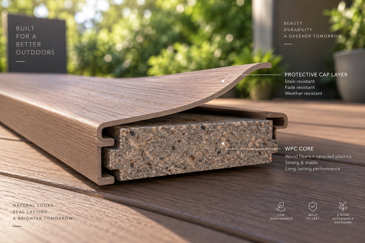
Picture a standard WPC decking board. It performs well structurally, but its surface is directly exposed to UV radiation, foot traffic, stains, and moisture. Over time, research on WPC weathering consistently shows discoloration and gradual mechanical property loss under prolonged outdoor exposure — a recognized weakness of conventional single-layer composites. Co-extrusion solves this by wrapping the WPC core in a thin, dense polymer cap layer during the extrusion process itself.
How does it work? A wpc co-extrusion profile machine adds a secondary extruder — typically a smaller single-screw unit — running alongside the main twin-screw extruder. The secondary extruder melts a cap-stock formulation, usually a high-performance ASA, HDPE, or modified PVC blend loaded with UV stabilizers, scratch-resistant additives, and color pigments. Both melt streams converge inside a co-extrusion die, where the cap material flows around the WPC core and bonds to it under heat and pressure before the combined profile enters the calibration table.
The results are significant. As co-extruded WPC decking manufacturers have documented, the outer cap layer is impervious to water and oil-based stains, blocks UV degradation of both the surface and the underlying core, and resists scratching far better than an uncapped composite surface. Color consistency improves dramatically because the pigment-rich cap shields the wood-flour core from the photochemical reactions that cause fading.
What does this mean for equipment? Producers upgrading to co-extrusion need to budget for a secondary extruder with its own drive, temperature control, and feeding system; a co-extrusion die engineered to merge two melt streams with uniform wall thickness around the full profile perimeter; and potentially upgraded calibration tooling sized for the slightly larger cross-section the cap layer adds. The investment is substantial, but the premium pricing capped profiles command in the market — often 20-40% above uncapped equivalents — typically justifies the capital outlay within one to two production seasons.
Foamed WPC Core Processing
Weight has always been one of WPC's competitive disadvantages against natural wood. A solid WPC deck board can weigh 30-50% more than its lumber equivalent, adding shipping cost, complicating handling, and increasing structural load on the supporting frame. Foamed-core extrusion directly addresses this by introducing a controlled cellular structure inside the profile, reducing density by 20-40% while maintaining the structural performance the application demands.
The process introduces a chemical blowing agent — typically an endothermic type like sodium bicarbonate or an exothermic azodicarbonamide compound — into the WPC formulation. As the blend reaches decomposition temperature inside the barrel, the blowing agent releases gas (usually CO2 or N2) that nucleates into tiny, uniformly distributed cells within the melt. When the material exits the die and pressure drops, those cells expand to create the final foam structure. Physical foaming, using direct gas injection through the barrel wall, is an alternative route that offers finer cell control but requires more sophisticated injection and metering hardware.
The machine adaptations are demanding. Temperature control must be exceptionally precise — even a 3-5 degree deviation can cause cell collapse on the cold side or uncontrolled blowout on the hot side. As process guides for PVC-WPC foam boards emphasize, foam structure is highly sensitive to melt temperature, pressure, die design, and cooling rate. Screw design shifts toward geometries that promote uniform gas distribution without creating excessive shear that ruptures cell walls prematurely. Calibration tooling may use a Celuka (skinning) approach, where the outer surfaces of the profile cool rapidly against the calibrator to form dense, hard skins while the core retains its cellular structure — combining surface hardness with lightweight interior in a single extrusion pass.
Foamed WPC profiles are gaining particular traction in decking, fencing, and trim applications where reduced weight lowers installed cost and makes DIY installation more practical — a growing market segment that wholesale WPC profile extrusion machine buyers are watching closely.
Sustainability and Recycled Material Integration
Perhaps the most consequential trend is not a new technology at all — it is the accelerating use of recycled feedstock in WPC formulations. And the extrusion machine sits at the center of that shift.
WPC production is inherently positioned for circular material use. The polymer component can come from recycled HDPE (milk jugs, detergent bottles), recycled PVC (window frame offcuts, pipe scrap), or recycled PP (automotive trim, packaging waste). The wood component can be sourced from sawmill residues, construction demolition waste, or furniture manufacturing scrap — materials that would otherwise go to landfill or incineration. A study on WPC composites using recycled HDPE and sawdust demonstrated that formulations containing 34% recycled high-density polyethylene and 60% wood sawdust produced profiles with tensile strengths within the 9.5-23.2 MPa range typical for commercial WPC products, confirming that recycled content does not inherently compromise mechanical performance when the formulation is properly optimized.
The machine-level challenges, however, are real. Recycled plastics arrive with variable melt flow indices, contamination levels, and additive histories. Recycled wood waste fluctuates in particle size, moisture content, and species composition. These inconsistencies demand adjustments across the entire line:
- Feeding: Gravimetric feeders become essential rather than optional, because bulk density variation in recycled streams can swing 15-25% between batches.
- Filtration: Melt filtration screens with finer mesh and automatic screen changers protect the die from contaminants — metal fragments, paper residue, or degraded polymer gels — that recycled feedstock inevitably carries.
- Degassing: Recycled polymers often contain residual volatiles from their previous life (printing inks, adhesive residues, absorbed odors). Additional or more aggressive vacuum venting capacity is needed to extract these volatiles without compromising surface quality.
- Temperature control: Recycled HDPE, for instance, may have a lower molecular weight and viscosity than virgin resin due to prior thermal processing, requiring adjusted barrel temperatures and screw speeds to achieve equivalent melt homogeneity.
WPC extrusion is one of the few manufacturing technologies that inherently supports circular material use — converting both plastic waste and wood waste into durable, long-life products that can themselves be recycled at end of service. Every advancement in machine filtration, degassing, and feeding precision expands the range of recycled content these lines can handle reliably.
For producers evaluating a wpc profile extrusion machine wholesale purchase or planning capacity expansion, these three trends — co-extrusion capping, foamed-core processing, and recycled-material integration — are not distant possibilities. They are active production realities on factory floors today, and the machines being specified right now should be capable of supporting at least one of these pathways without a full-line replacement. That forward compatibility is precisely the kind of consideration that separates a smart equipment investment from one that becomes obsolete before it pays for itself — a distinction the final section of this guide will help you make with confidence.
How to Evaluate and Select the Right WPC Extrusion Machine
You now understand the thermal constraints, the extruder configurations, the downstream precision, the wear dynamics, and the emerging capabilities shaping WPC profile production. The question shifts from "how does it work" to "how do I choose the right one?" This final section translates everything covered so far into a practical evaluation framework — one you can carry into supplier meetings, apply to a wpc profile extrusion machine pricelist, and use to separate genuinely capable equipment from lines that look impressive on paper but underperform on the factory floor.
Matching Machine Configuration to Your Profile Type
Before requesting wpc profile extrusion machine quotes from any supplier, define exactly what profiles you intend to produce. This sounds obvious, yet a surprising number of buyers start with machine specs and work backward toward the product — a sequence that almost guarantees mismatched equipment.
Different profile types impose fundamentally different demands on the line:
- Hollow profiles (decking boards, railing posts, fencing) require dies with internal mandrels, multi-zone vacuum calibration tables capable of holding each cavity independently, and haul-offs with adjustable grip pressure to avoid crushing thin walls during pulling.
- Solid profiles (trim boards, skirting, battens) simplify die and calibration design but demand higher extruder output per meter because there are no voids to reduce material consumption. Drive torque and cooling capacity must scale accordingly.
- Co-extruded capped profiles need a secondary extruder, a co-extrusion die, and downstream calibration tooling sized for the added cap-layer thickness. If co-extrusion is even a possibility for your product roadmap, confirm that the main extruder frame and control system can accommodate a secondary unit without a complete line redesign.
- Foamed-core profiles require precise temperature zoning, specialized screw geometry for uniform cell distribution, and calibration setups that create dense surface skins while preserving the lightweight cellular core. Not every standard WPC line can be retrofitted for foaming — the screw design and barrel venting layout need to support it from the outset.
Imagine buying a car without knowing whether you need a pickup truck or a sedan. The same logic applies here. Define the product first, then evaluate machines against that definition — not the other way around.
Key Specifications to Evaluate Beyond the Brochure
Brochures highlight output capacity, motor power, and screw diameter. Those numbers matter, but they tell you almost nothing about how well the machine handles the specific demands of WPC processing. When reviewing a wpc profile extrusion machine for sale — whether from a local distributor or a china wpc profile extrusion machine for sale listing — dig deeper into these criteria:
- Screw and barrel metallurgy. Is the barrel bimetallic-lined for abrasion resistance, or standard nitrided steel? Are screw flights hardfaced with tungsten carbide or stellite overlays? For WPC, this is not an upgrade — it is a baseline requirement that directly determines how many months of consistent production you get before wear degrades output quality.
- Number and placement of vacuum venting ports. A single atmospheric vent is inadequate for WPC. Look for at least one, preferably two, vacuum vent positions along the barrel — one in the compression zone and one near the metering zone — each connected to a dedicated vacuum pump with adjustable intensity.
- Drive torque rating relative to target output. Compare the gearbox torque specification (in Nm) against the output you need. A machine rated at 500 kg/h for pure PVC may only deliver 350 kg/h with a 50% wood-flour WPC blend because the higher melt viscosity consumes more torque at every screw rpm. Ask the supplier for WPC-specific output data, not just polymer-only ratings.
- Temperature zone count and control precision. More zones mean finer control over the barrel temperature profile — critical when the processing window is as narrow as WPC demands. Verify that each zone uses independent PID controllers with thermocouple feedback, not simple on-off heater switching.
- Availability of custom or replacement wear parts. This is the specification most buyers overlook during purchase and regret during production. Can the supplier or a third-party specialist deliver replacement screws and barrels within two to three weeks? If the answer is vague, your uptime is at risk the moment wear crosses the tolerance threshold.
When comparing wholesale price WPC profile extrusion machine options across multiple suppliers, resist the temptation to rank purely on cost. A line priced 15% below the competition but equipped with nitrided-only barrels and a single vent port will cost far more in downtime, scrap, and early component replacement than a slightly more expensive machine built with WPC-grade metallurgy and proper degassing from the start.
Building a Reliable Supply Chain for Long-Term Production
Purchasing the machine is the beginning of the relationship, not the end. WPC extrusion accelerates wear on screws, barrels, and dies faster than any unfilled polymer process — a reality covered extensively in earlier sections. That accelerated wear makes your spare-parts supply chain a production-critical asset, not an afterthought.
Think of it this way: your extruder runs 20 hours a day, six days a week. Screw flight wear reaches the replacement threshold after 14 months. If sourcing a replacement barrel takes eight weeks because you never established a supplier relationship, you face a painful choice — run degraded quality until the part arrives, or shut down and lose revenue. Neither option is acceptable.
The solution is straightforward: identify and qualify component suppliers before you need them. For conical twin-screw WPC lines — the dominant configuration for PVC-based profiles — this means having a trusted source for precision-matched conical twin screw barrels that meet the exact bore dimensions, alloy specifications, and taper geometry your machine requires. Specialists like NANHAIYA serve exactly this niche, providing custom and replacement conical twin screw barrels engineered for stable plasticizing performance in WPC and PVC extrusion applications. Establishing that relationship early — ideally during the machine commissioning phase — means you have dimensional drawings on file, alloy grades confirmed, and lead times locked in before the first sign of wear ever appears on a production report.
Beyond barrels and screws, a complete spare-parts strategy for WPC production should also include backup heater bands and thermocouples, vacuum pump rebuild kits, calibration sizing plates matched to each profile die, and carbide-tipped saw blades in sufficient quantity to avoid mid-run blade changes. Producers sourcing equipment through a wpc profile extrusion machine wholesale in china channel should verify spare-parts availability and shipping logistics during the initial purchase negotiation — not six months later when a worn barrel forces an emergency order.
The technical knowledge in this guide — from raw material preparation through extruder selection, process parameter control, downstream precision, troubleshooting, wear management, and emerging technology — exists to serve one practical goal: helping you invest in equipment that produces consistent, high-quality WPC profiles profitably over the long term. Use it to ask better questions, evaluate wholesale wpc profile extrusion machine quotes with sharper criteria, and build a production operation where machinery, materials, maintenance, and supply chain all work together rather than against each other. That integration is what separates a factory that merely owns a WPC line from one that truly masters it.
Frequently Asked Questions About WPC Profile Extrusion Machines
1. What is the difference between a conical twin screw and a parallel twin screw extruder for WPC profiles?
A conical twin screw extruder uses two tapered, counter-rotating screws that deliver high torque at low speed (30-150 rpm), making it the dominant choice for PVC-based WPC formulations. Its geometry naturally compresses material and handles low-bulk-density wood-flour blends efficiently. A parallel twin screw extruder features constant-diameter co-rotating screws running at higher speeds (400-600 rpm), excelling at intensive distributive mixing for PE- and PP-based WPC or compounding operations. The conical design offers a compact footprint and gentler thermal processing, while the parallel configuration provides superior mixing for complex formulations but generates more shear heat that must be carefully managed to avoid wood flour degradation.
2. Why can't a standard plastic extruder be used for WPC profile production?
Standard plastic extruders lack three critical capabilities that WPC processing demands. First, wood flour degrades above approximately 200 degrees Celsius, requiring tighter temperature control across every barrel zone than conventional plastics lines provide. Second, adding 30-70% wood flour dramatically increases melt viscosity, demanding motors and gearboxes with significantly higher torque ratings operating at lower screw speeds. Third, residual moisture in wood flour converts to steam during processing, causing bubbles and surface defects unless the barrel includes dedicated vacuum venting ports — a feature rarely found on standard equipment. These overlapping constraints mean every component in a WPC line must be purpose-engineered for the composite material.
3. How do you prevent wood flour charring and dark specks during WPC extrusion?
Wood flour charring results from either excessive barrel temperature or excessive shear heat generated by high screw speeds. To prevent it, measure the actual melt temperature at the die exit using a melt thermocouple or infrared pyrometer rather than relying solely on barrel wall readings. If melt temperature exceeds 195 degrees Celsius, reduce the highest barrel zone setpoints in 5-degree increments, allowing at least 10 minutes for stabilization between changes. If barrel temperatures are already at target but the melt remains too hot, lower screw speed to reduce frictional heat generation. Additionally, inspect screws and barrels for wear, as worn flights increase local shear and create hot spots invisible on standard temperature displays. Using bimetallic barrels and hardfaced screws from specialists like NANHAIYA can help maintain tighter clearances longer, reducing shear-induced overheating.
4. What moisture level should wood flour reach before entering a WPC extrusion line?
Wood flour should be dried to below 1-3% moisture content before entering the blending or extrusion stage, with PVC-based WPC formulations typically requiring the lower end of that range due to PVC's sensitivity to steam-driven porosity. Raw wood flour from suppliers usually carries 5-8% moisture, so dedicated drying equipment — either hot-air rotary dryers for high-volume operations or flash dryers for fine-mesh flour — is essential. After drying, store the flour in sealed bins because wood flour is hygroscopic and can reabsorb ambient moisture within hours. Skipping or shortcutting the drying step is the single most common cause of WPC extrusion defects including bubbles, blisters, rough surfaces, and internal voids.
5. How often should screws and barrels be inspected on a WPC profile extrusion machine?
For WPC lines, screw flight outer diameter should be measured quarterly at multiple points along the screw length using a micrometer or laser gauge, with any zone showing more than 0.1-0.2 mm of flight diameter loss flagged for closer monitoring. Barrel bore gauging should occur semi-annually at the feed, compression, metering, and vent zones, paying special attention to the compression zone where abrasive wear concentrates. Monthly trending of motor amperage and specific energy consumption (kWh per kg) provides an early warning of increasing internal clearances before product quality visibly deteriorates. Full screw pull-and-inspect should happen annually, checking for cracks at flight tip roots and wear patterns indicating gearbox misalignment. Maintaining a spare screw set and barrel on hand is strongly recommended since WPC wear timelines are predictable in trajectory but variable in speed.
Written by
Nanhaiya Technical Team
Zhoushan Nanhaiya Plastic Machinery Co., Ltd.
The Nanhaiya technical team supports screw and barrel manufacturing projects through application review, technical communication, custom manufacturing coordination, and production and quality control.
Discuss Your Application
Related Articles
More insights on screw barrel technology and plastics processing.
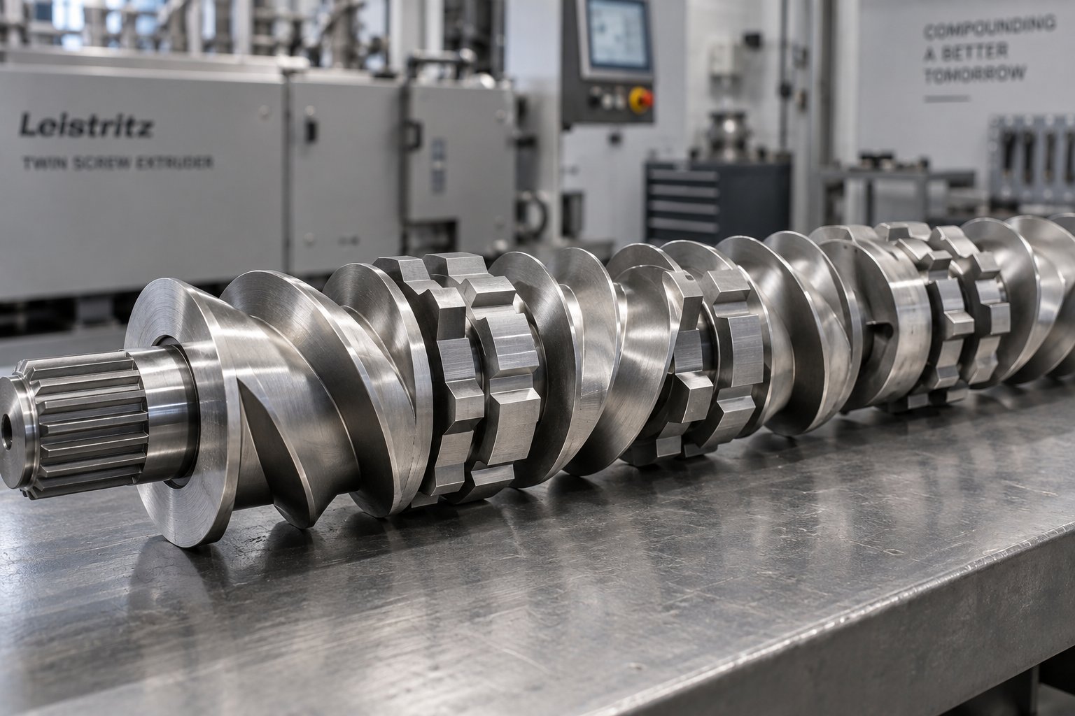
Twin Screw Extruder Screw Decoded: Geometry, Wear & Profile Fixes
Oct 14, 2026
Master twin screw extruder screw design: geometry parameters, kneading block stagger angles, element classification, wear mechanisms, and profile troubleshooting fixes.
Read Article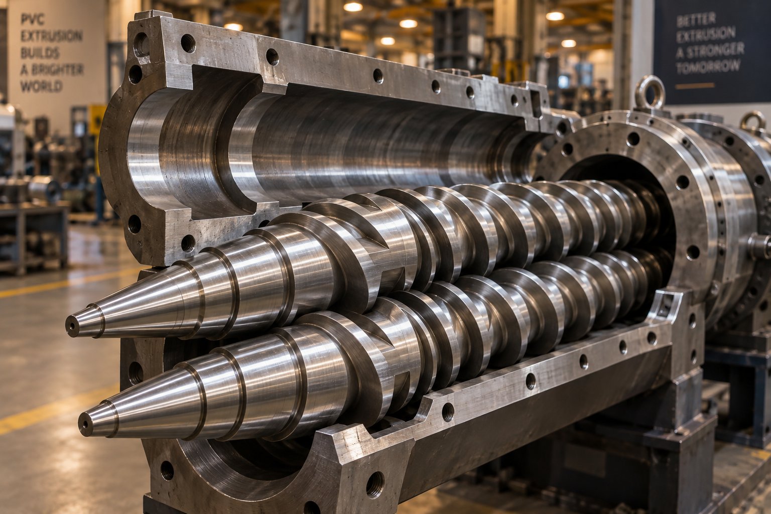
Your Extruder Screw Barrel For PVC Is Burning Resin — Here's Why
Oct 14, 2026
PVC burns resin when screw barrel geometry, metallurgy, or temperature zoning is wrong. Learn the exact specs, alloys, and wear fixes for PVC extrusion.
Read Article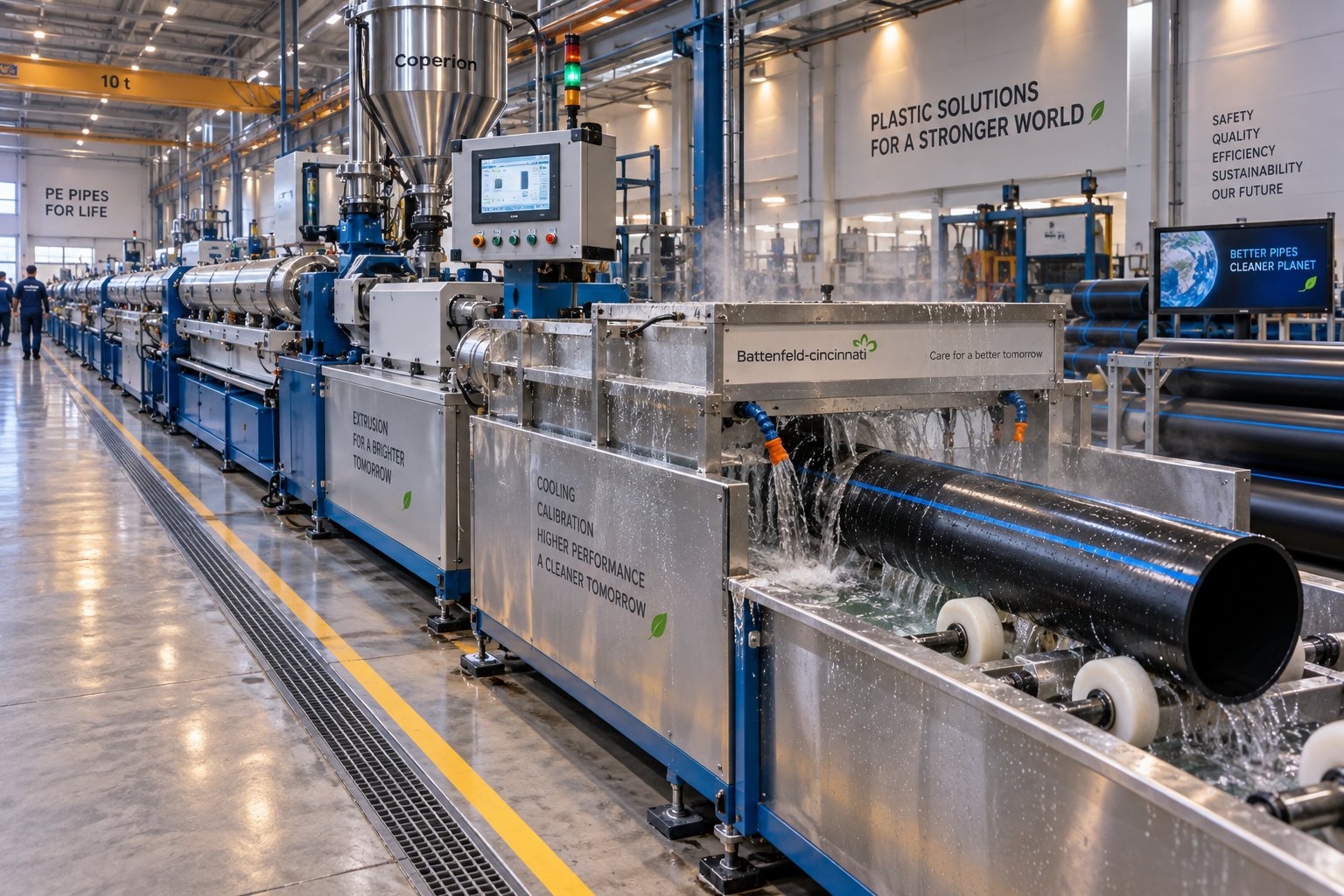
Plastic Pipe Extruder Decoded: Screw Design to Flawless Pipe
Oct 13, 2026
Learn how a plastic pipe extruder works — from screw and barrel design to material-specific processing, defect troubleshooting, and line sizing for PVC, HDPE, and PP-R pipe.
Read ArticleLooking for something else?
Search by material, symptom or product and jump straight to the relevant page.
These are navigation suggestions based on keyword matching — not a quotation, not a delivery commitment, and not a substitute for engineering review. Final specification is confirmed by our engineers against your drawings and processed material.
Need help with screw barrel selection?
Share your machine model, processed material and application. Our team can help with pricing and technical support.