

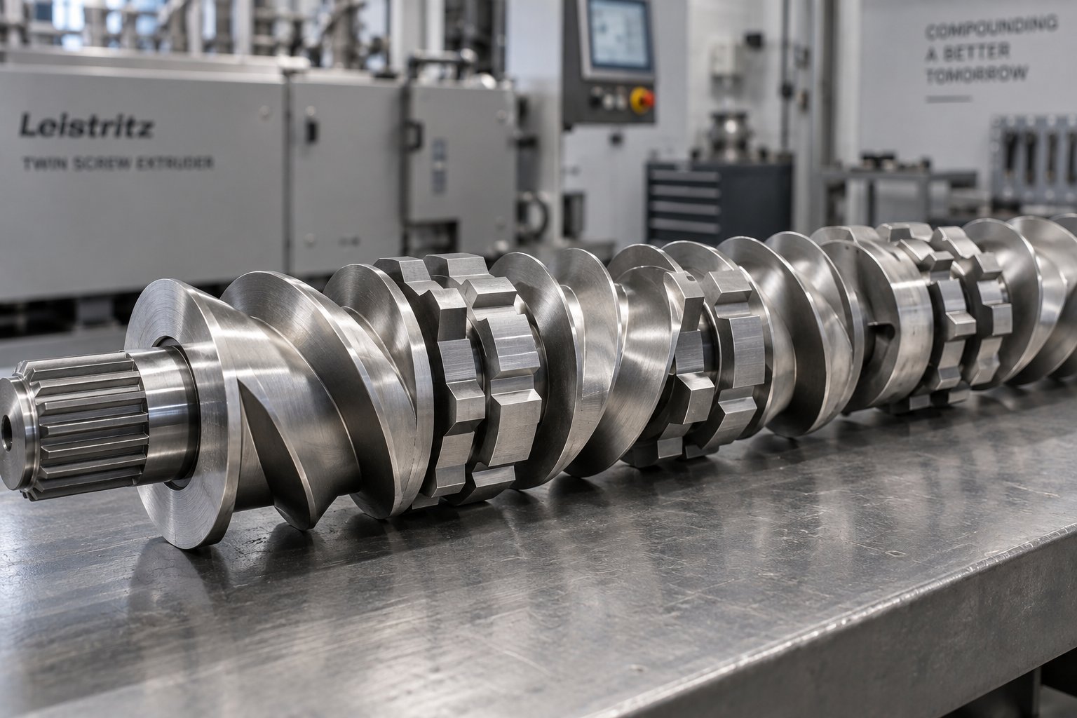
Twin Screw Extruder Screw Fundamentals and Why They Matter
Imagine a single component inside your extruder that dictates melt temperature, mixing quality, throughput, and pressure at the die — all at once. That component is the twin screw extruder screw. It is not a single machined part, though. It is a modular assembly, and understanding the distinction between its shaft and its elements is the first step toward mastering twin screw extrusion.
What Is a Twin Screw Extruder Screw
A twin screw extruder screw is a modular assembly consisting of a splined shaft onto which interchangeable screw elements — conveying segments, kneading blocks, and specialty mixing or sealing components — are mounted in a specific sequence to form a complete screw profile that controls material conveying, melting, mixing, devolatilization, and pressure generation inside the barrel.
The shaft itself is a torque-transmitting spine, typically featuring a splined or keyed profile that locks each element in rotational alignment. The elements are the functional parts: helical conveying flights that push material forward, lobed kneading discs that shear and blend it, and reverse-pitched segments that create back pressure and melt seals. A screw profile, then, is simply the specific arrangement of these elements along the shaft — and it can be disassembled, rearranged, and rebuilt to suit a completely different formulation or process goal.
This modularity is what separates a twin-screw extruder from most single-screw machines. Rather than committing to one fixed geometry, processors can swap individual segments to fine-tune shear intensity, residence time, and fill level zone by zone. Need more dispersive energy for pigment deagglomeration? Add a kneading block with a steeper stagger angle. Running a shear-sensitive recycled feedstock? Replace aggressive mixing elements with gentler distributive components. The same extruder hardware behaves very differently depending on how its screws are configured.
Why Screw Design Determines Process Performance
Inside the barrel, the extruder screw is the primary driver of material transformation. Every critical processing parameter traces back to element selection and arrangement. Screw design controls mass throughput, pressure profile from feed to die, melting rate, distributive and dispersive mixing quality, residence time distribution, temperature development from viscous shear, degassing efficiency, and final product consistency.
Think of the screw profile as a recipe layered on top of your formulation recipe. A typical twin screw configuration moves material through distinct process zones — solids conveying, melting, mixing, devolatilization, and metering — each shaped by the specific elements placed there. Coarse-pitch conveying elements grip pellets or powder at the feed throat. Kneading blocks downstream generate the shear and elongational flow needed to melt and blend. Reverse elements seal pressure zones for vacuum venting. Tight-pitch segments at the end meter melt to the die at stable pressure.
Change one element in this sequence and you shift the balance of shear, temperature, and residence time across the entire barrel. That sensitivity is both the challenge and the power of twin screw design. The sections ahead break down every element type, geometric parameter, and configuration strategy you need to make that power work for your process — from kneading block stagger angles to wear-driven replacement schedules.
Key Screw Geometry Parameters and Terminology Demystified
Conversations about twin screws often stall over terminology. One engineer says "screw" meaning the entire assembly; another means a single helical segment. A spec sheet lists Do/Di ratio, but the person reading it confuses outer diameter with flight depth. These misunderstandings are not trivial — they lead to ordering errors, misconfigured profiles, and process problems that could have been avoided with a shared vocabulary. This section lays that foundation.
Start with the most common mix-up. The screw shaft is the splined steel core that transmits torque from the gearbox. Screw elements — sometimes called segments — are the functional pieces that slide onto that shaft: conveying flights, kneading blocks, mixing discs, and sealing components. When someone refers to "the screw," they typically mean the complete assembly of shaft plus elements. When they say "segment" or "element," they mean one individual piece. In many extruder twin screw platforms, these elements are fully interchangeable, which is why getting the geometry labels right matters before you swap anything.
Essential Screw Geometry Terminology Explained
Twin screw extruder screw geometry is described by a handful of interdependent parameters. Each one influences how material flows, shears, and builds pressure inside the extrusion barrel. The table below defines the critical terms you will encounter in element catalogs, OEM drawings, and process engineering discussions around twinscrew systems.
| Parameter | Definition | Typical Range / Significance |
|---|---|---|
| OD (Outer Diameter, Do) | Maximum diameter of the screw element measured at the flight tip. | Defines the bore size pairing with the barrel; ranges from ~12 mm (lab) to 400+ mm (production). |
| ID (Inner Diameter, Di) | Diameter at the root of the screw channel — the bottom of the flight. | Determines free volume available for material; always smaller than OD. |
| Do/Di Ratio | Ratio of outer diameter to inner diameter. Indicates the relative channel depth. | Common range: 1.40 to 1.80. Higher ratios yield deeper channels and greater free volume; lower ratios produce shallower channels with higher shear. |
| L/D Ratio | Total processing length of the barrel divided by the screw outer diameter. | Typical range: 24:1 to 52:1. Longer L/D provides more residence time and zone flexibility. |
| Pitch | Axial distance the flight advances in one full 360° revolution. Often expressed relative to diameter: 1D, 1.5D, or 2D pitch. | 1D pitch = one diameter per turn. Larger pitch moves material faster with less fill; smaller pitch increases fill and pressure. |
| Flight Depth (h) | Radial distance from the flight tip down to the screw root: h = (Do − Di) / 2. | Directly controls channel volume and shear rate. Deeper flights reduce shear; shallower flights intensify it. |
| Flight Width (e) | Thickness of the helical flight measured along the axial direction at the tip. | Wider flights reduce open channel area but increase wiping surface. Typically a small fraction of pitch. |
| Tip Clearance (δ) | Radial gap between the flight tip and the inner barrel wall. | Usually 0.1–0.3 mm on new elements. As clearance increases through wear, leakage flow rises and mixing efficiency drops. |
| Helix Angle (θ) | Angle between the flight and a plane perpendicular to the screw axis. Determined by pitch and diameter. | Steeper helix angles (larger pitch) increase conveying velocity; shallower angles raise pressure generation capacity. |
You will notice that several of these parameters are mathematically linked. Flight depth derives directly from Do and Di. Helix angle is a function of pitch and screw radius. Change one dimension on a spec sheet and you inevitably shift others — which is exactly why understanding the full parameter set prevents costly mismatches when configuring screw extruders.
Understanding Pitch and L/D Ratio Impact on Processing
Pitch is arguably the most intuitive lever a processor can pull. A 2D pitch element (where pitch equals twice the outer diameter) covers more axial distance per revolution. Material travels through it quickly, fill level stays low, and shear exposure is brief. Shift to a 1D pitch element and everything reverses: the channel fills more completely, residence time in that zone stretches, and the material experiences significantly higher shear rates because the same rotational speed now acts on a shorter axial path. A 1.5D pitch sits in the middle and is the workhorse choice in many general-purpose compounding profiles.
These relationships are not merely directional. Research on corotating twinscrew extruders demonstrates that the average shear rate in a screw channel depends on both the drag component (driven by screw speed and helix angle) and the pressure-flow component (driven by local pressure gradients). In left-handed or reverse elements — where material is pushed upstream — the pressure gradient is always negative and substantially larger, producing shear rates three to four times higher than the simple drag-flow estimate alone would suggest. Ignoring that pressure term, as many simplified calculations do, leads to a significant underestimation of actual shear.
L/D ratio, on the other hand, governs the total real estate available along the barrel for all process zones combined. A 32:1 L/D extruder gives you roughly a third more zone length than a 24:1 machine with the same bore diameter. That extra length means you can insert additional kneading sections, longer devolatilization zones, or gentler melting transitions — all without compressing other zones. For complex formulations requiring multiple side feeds, vacuum ports, and staged mixing, L/D ratios of 40:1 to 52:1 are common. Shorter ratios suit simpler processes like single-component pelletizing where minimal mixing is needed.
Pitch and L/D do not operate in isolation. A short-pitch element placed in a long-barrel machine behaves differently than the same element in a compact system, because upstream and downstream conditions — fill level, pressure history, melt state — all interact. That interaction is precisely what makes twin screw profile design a system-level discipline, which the next section addresses by classifying every element type you might place along that profile.
Complete Screw Element Classification From Conveying to Specialty
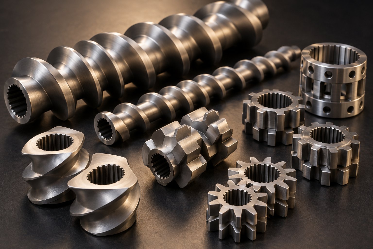
Every element sitting on a splined shaft serves a specific purpose — transport material, melt it, mix it, seal it, or build pressure behind it. Yet many processors treat element selection as guesswork, partly because no single resource organizes all element types into a clear, functional classification. That gap ends here. Below is a systematic breakdown of every major screw element category used in twin screw extruders, what each one does, where it belongs in the profile, and why it matters to your process outcome.
Conveying Elements and Their Role in Material Transport
Conveying elements are the workhorses of any screw extruder profile. They feature helical flights wrapped around a cylindrical body, and their sole job is to grab material and push it forward along the barrel. You will find them in virtually every zone, but they dominate the feed section and the metering section at the discharge end.
What makes one conveying element different from another? Pitch. A large-pitch conveying element — say, a 2D pitch — moves bulk material rapidly with minimal fill and low shear. This makes it ideal for the feed zone, where pellets, powder, or flakes need quick transport away from the hopper throat to prevent bridging. At the opposite end of the profile, a tight-pitch element like a 1D or even 0.5D pitch compresses material, raises fill level, and generates forward pressure to push melt through the die. NC State Extension research confirms that conveying ability decreases with decreasing pitch, while pressure build-up in the conveying direction increases — a direct trade-off that processors must balance zone by zone.
In the twin screw extrusion process, conveying elements also serve a critical role around side feeders and vacuum ports. Deep-flight, high-pitch segments placed beneath a side stuffer create the open volume needed to accept downstream additives like fillers or glass fiber. Similarly, deep-channel conveying elements positioned under a vacuum barrel vent keep fill level low so volatiles can escape the melt surface efficiently.
- Large-pitch conveying elements (1.5D–2D pitch): Primary function is rapid material intake. Placed at the feed zone and downstream of side feed openings. Key design variable is pitch length relative to screw OD.
- Standard-pitch conveying elements (1D pitch): Balanced transport and moderate pressure generation. Used as transition elements between functional zones — between kneading sections and devolatilization zones, for example.
- Tight-pitch conveying elements (0.5D–0.75D pitch): Maximize fill level and pressure build-up. Positioned at the metering zone ahead of the die or before restrictive elements. Key design variable is flight depth relative to the tighter pitch.
A useful way to think about it: conveying elements are the connective tissue of your screw profile. They do not transform material the way kneading blocks do, but without them, nothing reaches those kneading blocks — and nothing exits the die at stable pressure. Even in a twin screw auger used for simpler material handling, the pitch-to-function relationship holds: wider pitch for speed, tighter pitch for pressure.
Mixing Elements and the Dispersive vs Distributive Distinction
Here is where the real processing action happens. Mixing elements — primarily kneading blocks and specialized mixing discs — are responsible for melting, blending, and homogenizing material inside the barrel. To configure them correctly, you need to grasp one fundamental distinction: dispersive mixing versus distributive mixing.
Dispersive mixing breaks things down. It applies high shear stress to rupture agglomerates, deagglomerate pigment clusters, or fracture filler particles into smaller sizes. Picture carbon black bundles being torn apart under intense mechanical force — that is dispersive action. Distributive mixing, by contrast, spreads things out. It redistributes already-small components evenly throughout the melt without applying destructive shear. Imagine folding a ribbon of color concentrate into a clear polymer until the distribution is uniform — that is distributive action.
Why does this matter for element selection? Because the geometry of each mixing element tilts the balance toward one type of mixing or the other.
- Kneading blocks (wide disc — KBW type): Full-width discs on both sides generate high dispersive shear. The material is squeezed through narrow gaps between disc tips and the barrel wall, creating intense stress fields. Best suited for melting crystalline polymers and breaking down tough agglomerates. Typically placed in the plastication and primary mixing zones.
- Kneading blocks (narrow disc — KP type): Half-width discs provide more splitting and recombining of flow streams, favoring distributive mixing. Material is divided and reoriented more frequently, achieving homogeneity without excessive shear heating. Ideal for blending heat-sensitive additives or creating uniform color distribution.
- Toothed mixing elements (TME / ZME): These elements feature rows of teeth rather than continuous flights or lobed discs. They convey forward while providing efficient distributive mixing with minimal dispersive shear. NC State's screw profile research notes that toothed mixing elements (designated as Z elements) score well on distributive mixing while showing essentially zero dispersive effect — making them the go-to choice when you need blending without particle breakdown. Commonly placed before compression zones to homogenize solid-liquid ingredient combinations.
- Screw mixing elements (SME): Slotted or grooved flight elements that create cross-channel flow for gentle distributive action. These elements maintain some conveying capability while redirecting melt streams across the flight, and they fit naturally into profiles where both forward transport and mild mixing are needed simultaneously.
Selecting between dispersive and distributive elements is not an either-or decision. Most screw extrusion profiles use both types in sequence — aggressive kneading blocks upstream to melt and deagglomerate, followed by gentler distributive elements downstream to homogenize the melt before shaping.
Reverse Elements and Specialty Sealing Components
Forward-conveying and mixing elements handle transport and blending. But certain process functions — creating melt seals for vacuum venting, increasing residence time for reaction or absorption, and intensifying localized mixing — require elements that push material backward. That is the role of reverse elements and specialty sealing components.
- Reverse (left-handed) conveying elements: These are standard helical conveying elements with opposite-hand pitch. Instead of pushing material toward the die, they push it upstream. The result is a localized pressure dam: material accumulates against the reverse element, fill level spikes to 100%, and a melt seal forms. This seal is essential upstream of vacuum ports because it prevents air from being sucked backward through the barrel. Reverse elements are designated with an "L" suffix (e.g., SE 20/20 L) and are typically kept short — their length is generally less than one screw diameter — to avoid excessive pressure peaks and mechanical overload.
- Reverse kneading blocks: Kneading discs staggered in the reverse direction combine high shear mixing with back pressure. They create the most restrictive flow condition of any standard element, ensuring maximum residence time and energy input in the zone immediately upstream. This makes them powerful but potentially problematic: overuse generates excessive melt temperature and torque spikes.
- Blister rings: Solid cylindrical elements with no flights or channels. Material is forced through a thin annular gap between the blister ring and the barrel wall, creating a pressure seal and a brief burst of elongational flow. Blister rings are more restrictive than reverse conveying elements and are used where an absolute melt seal is needed — typically before the first vacuum port in devolatilization-intensive profiles.
- Screw seals: Similar in function to blister rings but designed with a slight clearance profile that allows controlled leakage. They separate pressure zones without the abrupt restriction that a full blister ring imposes, and they are often preferred in processes where gentler sealing protects shear-sensitive polymers.
Understanding this full classification — conveying, mixing (dispersive and distributive), reverse, and specialty sealing — gives you the vocabulary and functional logic to read, design, or troubleshoot any screw profile. A twin screw auger handling simple material transport might only need conveying elements. A screw extruder compounding a highly filled engineering plastic, however, will use every category listed above, arranged in careful sequence. That sequence — how elements interact with each other zone by zone and why order matters as much as individual element choice — is the next critical layer of screw profile knowledge.
Kneading Block Design and Stagger Angle Engineering
The previous section classified kneading blocks as the primary mixing and melting workhorses in a twin screw extruder screw profile. But classification alone does not tell you which kneading block to place at a given zone or why swapping a 45-degree stagger for a 90-degree stagger transforms your melt temperature by double digits. That precision comes from understanding three geometric variables: stagger angle, disc width, and block length. Together, they let you dial mixing intensity from gentle distributive blending to aggressive dispersive deagglomeration — and everything in between.
How Stagger Angle Controls Mixing Intensity and Pressure
Imagine looking down the bore of your extruder at a kneading block. Each disc is offset from its neighbor by a fixed angular increment — the stagger angle. That offset determines how much forward push the block provides, how long material lingers between discs, and how violently the melt is sheared at each transition.
A 30-degree forward stagger behaves almost like a conveying element with some mixing added on. Each disc nudges the melt forward with a gentle clockwise step, keeping fill level low and shear stress moderate. As the angle increases to 45 degrees and then 60 degrees, forward pumping weakens progressively. More polymer passes over each disc tip rather than sliding around it, exposing material to the high-shear gap between tip and barrel wall. The result is more energy input, higher melt temperature, and stronger mixing — but at the cost of reduced throughput contribution from that zone.
At 90 degrees, the kneading block becomes neutral. There is zero net conveying action from the block itself; material oscillates back and forth across the discs, driven only by upstream pressure. This maximizes residence time within the block and generates the strongest distributive mixing effect among forward and neutral configurations. 3D CFD simulations with particle tracking at Paderborn University confirmed that 90-degree kneading blocks achieve better distributive mixing quality than 45-degree blocks under identical process conditions — the mixing index for a 90-degree block (KB24) reached approximately 0.92 at 400 rpm, compared with 0.99 for the 45-degree variant.
Reverse-staggered kneading blocks take the concept further. The discs step in the opposite rotational direction, actively pushing material upstream. This creates intense back pressure, raises local fill to 100 percent, and generates the highest shear stresses and energy input of any standard kneading configuration. On a compounding extruder processing stubborn pigment agglomerates, a short reverse kneading block can be the difference between visible specs and a clean product — but it also raises melt temperature and torque significantly.
| Stagger Angle | Conveying Action | Mixing Intensity | Pressure Effect | Melt Temperature Impact | Typical Application |
|---|---|---|---|---|---|
| 30° Forward | Strong forward conveying | Low — primarily distributive | Mild pressure build-up | Minimal temperature rise | Transition from solids conveying into melt zone; gentle initial melting |
| 45° Forward | Moderate forward conveying | Moderate — balanced dispersive and distributive | Moderate pressure build-up | Moderate temperature rise | General-purpose melting and mixing in a twin screw compounding extruder |
| 60° Forward | Weak forward conveying | High — strong dispersive action | Significant pressure increase upstream | Noticeable temperature rise | Intensive melting of crystalline polymers; pigment and filler dispersion |
| 90° Neutral | No net conveying | Very high — strong distributive, moderate dispersive | Acts as flow restriction; raises upstream fill level | Significant temperature rise from extended residence | Melt seal ahead of vent ports; final homogenization in compounding |
| 30°–60° Reverse | Backward conveying | Maximum — intense dispersive and back-mixing | Strong back pressure; 100% fill upstream | Highest temperature rise of any kneading configuration | Deagglomeration of hard pigment clusters; melt seals for devolatilization |
The practical takeaway? You are not choosing one angle for the entire melt zone. A well-designed screw profile typically sequences multiple stagger angles — starting mild and progressing to more aggressive — to gradually build mixing intensity while controlling temperature rise. A common melting section on a compounding twin screw extruder might start with a 30-degree block to pull solids into the zone, follow with two or three 60-degree blocks for active melting, and finish with one or two 90-degree blocks that act as a restriction to ensure everything exits fully molten.
Disc Width and Block Length Trade-Offs
Stagger angle is only half the story. The width of each individual disc within a kneading block — and how many discs make up the block — fundamentally changes how the element interacts with your melt.
Think of a wide disc as a plow and a narrow disc as a blade. When a wide disc rotates, a larger fraction of the melt is forced over the disc tip and through the tight clearance between tip and barrel wall — the zone of highest shear in the entire extruder. This increases dispersive mixing intensity, raises energy input per revolution, and drives melt temperature upward. Wide discs are the go-to choice when you need to break down hard agglomerates in a twin screw plastic extruder running highly filled compounds or carbon-black masterbatch.
Narrow discs, by contrast, create more frequent cross-sectional flow transitions along the screw axis. Each disc-to-disc boundary splits, reorients, and recombines the melt stream. The Paderborn University CFD study found that short-disc kneading blocks (KB12 with 12 mm element length and five discs) generated lower maximum shear stresses than their longer-disc counterparts (KB24 with 24 mm length and five discs), but the KB24 achieved substantially better distributive mixing quality — an MQ index roughly half that of the KB12 at equivalent speeds. This confirms what experienced compounders know intuitively: narrow discs favor gentle redistribution, while wider discs favor brute-force dispersion.
Block length follows a parallel logic. More discs in a row mean more splitting-and-recombining cycles, broader residence time distribution, and greater total energy input. A five-disc, 60 mm kneading block delivers more cumulative mixing than a three-disc, 36 mm block at the same stagger angle — but it also raises torque load and melt temperature proportionally. For a plastic twin screw extruder processing heat-sensitive PVC or bioplastics, shorter blocks separated by conveying elements often outperform a single long block because they allow the melt to cool slightly between mixing bursts.
The trade-off matrix looks like this:
- Narrow discs + low stagger angle + short block: Gentle distributive mixing, low energy input, minimal temperature rise. Best for shear-sensitive materials, color blending, and recycled feedstocks.
- Wide discs + high stagger angle + long block: Aggressive dispersive mixing, high energy input, significant temperature rise. Best for deagglomeration of pigments, mineral fillers, and high-viscosity engineering resins in a twin screw extruder plastic compounding line.
- Mixed configurations: Most real-world screw profiles combine both approaches. A masterbatch profile, for example, might use wide-disc, 60-degree kneading blocks in the primary mixing zone for pigment dispersion, followed by narrow-disc, 30-degree blocks downstream for final distributive homogenization before the die.
Tip clearance between the disc and barrel wall adds another layer. Tighter clearance amplifies shear stress and dispersive action but accelerates element wear — a concern explored in detail in a later section. Looser clearance reduces mixing intensity and increases leakage flow, which can degrade color development and filler distribution over time.
Kneading block engineering, then, is a balancing act between three levers — stagger angle, disc width, and block length — with each adjustment pulling melt temperature, mixing quality, and throughput in different directions. Mastering these levers at the element level is essential, but their full impact only becomes clear when you see how the kneading blocks interact with the co-rotating or counter-rotating geometry of the screws themselves — a distinction that shapes everything from self-wiping behavior to the fundamental conveying mechanism.
Co-Rotating vs Counter-Rotating Screw Geometry Explained
Stagger angles and disc widths shape how aggressively a kneading block mixes your melt. But the fundamental conveying mechanism — the physics that moves polymer from feed throat to die — depends on something deeper: whether the two screws in your double screw extruder rotate in the same direction or in opposite directions, and how closely their flight profiles mesh together. This is where most technical discussions stop at the machine level, comparing torque splits and gearbox layouts. What they rarely explain is how the cross-sectional geometry of each individual screw element changes depending on the rotation direction — and why that geometry difference dictates everything from maximum operating speed to self-cleaning behavior and shear distribution.
Co-Rotating Intermeshing Geometry and the Erdmenger Profile
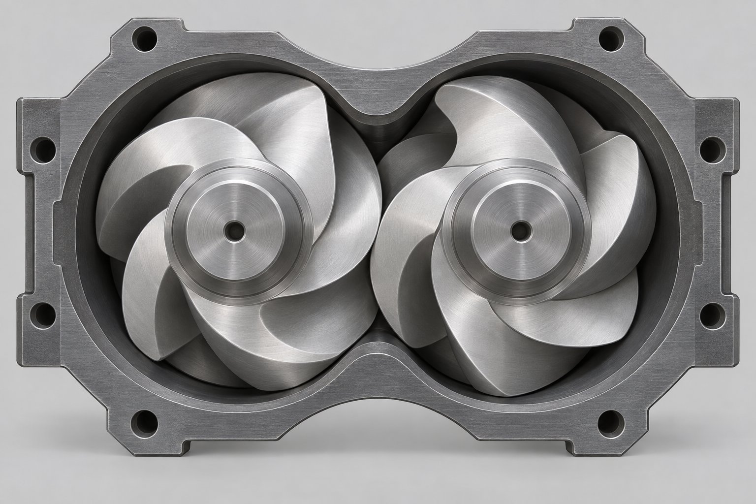
When you look at a cross-section of a co-rotating twin screw extruder, the two screw profiles are not identical circles with flights bolted on. They are mathematically conjugated shapes — each one generated as the geometric envelope of the other — and this principle traces back to a 1957 patent by Rudolf Erdmenger. The Erdmenger profile defines the self-wiping screw element geometry used in virtually every modern co-rotating twin screw extruder.
Imagine one screw rotating clockwise. Its lobe-shaped cross-section sweeps through the barrel bore, and at every angular position, the mating screw's profile is the exact conjugate — the shape required to follow the first screw's contour with minimal clearance. As both screws turn in the same direction, the flight tip of one screw continuously wipes the root of the other. Material cannot stagnate in the intermeshing zone because it is physically scraped away with every revolution. This self-wiping action delivers two major advantages:
- No dead zones: Stagnant material leads to degradation, especially with heat-sensitive polymers. Fully intermeshing Erdmenger profiles eliminate pockets where resin can hang up and thermally degrade.
- High-speed capability: Because the screws clean each other, co-rotating machines can run at 300 to 1,200+ rpm without building up degraded residue. Higher speed translates directly to higher throughput, making this geometry dominant in compounding and reactive extrusion applications.
The Do/Di ratio in co-rotating systems typically ranges from 1.40 to 1.80. A higher ratio means deeper channels, greater free volume per revolution, and more room for material intake — but it also means a thinner screw core, which limits torque capacity. Modern co-rotating twin screw extruders have trended toward higher Do/Di ratios (1.55 to 1.80) to maximize specific throughput, enabled by metallurgical advances in shaft and element materials that allow higher torque density.
Conveying in a co-rotating intermeshing system works primarily through drag flow. The rotating flights grip material against the barrel wall and push it forward along the helical channel. This mechanism is pressure-dependent — output decreases as die resistance increases — which is why co-rotating extruders are typically operated in starve-fed mode with a loss-in-weight or volumetric feeder controlling throughput independently of screw speed.
Co-Rotating vs Counter-Rotating Geometry and Positive Displacement Behavior
Counter-rotating intermeshing screws work on an entirely different principle. The two screws turn in opposite directions — typically outward, meaning the tops of the screws move away from each other at the nip point. Because the flights of one screw penetrate the channels of the other, the material is enclosed in helically distorted C-shaped chambers that act as sealed pockets. These pockets carry material axially from feed to die in a manner closer to a positive displacement pump than a drag-flow device.
This positive displacement behavior gives counter-rotating machines a key advantage: output is largely independent of die pressure. Whether you run a thin-wall pipe die at modest back pressure or a complex window profile die generating high restriction, the volumetric output stays relatively stable. For PVC profile extrusion — where precise dimensional control demands consistent flow rate — this characteristic is invaluable.
The trade-off? The calender gap. Where the flight tip of one screw passes the root of the other, the gap is extremely small (often less than 1 mm), and both screw surfaces move in the same direction at the nip. This creates a squeeze-flow condition analogous to calendering rollers. Experimental pressure measurements by Demirci et al. on a 55 mm counter-rotating parallel twin screw extruder revealed that pressure differences across the calender gap ranged from 4.7 to 7.1 MPa, generating separating forces exceeding one metric ton over a 300 mm metering zone. These forces push the screws outward toward the barrel wall, causing characteristic wear patterns at the so-called "ten o'clock and two o'clock" positions.
Because calender gap pressures and separating forces increase with speed, closely intermeshing counter-rotating extruders are limited to relatively low rotational speeds — typically below 150 rpm for smaller machines and under 50 rpm for large-diameter production units. Running faster would generate separating forces large enough to bend the screws and cause the barrel to "eat itself," as industry veterans describe it. This speed limitation directly constrains throughput compared to co-rotating systems.
Counter-rotating geometry also differs in its Do/Di ratio. Because the screws must resist bending under calender-gap forces, counter-rotating designs often use lower Do/Di ratios (1.40 to 1.55) to maintain a thicker, stiffer screw core. The conical twin screw extruder takes this principle further: the screws taper from a large diameter at the feed end to a smaller diameter at the discharge, which increases the root diameter-to-outer diameter ratio along the length and provides a stiffer shaft geometry while still allowing a large feed opening for bulk powder intake. Many PVC pipe and profile lines use conical twin screw extruder configurations precisely because the tapered geometry manages calender-gap forces more effectively than a constant-diameter parallel design.
Fully vs Partially Intermeshing Screw Profiles
The discussion so far has focused on closely or fully intermeshing screws — where the flight of one screw penetrates deeply into the channel of the other, leaving only a small mechanical clearance. This is the dominant design for both co-rotating compounding and counter-rotating profile extrusion. But partially intermeshing configurations exist too, and they solve specific problems that full intermeshing cannot.
In a partially intermeshing design, the centerline distance between the two screws is increased so that the flights overlap only partway into the opposing channel. The result is a wider gap between screws, which produces several effects:
- Reduced self-wiping: With a larger inter-screw gap, material can accumulate in the intermeshing zone. Self-cleaning is compromised, which limits suitability for materials prone to thermal degradation.
- Lower shear in the intermeshing region: The wider gap reduces the intense shear peaks that full intermeshing generates at the calender gap (counter-rotating) or at the wiping zone (co-rotating). This can be beneficial for extremely shear-sensitive materials.
- Increased mixing volume: The open intermeshing region acts as an additional mixing chamber, which can improve distributive blending for certain applications like rubber compounding or adhesive processing.
- Reduced separating forces: For counter-rotating machines, partial intermeshing dramatically cuts the calender-gap pressure and separating forces, allowing higher screw speeds. The trade-off is a loss of positive displacement pumping — the C-shaped chambers are no longer sealed, so output becomes more pressure-dependent.
A third category — non-intermeshing (also called tangential) — positions the screws side by side with no flight overlap at all. These are rare in polymer processing but appear in specialized rubber and adhesive applications where very high free volume and gentle mixing are prioritized over self-cleaning or positive displacement.
When evaluating co rotating and counter rotating twin screw extruder options for your application, the intermeshing degree is a critical — and often overlooked — specification. A fully intermeshing co-rotating twin screw extruder excels at high-speed compounding with excellent self-cleaning. A fully intermeshing counter-rotating parallel twin screw extruder delivers pressure-stable output for profile and pipe extrusion. A partially intermeshing variant trades some of those strengths for gentler shear or higher speed tolerance. The table below summarizes these distinctions at the screw element level.
| Characteristic | Co-Rotating Fully Intermeshing | Counter-Rotating Fully Intermeshing | Partially Intermeshing (Either Direction) |
|---|---|---|---|
| Profile Type | Erdmenger conjugated profiles | Matched flight-into-channel profiles forming C-shaped chambers | Reduced overlap profiles with enlarged inter-screw gap |
| Self-Wiping Capability | Excellent — continuous mutual wiping eliminates dead zones | Limited — flights wipe channels but calender gap creates stagnation risk | Poor — wider gaps allow material accumulation in intermeshing zone |
| Typical Do/Di Ratio | 1.55 to 1.80 | 1.40 to 1.55 (parallel); tapered in conical designs | Varies widely; typically similar to base configuration with increased center distance |
| Shear Distribution | Relatively uniform across channel; peaks at flight tip and intermeshing zone | High shear concentrated at calender gap; lower in C-chambers | More uniform but lower peak shear; reduced intensity in intermeshing region |
| Conveying Mechanism | Drag flow (pressure-dependent output) | Positive displacement via sealed C-chambers (pressure-independent output) | Hybrid — partially drag flow, partially positive displacement depending on overlap |
| Typical Max Screw Speed | 300 to 1,200+ rpm | <50 rpm (large) to ~150 rpm (small diameter) | Higher than fully intermeshing counter-rotating; lower than co-rotating |
| Primary Applications | Polymer compounding, masterbatch, reactive extrusion, devolatilization | PVC pipe and profile extrusion, sheet extrusion | Rubber compounding, adhesives, specialty low-shear blending |
Notice how every row in this comparison traces back to the cross-sectional geometry of the screw elements themselves — the Erdmenger conjugation, the C-chamber sealing, or the inter-screw gap width. Machine-level choices like gearbox torque and barrel heating are important, but the screw element geometry is where the fundamental processing physics originates.
What this comparison does not reveal is how these elements interact with each other when assembled into a complete screw profile. A co-rotating machine with the wrong element sequence produces mediocre results despite having superior self-wiping geometry. A counter-rotating extruder with a well-tuned element arrangement can outperform a poorly configured co-rotating line on certain products. The real performance differentiator is not just the type of elements or the rotation direction — it is the system-level architecture of how those elements are arranged zone by zone from feed to die.
Building a Twin Screw Extruder Screw Profile as an Integrated System
Knowing every element type, stagger angle, and disc width in the catalog is not the same as knowing how to build a screw profile that actually works. A 60-degree kneading block does not perform the same way whether it sits immediately after the feed throat or three barrel sections downstream of a fully molten zone. A reverse element placed too close to a vent port may seal beautifully — or it may overpressurize and blow melt out of the vacuum opening. The reason is straightforward: in a twin screw extruder machine, every element inherits the conditions created by whatever sits upstream and simultaneously shapes the conditions for everything downstream. Sequence is not a secondary detail. It is the design itself.
Think of it this way. Each element receives material in a specific state — a certain fill level, melt fraction, temperature, and pressure — and hands it off in an altered state. A high-pitch conveying element in the feed zone delivers loosely packed pellets with zero melt fraction and near-atmospheric pressure. A kneading block two zones later receives partially molten polymer at elevated temperature with moderate fill. The same kneading block would behave entirely differently if placed earlier, when solids still dominate, or later, when the melt is fully homogeneous. That element-to-element dependency is what makes screw configuration a system-level discipline rather than a parts list exercise.
Zone-by-Zone Screw Profile Architecture
A typical screw profile on a co-rotating double screw extruder machine can be divided into five to six functional zones, each defined by its element combination and process objective. Walking through them in sequence reveals how the material transforms from raw feedstock to pressurized melt ready for the die.
- Feed and Solids Conveying Zone — This is where material enters the extruder system through the feed throat. Deep-flight, high-pitch conveying elements (typically 1.5D to 2D pitch) dominate this section. Their job is simple: grab pellets, powder, or flakes and transport them forward as quickly as possible. Fill level here is deliberately kept low — most twin screw extruder machines operate in starve-fed mode, meaning the feeder, not the screw, controls throughput. The wide-open channel geometry prevents bridging at the extruder feed barrel opening, and the rapid forward transport keeps material from backing up into the hopper. No kneading blocks or restrictive elements belong in this zone. Any back pressure here chokes feed intake and destabilizes the entire process downstream.
- Melting and Plastication Zone — As material advances, it encounters barrel sections heated to target temperatures and begins transitioning from solid to melt. This zone typically uses a combination of progressively tighter-pitch conveying elements followed by kneading blocks with increasing stagger angles — often starting at 30 degrees and stepping up to 45 or 60 degrees. The graduated approach matters. Placing intense dispersive mixing elements too early, when material is not fully molten, leads to unmelted particles, unstable pressure, and potential torque spikes. Instead, mild kneading blocks initiate softening and partial melting, while more aggressive blocks downstream complete the phase change once enough melt exists to transmit shear effectively. By the exit of this zone, the material should be substantially or fully molten.
- Primary Mixing Zone — With the polymer now in a molten state, this zone applies the main mixing work. Kneading blocks and specialized mixing elements — toothed mixing elements for distributive action, wide-disc kneading blocks for dispersive deagglomeration — are concentrated here. The specific configuration depends on what the formulation demands. A pigment masterbatch might require high-stagger kneading blocks to break down agglomerated colorants. An unfilled polymer blend might need gentler distributive elements that split and recombine flow streams without generating excessive shear. Side feeders for downstream addition of fillers or glass fibers often connect at the transition between the melting zone and the primary mixing zone, where the melt is hot enough to wet-out additives but the profile still has enough mixing length ahead to achieve homogeneity.
- Devolatilization and Venting Zone — Many compounding and reactive extrusion processes require removal of moisture, residual monomers, or solvents. This zone pairs deep-flight, high-pitch conveying elements under an open or vacuum-connected barrel section. The deep channels reduce fill level and expose maximum melt surface area to the low-pressure environment, allowing volatiles to escape. Critically, a melt seal must exist upstream of this zone — typically created by a reverse element, reverse kneading block, or blister ring — to prevent atmospheric air from being drawn backward through the barrel. A second seal downstream of the vent prevents melt from being sucked out through the vacuum port. The balance between seal restriction and vent-zone openness determines degassing efficiency; too tight a seal raises temperature, while too loose a seal allows gas bypass.
- Secondary Mixing and Homogenization Zone (optional) — Some profiles include an additional mixing section downstream of venting to finalize composition uniformity. This zone typically uses milder elements — low-stagger kneading blocks, toothed mixing elements, or slotted screw mixing elements — because the material has already been through the primary mixing stage and excessive additional shear would raise melt temperature beyond acceptable limits. This zone is common in color-critical masterbatch production and reactive extrusion where final additive incorporation occurs after devolatilization.
- Metering and Pressure Build-Up Zone — The final section of the screw profile uses tight-pitch conveying elements (0.5D to 1D pitch) to compress and pressurize the melt. Consistent pressure at the die face is essential for dimensional stability of pellets, strands, film, or profiles. If upstream zones generate pressure fluctuations — from inconsistent melting, uneven fill, or surging — the metering zone must be long enough to dampen them. Insufficient metering length results in pulsating output, uneven strand thickness, and die drool. This is also where the full barrel length matters: a longer L/D ratio gives you the room to build adequate metering length without stealing zones from mixing or venting upstream.
Notice the underlying logic. Each zone transitions the material from one state to the next: loose solid to compressed solid, compressed solid to partial melt, partial melt to fully molten and mixed, molten melt to degassed melt, and degassed melt to pressurized output. Skip a transition — place a kneading block where solids have not yet softened, or attempt devolatilization before creating a melt seal — and the entire downstream profile underperforms.
How Screw Configuration Drives Specific Mechanical Energy and Melt Temperature
Two numbers dominate process optimization conversations around any twin-screw extruder machine: specific mechanical energy (SME) and melt temperature at the die. Both are direct consequences of screw element selection and arrangement — and both involve trade-offs that cannot be resolved by adjusting barrel heaters alone.
Specific mechanical energy is the amount of mechanical work the screws deliver per unit mass of material, typically expressed in kWh/kg or kJ/kg. It is calculated from measured torque, screw speed, and throughput. Every restrictive element in the profile — kneading blocks, reverse elements, blister rings — converts motor torque into viscous dissipation inside the melt. More restrictive elements or higher stagger angles raise SME. Removing a kneading section or replacing a 90-degree block with a 45-degree block drops it.
Why does SME matter? Because it quantifies how much mechanical transformation the material receives as opposed to thermal input from barrel heaters. For many compounding operations, achieving a target SME range correlates directly with product quality metrics like pigment dispersion, filler distribution, and degree of polymer blending. Too little SME means under-mixed product. Too much means over-worked polymer — degraded molecular weight, discolored resin, or broken reinforcing fibers.
Melt temperature is coupled to SME but not identical. A portion of the mechanical energy input converts to heat through viscous shear, raising the melt temperature above the barrel set-point. This viscous dissipation effect intensifies wherever shear rates are highest — at kneading block tips, inside narrow calender gaps, and across reverse element restrictions. Overloading the screw with high-stagger kneading blocks is one of the most common design mistakes: it drives both torque and melt temperature beyond useful limits without corresponding quality gains.
The interplay between element selection, screw speed, and throughput adds another dimension. Increasing screw speed at constant throughput raises the shear rate across every element in the profile, which increases both SME and melt temperature. Increasing throughput at constant screw speed has the opposite effect — fill level rises, but the energy input per kilogram drops because the same motor work is spread across more material. Experienced process engineers use this speed-to-throughput ratio as a tuning lever: if melt temperature is too high but mixing quality is acceptable, increasing feed rate relative to screw speed can bring temperature back into range without changing a single element on the shaft.
Fill level distribution along the barrel also matters. In starve-fed twin screw operation, many zones operate partially filled, which limits the shear that elements can actually impart. Only fully filled zones — typically just upstream of restrictive elements and in the metering section — experience the maximum shear and energy input that the element geometry is capable of generating. This means two profiles with identical element sequences can produce different SME values simply because their feed rates create different fill distributions. Pressure sensors placed along the barrel confirm these filled zones: a spike in local pressure indicates a fully filled region where the elements are doing their most intensive work.
Ultimately, screw configuration, operating parameters, and material rheology form a three-way interaction. The profile sets the potential for energy input and mixing at each zone. Screw speed and feed rate determine how much of that potential is realized. And the material's viscosity, thermal sensitivity, and filler loading dictate how it responds to the conditions imposed. Adjusting any one of these three factors without considering the other two is why many operators experience frustrating trial-and-error cycles.
What this system-level perspective also reveals is a vulnerability: as screw elements wear — flight tips round off, tip clearance increases, kneading disc edges erode — the carefully tuned energy and pressure profile degrades zone by zone. The screw may look the same on the shaft, but its functional geometry has quietly shifted. Recognizing when and where that degradation reaches a critical threshold is the next essential layer of twin screw extruder screw management.
Screw Element Wear Mechanisms and Maintenance Strategies
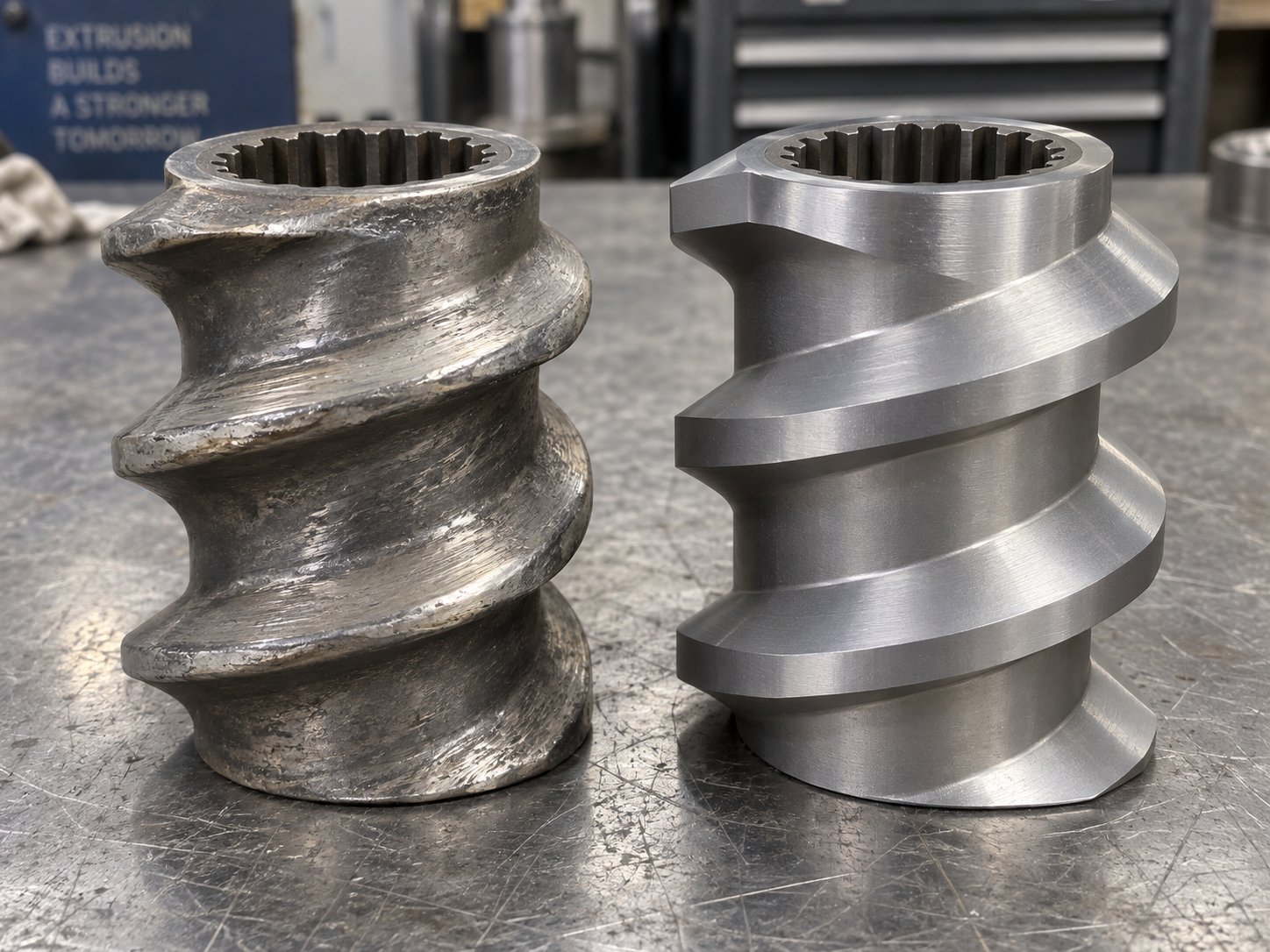
A perfectly configured screw profile does not stay perfect. Every revolution grinds flight tips against abrasive fillers, every thermal cycle stresses metal surfaces, and every corrosive additive slowly eats into element geometry. The result? That carefully tuned energy and pressure distribution you built zone by zone quietly deteriorates — tip clearances widen, kneading disc edges round off, and mixing performance drifts downward long before anything catastrophic happens. Understanding how screw elements wear, when to inspect them, and what materials resist degradation is the difference between proactive maintenance and a surprise shutdown that costs tens of thousands.
One of the most persistent durable twin screw systems challenges is that wear is invisible during operation. You cannot see inside a closed barrel extruder while it runs. By the time throughput drops measurably or product quality slips, the damage has often progressed well beyond optimal replacement thresholds. A disciplined inspection program — anchored to dimensional limits rather than guesswork — catches degradation early and keeps your twin screw and barrel operating within design tolerance.
Three Wear Mechanisms That Degrade Screw Elements
Not all wear looks the same, and not all wear has the same root cause. Three distinct mechanisms attack screw elements and barrel liners in twin screw extruders, each leaving characteristic signatures that guide your maintenance response.
- Abrasive wear: This is the most common form of degradation in compounding operations. Hard particles — calcium carbonate, glass fiber, titanium dioxide, mineral fillers — act like fine sandpaper against flight tips, kneading disc edges, and barrel walls. The sharp machined corners of a new plastic extruder screw gradually become rounded, smooth, and occasionally polished. Abrasive wear is volume-dependent rather than time-dependent: it correlates with how much material you process, not how many hours the machine has been running. Highly filled compounds at high throughputs accelerate it dramatically. Kneading blocks and reverse elements in mixing zones suffer the worst abrasion because fill levels and shear stresses are highest there.
- Adhesive wear: This occurs when metal-to-metal contact happens between screw elements and the barrel wall, or between the two intermeshing screws themselves. You will see it manifest as flattened flight tips, score marks on the barrel bore, and scratches on the flanks and roots of screw flights. The root cause is usually insufficient support of the screw shafts within the barrel. During normal production, molten resin acts as a hydrodynamic bearing film that prevents direct metal contact. When screws rotate at high speed without material — between production runs, during purging, or at startup — that lubrication film disappears and the shafts deflect into the barrel or into each other. Automated shutdown protocols that reduce screw speed when torque drops below a threshold are the primary countermeasure.
- Corrosive wear: Chemical attack from reactive processing materials degrades the metal surface of screw elements and the extruder screw barrel lining. The telltale sign is a dimpled or pitted surface rather than the smooth rounding you see with abrasion. Corrosive wear is less common in standard polymer compounding but becomes significant when processing flame-retardant compounds that release acidic gases, halogenated polymers, or any formulation that generates condensation on chilled barrel sections. It attacks all element surfaces but is most damaging where fresh surface is continuously exposed — at high-shear zones where protective oxide layers are stripped away by simultaneous abrasive action.
In practice, these mechanisms rarely act alone. A glass-fiber-filled engineering plastic abrades flight tips while the coupling agent in the formulation may introduce mild corrosive attack. Recognizing which mechanism dominates your specific process dictates whether you need harder element materials, corrosion-resistant alloys, or simply better operational protocols to prevent dry running.
Inspection Criteria and Replacement Scheduling
How do you know when an element has crossed the line from "worn but functional" to "degrading your process"? You measure — and you measure on a fixed schedule, not when something goes wrong.
A practical inspection cadence for most compounding and masterbatch operations looks like this: visual inspection of accessible elements monthly, dimensional measurement quarterly, and a full screw pull with element-by-element assessment every 2,000 to 3,000 operating hours or at each major product changeover. Plants running highly abrasive formulations — glass-fiber-reinforced compounds, mineral-filled masterbatch, recycled feedstock with contaminants — should shorten these intervals.
When you pull the screws, here is what to look for and what the numbers mean:
| Inspection Point | What to Measure | Replacement Threshold | Impact of Ignoring |
|---|---|---|---|
| Flight tip OD | Outer diameter reduction from original spec | ~5% off starting diameter over three-quarters of element length | Increased tip clearance causes leakage flow, reduced conveying efficiency, and degraded mixing |
| Screw-to-barrel gap | Radial clearance between flight tip and barrel bore | Greater than 0.8 mm (from typical new clearance of 0.15–0.30 mm) | Backflow increases, throughput drops, residence time rises — risking thermal degradation |
| Screw edge wear | Material loss at leading and trailing flight edges | Edge wear exceeding 0.5 mm | Reduced self-wiping; material hangs up and degrades in dead zones |
| Kneading disc edges | Visual rounding and dimensional loss at disc tips and transitions | Visible rounding; nicks, gouges, or any hairline cracks | Mixing intensity drops; cracked discs risk shaft twisting and barrel damage |
| Barrel bore ID | Internal diameter increase from original spec | ~5% increase in starting diameter over a length of 1D | Barrel-side clearance compounds screw wear effects; both must be assessed together |
One critical rule: discard any element with a hairline crack immediately. A cracked kneading disc or conveying element under torque can fracture, twist the splined shaft, damage adjacent elements, and gouge the barrel bore — turning a modest replacement cost into a catastrophic repair bill. Smooth minor surface nicks with a fine file, but never run a cracked element.
What makes wear data truly powerful is trending. Recording OD measurements for each element position at every inspection lets you plot wear rate over time. You will quickly see which zones degrade fastest — almost always the primary mixing zone and any zone processing abrasive fillers — and can stock replacement elements proactively for those positions rather than waiting for a failure-driven discovery.
Material Selection for Wear Resistance
Choosing the right element material is your most effective defense against all three wear mechanisms. Not every application needs the most expensive alloy — but running standard nitrided steel in a barrel extruder processing 40% glass-fiber-filled nylon will burn through elements at a rate that dwarfs the cost difference of upgrading.
Here is how the major material categories map to wear types and application demands:
- Nitrided steel (e.g., 38CrMoAlA): The baseline material for many standard compounding operations. Gas nitriding creates a hard surface layer that resists moderate abrasion and provides acceptable service life for unfilled or lightly filled polymers. Cost-effective and widely available, but insufficient for heavily filled or corrosive formulations.
- Tool steel and high-speed steel (HSS): Higher carbon content and alloying elements like chromium, tungsten, and vanadium deliver significantly greater hardness and hot-hardness retention. Quenched and tempered tool steels are a step up for moderately abrasive compounds — think calcium-carbonate-filled polyolefins or talc-filled polypropylene — where nitrided steel wears too quickly but premium alloys are not cost-justified.
- Powder metallurgy HIP alloys (PM-HIP): Manufactured through hot isostatic pressing, these alloys achieve an extremely uniform carbide distribution that conventional cast or wrought steels cannot match. The result is substantially higher abrasion resistance with consistent performance across the entire element surface. PM-HIP elements are the standard choice for glass-fiber-reinforced compounds, mineral-filled masterbatch, and any formulation where abrasive wear is the dominant failure mode.
- High-wear-resistance HIP alloys (e.g., CPM 10V, CPM 15V): These ultra-premium alloys incorporate extremely high levels of vanadium and tungsten during the powder metallurgy process, forming dense networks of hard vanadium carbide particles. Their wear resistance can be several times that of conventional high-speed steel, making them suitable for the most demanding applications — highly filled engineering plastics, recycled feedstocks contaminated with metal particles, or continuous 24/7 production where element longevity directly impacts line economics.
- Corrosion-resistant alloys (nickel-based): When processing halogenated polymers, flame-retardant compounds, or any chemistry that generates acidic byproducts, corrosion resistance trumps abrasion resistance. Nickel-chromium-molybdenum alloys form a stable passivation layer that resists chemical attack even at elevated processing temperatures.
- Surface treatments and coatings: HVOF (high-velocity oxygen fuel) sprayed coatings and bimetallic cladding add a high-performance wear layer to a tougher, less expensive substrate. This approach can deliver PM-HIP-level surface performance at reduced cost, though coating adhesion and layer thickness must be carefully controlled to prevent delamination under high torque loads.
Matching element material to your specific process conditions — filler type, loading level, processing temperature, and production volume — is ultimately an economic optimization. A plastic extruder screw running unfilled polypropylene pelletizing does not need PM-HIP elements. A twin screw compounding line running 60% calcium carbonate filler around the clock absolutely does. The upfront cost of premium materials pays back quickly when replacement intervals extend from weeks to months.
When it comes to sourcing modular replacement segments and kneading blocks for your maintenance program, material quality and dimensional precision are non-negotiable. Elements that do not hold tight tolerances out of the box defeat the purpose of a scheduled replacement. NANHAIYA's segment screw and twin screw elements are designed for drop-in compatibility across compounding, recycling, masterbatch, and pelletizing operations — the exact applications where wear-driven replacement is a recurring operational reality. Having a reliable supply chain for quality modular segments means you can execute replacements on your maintenance schedule rather than waiting on lead times that extend unplanned downtime.
Preventing wear and replacing worn elements keeps your screw profile functional. But what about the situations where the profile itself is the problem — when mixing quality is poor, melt temperature is too high, or the extruder keeps tripping on torque overload despite healthy element dimensions? Those are screw design problems, not maintenance problems, and they demand a different set of solutions.
Troubleshooting Processing Problems With Screw Design Fixes
Your elements pass dimensional inspection. Barrel liners are within tolerance. Heaters and thermocouples check out fine. Yet the product is still coming off with visible unmixed filler streaks, the melt temperature keeps climbing past spec, or the drive trips on torque every third run. Sound familiar? These are not maintenance problems — they are screw configuration problems, and they require element-level solutions rather than wrench-level fixes.
The challenge is that processing symptoms in a polymer extruder often point in multiple directions simultaneously. A torque overload could stem from an overly restrictive kneading section, a heater failure, or an overfed barrel. Adam Dreiblatt of CPM Century Extrusion draws a useful analogy: diagnosing compounding problems is like diagnosing illness — you first determine whether the issue is chronic (present every time a formulation runs) or transient (appearing suddenly in a previously stable process). Chronic problems that repeat identically across every lot strongly suggest that the screw profile or die design itself is the root cause, not a worn part or a bad batch of resin. For these chronic issues, the only real cure is redesigning the screw configuration.
The troubleshooting matrix below maps the most common chronic symptoms directly to their screw element root causes and actionable fixes. Use it as a diagnostic starting point before pulling screws and rearranging elements.
| Symptom | Root Cause | Screw Element Adjustment | Expected Outcome |
|---|---|---|---|
| Poor mixing homogeneity — visible filler streaks, uneven color, undispersed pigment agglomerates | Insufficient mixing intensity or too few mixing zones in the profile | Increase kneading block stagger angles (swap 30° for 45° or 60°); add narrow-disc kneading blocks for distributive action; insert toothed mixing elements (ZME/TME) downstream of primary mixing zone | Improved spatial distribution of additives and complete deagglomeration; uniform color and mechanical properties across pellets |
| Excessive melt temperature at die — polymer degradation, discoloration, reduced molecular weight | Too many high-shear elements concentrated in a short zone; excessive dispersive mixing beyond what the formulation requires | Replace high-stagger kneading blocks (60°–90°) with lower-stagger blocks (30°–45°); increase conveying element pitch between kneading sections to allow cooling; shorten total kneading block length | Lower viscous dissipation per zone; melt temperature drops toward barrel set-point; reduced thermal degradation and improved product clarity or color |
| Torque overload — motor trips or runs near maximum amperage continuously | Energy input concentrated at too few restrictive elements; excessive back pressure from reverse elements or long neutral kneading blocks | Redistribute mixing across multiple shorter kneading sections separated by conveying elements; reduce or shorten reverse elements; replace neutral 90° blocks with forward-pumping 45° or 60° blocks | Motor load drops as energy input spreads over a longer barrel length; process runs within safe torque margin while maintaining adequate mixing |
| Insufficient devolatilization — porous pellets, residual moisture above spec, bubbling strands | Inadequate melt seal upstream of vacuum port; insufficient melt surface renewal in the vent zone | Add or lengthen reverse conveying element or blister ring upstream of the vent barrel; replace standard-pitch elements under the vent opening with deep-flight, high-pitch elements to maximize exposed melt surface | Stronger pressure seal prevents air bypass; increased free volume under the vent improves volatile escape; residual moisture and monomer content drops to specification |
| Poor feeding and bridging — inconsistent intake, surging throughput, hopper blockage | Insufficient free volume at the feed zone; back pressure from downstream elements pushing material toward the feed throat | Install maximum-pitch conveying elements (1.5D–2D) at the feed zone; ensure no restrictive elements exist within first two barrel sections; lengthen the conveying section before the first kneading block | Material clears the feed throat rapidly; fill level stays low and stable; downstream torque and pressure fluctuations reduce as feed becomes consistent |
Solving Poor Mixing and Dispersion Through Element Adjustment
When pellets come off the screw extruder granulator with visible streaks, white specs in a colored compound, or inconsistent ash content sample to sample, the instinct is to crank up screw speed. More rpm means more shear, which should mean better mixing — right? Not necessarily. Higher speed without a profile change often just raises melt temperature and throughput simultaneously, leaving the shear-per-unit-mass largely unchanged while pushing the polymer closer to its degradation threshold.
The more effective approach targets element geometry directly. Distributive mixing relies on repeatedly splitting, stretching, folding, and recombining the melt — and that requires enough mixing elements in the profile to create those flow rearrangements. If your profile uses only two or three kneading blocks in the entire mixing zone, simply adding one or two more blocks with appropriate stagger angles creates additional fold-and-recombine cycles that dramatically improve homogeneity.
For dispersive challenges — hard pigment agglomerates that survive the mixing zone intact — the fix is more targeted. Narrow-disc kneading blocks at higher stagger angles (60° forward) generate the localized pressure fluctuations and extensional flow needed to fracture cohesive clusters. Placing a short reverse kneading block at the end of the mixing section forces material to recirculate through the high-shear zone multiple times, ensuring even the most stubborn agglomerates encounter stress peaks above their cohesive strength. The trade-off is a predictable uptick in melt temperature, so monitor die-exit temperature closely after any dispersive element addition.
For an extruder for polymer blending where the two components have similar viscosities and no hard agglomerates are present, distributive elements are the better investment. Toothed mixing elements and low-stagger kneading blocks generate the repeated flow splitting that achieves spatial uniformity without the thermal penalty of aggressive dispersive blocks.
Reducing Melt Temperature and Torque Overload
Excessive melt temperature and torque overload are two faces of the same underlying issue: too much mechanical energy concentrated in too few zones. They often appear together because the same restrictive elements that spike torque also generate the highest viscous dissipation — and thus the steepest local temperature rise.
Screw element wear-out can amplify torque problems over time as degraded elements lose conveying efficiency and material backs up against restrictive zones. But when the problem is chronic from day one — identical overload on every run of a given formulation — the profile design itself needs revision.
The fix follows a straightforward principle: spread the work. Instead of concentrating all kneading blocks in a single 4D-long mixing zone, break them into two or three shorter sections separated by conveying elements. Each conveying section allows the melt to cool slightly against the barrel wall and reduces the cumulative pressure spike that the motor must overcome. Replace any neutral or reverse kneading blocks that are not strictly necessary for melt sealing with forward-staggered alternatives that contribute mixing work while still pumping material downstream.
On a hot melt extruder processing pressure-sensitive adhesives or thermoplastic elastomers — materials notoriously sensitive to shear-induced overheating — this distributed approach is not optional. Concentrating mixing energy in one aggressive zone can push melt temperature 30 to 50 degrees above barrel set-point through viscous dissipation alone. Distributing that same total mixing work across three gentler zones, each followed by a cooling conveying section, can hold melt temperature within 10 to 15 degrees of the set-point while achieving equivalent mixing quality.
The speed-to-throughput ratio offers an additional lever that does not require pulling the screw. Increasing feed rate at constant screw speed spreads the same motor energy across more material, reducing specific mechanical energy input per kilogram. If torque is near maximum but mixing is already adequate, raising throughput slightly can bring the process back within safe operating margin. Conversely, if quality demands a fixed throughput, reducing screw speed lowers the energy input at every element — though this also reduces mixing intensity, so the profile may need compensating adjustments.
Improving Devolatilization and Feed Zone Performance
Devolatilization failures and feed zone instability sit at opposite ends of the barrel, but they share a common thread: both involve getting material into or out of the screw profile at controlled rates, and both are critically sensitive to element selection in their respective zones.
Porous pellets, bubbling strands, and out-of-spec moisture levels after the die all point to inadequate volatile removal in the vent zone. The most frequent design error is an insufficient melt seal upstream of the vacuum port. Without a proper seal — created by a reverse conveying element, reverse kneading block, or blister ring — atmospheric air gets sucked backward through the barrel, breaking the vacuum and preventing volatiles from escaping the melt surface. Strengthening or lengthening the seal element upstream of the vent is usually the single highest-impact fix for poor degassing performance.
Equally important is the element geometry under the vent opening itself. Conveying elements around vent ports are used to reduce pressure so gases can escape, maintain a stable downstream melt seal, and provide enough surface renewal for volatiles to diffuse out. Deep-flight, high-pitch conveying elements reduce fill level and expose more melt surface area to the low-pressure vent environment. Replacing a standard 1D-pitch element under the vent with a 1.5D or 2D-pitch element can measurably improve degassing without any other profile changes.
At the opposite end, feed zone instability — surging intake, powder bridging in the hopper throat, and erratic torque swings — almost always traces to insufficient open volume at the screw entry. If conveying elements under the feed opening are too short-pitched or if a kneading block sits too close to the feed zone, material cannot clear the throat fast enough. Buildup of powder in feed hoppers can eventually avalanche into the extruder, causing torque spikes that appear random but actually correlate with humidity and powder characteristics. The fix is mechanical and configurational: maximize conveying element pitch (2D) across the first two barrel sections, ensure no restrictive elements exist within the initial feed zone, and verify that the starve-feed strategy keeps the screw channel well below full capacity at the entry point.
Each of these troubleshooting scenarios circles back to the same core idea: the twin screw extruder screw profile is a system where every element affects every other element. Fixing a symptom in one zone often requires understanding — and sometimes adjusting — elements two or three zones away. With a clear diagnostic framework and the confidence to make targeted element swaps, most chronic processing problems resolve into predictable, repeatable solutions. The remaining question is how to match those element choices to specific applications and where to source quality segments when your maintenance or optimization program demands them.
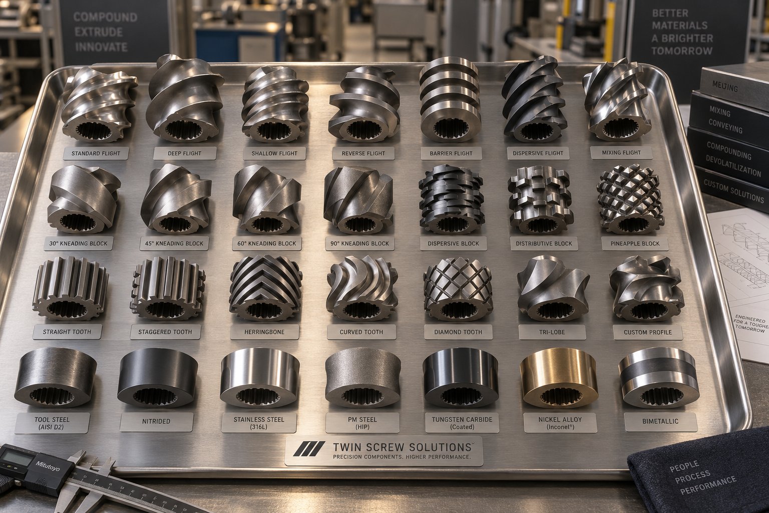
Selecting and Sourcing the Right Screw Elements for Your Process
Diagnosing a screw profile problem is one thing. Choosing the right replacement elements — ones matched to your specific material, application, and production goals — is where that diagnostic knowledge converts into real-world results. A compounding line running glass-fiber-reinforced nylon and a masterbatch operation dispersing organic pigments into polyethylene both use twin screw extruder screws, but they demand radically different element priorities. Selecting elements without considering this context is like prescribing medicine without a diagnosis.
Matching Screw Elements to Application Requirements
Your material type is the single strongest driver of element selection. Unfilled polymers are forgiving — standard nitrided steel elements with moderate kneading sections handle them well. Highly filled compounds demand wear-resistant alloys and carefully staged mixing. Recycled feedstock introduces variability that requires gentle, flexible configurations. Color masterbatch prioritizes dispersion above almost everything else.
The table below maps four major application categories to their recommended element configurations, priorities, and key performance considerations. Notice how modular segment screws appear as the foundational advantage across all four — their reconfigurability lets you adapt to formulation changes without purchasing entirely new screw assemblies.
| Application | Recommended Element Configuration | Key Element Priorities | Critical Performance Considerations |
|---|---|---|---|
| Compounding (filled engineering plastics, polymer blends) | High-pitch feed elements; staged kneading blocks (30° to 60° progressive stagger); reverse element melt seals for devolatilization; tight-pitch metering zone | PM-HIP or high-wear alloy elements for abrasive fillers; sufficient mixing length for complete dispersion; robust melt sealing upstream of vent ports | Balance between mixing intensity and melt temperature; torque management across multiple kneading zones; fiber length preservation in glass-filled grades |
| Recycling (post-consumer, post-industrial regrind) | Extended high-pitch feed zone for inconsistent bulk density; moderate kneading with lower stagger angles (30°–45°); deep-flight devolatilization section with strong vacuum seal | Gentle conveying to avoid torque spikes from contaminants; effective degassing for moisture and volatiles; corrosion-resistant alloys if processing mixed-stream or halogenated waste | Feedstock variability demands a forgiving profile; excessive shear degrades already-stressed polymer chains; contamination accelerates abrasive and corrosive wear simultaneously |
| Masterbatch (color concentrates, additive carriers) | Aggressive dispersive kneading (wide-disc, 60° blocks) in primary mixing zone; distributive elements (narrow-disc blocks, TME/ZME) downstream; short reverse blocks for recirculation through high-shear zones | Maximum pigment deagglomeration without exceeding carrier resin thermal limits; uniform spatial distribution validated by filter pressure testing | Color strength and consistency are the primary quality metrics; undispersed agglomerates cause customer rejects; melt temperature control is critical for heat-sensitive carriers |
| Pelletizing (strand, underwater, or water-ring cutting) | Emphasis on metering zone: long tight-pitch conveying section for stable die pressure; minimal mixing if material arrives pre-compounded; simple profile with limited kneading | Pressure stability at the die face; consistent strand diameter or pellet weight; element wear resistance matched to throughput volume | Pressure surging causes uneven pellet size and strand breakage; overly aggressive mixing raises melt temperature unnecessarily for already-homogeneous material |
Whether you are running a production-scale compounding line or a laboratory twin screw extruder for formulation development, the logic holds: match element type and material grade to the specific stresses your process imposes. A lab scale twin screw extruder testing a new glass-fiber compound at small volumes still needs wear-resistant kneading blocks in its mixing zone — abrasion does not care about machine size. Scaling from lab to production means preserving the element sequence ratios and material selections that worked at the small scale, not just multiplying barrel diameter.
When evaluating twin screw extruder manufacturers, pay close attention to whether their element catalog covers the full range of alloy grades, stagger angles, and pitch options discussed throughout this article. A twin-screw extruder manufacturer that only offers standard nitrided steel elements forces you into a one-size-fits-all compromise that limits process optimization.
Sourcing Quality Modular Screw Segments for Your Operation
Every insight in this article — from kneading block stagger angles to wear-driven replacement thresholds — ultimately depends on having access to precision-manufactured elements when you need them. Maintenance schedules slip when lead times stretch. Profile optimization stalls when the specific element configuration you want is not available from your supplier.
NANHAIYA's modular screw segments, screw elements, and kneading blocks are built to serve exactly the applications this article covers — compounding, recycling, masterbatch, and pelletizing. Their segment screw product line provides drop-in replacement elements across a range of alloy grades and geometric configurations, giving you the flexibility to reconfigure profiles for new formulations or replace worn zones without sourcing from multiple vendors. For operations where twin screw extruder screw performance directly determines product quality and uptime, having a dedicated element supplier with application-specific expertise shortens the path from diagnosis to solution.
Frequently Asked Questions About Twin Screw Extruder Screws
1. What is the difference between a screw shaft and screw elements in a twin screw extruder?
The screw shaft is a splined or keyed steel core that transmits torque from the gearbox, while screw elements are the functional segments that slide onto that shaft. Elements include conveying flights, kneading blocks, mixing discs, and sealing components. Together, the shaft and its assembled elements form the complete twin screw extruder screw. This modular design allows processors to disassemble, rearrange, and rebuild profiles to match different formulations or process objectives without replacing the entire screw assembly.
2. How does kneading block stagger angle affect mixing performance?
Stagger angle directly controls mixing intensity, forward conveying action, and melt temperature rise. A 30-degree forward stagger provides gentle mixing with strong conveying, behaving almost like a transport element. At 45 to 60 degrees, forward pumping weakens while dispersive shear increases significantly — ideal for melting crystalline polymers and breaking down filler agglomerates. A 90-degree neutral stagger eliminates net conveying entirely, maximizing residence time and distributive mixing. Reverse-staggered blocks push material backward, generating the most intense shear and highest melt temperature of any kneading configuration. Effective screw profiles typically sequence multiple stagger angles progressively rather than relying on a single angle.
3. When should I replace worn twin screw extruder screw elements?
Replace screw elements when the outer diameter has decreased by approximately 5% from the original specification over three-quarters of the element length, or when the screw-to-barrel radial clearance exceeds 0.8 mm (from a typical new clearance of 0.15 to 0.30 mm). Kneading discs showing visible edge rounding, nicks, or any hairline cracks should be discarded immediately — cracked elements under torque can fracture and cause catastrophic barrel and shaft damage. Establishing a quarterly dimensional measurement schedule and trending wear data by element position allows you to predict replacement needs proactively. Suppliers like NANHAIYA (nhyscrews.com) offer modular segment screws and kneading blocks for drop-in replacement across compounding, recycling, masterbatch, and pelletizing applications.
4. What is the Do/Di ratio and why does it matter for twin screw extruder performance?
The Do/Di ratio is the outer diameter (flight tip) divided by the inner diameter (channel root) of a screw element. It typically ranges from 1.40 to 1.80 in co-rotating twin screw extruders. A higher Do/Di ratio creates deeper channels with greater free volume per revolution, which increases material intake capacity and specific throughput. However, deeper channels also mean a thinner screw core, which limits maximum torque capacity. Modern extruders trend toward ratios of 1.55 to 1.80, enabled by advanced shaft metallurgy that supports higher torque density. Counter-rotating designs generally use lower ratios (1.40 to 1.55) to maintain stiffer shafts that resist bending under calender-gap separating forces.
5. How do I fix excessive melt temperature caused by my twin screw extruder screw profile?
Excessive melt temperature usually results from too much mechanical energy concentrated in too few mixing zones. The most effective fix is to redistribute mixing work: break a single long kneading block section into two or three shorter sections separated by conveying elements, which allow the melt to cool against the barrel wall between mixing bursts. Replace high-stagger kneading blocks (60 to 90 degrees) with lower-stagger alternatives (30 to 45 degrees) where full dispersive intensity is not required. Increasing feed rate at constant screw speed also helps by spreading the same motor energy across more material, reducing specific mechanical energy per kilogram. For shear-sensitive materials like TPEs or adhesives, this distributed mixing approach can hold melt temperature within 10 to 15 degrees of barrel set-point rather than 30 to 50 degrees above it.
Written by
Nanhaiya Technical Team
Zhoushan Nanhaiya Plastic Machinery Co., Ltd.
The Nanhaiya technical team supports screw and barrel manufacturing projects through application review, technical communication, custom manufacturing coordination, and production and quality control.
Discuss Your Application
Related Articles
More insights on screw barrel technology and plastics processing.
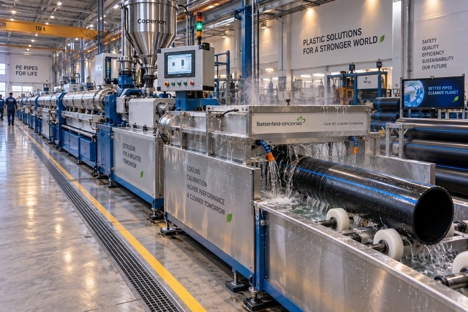
Plastic Pipe Extruder Decoded: Screw Design to Flawless Pipe
Oct 13, 2026
Learn how a plastic pipe extruder works — from screw and barrel design to material-specific processing, defect troubleshooting, and line sizing for PVC, HDPE, and PP-R pipe.
Read Article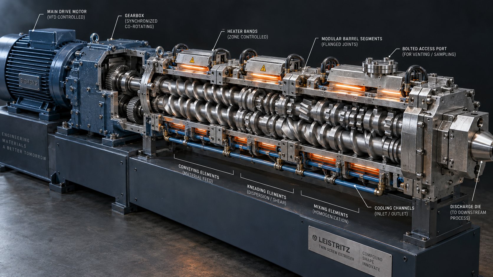
Co Rotating Twin Screw Extruder Parts: From Drive To Die Face
Oct 12, 2026
Complete guide to co rotating twin screw extruder parts — screw elements, kneading blocks, barrel segments, drive components, and material grades explained for sourcing and optimization.
Read Article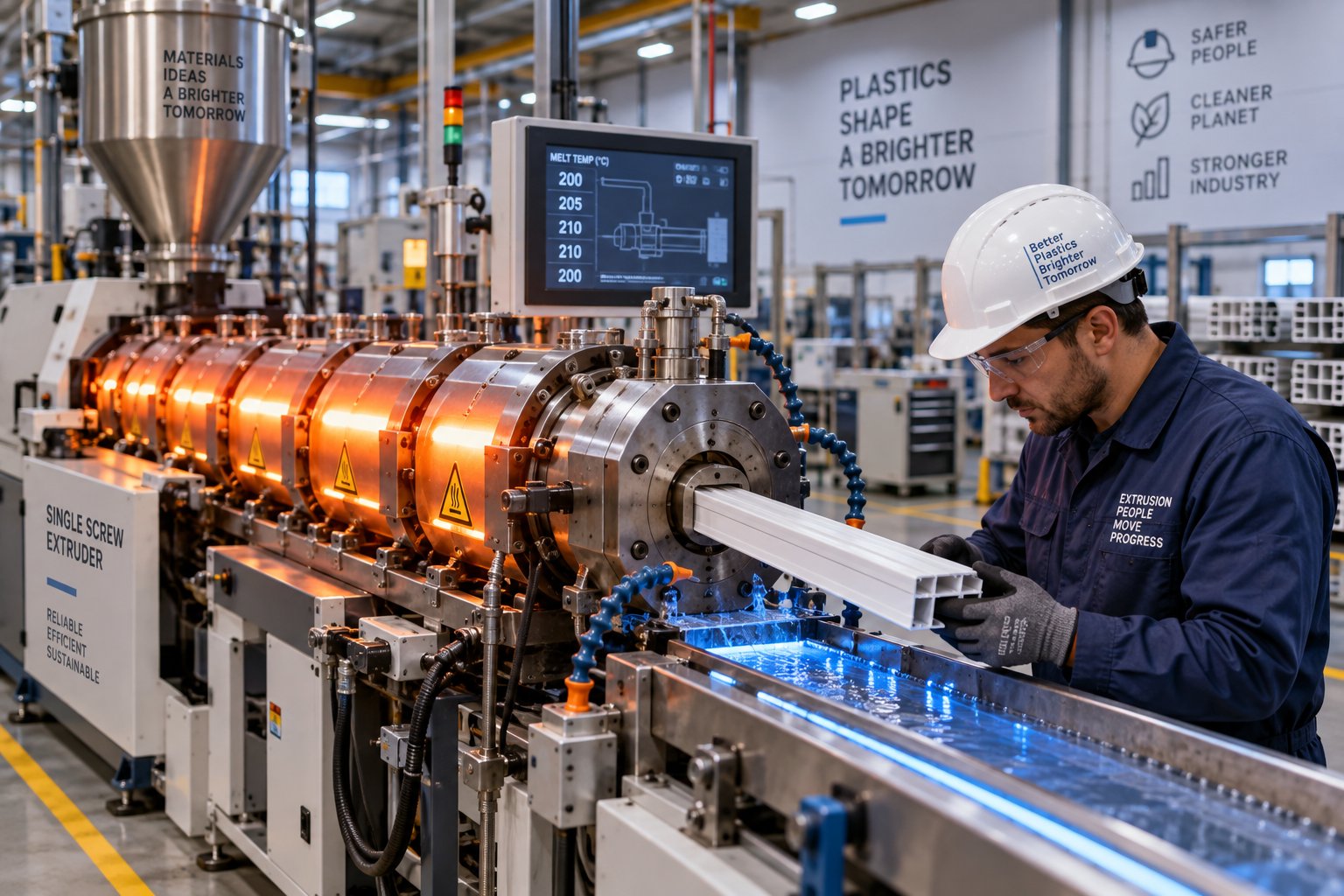
When Fixes Backfire: Extrusion Problems and Solutions Explained
Oct 12, 2026
Learn how to systematically diagnose and fix extrusion problems using a four-domain framework. Covers surface defects, surging, dimensional drift, material-specific fixes, and screw barrel design.
Read ArticleLooking for something else?
Search by material, symptom or product and jump straight to the relevant page.
These are navigation suggestions based on keyword matching — not a quotation, not a delivery commitment, and not a substitute for engineering review. Final specification is confirmed by our engineers against your drawings and processed material.
Need help with screw barrel selection?
Share your machine model, processed material and application. Our team can help with pricing and technical support.