

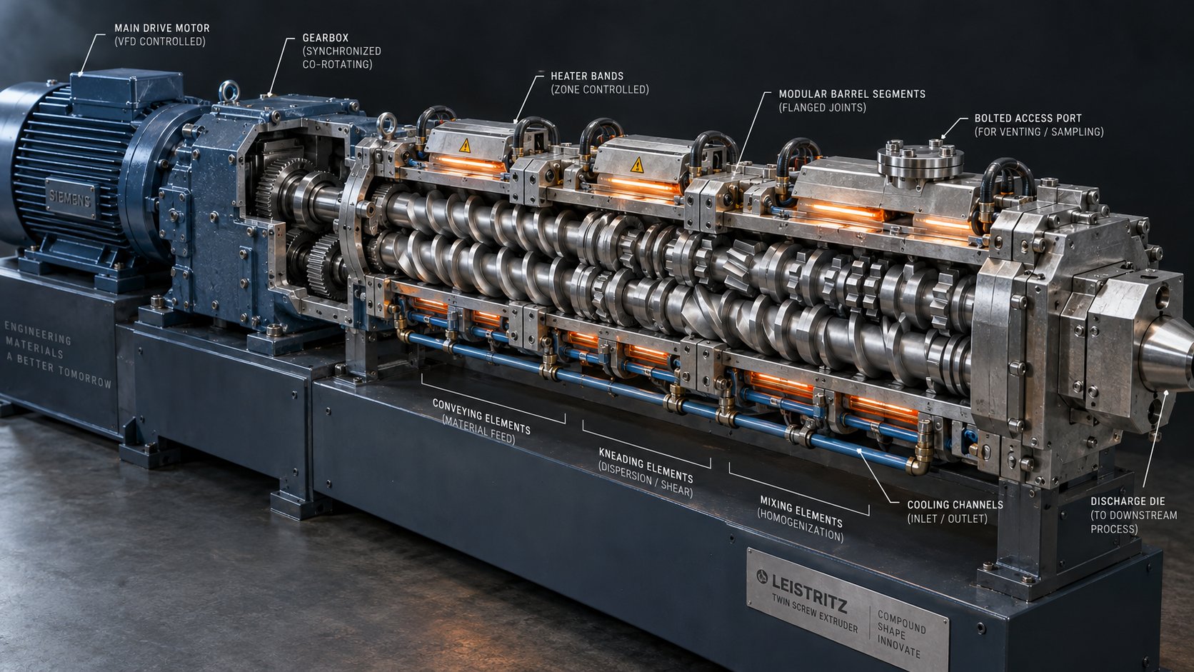
Anatomy of a Co Rotating Twin Screw Extruder
Imagine a machine that you can completely disassemble and rebuild like a set of industrial building blocks — swapping, rearranging, and customizing every segment to process an entirely different material. That is exactly what a co-rotating twin screw extruder offers. Yet most guides only scratch the surface, listing a handful of major assemblies without ever diving into the individual parts that truly determine performance. This article changes that by walking you through every component, from the drive motor all the way to the die face.
A co-rotating twin screw extruder is a continuous-process machine that uses two parallel, intermeshing screws — rotating in the same direction inside a segmented barrel — to feed, melt, mix, devolatilize, and pressurize polymers and other materials. Its fully modular construction allows engineers to reconfigure screw elements, barrel segments, and auxiliary components for virtually any compounding, masterbatch, or reactive extrusion application.
What Makes Co-Rotating Twin Screw Extruders Modular
The co rotating twin screw extruder working principle revolves around modularity. Rather than machining a single, fixed screw from one piece of steel, manufacturers build the screw profile by sliding individual elements — conveying segments, kneading blocks, and mixing discs — onto a common splined shaft. Each element performs a distinct task: transporting solids forward, melting polymer through shear, dispersing fillers, or sealing pressure before a vent port.
The barrel follows the same philosophy. Independent barrel sections bolt together in sequence, and each section can serve a unique purpose — a closed segment for melting, an open-port segment for side feeding glass fibers, or a vented segment connected to a vacuum pump for devolatilization. This modular twin screw extruder components explained approach means you can reconfigure one machine for dozens of different recipes simply by rearranging parts, rather than purchasing entirely new equipment.
Why Understanding Individual Parts Matters
Why should you care about each part in detail? Three practical reasons stand out:
- Performance optimization — Selecting the right screw element sequence and kneading block geometry directly controls mixing intensity, melt temperature, and residence time. Small changes in a single element can shift product quality dramatically.
- Wear troubleshooting — When throughput drops or product quality drifts, the root cause is almost always a worn part — a screw element with eroded flights, a barrel liner with an oversized bore, or a damaged kneading block. Knowing what each component looks like when new helps you spot degradation early.
- Smarter purchasing decisions — Replacement parts represent a significant operating cost. Understanding dimensional standards, material grades, and functional roles prevents costly ordering mistakes and helps you evaluate whether OEM or compatible aftermarket elements are the right choice.
A thorough co rotating twin screw extruder parts diagram in your mind — or pinned to your shop wall — is the fastest route to all three outcomes.
The OD/ID Ratio and Its Impact on Part Design
One number ties every part together: the OD/ID ratio, which is the relationship between the outer diameter and the inner diameter of the screw elements. Sounds abstract? Think of it this way. A higher OD/ID ratio (for example, 1.65 or 1.8) means the screw flights are deeper relative to the shaft core. Deeper flights create more free volume inside each barrel segment, allowing greater throughput and gentler processing of heat-sensitive materials. However, that deeper channel also means a thinner shaft core, which limits the maximum torque the screw can transmit.
Conversely, a lower OD/ID ratio (closer to 1.4 or 1.5) produces shallower channels with a thicker, stronger shaft core. This design handles higher torque loads and is well suited for processing highly filled or high-viscosity compounds where mechanical energy input is more critical than free volume.
The twin screw extruder OD ID ratio meaning extends directly into parts selection. Every screw element, kneading block, and barrel bore is manufactured to match a specific OD/ID specification. Mixing elements from different ratio families on the same shaft is not an option — the geometries simply will not intermesh correctly. So before you order a single replacement part, confirming your machine's OD/ID ratio is step one.
With this geometric foundation in place, the next logical question becomes: where does all the mechanical energy originate? The answer sits at the upstream end of every extruder — inside the drive system and gearbox.
Drive System and Gearbox Components
Every screw element, kneading block, and barrel segment depends on one thing: consistent, controllable mechanical energy delivered from the upstream end of the machine. The drive system is the power foundation that makes everything else possible. It converts high-speed, low-torque electrical energy into the slow, high-torque rotation that pushes viscous polymer melts through dozens of barrel diameters worth of processing zones. Getting these co rotating extruder drive system components right — or wrong — determines whether the rest of your carefully designed screw profile can actually do its job.
Motor and Speed Control Systems
At the head of the drive train sits an AC motor paired with a variable-frequency drive (VFD). The VFD is what gives you precise, stepless control over screw speed — typically ranging from about 15 RPM up to 600 RPM or more depending on the machine size and application. Why does this matter? Because screw speed directly governs shear rate, residence time, and throughput. A slight speed adjustment can mean the difference between a perfectly dispersed color concentrate and a streaky, under-mixed product.
Standard AC induction motors used in twin screw extruders operate at base speeds of 1,000 to 1,500 RPM (depending on pole count and supply frequency). The VFD modulates the frequency and voltage supplied to the motor windings, allowing the operator to dial in any speed within the operating range while maintaining full torque availability. Modern drives also provide overload protection, soft-start capability, and real-time torque monitoring — features that protect the gearbox and screw elements from damage during cold starts or unexpected process surges.
The motor connects to the gearbox through a flexible coupling. This coupling — typically an elastomeric disc or gear-tooth type — serves two purposes. First, it transmits rotational power. Second, it absorbs minor shaft misalignment and vibration between the motor and gearbox, preventing those forces from reaching the precision gear train inside. Choosing the right twin screw extruder motor and coupling parts is a detail that pays dividends in gearbox longevity, because even small misalignment at the input shaft multiplies into accelerated bearing and gear wear over thousands of operating hours.
Gearbox Internals and Torque Transmission
If the motor is the heart, the gearbox is the musculature. It performs three simultaneous engineering tasks that no other single component in the extruder can replicate:
- Speed reduction — Converting the motor's 1,000+ RPM output down to the screw's operating speed through two or three stages of helical gear pairs.
- Torque multiplication — As speed drops through each gear stage, torque rises proportionally (minus small efficiency losses of 1–2% per stage). A gearbox with a 30:1 ratio multiplies the motor's torque roughly 30 times.
- Axial thrust absorption — As the screws push molten polymer toward the die, an equal and opposite reaction force pushes back along the screw axis toward the gearbox. Thrust bearings inside the gearbox must absorb this force continuously — sometimes exceeding hundreds of kilonewtons in large machines.
Here is where twin screw gearboxes diverge sharply from their single-screw counterparts. A single-screw extruder gearbox has one output shaft, one gear train, and one thrust bearing assembly. A co-rotating twin screw gearbox must drive two parallel output shafts at an identical, synchronized speed and angular phase. Any timing error — even a fraction of a degree — causes the intermeshing screws to collide, potentially destroying both the screw elements and the gearbox internals.
To achieve this, modern gearboxes use a split-torque transmission design. Rather than driving one shaft and then gearing off it to spin the second, the split torque gearbox twin screw extruder configuration divides the incoming motor torque evenly across both output shafts through a dedicated synchronization gear set. This ensures each screw receives exactly 50% of the available torque, eliminating uneven loading that would cause one screw shaft to wear faster than the other. The synchronization gears also lock the angular relationship between the two shafts, maintaining the precise phase alignment that intermeshing screws require.
The table below breaks down the critical subcomponents inside a twin screw extruder gearbox, along with what each one does and how it typically fails when maintenance is neglected:
| Gearbox Subcomponent | Primary Function | Typical Failure Mode |
|---|---|---|
| Input shaft and pinion gear | Receives motor torque and initiates the first speed-reduction stage | Key fretting or spline wear from coupling misalignment |
| Intermediate gear stages | Provide additional speed reduction and torque multiplication across two or three helical gear pairs | Tooth surface pitting from contact fatigue or inadequate lubrication |
| Synchronization gear set | Splits torque evenly and maintains angular phase between both output shafts | Timing drift or tooth wear causing screw interference |
| Output shafts (x2) | Transmit final high-torque, low-speed rotation to screw shaft couplings | Spline or coupling bore wear from prolonged high-torque operation |
| Thrust bearing assembly (per shaft) | Absorbs continuous axial force generated by screw back-pressure against the die | Fatigue spalling from sustained overload or contaminated lubricant |
| Radial bearings | Maintain shaft position and absorb radial forces from gear mesh loading | Increased vibration and noise from wear or insufficient lubrication |
| Oil sump and lubrication system | Delivers clean, temperature-controlled oil to all gear meshes and bearings | Oil degradation, overheating, or contamination leading to cascading component failures |
| Shaft seals | Prevent oil leakage outward and contaminant ingress inward at shaft exit points | Lip wear allowing dust infiltration into the oil, accelerating gear and bearing wear |
Notice that lubrication-related issues appear in nearly every failure column. Industry data consistently confirms this pattern — more gearbox failures trace back to oil problems (wrong viscosity, low level, contamination, or overheating) than to any mechanical deficiency in the gears themselves.
How Torque Ratings Affect Processing Performance
You will often see a twin screw extruder gearbox torque rating expressed as "specific torque" in Nm/cm3 — the torque delivered per unit of screw cross-sectional area. This metric normalizes torque capacity across different machine sizes and makes apples-to-apples comparisons possible. A benchmark figure for many standard co-rotating machines sits around 10 to 11.3 Nm/cm3, while high-performance compounding extruders push to 15 Nm/cm3 or even 18 Nm/cm3 in the latest generation designs.
Why should you care about this number? Because specific torque directly dictates what materials your extruder can process and at what throughput. Imagine you are compounding a 40% glass-fiber-filled polyamide. The viscous resistance of that melt against the screw flights is dramatically higher than unfilled polypropylene. If your gearbox can only deliver 10 Nm/cm3, you may hit the torque ceiling long before you reach the machine's theoretical throughput capacity — essentially leaving production rate on the table. A gearbox rated at 18 Nm/cm3 on the same screw diameter could push up to 100% more material through the same barrel before reaching its torque limit.
The practical guideline most experienced operators follow: run at roughly 80% of the gearbox's continuous torque rating, not 80% of its peak rating. This distinction matters enormously. Peak ratings reflect short-duration capacity — useful for absorbing a cold-start surge, but not a number you should size your daily production around. Continuous ratings reflect what the thrust bearings, gear surfaces, and lubrication system can sustain hour after hour, shift after shift.
The OD/ID ratio discussed earlier ties directly into this torque story. A lower ratio (thicker shaft core, shallower channels) pairs with higher specific torque gearboxes for demanding, high-viscosity applications. A higher ratio (deeper channels, more free volume) pairs with moderate torque gearboxes for high-throughput, lower-viscosity processing. Matching your gearbox capability to your screw geometry is not optional — it is the engineering equation that determines whether your extruder runs at its design potential or limps along at a fraction of its capacity.
All of that mechanical energy ultimately enters the barrel, where it encounters the segmented, independently heated and cooled structure that shapes every thermal and pressure condition the polymer will experience along the process length.
Barrel System and Temperature Control Parts
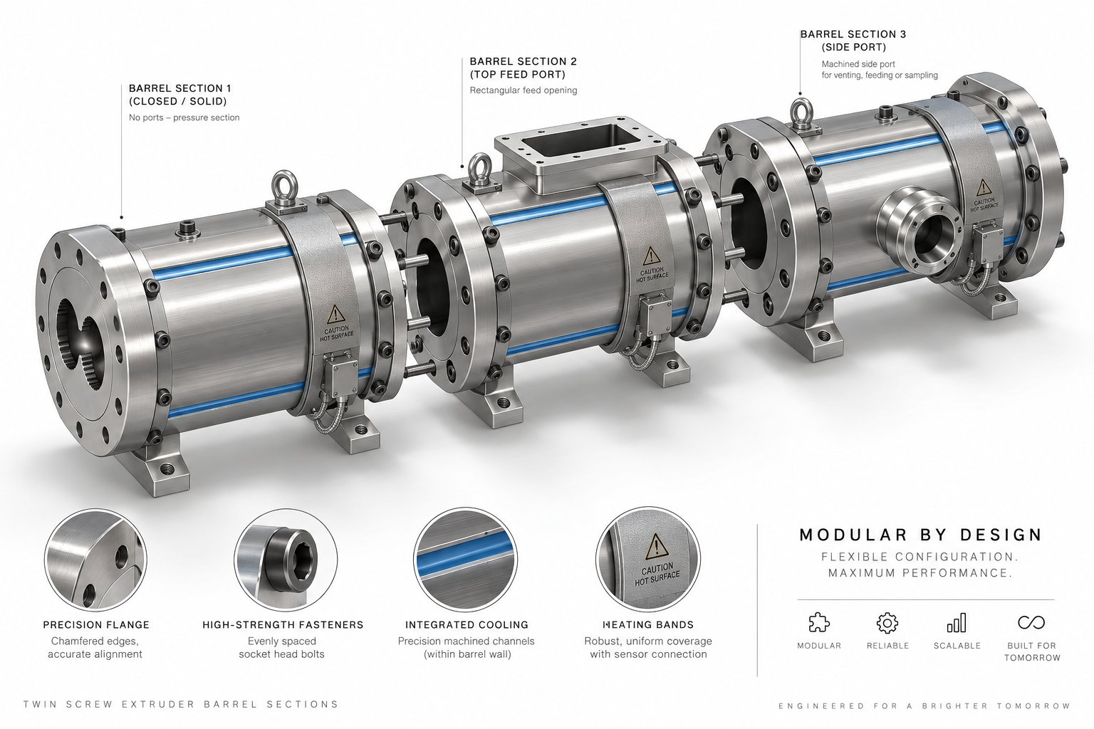
All of that rotational energy from the gearbox and motor has to go somewhere — and it enters a structure that is far more engineered than it appears from the outside. The barrel is not a simple tube. In a co-rotating twin screw extruder, it is a precision-machined, modular assembly of individual segments, each one independently heated, cooled, and monitored. Think of it as a series of miniature process reactors bolted end to end, where each segment creates a unique thermal and pressure environment for the polymer passing through. Getting the twin screw extruder barrel zone configuration right is just as critical as designing the screw profile itself, because the barrel controls the thermal boundary conditions that every screw element works against.
Segmented Barrel Construction and Zone Layout
Rather than boring a single long cylinder from a monolithic steel block, manufacturers build barrels from individual segments — typically four to six diameters long per section — that bolt together in a precise sequence using alignment dowels and heavy-duty flange bolts. The figure-eight bore running through each segment accommodates the two intermeshing screws, and internal alignment between neighboring sections must be held to very tight tolerances. Even a small step or offset at a barrel joint accelerates wear and disrupts melt flow.
What makes this modular approach so powerful is that each segment can serve a completely different function. You can rearrange, add, or remove sections to transform the same machine from a compounding line into a devolatilization system — often within a single shift. Here are the most common twin screw extruder barrel segments types you will encounter:
- Solid closed barrel — No openings; used in melting and high-pressure metering zones where you need full containment and maximum heat transfer.
- Feed barrel with port — Features a top opening aligned with the feed throat and hopper; this is always the first segment in the barrel stack.
- Vented barrel — Contains an opening (atmospheric or vacuum-connected) that allows moisture, trapped air, and volatiles to escape from the melt surface.
- Side-feed barrel — Incorporates a side opening for a secondary feeder, typically used to introduce glass fibers, mineral fillers, or other additives downstream after the polymer has already melted.
- Liquid-injection barrel — Includes a port fitted with an injection nozzle for introducing liquid additives, peroxides, or coupling agents directly into the melt stream at a controlled rate.
This modularity enables rapid reconfiguration for different processes. Some manufacturers have pushed the concept even further — CPM, for instance, offers a handwheel-operated barrel ejection system that allows individual segments to be slid apart for cleaning or inspection without heavy lifting equipment. Innovations like this reduce downtime dramatically when switching between product recipes or performing scheduled maintenance.
Heating Bands, Cooling Channels, and Temperature Control
Every barrel segment carries its own modular barrel heating and cooling system, creating an independently controlled thermal zone. This zone-by-zone precision is what makes a co-rotating twin screw extruder so versatile — you can run a steep temperature ramp for rapid melting, hold a plateau through a mixing section, and then cool down before a vent port, all on the same machine at the same time.
Two heating technologies dominate the industry:
- Cartridge heaters — Cylindrical resistance elements inserted into bores drilled directly into the barrel wall. They deliver fast, localized heat and are relatively easy to replace when one burns out. You will find these on many mid-range compounding machines.
- Cast aluminum heaters — Aluminum bands cast around the barrel exterior that provide more uniform heat distribution across the segment surface. They respond slightly more slowly than cartridge heaters but excel at maintaining even temperatures across wide processing windows.
Heating alone is not enough, though. During intensive kneading and mixing, viscous dissipation — the heat generated by shear within the polymer itself — can push melt temperatures well above the setpoint. That is where cooling channels come in. Each barrel segment includes internal passages that circulate water or thermal oil through the barrel wall to extract excess heat. A solenoid valve on each zone opens and closes in response to thermocouple feedback, forming a closed-loop control system that continuously balances heat input against heat removal.
Speaking of thermocouples — each zone houses at least one sensor (sometimes two for redundancy) positioned close to the barrel bore surface. These provide real-time temperature readings to the PLC or control panel, which then modulates heater output and cooling flow to hold the setpoint. Accurate thermocouple placement matters more than many operators realize. A sensor that sits too far from the bore measures barrel-wall temperature rather than true melt-contact temperature, leading to control offsets that can destabilize the process.
Barrel Liner Materials and Wear Protection
The inner bore surface of each barrel segment endures constant abrasion from rotating screw elements, filler particles, and corrosive polymer decomposition products. Without protection, a standard tool-steel bore could wear out of tolerance within months when processing glass-fiber-filled compounds or corrosive resins like PVC.
The industry standard solution is the bimetallic barrel liner for twin screw extruder applications. In this construction, a wear-resistant alloy — typically 1 to 2 mm thick — is metallurgically bonded to the inner surface of a structural steel barrel body through centrifugal casting. The base steel provides toughness and structural integrity, while the liner alloy delivers the hardness and chemical resistance needed at the contact surface. According to industry data from Juyuan Machinery, a well-selected bimetallic liner can deliver three to seven times the abrasion resistance of a standard nitrided barrel, depending on the alloy grade chosen.
The liner alloy itself varies based on the dominant wear mechanism:
- Iron-based alloys — Offer strong abrasion resistance and good cost-effectiveness; well suited for mineral-filled polyolefins and general compounding work.
- Nickel-based alloys — Provide superior corrosion resistance and are the go-to choice when processing chemically aggressive polymers such as PVC, fluoropolymers, or flame-retardant compounds that release acidic byproducts.
Choosing between these options is not guesswork. It comes down to understanding whether your primary barrel threat is abrasive wear from hard filler particles, corrosive attack from polymer decomposition chemistry, or a combination of both. Matching the liner grade to your actual process conditions keeps the screw-to-barrel clearance tight and stable, which in turn preserves melt-conveying efficiency and product consistency over thousands of production hours.
The barrel creates the thermal boundary — but the real processing magic happens on the parts rotating inside it. Each type of screw element mounted along the shaft performs a specific mechanical function, from simple forward conveyance to intense dispersive mixing, and the differences between them are more nuanced than most guides let on.
Screw Element Types and Their Processing Roles
The barrel sets the thermal stage, but the parts spinning inside it — the screw elements — dictate exactly what happens to the polymer at every position along the process length. Each element geometry creates a distinct combination of conveying force, pressure gradient, shear field, and residence time. Swap one element for another at the same barrel position and you can shift the process from gentle blending to aggressive dispersive mixing. With all twin screw extruder screw element types explained in the sections below, you will have the detailed vocabulary needed to read, design, or troubleshoot any screw configuration.
Forward Conveying Elements and Pitch Variations
Forward conveying elements are the workhorses of any screw profile. They look like classical helical screws with right-handed flights (designated "R" in most nomenclature systems), and their primary job is to grab material — whether it is solid pellets, powder, or molten polymer — and push it downstream toward the die. Their geometry is defined by two numbers: pitch (the axial distance between consecutive flights) and element length. An element labeled SE 30/30 R, for example, has a 30 mm pitch and a 30 mm length, with right-hand rotation.
Why do pitch variations matter so much? Because the screw element pitch ratio — the relationship between pitch and screw diameter — directly controls three processing variables simultaneously:
- Conveying capacity — A larger pitch moves more material per revolution. Deep-flight, wide-pitch elements (like SK 40/40 R thrust-edge designs) excel at grabbing bulk solids in the feed zone where you need maximum intake without compressing the material prematurely.
- Pressure build-up — A smaller pitch reduces the volume per flight and compresses the material into a tighter channel. Elements like SE 10/20 R generate significantly more pressure in the conveying direction but move less material per turn. Engineers place these reduced-pitch elements in the metering zone near the die, where building stable discharge pressure matters more than raw throughput.
- Shear input — Decreasing the channel depth or width increases the shear rate the material experiences. This means reduced-pitch elements do not just compress — they also contribute modestly to melting and temperature rise through viscous dissipation.
In practice, you will find forward conveying elements arranged in a deliberate pitch cascade along the screw shaft. Coarse-pitch elements sit at the feed throat to swallow solids aggressively. Mid-pitch elements follow in the transition and melting zone, where partial compression promotes barrel contact and heat transfer. Fine-pitch elements finish the profile in the metering section, squeezing the fully molten polymer to a uniform pressure before it enters the die. This descending-pitch architecture is not arbitrary — it mirrors the material's transformation from a loose, low-density solid into a dense, pressurized melt.
Reverse Elements and Melt Seal Formation
Reverse conveying elements — designated with an "L" for left-handed flight direction — are perhaps the most counterintuitive parts on the shaft. They are literally threaded backward, pushing material in the opposite direction to the overall flow. Why would you intentionally obstruct forward movement in a machine designed to convey material?
The answer lies in what that obstruction creates: a fully filled, pressurized zone immediately upstream. When material meets a reverse element, it cannot pass easily. The melt backs up, filling all available free volume in the preceding elements and generating a localized pressure peak. This fully filled region forms a melt seal — a continuous plug of polymer that acts as a gas-tight barrier between adjacent barrel sections.
Melt seals are essential before vent ports. Without one, the vacuum applied at a downstream devolatilization opening would pull air backward through partially filled conveying sections, destroying the pressure differential needed to extract moisture and volatiles. By placing a short reverse element (typically shorter than one screw diameter to avoid excessive pressure spikes) immediately upstream of the vent barrel, engineers guarantee that gases can only escape through the vent — not backward through the barrel.
Reverse elements also serve a second critical function: they dramatically increase residence time and shear intensity in the zone just upstream. Material recirculates and churns as forward-conveying pressure fights the backward push. This makes reverse elements valuable partners for kneading blocks in high-intensity mixing zones, especially in reactive extrusion where longer exposure to heat and mechanical energy drives chemical reactions toward completion. Research from NC State Extension confirms that reverse screw elements create maximum restriction to forward flow and therefore generate maximum shear — a property engineers exploit deliberately but sparingly, because the associated pressure and temperature rise can degrade sensitive polymers if overused.
Distributive Mixing Elements and Their Variants
Between the simple conveyance of forward elements and the brute-force restriction of reverse elements sits a family of specialized parts designed primarily to mix. These are the distributive mixing elements, and they fill a role that neither conveying elements nor kneading blocks handle well on their own: spreading additives, colorants, and minor components evenly throughout the melt without applying excessive shear stress.
Three main twin screw extruder mixing element designs — TME, SME, and ZME — appear across various manufacturers' catalogs, each with a distinct geometry and mixing philosophy:
- Toothed Mixing Elements (TME/ZME) — These feature rows of interlocking teeth rather than continuous helical flights. As the melt passes through, each tooth row splits, redirects, and recombines the flow stream. The result is powerful distributive mixing with near-zero dispersive shear — ideal for evenly spreading already-fine additives without crushing delicate filler structures like glass fiber or platelet talc. A 2024 study published in Polymers (MDPI) confirmed that the ZME consistently delivered the best distributive mixing quality among five screw element types tested, achieving the lowest mixing index (MQ) values across all rotation speeds — meaning the most uniform particle distribution in the melt cross-section.
- Screw Mixing Elements (SME) — These resemble conveying elements with interrupted flights or notched channels cut into the screw lands. The interruptions force melt to leak across flight tips and recombine in adjacent channels, generating repeated splitting and folding actions. SMEs provide a useful middle ground between pure conveyance and aggressive kneading, and they maintain a positive forward-pumping action that keeps the extruder running smoothly.
- Turbine Mixing Elements (TME) — Featuring lobed or gear-like cross sections, TMEs create complex three-dimensional flow patterns as the two screws intermesh. They excel in blending operations where both distributive and mild dispersive action are needed simultaneously, such as incorporating liquid additives or blending polymers of similar viscosity.
The critical takeaway here is that these mixing elements fill a gap. Kneading blocks — covered in the next section — generate high shear and intense energy input. Distributive mixing elements generate flow rearrangement with relatively low mechanical stress. For heat-sensitive formulations, fiber-reinforced compounds, or recipes where the additives arrive pre-ground and simply need uniform spatial distribution, TME, SME, and ZME elements accomplish the job without the temperature penalty that aggressive kneading blocks impose.
To put all of these element types in perspective, here is how they rank by forward conveying efficiency — the ability to move material toward the die per screw revolution:
- Large-pitch forward conveying elements (e.g., SK 40/40 R) — Highest conveying volume per revolution; minimal shear and pressure generation.
- Standard-pitch forward conveying elements (e.g., SE 30/30 R) — Balanced conveyance with moderate pressure capability.
- Reduced-pitch forward conveying elements (e.g., SE 10/20 R) — Lower conveying volume but highest pressure build-up among forward elements.
- Screw Mixing Elements (SME) — Maintain forward pumping action but at reduced efficiency due to interrupted flights.
- Toothed Mixing Elements (ZME/TME) — Weak positive conveying; primary function is mixing, not transport.
- Neutral kneading blocks (90° stagger) — Near-zero net conveying; material oscillates with no forward or backward bias.
- Reverse conveying elements (e.g., SE 20/20 L) — Negative conveying; actively push material backward, creating maximum flow restriction.
This ranking is not just academic. It directly informs screw profile design. You will always find high-efficiency conveying elements flanking mixing and kneading zones, ensuring that material is reliably fed into — and pulled out of — every restrictive section. Without that conveying support on both sides, even a well-chosen kneading block or mixing element can cause torque spikes, pressure surges, and process instability.
Conveying elements move material; mixing elements distribute it. But the most demanding processing tasks — breaking apart pigment agglomerates, deagglomerating nano-fillers, plasticizing crystalline polymers — require something with far more shear intensity. That role belongs to the kneading block, and its geometry offers a remarkably fine degree of control over mixing aggression.
Kneading Blocks and Mixing Intensity
Conveying elements transport polymer, and distributive mixing elements blend it — but neither one can break apart a stubborn pigment agglomerate or force two immiscible polymers into a fine-phase blend. That job demands concentrated mechanical energy delivered through intense shear and elongational flow fields. Kneading blocks are the co rotating twin screw extruder parts specifically engineered for this purpose, and their geometry gives you a remarkably precise dial to control exactly how aggressive — or gentle — that mixing action is.
Imagine stacking a series of thick coins on a rod, but instead of aligning them flat, you twist each successive coin by a fixed angle relative to the one beneath it. That twisted stack of discs is essentially what a kneading block looks like. The shape of each disc, the number of discs in the stack, the angular offset between them, and the width of each individual disc all determine whether the block gently folds material together or hammers it apart under tremendous shear stress. This section serves as your twin screw extruder kneading block configuration guide, breaking down the geometry and connecting it directly to the processing outcomes you can expect.
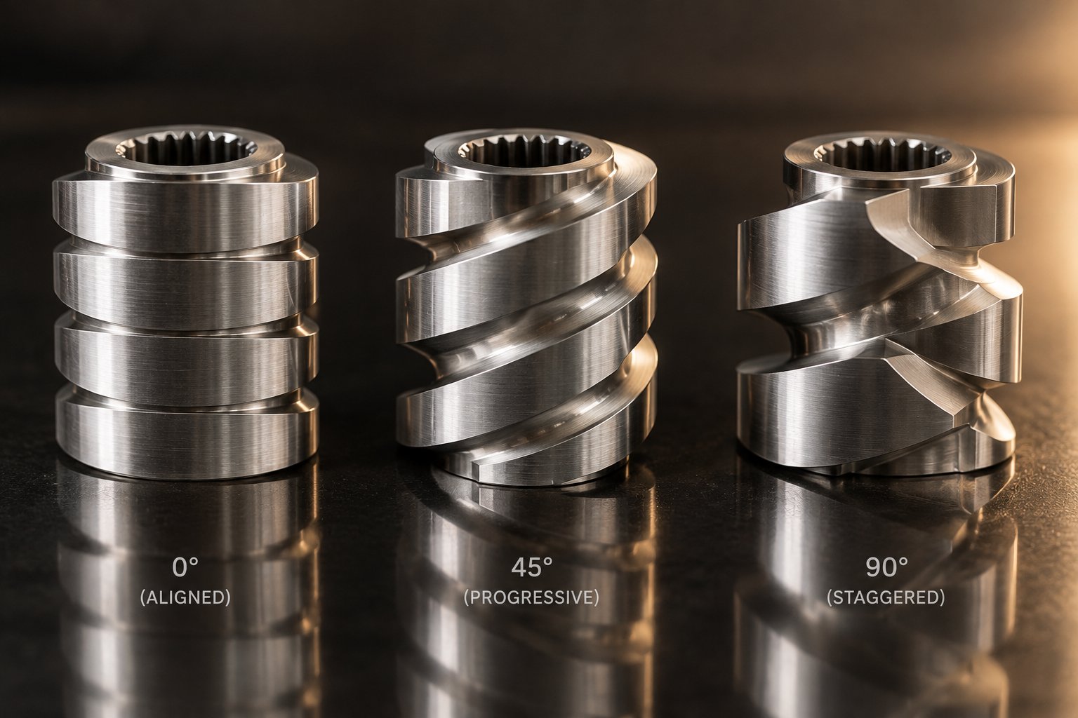
Kneading Block Geometry and Stagger Angles
A kneading block consists of multiple bilobed (double-headed) or trilobed (triple-headed) disc-shaped elements assembled on a common shaft segment. Each disc has a cross-sectional profile matching the Erdmenger self-wiping geometry — the same mathematical curve used for all intermeshing co-rotating screw elements. The critical difference from conveying elements is that kneading discs have no continuous helical flight. Instead, each disc is a discrete lobe that wipes against the barrel wall and the opposing screw's corresponding disc during rotation.
Three primary geometric parameters define any kneading block's behavior:
- Stagger angle — The angular offset between each consecutive disc in the stack. Common angles are 30 degrees, 45 degrees, 60 degrees, and 90 degrees. The kneading block stagger angle in a twin screw extruder controls conveying tendency and shear intensity simultaneously.
- Disc width — The axial thickness of each individual disc within the block. Narrow discs (sometimes designated KP in manufacturer nomenclature, indicating half-disk width on both sides) create more flow splits per unit length. Wide discs (often designated KBW, indicating full-disk width on both sides) fill more of the barrel cross-section and generate higher localized shear.
- Number of discs — More discs in the stack mean more sequential shearing events as material passes through the block. A five-disc block at 45 degrees covers a total angular span of 180 degrees, providing multiple reorientation steps for the melt.
The stagger angle deserves special attention because it determines whether the kneading block pushes material forward, holds it in place, or drives it backward. At low stagger angles like 30 degrees, consecutive discs overlap enough to create a partial forward-pumping effect — material spirals through the block with a net downstream movement, similar to a very aggressive conveying element. At 90 degrees, each disc sits perpendicular to its neighbor. No forward or backward pumping tendency exists. Material simply oscillates within the block, trapped between shearing surfaces with no directional bias. This neutral conveying behavior maximizes residence time in the block and dramatically increases energy input into the melt.
Reverse-staggered kneading blocks — where discs are offset in the left-hand direction — actively push material backward, mimicking the function of reverse screw elements but with the intense shear character of a kneading section. These are the most aggressive mixing elements available in any twin screw extruder parts catalog.
Dispersive vs. Distributive Mixing Effects
Why does disc width matter as much as stagger angle? Because the relationship between kneading block disc width and mixing intensity directly controls the balance between two fundamentally different mixing mechanisms.
Dispersive mixing breaks things apart. It applies shear stress and elongational stress high enough to rupture particle agglomerates, overcome surface tension holding droplets together, or fracture crystalline domains in a polymer matrix. Think of grinding a clump of pigment powder into individual primary particles — that is dispersive mixing at work. It requires high mechanical energy input and is primarily achieved through the shearing action between kneading disc tips and the barrel wall. Wider discs generate higher dispersive mixing because they present more surface area in the high-shear gap between the disc tip and the barrel bore. As industry data from Haisi Extrusion confirms, thicker kneading block discs produce greater shear with less distributive effect.
Distributive mixing spreads things evenly. It splits, reorients, and recombines flow streams repeatedly until every minor component — a colorant, an additive, a secondary polymer phase — is uniformly distributed throughout the melt without necessarily applying high mechanical stress. Narrower discs excel here because they create more frequent flow divisions per unit length of the kneading block. Each thin disc acts as an additional splitting point, and the material passes through more reorientation events in the same overall block length. The result is excellent spatial uniformity with lower energy input per unit mass — exactly what you want when working with heat-sensitive formulations or when filler particles are already at their target size and simply need even placement.
Here is a practical way to think about it. Picture shuffling a deck of cards. Distributive mixing is the repeated riffle shuffle that interleaves cards from two halves — it rearranges their positions without bending or tearing any individual card. Dispersive mixing is squeezing a stubborn, stuck-together clump of cards until they separate into singles. Kneading blocks can do both, and the ratio depends primarily on disc width and stagger angle working together.
The interplay between these two variables creates a broad spectrum of mixing behavior from a single element family, which is precisely why kneading blocks are the most versatile — and most frequently adjusted — parts in a co-rotating twin screw extruder screw profile.
Matching Kneading Blocks to Processing Tasks
Selecting the right kneading block configuration is not guesswork — it is a direct mapping of geometry to processing requirements. Different applications demand very different balances of shear, residence time, and thermal input. The table below connects the most common configurations to real-world processing tasks:
| Disc Width | Stagger Angle | Conveying Behavior | Dominant Mixing Type | Typical Application |
|---|---|---|---|---|
| Narrow (KP) | 30° forward | Moderate forward pumping | Distributive | Masterbatch production; gentle blending of pre-dispersed colorants |
| Narrow (KP) | 45° forward | Mild forward pumping | Distributive with light dispersive | Color concentrate compounding; blending of low-viscosity additives |
| Wide (KBW) | 45° forward | Mild forward pumping | Balanced dispersive and distributive | General polymer compounding; moderate filler incorporation |
| Wide (KBW) | 60° forward | Weak forward pumping | Primarily dispersive | Pigment deagglomeration; breaking down mineral filler clusters |
| Wide (KBW) | 90° neutral | Zero net conveying | Intense dispersive | Dispersing nano-fillers; high-viscosity polymer blending |
| Narrow (KP) | 45° reverse (L) | Mild backward push | High distributive with increased residence time | Reactive extrusion requiring extended mixing duration |
| Wide (KBW) | 45° reverse (L) | Moderate backward push | Maximum dispersive shear | Reactive extrusion; processing of highly filled engineering plastics |
A few practical patterns emerge from this table. For masterbatch production, where the goal is to distribute already-fine colorant particles uniformly through a carrier resin without overheating the melt, narrow-disc forward-staggered blocks at 30 or 45 degrees deliver the best results. The multiple thin discs create extensive flow splitting, and the forward stagger keeps material moving through the block efficiently, limiting temperature rise.
For pigment deagglomeration or dispersion of mineral fillers — where you must physically break apart clumps — wide-disc blocks at higher stagger angles are essential. A 60 degree forward-staggered wide block delivers strong shear while still nudging material downstream. A 90 degree neutral block takes that further, trapping material with zero net conveyance and forcing it through repeated high-intensity shearing cycles until agglomerates fracture. These neutral blocks are powerful tools, but they carry a temperature penalty. All of that shear energy converts to heat through viscous dissipation, so melt temperature rises significantly in 90 degree kneading zones.
Reverse-staggered kneading blocks — both narrow and wide variants — combine the shearing action of kneading disc geometry with the backward-pumping restriction of reverse conveying elements. They are reserved for the most demanding tasks: reactive extrusion processes where chemical conversion requires extended residence time and intense mechanical energy, or compounding of engineering plastics filled to 50% or more with glass fiber or carbon fiber. Because reverse kneading blocks simultaneously increase local pressure, temperature, and residence time, they should be used sparingly and always flanked by forward-conveying elements to prevent torque overload.
Beyond the standard double-headed designs, some manufacturers also produce triple-headed (trilobed) kneading blocks and hybrid combinations of double-headed and triple-headed discs within a single stack. Trilobed discs have three tips wiping the barrel per revolution instead of two, creating more frequent shearing events at the barrel wall. This geometry is particularly effective for crushing and grinding powdery raw materials entering the barrel, and it can enhance both striking and extrusion performance in the early compaction zone.
The key takeaway from this entire section is that kneading blocks are not interchangeable commodities — each configuration represents a deliberate engineering choice. A 45 degree narrow-disc block and a 90 degree wide-disc block may occupy the same shaft position, but they deliver fundamentally different processing outcomes. Selecting the right combination requires matching your material's rheology, your filler's particle characteristics, and your thermal sensitivity limits to the disc width and stagger angle that produce the desired result.
Kneading blocks and screw elements shape the polymer melt — but they cannot perform their roles without material being introduced at the right time, the right rate, and the right location along the barrel. The feed system and downstream addition components are the parts that make that possible.
Feed System and Downstream Addition Parts
Every screw element and kneading block you have read about so far is essentially useless if material does not reach it at the correct rate, at the correct location, and in the correct form. The feed system is the gatekeeper of the entire extrusion process — it determines how solids enter the extruder, how downstream additives join the melt stream, and how volatiles escape before the die. Yet twin screw extruder feed throat and hopper parts are among the most overlooked components in most parts discussions. That gap ends here.
Feed Throat and Hopper Configurations
The feed throat is the short transition piece that connects the hopper outlet to the top opening of the first barrel segment. It sounds simple, but its design has a direct impact on whether your extruder starves, floods, or feeds smoothly. The throat is typically water-cooled — a feature that often surprises newcomers. Why cool the very first thing the material touches? Because heat conducted backward from the first heated barrel segment can soften or partially melt polymer pellets inside the throat, causing them to stick to the walls, bridge across the opening, and choke off material flow entirely. A cooled feed throat keeps the entry surface well below the polymer's softening point, ensuring gravity and the screw flights — not friction — control the intake rate.
Sitting above the feed throat is the hopper, and its geometry varies depending on the material being processed. Standard conical hoppers work well for free-flowing pellets. Wedge-shaped hoppers with steep walls and narrow outlets suit powders that tend to rat-hole or bridge. For extremely poor-flowing materials — recycled flake, sticky additives, or hygroscopic powders — agitated hoppers fitted with stirring paddles, vibrating walls, or screw-type force feeders physically push material into the throat to prevent starvation.
One detail worth remembering: a co-rotating twin screw extruder almost always operates in starve-fed mode. Unlike a single-screw machine where the hopper gravity-fills the feed section to capacity, a twin screw extruder relies on a separate feeder upstream of the hopper to meter material at a precise, controlled rate. The screws themselves are deliberately underfilled in the feed zone. This starve-feeding approach gives operators independent control over throughput (set by the feeder) and shear energy (set by screw speed), rather than coupling both variables together as flood-feeding does.
Gravimetric vs. Volumetric Feeding Systems
The feeder sitting above the hopper is arguably the most process-critical peripheral on the entire line. It controls exactly how much material enters the extruder per unit time, and the choice between a gravimetric vs volumetric feeder for a twin screw extruder has real consequences for product consistency and waste.
Volumetric feeders dispense material based on volume — a screw or auger turns at a set speed, delivering a theoretically constant volume per revolution. They are simpler, less expensive, and perfectly adequate when material bulk density is stable and formulation precision requirements are moderate. Think of single-component applications with uniform pellets where density variations are minimal.
Gravimetric feeders add a continuous-weighing platform beneath the hopper. A load cell measures the actual weight loss per unit time, and a control loop adjusts the feeder screw speed in real time to maintain the target mass flow rate. When the bulk density of your raw material fluctuates — as it does with regrind, powder blends, or recycled flake — a gravimetric system compensates automatically. For multi-component formulations requiring tight ratio control (masterbatch coloring at 2% letdown, for instance), gravimetric feeding is not optional — it is the only way to hold additive ratios within specification across an entire production run.
Most compounding lines use a combination: a gravimetric loss-in-weight feeder for the primary resin and one or more additional feeders — either gravimetric or volumetric, depending on the precision required — for secondary additives fed at the same throat or downstream.
Side Feeders and Downstream Injection Ports
Not everything can — or should — enter through the main feed throat. Glass fibers would be broken apart by upstream kneading blocks. High-loading mineral fillers would overwhelm the melting zone. Liquid peroxides would flash off before they could react. These materials need to join the process downstream, after the polymer has already melted and established a stable conveying flow. That is the role of downstream addition ports on a twin screw extruder.
The most common downstream addition device is the side feeder — a small, dedicated screw conveyor (single-screw or twin-screw design) mounted to a barrel segment with a side opening. The side feeder for twin screw extruder compounding operations pushes solid additives laterally into the extruder barrel against the rotating screws, which then pick up and incorporate the material into the existing melt stream. Twin-screw side feeders are preferred for glass fiber and mineral fillers because their intermeshing action provides positive displacement and prevents material from backing up into the feeder barrel.
Here is the critical engineering detail most guides miss: the position of the side feeder along the barrel is not arbitrary, and it cannot be selected independently of the screw configuration. As extrusion engineering data from Haisi confirms, the side feeder position determines how much processing the added material receives after it enters the extruder. Install the feeder too far upstream, and glass fibers travel through excessive kneading and shear — destroying the fiber length that gives the final compound its mechanical strength. Position it too far downstream, and fillers arrive at the die poorly dispersed and inadequately wetted by the polymer melt.
The screw elements immediately surrounding the side feeder port matter just as much as the port location itself. Engineers typically place open-flight conveying elements directly under the side-feed opening to create enough free volume for the incoming material. Kneading blocks and mixing elements follow downstream to disperse and homogenize the additive into the melt. The sections before the side feeder handle melting and initial mixing of the base polymer. This means the side feeder position, the screw configuration, and the mixing intensity downstream all function as a single integrated system — not three independent choices.
Beyond side feeders, two other barrel-mounted components round out the downstream addition picture:
- Liquid injection ports — Fitted with precision injection nozzles, these barrel openings deliver liquid additives (coupling agents, peroxides, plasticizers, or reactive monomers) directly into the melt stream at a metered rate. Injection pressure must exceed the local melt pressure inside the barrel to prevent backflow through the nozzle.
- Atmospheric vent ports — Open barrel positions that allow trapped air, moisture vapor, and light volatiles to escape naturally from partially filled screw sections. These are typically placed in the early feed zone or just after initial melting.
- Vacuum vent ports — Connected to a vacuum pump via a vent stuffer (a small twin-screw device that prevents melt from climbing out the vent opening), these create sub-atmospheric pressure over the melt surface to extract residual solvents, moisture, and low-molecular-weight volatiles. Vent stuffers are themselves a wear part, requiring periodic inspection of their screw elements.
Taken together, the complete inventory of feed-zone and downstream-addition components on a typical compounding extruder includes:
- Water-cooled feed throat
- Main hopper (conical, wedge, or agitated)
- Primary feeder (gravimetric or volumetric)
- Side feeder(s) with dedicated barrel segment(s)
- Liquid injection nozzle(s) and metering pump(s)
- Atmospheric vent port(s)
- Vacuum vent port(s) with vent stuffer assembly
- Sight glass or vent cover plates for unused barrel openings
Each of these components is a discrete, replaceable part — and each one must be matched to the barrel position, screw configuration, and material characteristics of the specific process it serves. A side feeder barrel installed at the wrong zone, a vent port placed where no melt seal exists upstream, or a volumetric feeder asked to meter a fluctuating-density powder — any one of these mismatches can undermine an otherwise well-designed screw profile.
With all of these individual parts now laid out — drive components, barrel segments, screw elements, kneading blocks, and feed system hardware — the natural question becomes how they all fit together into a coherent, purpose-built screw configuration for a specific application.
How Screw Configuration Design Connects Every Part
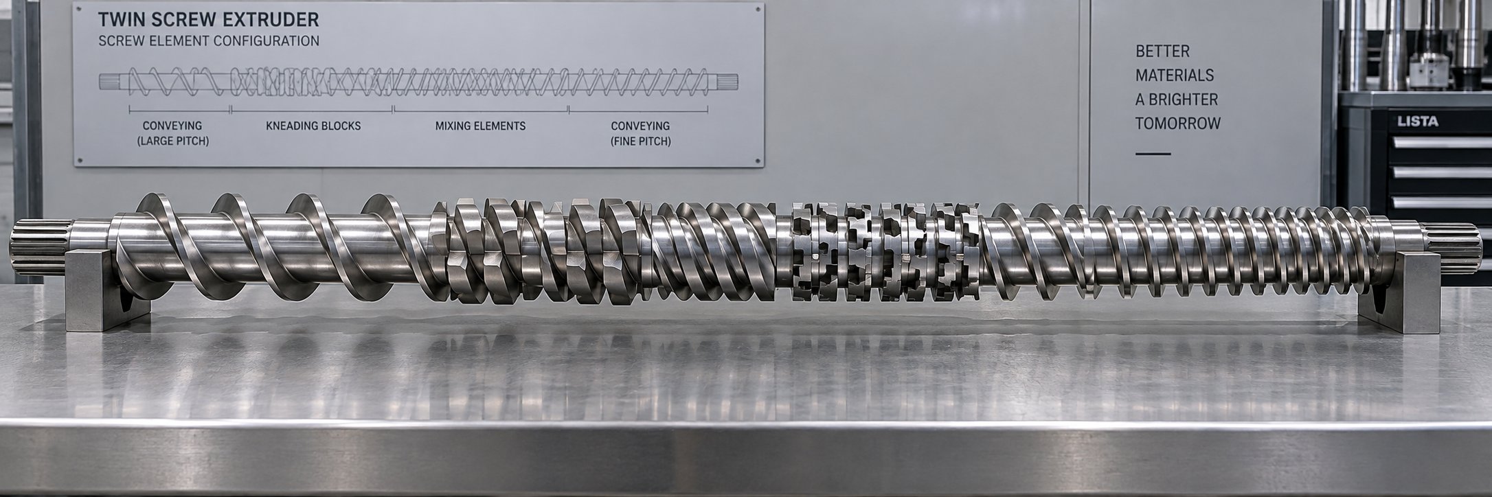
You now know what every individual part does — conveying elements push, kneading blocks shear, reverse elements seal, and mixing elements distribute. But knowing each part in isolation is like having a box of puzzle pieces without the picture on the lid. The real skill — the one that separates a smooth-running production line from a torque-limited, thermally unstable headache — is arranging all of these parts on the shaft in the right sequence. This section serves as your twin screw extruder screw profile design guide, connecting the component knowledge you have built so far into complete, application-specific screw configurations.
As NC State Extension puts it, configuring a screw for extrusion is a blend of art and science. No gold-standard profile exists that works for all materials and all extruder geometries, because every polymer exhibits unique flow properties influenced by temperature, shear rate, and machine dimensions. That said, clear principles govern how to arrange screw elements for twin screw extruder applications — and once you understand the logic, designing a profile for a new formulation becomes a systematic engineering exercise rather than blind trial and error.
Mapping Parts to Processing Zones
Every co-rotating twin screw extruder — regardless of manufacturer, size, or application — divides its process length into a series of functional zones. Each zone has a specific job, and that job dictates which screw element types belong there. Picture walking along the barrel from the feed throat to the die, and you will encounter these zones in roughly this order:
- Solids feed and conveying zone — The first few barrel diameters after the feed throat. Polymer pellets, powder, or flake drop into the screws and need to be grabbed and transported downstream as quickly as possible. Large-pitch, deep-flight forward conveying elements (like SK 40/40 R) dominate this zone because they maximize free volume and intake capacity without compressing or shearing the still-solid feedstock.
- Melting and plasticization zone — The region where solid material transitions into a melt. Pitch gradually decreases through transitional conveying elements, compressing material against heated barrel walls. Kneading blocks — typically forward-staggered at 30 to 60 degrees — then provide the intense shear needed to complete plasticization. Viscous dissipation from the kneading action generates significant internal heat, accelerating the melt transition.
- Mixing and dispersion zone — Immediately following melting, this is where additives, fillers, or secondary polymers are incorporated. The element selection here depends entirely on the mixing task. Wide-disc 90 degree kneading blocks deliver aggressive dispersive mixing for breaking apart filler agglomerates. Toothed mixing elements (ZME) or narrow-disc forward-staggered kneading blocks provide gentler distributive blending for pre-ground additives or colorants.
- Melt seal zone — A short section, typically one reverse element or reverse kneading block, placed directly before a vent port. This element creates a fully filled, pressurized plug of polymer that prevents gas from traveling backward through the barrel. Without this seal, vacuum devolatilization is impossible.
- Devolatilization zone — Located beneath a vented barrel segment. Forward conveying elements with moderate to large pitch keep the screw channels partially filled, exposing maximum melt surface area to the atmosphere or vacuum. This open surface allows moisture, trapped air, and residual solvents to escape.
- Metering and discharge zone — The final section before the die. Reduced-pitch forward conveying elements compress the melt, build stable discharge pressure, and ensure a uniform flow rate into the die or downstream pelletizer. Pressure stability here directly governs pellet weight consistency and die swell uniformity.
The key insight is that each zone is not defined by the barrel segment alone — it is defined by the combination of the barrel segment type and the screw elements occupying that position. A vented barrel with kneading blocks underneath it does not function as a devolatilization zone; it functions as a mixing zone that happens to leak volatiles poorly. Matching the right elements to the right barrel position is what transforms a collection of individual parts into a functioning process.
Screw Profile Design for Compounding Applications
Polymer compounding with mineral fillers — calcium carbonate, talc, or glass fiber — is the single most common application for co-rotating twin screw extruders. A screw configuration for polymer compounding extrusion needs to accomplish five things in sequence: intake the polymer, melt it, receive the filler through a side feeder, disperse and distribute the filler uniformly, and build enough pressure to push the compound through the die.
The table below maps a simplified but representative screw profile for a typical CaCO3-filled polyethylene compounding operation on a 40:1 L/D machine. Each row corresponds to a specific processing zone, the element types occupying that zone, and the function those elements perform:
| Processing Zone | Approximate L/D Position | Screw Element Types Used | Function in This Zone |
|---|---|---|---|
| Solids feed | 0–4 L/D | Large-pitch forward conveying (SK 40/40 R, SE 30/30 R) | Rapidly intake pellets from hopper; maximize free volume to prevent feed backup |
| Compression and melting | 4–10 L/D | Decreasing-pitch conveying elements transitioning to forward kneading blocks (KBW 45/5/30 R) | Compress solids against heated barrel wall; initiate plasticization through shear |
| Intensive plasticization | 10–14 L/D | Wide-disc kneading blocks (KBW 60° and 90°) flanked by short conveying elements | Complete polymer melting; generate homogeneous melt pool for filler incorporation |
| Melt seal (pre-side-feed) | 14–15 L/D | Short reverse element (SE 10/10 L) or reverse kneading block | Create fully filled zone to prevent air ingress at side-feed barrel opening |
| Side feeding | 15–17 L/D | Open-flight forward conveying (SE 30/30 R) | Accept mineral filler from side feeder; provide free volume for solids intake |
| Filler dispersion and distribution | 17–24 L/D | Wide-disc forward kneading blocks (KBW 45° R), toothed mixing elements (ZME), narrow kneading blocks (KP 45/5/20 R) | Break apart filler agglomerates (dispersive); spread filler uniformly through melt (distributive) |
| Melt seal (pre-vent) | 24–25 L/D | Short reverse element (SE 20/20 L) | Create gas-tight plug to isolate vent zone from upstream pressure |
| Vacuum devolatilization | 25–30 L/D | Moderate-pitch forward conveying (SE 30/30 R, SE 20/20 R) | Partially fill screw channels; expose melt surface to vacuum for moisture and volatile removal |
| Metering and pressure build-up | 30–38 L/D | Progressively decreasing-pitch conveying elements (SE 20/20 R, SE 10/20 R) | Fully fill channels; build stable, uniform die pressure |
| Die discharge | 38–40 L/D | Fine-pitch conveying elements (SE 10/20 R) | Final pressure stabilization; smooth melt delivery to die plate or pelletizer |
Notice the pattern: each zone transitions logically into the next. Conveying elements always flank restrictive elements (kneading blocks and reverse elements) to ensure that material flows into and out of every mixing section without torque spikes. The dispersive mixing zone uses a deliberate sequence — aggressive wide-disc kneading blocks first to crack filler agglomerates, followed by ZME or narrow kneading blocks for distributive homogenization — because breaking apart clumps is only half the job. Spreading those broken particles uniformly is the other half, and doing both in the right order produces a compound with consistent mechanical properties across every pellet.
Adapting Configurations for Devolatilization and Masterbatch
The compounding profile above is a starting point — not a universal solution. Different applications demand fundamentally different element arrangements, even on the same machine.
Devolatilization of residual solvents: When the primary process goal is stripping 5% to 30% volatile content from a polymer solution or wet feedstock, the screw profile shifts dramatically. The melting zone shrinks because many devolatilization processes feed a pre-dissolved or pre-melted polymer rather than dry pellets. In its place, you will find multiple melt-seal-to-vent sequences stacked in series — sometimes three or four vent zones in a 40:1 L/D barrel. Each sequence consists of a short reverse element forming a melt seal, followed by an extended section of moderate-pitch forward conveying elements under an open or vacuum-connected barrel port. The key to a twin screw extruder devolatilization screw profile is maximizing surface renewal — the rate at which fresh melt is exposed to the low-pressure zone above the partially filled screw channels. Increasing screw speed, reducing fill level under the vent, and using larger-pitch elements in the vent zone all increase surface renewal and improve stripping efficiency. Aggressive kneading blocks are largely absent from devolatilization profiles because their high shear and full-fill behavior work against the open, exposed-surface condition that devolatilization requires.
Masterbatch and color concentrate production: Here the challenge flips. You are typically working with a carrier resin loaded at 40% to 70% with pigments or additives. The pigment particles arrive pre-ground but agglomerated, and the processing goal is uniform dispersion at the lowest possible melt temperature to avoid thermal degradation of organic pigments. A masterbatch screw profile emphasizes multiple moderate-intensity mixing stages rather than a single aggressive dispersion zone. Narrow-disc forward kneading blocks (KP 45/5/20 R) appear in two or three separate mixing sections, each followed by a generous conveying section that allows the melt to relax and cool slightly before entering the next mixing stage. Reverse elements are used sparingly — just enough to create melt seals before any vent port, but not aggressively enough to spike melt temperature. ZME toothed mixing elements often replace wide-disc kneading blocks entirely in masterbatch profiles, because their exceptional distributive mixing capability — confirmed by 3D CFD flow simulations at the University of Paderborn — achieves the spatial uniformity that color quality demands without the thermal penalty of high-shear kneading.
The overarching lesson across all three applications is straightforward: screw profile design is not about choosing the "best" elements in isolation — it is about sequencing every part type along the shaft so that the material encounters exactly the right combination of conveyance, shear, mixing, and pressure at every point in its journey. The same kneading block that rescues a filler compounding recipe can ruin a devolatilization process. The same large-pitch conveying element that feeds solids perfectly can destroy pressure stability in the metering zone.
Every element on the shaft is a deliberate choice tied to what the polymer needs at that exact barrel position. And the material those elements are made from — the metallurgy, the surface treatment, the alloy grade — determines how long those deliberate choices continue to perform before wear changes the geometry and shifts the process out of specification.
Material Science Behind Extruder Wear Parts
A perfectly designed screw profile only stays perfect as long as the element geometry holds its original dimensions. The moment a kneading block tip wears down by a fraction of a millimeter, or a barrel bore opens up beyond its tolerance, every carefully engineered shear field and pressure gradient discussed in the previous sections begins to degrade. What determines how long those parts maintain their geometry? The answer is not mechanical design — it is metallurgy. The twin screw extruder screw element material grades and barrel liner alloys you select at the time of purchase define the effective lifespan of your entire screw configuration, and yet this is the topic most extruder parts guides skip entirely.
Screw Element Metallurgy and Surface Treatments
Screw elements operate in a brutally demanding environment. They rotate at speeds up to 600 RPM inside a tight-clearance barrel bore, shearing viscous polymer melts loaded with abrasive fillers, all while enduring continuous thermal cycling between 150 and 400 degrees Celsius depending on the resin. The steel or alloy beneath that element's flight tips must resist adhesive wear from polymer contact, abrasive wear from hard filler particles, corrosive attack from acidic decomposition products, and fatigue from cyclic torsional loading — all simultaneously and for thousands of operating hours.
Four broad material categories cover the vast majority of screw elements in service today, each suited to a different severity level:
- Nitrided tool steel (e.g., DIN 1.2344 / AISI H13) — The standard starting point. These are high-quality hot-work tool steels that undergo a gas or plasma nitriding process after machining, producing a nitrogen-diffused surface layer with hardness values reaching HV 900 to 1100. The hardened case is typically 0.3 to 0.5 mm deep, providing a wear-resistant shell over a tough, ductile core. Nitrided steel handles unfilled polymers and lightly filled compounds well and offers excellent cost-effectiveness for general-purpose compounding.
- Through-hardened tool steel (e.g., DIN 1.2379 / AISI D2) — Cold-work tool steels with higher chromium and carbon content than H13, heat-treated to uniform hardness of HRC 58 to 62 throughout the cross-section. These steels outperform nitrided grades when the nitrided surface case wears through prematurely — a common problem in moderately abrasive applications like talc-filled polypropylene or calcium carbonate compounds at 20 to 30% loading.
- Powder metallurgy (PM) HIP steels — This is where material science gets serious. Powder metallurgy steel for twin screw extruder parts is manufactured by atomizing molten alloy into fine powder, filling a mold, and consolidating it under extreme heat and pressure via Hot Isostatic Pressing (HIP). The result is a steel with an exceptionally fine, uniform carbide distribution — no carbide banding, no segregation, no weak spots. PM HIP grades like CPM 9V or CPM 10V contain high volumes of vanadium carbides that deliver abrasion resistance far beyond what conventional wrought steels achieve, while maintaining enough toughness to resist chipping under impact from hard filler particles. These grades are the go-to choice for processing compounds with 30% or more glass fiber, mineral filler, or ceramic microspheres.
- Tungsten carbide coated or stellite overlaid elements — For the most extreme wear environments, the base element is coated with a layer of tungsten carbide applied via thermal spray, laser cladding, or plasma-transferred arc welding. Tungsten carbide coated screw elements in an extruder can reach surface hardness values of HV 1300 to 1600 — roughly 50% harder than the best nitrided steels. Stellite overlays (cobalt-chromium alloys) provide a similar function but with better corrosion resistance, making them the preferred choice when both abrasion and chemical attack are present simultaneously, such as in halogen-free flame-retardant compounding.
The table below provides a practical comparison to help you match material grade to your specific application:
| Material Type | Typical Hardness Range | Best Suited Application | Relative Cost |
|---|---|---|---|
| Nitrided tool steel (H13 / 1.2344) | HV 900–1100 (surface) | Unfilled polymers, lightly filled compounds (<15% filler), color masterbatch | 1x (baseline) |
| Through-hardened tool steel (D2 / 1.2379) | HRC 58–62 (uniform) | Moderately filled compounds (15–30% CaCO3, talc), recycled materials with contaminants | 1.3–1.5x |
| Powder metallurgy HIP steel (CPM 9V / 10V) | HRC 60–64 (uniform) | Highly filled compounds (>30% glass fiber, mineral filler), abrasive engineering plastics | 2.5–4x |
| Tungsten carbide coating | HV 1300–1600 (surface layer) | Extreme abrasion environments; ceramic-filled compounds, high glass fiber loading (>50%) | 3–5x |
| Stellite overlay (Co-Cr alloy) | HRC 40–55 (overlay) | Combined abrasive and corrosive environments; flame-retardant compounds, PVC processing | 3–4.5x |
A common mistake is defaulting to the cheapest option. Nitrided H13 elements processing a 40% glass-fiber polyamide might last only 800 to 1,200 hours before flight-tip wear opens up the screw-to-barrel clearance enough to degrade mixing quality. The same position fitted with PM HIP elements could run 4,000 to 6,000 hours. When you factor in downtime for element changes, lost production, and the labor cost of disassembling a hot extruder, the higher upfront cost of premium metallurgy almost always pays for itself within the first replacement cycle.
Bimetallic Barrel Liners and Corrosion Resistance
Barrel wear follows different rules than screw element wear. Screw elements rotate and can be individually replaced on the shaft in a matter of hours. Barrels are static, bolted together, and significantly more expensive and time-consuming to swap out. That makes barrel liner longevity a higher-stakes decision — and it is exactly why bimetallic construction has become the industry standard for demanding applications.
As referenced in the barrel system chapter, a bimetallic barrel liner is created by centrifugally casting a wear-resistant alloy (typically 1 to 2 mm thick) onto the inner surface of a pre-machined structural steel tube. The barrel is heated, the lining alloy melts, and the assembly is rotated at high RPM as it cools — bonding the liner metallurgically to the base steel in an inseparable, void-free layer. The result is a composite structure: the outer steel body provides mechanical strength and thermal conductivity for heating and cooling, while the inner alloy liner delivers the hardness and chemical resistance that the bore surface needs.
This bimetallic barrel liner material selection guide breaks down the two primary liner families:
- Iron-based alloys (e.g., Fe-B type) — Contain boron carbides and chromium carbides dispersed in an iron matrix. They provide excellent abrasion resistance and are the cost-effective default for general-purpose compounding with mineral fillers, glass fibers, and recycled materials. Iron-boron liners handle moderate corrosive exposure but can degrade when processing halogenated polymers or strongly acidic additive systems over extended periods.
- Nickel-based alloys (e.g., Ni-Cr-B-Si types with tungsten carbide additions) — Offer dramatically superior corrosion resistance compared to iron-based grades, making them essential for PVC compounding, fluoropolymer processing, and formulations containing brominated flame retardants or acidic coupling agents. Higher-tier nickel alloys incorporate increasing percentages of tungsten carbide particles — variants rated for less than 15%, less than 30%, and up to 50% glass fiber loading provide progressively higher wear resistance at progressively higher cost. For the most chemically aggressive environments, HIP-cast nickel-based liners with zero iron content eliminate any risk of iron-catalyzed corrosion reactions with halogenated polymers.
Facilities processing corrosive materials without appropriate liner selection report barrel life as short as two to three years — compared to eight to ten years with a properly matched nickel-based bimetallic liner, according to field data from corrosion-intensive compounding operations. That four-to-five-fold difference in service life makes liner selection one of the highest-return material decisions on the entire machine.
Choosing the Right Material Grade for Your Application
How do you match all of these options to your specific process? Start by identifying the two dominant wear mechanisms your parts will face:
- Abrasive wear — Caused by hard filler particles (glass fiber, calcium carbonate, talc, titanium dioxide) scraping against element flights and barrel bore surfaces. The harder and more angular the filler, the more aggressive the abrasion. Glass fiber is particularly destructive because its Mohs hardness (around 6.5) exceeds that of many tool steels.
- Corrosive wear — Caused by chemical attack from polymer decomposition products (hydrogen chloride from PVC, hydrogen fluoride from PVDF), acidic additives, moisture-driven hydrolysis, or reactive processing byproducts. Corrosion softens the metal surface, and the softened layer is then stripped away by normal mechanical contact — accelerating total material loss far beyond what either mechanism would cause alone.
When abrasion dominates and corrosion is minimal — think polyolefins filled with calcium carbonate or talc — nitrided steel or through-hardened tool steel elements paired with iron-based bimetallic barrel liners deliver the best cost-to-performance ratio. When corrosion dominates — PVC, fluoropolymers, or brominated flame-retardant compounds — nickel-based barrel liners and stellite-overlaid screw elements become necessary regardless of filler loading. And when both mechanisms hit simultaneously — glass-fiber-reinforced engineering plastics processed with acidic coupling agents, for instance — PM HIP screw elements paired with nickel-carbide barrel liners represent the only material combination that provides acceptable service life.
Sounds expensive? It can be. But here is the economic reality that experienced compounders understand: the cost of wear parts is not the purchase price — it is the total cost per kilogram of good product produced before the parts need replacement. A set of PM HIP elements costing four times more than nitrided steel but lasting five times longer under abrasive conditions actually reduces your per-kilogram wear cost by 20% while cutting your changeover downtime in half. Matching material grade to actual process severity is not a luxury — it is the foundation of cost-effective operation.
Material science determines how long your parts last. But eventually, even the best metallurgy reaches its wear limit. Knowing when that limit arrives — and how to source replacement parts that maintain dimensional precision and material quality — is the practical knowledge that keeps your extruder running at peak performance shift after shift.
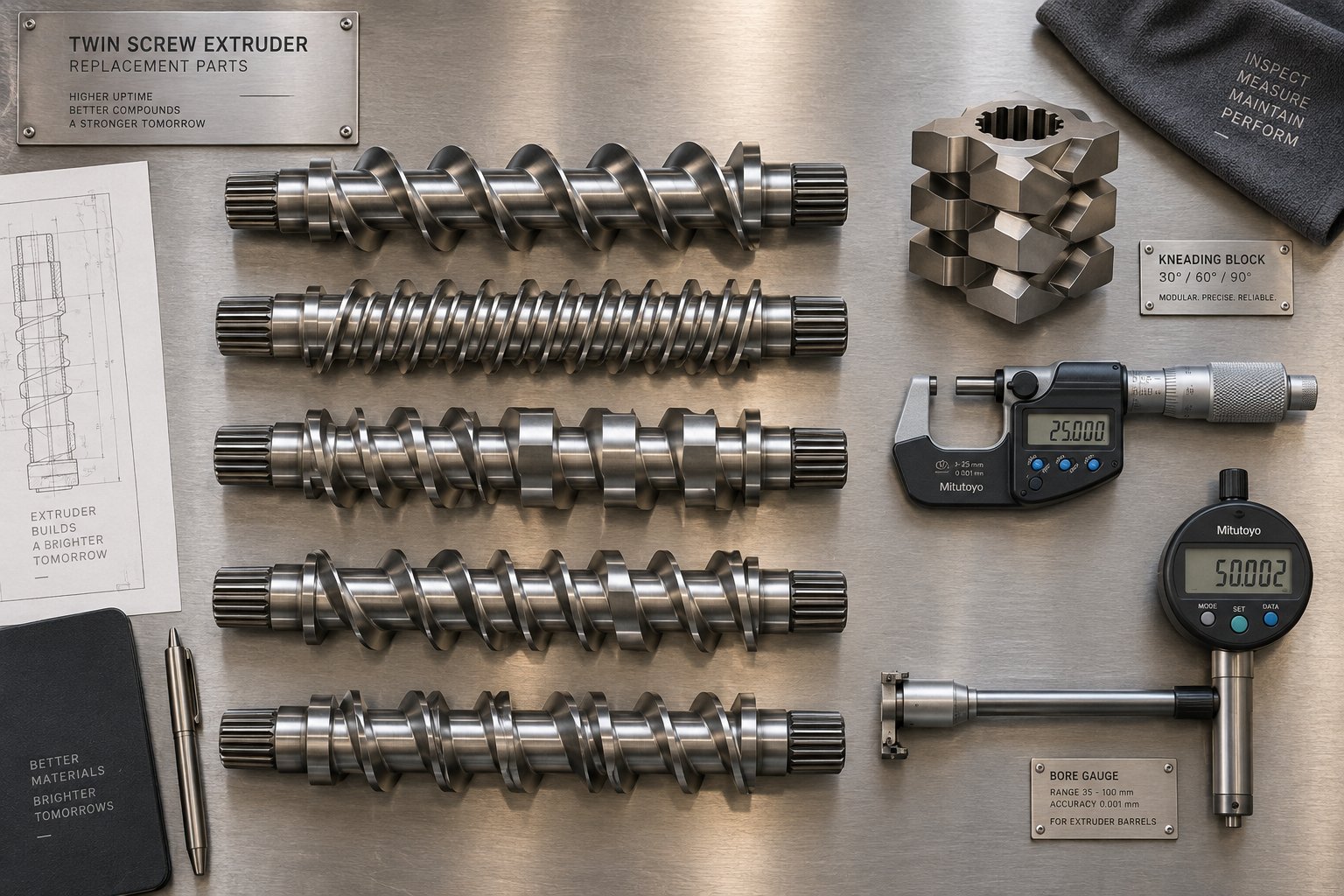
Sourcing and Replacing Twin Screw Extruder Parts
Even PM HIP elements running in nickel-carbide-lined barrels eventually reach their dimensional limits. When that moment arrives, the decision shifts from metallurgy to logistics: where do you source replacement screw elements for a twin screw extruder, how do you verify that the new parts will fit and perform identically to the originals, and how do you know the right moment to pull the trigger on a changeover? Getting these answers wrong can mean installing parts that introduce vibration, degrade mixing quality, or — in a worst case — physically interfere with the opposing screw and damage both shafts.
OEM vs. Compatible Replacement Screw Elements
When a screw element wears out, you face two sourcing paths. The first is ordering directly from the original equipment manufacturer — the company that built the extruder. OEM parts guarantee dimensional compliance with the machine's original engineering drawings, and they arrive with full traceability on material grade, heat treatment, and quality inspection records. The downside? Lead times can stretch to weeks or months, especially for less common element geometries, and pricing typically reflects the brand premium built into proprietary supply chains.
The second path is compatible aftermarket replacement parts. Because co-rotating twin screw extruders follow well-established dimensional conventions — shaft bore diameters, spline tooth counts, element outer diameters, and length increments are standardized within each machine family — qualified third-party manufacturers can produce elements that are dimensionally and metallurgically equivalent to OEM originals. The modular element-on-shaft design that makes these machines so versatile also makes them inherently open to multi-source supply, since each element is a self-contained unit that slides onto a standard splined shaft.
The key when evaluating OEM vs compatible twin screw extruder spare parts is not brand loyalty — it is dimensional verification and material certification. A compatible element machined to the correct spline profile, OD tolerance, and material hardness performs identically to an OEM part. One machined to looser tolerances or from an inferior alloy creates problems that may not surface until hundreds of hours into a production campaign, when premature wear reopens the clearances you just paid to restore.
Suppliers like NANHAIYA, which specializes in modular screw segments, screw elements, and kneading blocks for compounding, recycling, masterbatch, and pelletizing applications, represent the type of focused aftermarket manufacturer worth evaluating. When screening any replacement parts supplier — NANHAIYA or otherwise — look for these capabilities: CNC-machined spline bores held to OEM tolerances, documented material grades with hardness test reports, and the ability to supply the full range of element types (conveying, kneading, mixing, and reverse) for your specific machine series.
Critical Dimensions and Specifications for Parts Sourcing
Ordering the wrong element is easier than you might think. Two conveying elements can look nearly identical on a shelf yet differ in shaft bore diameter by half a millimeter — enough to prevent installation or cause dangerous looseness on the shaft. Before placing any order, verify these twin screw extruder parts sourcing specifications against your machine's documentation or by measuring the original parts directly:
- Shaft bore diameter — The internal hole that slides over the splined shaft. Must match the shaft OD within the manufacturer's specified clearance (typically a few hundredths of a millimeter).
- Spline count and profile — The number of teeth, the tooth form (involute or straight-sided), and the pitch diameter. An element with the correct bore but wrong spline count will not engage the shaft and cannot transmit torque.
- Element outer diameter (OD) — Must match the barrel bore geometry and the opposing screw's element OD to maintain proper intermeshing clearance and self-wiping function.
- Element length — Co-rotating extruders use standardized length increments (often multiples of the screw diameter, such as 0.5D, 1.0D, or 1.5D). Mixing different length systems on one shaft can leave gaps or extend the screw beyond the barrel.
- Material grade and surface treatment — Specify the alloy designation (H13, D2, CPM 9V, etc.) and treatment (nitrided, through-hardened, tungsten carbide coated) to ensure wear resistance matches your process demands, as detailed in the previous chapter.
- Element type and geometry code — The manufacturer's designation (e.g., SE 30/30 R, KBW 45/5/60 R) that defines pitch, disc count, stagger angle, and conveying direction. Ordering by description alone without confirming the geometry code risks receiving a functionally different element.
A practical tip: before your first aftermarket order, pull one representative element from each type on your shaft and measure it with a micrometer and spline gauge. Record those dimensions in a parts specification sheet that lives with the machine documentation. This sheet becomes your purchasing reference for every future order and eliminates the back-and-forth of verifying specs with the supplier each time.
Inspecting Wear and Knowing When to Replace Parts
Knowing how to inspect worn twin screw extruder parts is what separates reactive maintenance — scrambling after quality falls apart — from proactive replacement that keeps your process stable. Three inspection methods cover the critical wear indicators:
Screw element outer diameter measurement. Using a micrometer or caliper, measure the OD at the flight tips of each element after pulling the screws from the barrel. Compare the reading to the original design dimension. As Kailida's wear assessment guidelines recommend, if clearance between the screw flight tip and the barrel bore has increased by less than 30% from its original value and process performance remains stable, you can often continue running with adjusted process parameters. Once flight height has been reduced by more than 50% of its original dimension, or clearances significantly exceed the design limit, conveying and mixing functions are compromised and the affected elements should be replaced.
Visual wear pattern analysis. Worn elements tell a story if you know how to read them. Uniform polishing across flight tips indicates normal abrasive wear — expected and predictable. Localized gouging or scoring on one side suggests barrel misalignment or a bent screw shaft. Pitting and surface roughness point to corrosive attack. Black discoloration or material buildup in flight roots signals stagnation zones created by excessive clearance. Each pattern points to a different root cause and a different corrective action — replacing the element alone only fixes the symptom if the underlying cause (misalignment, wrong material grade, process temperature) remains unaddressed.
Barrel bore diameter checks. Barrel wear is slower than screw element wear but equally consequential. Using a bore gauge at multiple points along each barrel segment — especially at the intermeshing zone where both screws meet — reveals whether the bore has opened up beyond tolerance. A worn barrel with an oversized bore reduces the effectiveness of every new screw element you install into it, because the restored element-to-barrel clearance is only as tight as the wider of the two surfaces allows. This is why experienced maintenance teams measure both the screw elements and the barrel bore during every inspection, rather than assuming the barrel is still within spec.
The modular design philosophy that runs through every chapter of this article pays its biggest dividend at replacement time. You do not need to discard an entire screw shaft because three kneading blocks in the mixing zone are worn. You do not need to replace a full barrel because one segment near the side feeder has an oversized bore. Pull the worn segments, slide on new ones, and you are back in production — often within a single shift. That modularity, combined with informed material selection and disciplined inspection routines, is what transforms co rotating twin screw extruder parts from a recurring cost center into a manageable, predictable element of your operating budget.
Frequently Asked Questions About Co Rotating Twin Screw Extruder Parts
1. What are the main parts of a co rotating twin screw extruder?
A co rotating twin screw extruder consists of five major part families: the drive system (motor, gearbox, coupling), the segmented barrel assembly (heated and cooled barrel sections with various port configurations), the screw elements (forward conveying, reverse conveying, and distributive mixing elements mounted on splined shafts), kneading blocks (disc-stacked elements that control dispersive and distributive mixing intensity), and the feed system (hopper, feed throat, gravimetric or volumetric feeders, side feeders, liquid injection ports, and vent assemblies). Each component is modular and interchangeable, allowing engineers to reconfigure the machine for different polymers, fillers, and processing goals without replacing the entire extruder.
2. How do kneading block stagger angles affect mixing performance?
Kneading block stagger angles directly control both mixing intensity and conveying behavior. A 30-degree forward stagger creates moderate forward pumping with primarily distributive mixing, ideal for gentle blending of pre-dispersed colorants. A 45-degree stagger offers a balance between dispersive and distributive action for general compounding. A 60-degree forward stagger delivers primarily dispersive mixing suited to pigment deagglomeration. A 90-degree neutral stagger provides zero net conveying and maximum shear residence time, best for breaking down nano-fillers or blending high-viscosity polymers. Reverse-staggered blocks push material backward for maximum shear in reactive extrusion. Disc width further modifies this behavior — wider discs increase dispersive shear, while narrower discs multiply flow-splitting events for better distribution.
3. When should I replace worn twin screw extruder screw elements?
Industry guidelines suggest monitoring the clearance between screw element flight tips and the barrel bore. If the clearance has increased by less than 30% from its original design value and product quality remains acceptable, continued operation with adjusted parameters is generally safe. However, once the flight height has been reduced by more than 50% of its original dimension or screw-to-barrel clearance significantly exceeds the manufacturer's specification, conveying efficiency and mixing quality degrade noticeably, and the affected elements should be replaced. Visual inspection also helps — uniform tip polishing indicates normal abrasive wear, while localized gouging may signal barrel misalignment, and pitting points to corrosive attack requiring a material grade upgrade.
4. What is the difference between OEM and compatible aftermarket twin screw extruder parts?
OEM parts come directly from the extruder manufacturer with guaranteed dimensional compliance and full material traceability, but they often carry longer lead times and premium pricing. Compatible aftermarket parts are produced by specialized third-party suppliers like NANHAIYA (nhyscrews.com), which manufactures modular screw segments, screw elements, and kneading blocks for compounding, recycling, masterbatch, and pelletizing operations. Because co rotating twin screw extruders use standardized shaft bore diameters, spline profiles, and element length increments, qualified aftermarket manufacturers can produce dimensionally and metallurgically equivalent replacements. The critical evaluation criteria are identical for both paths: verify shaft bore diameter, spline count, element OD, length increment, material grade, and surface treatment against your machine's original specifications.
5. How does the OD/ID ratio affect twin screw extruder part selection?
The OD/ID ratio — the outer diameter divided by the inner diameter of the screw elements — is the fundamental geometric parameter that ties every part together. A higher ratio (1.65 to 1.8) creates deeper screw channels with more free volume, enabling higher throughput and gentler processing of heat-sensitive materials but limiting maximum torque due to a thinner shaft core. A lower ratio (1.4 to 1.5) produces shallower channels with a thicker, stronger core capable of handling higher torque loads for viscous or heavily filled compounds. Every screw element, kneading block, and barrel bore is manufactured to match a specific OD/ID specification, and mixing parts from different ratio families is impossible because the intermeshing geometries will not align. Confirming your machine's OD/ID ratio before ordering any replacement part is essential.
Written by
Nanhaiya Technical Team
Zhoushan Nanhaiya Plastic Machinery Co., Ltd.
The Nanhaiya technical team supports screw and barrel manufacturing projects through application review, technical communication, custom manufacturing coordination, and production and quality control.
Discuss Your Application
Related Articles
More insights on screw barrel technology and plastics processing.

What Nobody Tells You About Screw Barrel For Plastic Machine Design
Oct 10, 2026
Learn how screw barrel for plastic machine design affects melt quality, throughput, and wear life. Covers geometry, resin matching, troubleshooting, and sourcing.
Read Article
Single Screw Extruder for Sheet: Stop Guessing, Start Specifying
Oct 9, 2026
Learn how to specify a single screw extruder for sheet production. Covers screw geometry, resin-specific processing, troubleshooting, and maintenance best practices.
Read Article
PE Pipe Extruder Machine: What Datasheets Won't Tell You
Oct 9, 2026
Learn how a PE pipe extruder machine works, key specs explained, material grade selection, maintenance tips, and buyer guidance beyond the datasheet.
Read ArticleLooking for something else?
Search by material, symptom or product and jump straight to the relevant page.
These are navigation suggestions based on keyword matching — not a quotation, not a delivery commitment, and not a substitute for engineering review. Final specification is confirmed by our engineers against your drawings and processed material.
Need help with screw barrel selection?
Share your machine model, processed material and application. Our team can help with pricing and technical support.