

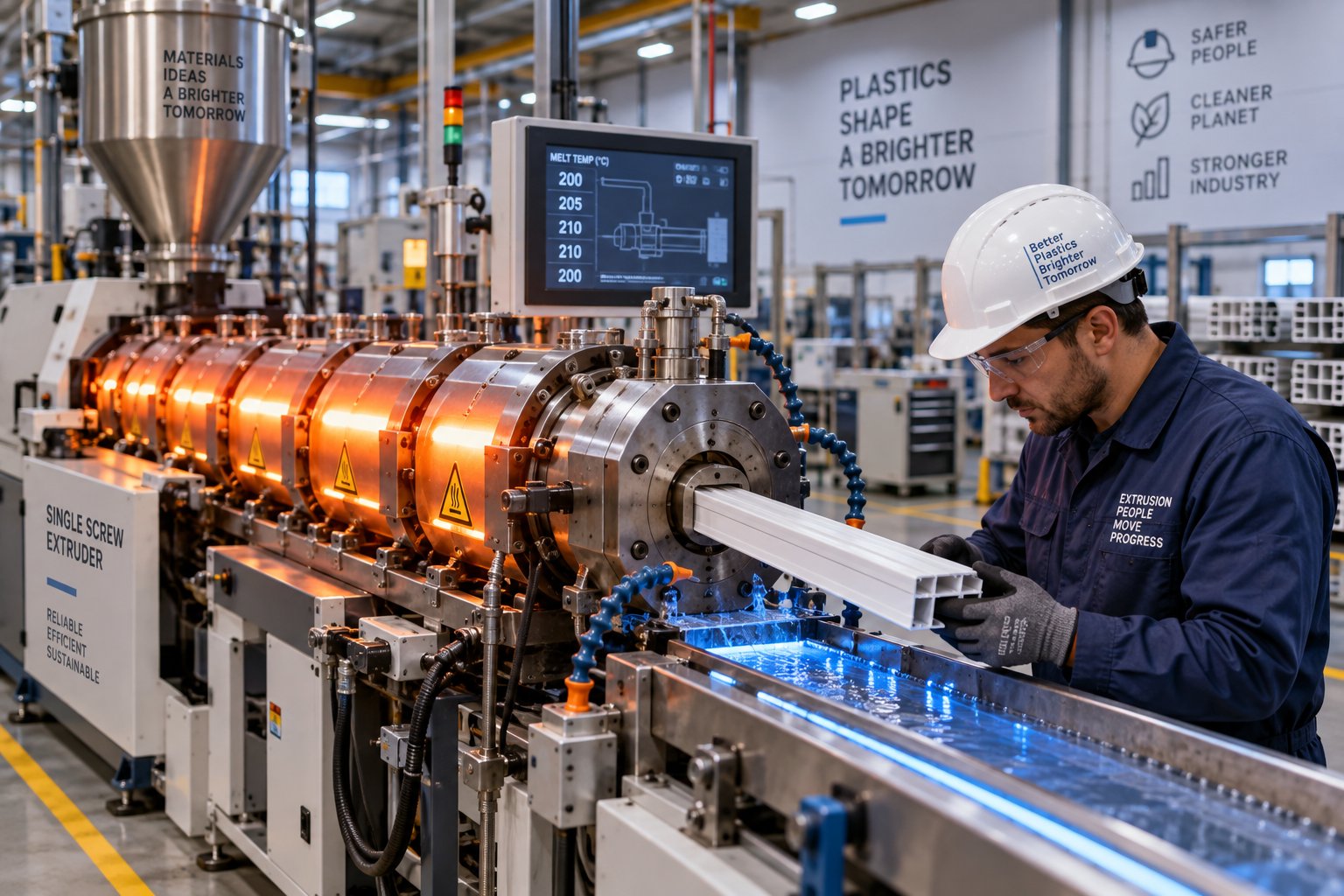
Why Extrusion Problems Demand a Systematic Approach
Imagine you walk onto the production floor and notice a faint roughness creeping across the surface of your extruded profile. An hour later, a quality inspector flags dimensional drift on a pipe run. Across the plant, an operator reports a yellowish discoloration on sheet that was running perfectly yesterday. Each of these symptoms looks different, yet they share something in common: they are signals, not diagnoses. The real question is never just "what went wrong" but "where in the process did the fault originate, and why?"
That distinction matters more than most plants realize. When operators react to visible defects by tweaking the nearest temperature dial or bumping screw speed, they are treating symptoms instead of causes. Worse, a hasty adjustment in one zone often triggers a brand-new defect somewhere else. A structured, root-cause-first approach to common extrusion problems and solutions is the only reliable way to break this cycle.
Why Extrusion Problems Cost More Than You Think
Scrap material is the cost everyone counts first. Raw material multiplied by wasted volume gives you a number that looks concrete and manageable. Yet that figure tells only a fraction of the story. Every minute an extrusion line runs out of specification, you are also burning machine capacity that can never be recovered. Unlike off-spec resin, which can sometimes be reground and reblended, lost machine time is gone permanently.
Consider the cascading expenses that pile up around a single quality event: downtime for investigation, engineering hours consumed by reactive problem-solving, rework labor, expedited shipping to meet delivery windows, and the administrative overhead of managing customer complaints. In high-throughput extrusion, raw materials can represent up to 80% of total production costs, so even a slight improvement in first-pass yield delivers outsized savings. Factor in the engineering talent diverted from process innovation to daily firefighting, and the true cost of extrusion quality problems on the production floor becomes far heavier than the scrap bin suggests.
The Four Domains Behind Every Extrusion Defect
Every extrusion defect, no matter how complex it appears, traces back to one or more of four interacting domains. Thinking of these domains as a diagnostic lens helps you isolate where a problem starts before you change anything on the machine. Here is the framework:
- Material — Resin properties, moisture content, additive packages, and batch-to-batch variation directly influence melt behavior. A subtle shift in melt flow index from one lot to the next can trigger surging or surface roughness that mimics a machine fault.
- Machine — Screw and barrel condition, drive performance, feed system integrity, and cooling circuit function define the mechanical foundation of a stable process. Gradual screw flight wear, for example, reduces pressure-building capacity and quietly erodes output over months.
- Die — Die geometry, lip condition, flow-channel cleanliness, and alignment determine how the melt exits the extruder. Damaged die lips or plate-out buildup inside the land area produce die lines and streaks that no barrel temperature adjustment can eliminate.
- Process Settings — Temperature profiles, screw speed, feed rate, line speed, and downstream parameters such as cooling bath temperature and vacuum calibration pressure form the operating envelope. Incorrect combinations narrow the processing window and invite defects from multiple directions at once.
These four domains do not operate in isolation. A worn screw (machine) changes the shear history of the polymer (material interaction), which shifts the melt pressure at the die (die), forcing the operator to adjust temperatures (process settings). Understanding how to troubleshoot extrusion issues effectively means recognizing these connections before reaching for any single control.
How This Guide Is Organized
This article follows a symptom-first, root-cause-back structure designed for real shop-floor use. Instead of listing generic tips, each section starts with the defect you can see or measure, then walks backward through the four-domain framework to identify where the fault originates and what corrective action actually resolves it. You will find step-by-step diagnostic sequences, polymer-specific guidance, and practical tables mapping symptoms to probable causes.
The goal is straightforward: give you a repeatable extrusion defect root cause analysis method that replaces guesswork with structured problem-solving. Whether you are chasing melt fracture on a blown film line or battling dimensional instability in pipe production, the diagnostic logic remains the same.
That logic begins with a question every experienced operator eventually asks: when multiple symptoms appear at once, where do you start?

A Diagnostic Framework for Isolating Extrusion Defects
Most extrusion troubleshooting goes sideways not because operators lack experience, but because they skip the investigation and jump straight to adjustments. You see rough surface texture, so you raise melt temperature. Output drops, so you bump screw speed. Each change feels logical in isolation, yet random parameter tweaking is the single fastest way to turn one defect into three. A disciplined extrusion root cause isolation process protects you from that trap.
The key principle is simple: diagnose the pattern before changing the process. Determine whether a defect is continuous or intermittent, whether it tracks with the machine direction or stays fixed in a cross-direction position, and whether it appeared suddenly or crept in over weeks. That context alone eliminates half the possible causes before you touch a single control.
Step-by-Step Root Cause Isolation Process
Think of extrusion troubleshooting step by step as a funnel. You start wide, confirming what you actually observe, then narrow systematically until only one or two plausible causes remain. Here is the sequence experienced process engineers follow:
- Document the symptom precisely. Describe what changed, where on the product it appears, and when it started. A vague note like "bad surface" wastes time. A specific entry like "transverse ridges appearing on the upper surface, approximately 2 mm apart, starting at 10:15 a.m." gives you something to work with.
- Determine whether the defect appeared suddenly or gradually. A sudden onset often points to a discrete event: a new material lot, a heater failure, a screen change, or a maintenance activity. Gradual drift suggests wear, slow contamination buildup, or a creeping calibration error.
- Rule out material changes first. Confirm the resin lot, regrind percentage, moisture level at the feed throat, and additive package. A surprising number of defects trace to an upstream material switch that nobody communicated to the operator. As one practical troubleshooting guide puts it, start at the resin source because it is easy to blame the screw or die when the real problem began in storage, drying, or blending.
- Inspect mechanical components for wear. Check screw flight condition, barrel bore measurements, feed throat integrity, and screen pack status. Gradual output decline at constant RPM or rising motor load for the same throughput are telltale signs of mechanical degradation, not process-setting problems.
- Review recent process parameter changes. Pull up the data logs. Did someone adjust barrel zone temperatures on the previous shift? Was screw speed increased to meet a production target? Correlate the timing of any parameter change with the onset of the defect.
- Examine die condition and downstream equipment. Inspect die lips for damage, plate-out, or contamination. Check puller speed calibration, cooling bath temperatures, and vacuum calibration pressure. Defects that appear uniform at the die exit but worsen downstream point to a post-extrusion cause.
Why does order matter? Because upstream causes cascade downstream. If inconsistent feeding is starving the screw, adjusting die temperatures or puller speed only masks the real issue while introducing new variables that complicate future diagnosis.
Reading Extruder Indicators Like an Expert
Your extruder constantly broadcasts diagnostic information through its instruments. The challenge is learning how to isolate extrusion defect causes by reading those signals together rather than in isolation.
Melt pressure trends are your most direct window into process stability. Steady pressure with tight variation means the screw is delivering consistent output. Cyclic pressure oscillations, on the other hand, signal surging, and the oscillation period helps identify the source. A real-world case involving a PVC pipe line illustrates this well: the plant observed pressure swings between 90 and 120 bar combined with motor amperage variation of plus or minus 15 percent. Initial suspicion pointed toward material variation, but detailed inspection revealed hopper bridging, screw wear beyond tolerance, and temperature instability in the metering zone, all contributing simultaneously.
Motor amperage shifts reveal how hard the screw is working. A rising motor load at constant RPM with falling output is a classic indicator of screw and barrel wear, not a temperature problem. The worn flights lose conveying efficiency, forcing the drive to work harder to push less material forward. Conversely, a sudden amperage drop can indicate feed starvation, where the screw is spinning but has nothing to convey.
Barrel zone temperature deviations tell you whether your heating and cooling systems are maintaining the intended melt profile. A zone that consistently overshoots its setpoint may have a failed cooling solenoid or a thermocouple reading incorrectly. A zone running cold despite full heater output suggests a damaged heater band or poor contact with the barrel wall. For reliable extruder melt pressure fluctuation diagnosis, overlay pressure, amperage, and temperature data on the same time scale. Patterns invisible in any single trend often become obvious when the signals are compared side by side.
When Multiple Symptoms Appear Simultaneously
Here is the scenario that overwhelms even experienced operators: you notice surface roughness, dimensional drift, and discoloration all at the same time. Three defects, seemingly unrelated, each suggesting a different root cause. Where do you begin?
The answer is upstream. Always work from the feed end of the extruder toward the die and beyond. The reason is physics: a problem in the feed zone or screw affects every downstream zone. Inconsistent solid conveying, for example, creates uneven melting, which produces pressure fluctuations, which cause dimensional variation, which shows up as surface defects at the die exit. What looks like three separate problems is actually one root cause expressing itself at multiple points along the process path.
Prioritize your investigation this way:
- Feed zone and hopper — Verify material flow, feed throat temperature, and hopper condition before anything else.
- Screw and barrel — Confirm that conveying, compression, and metering sections are performing within specification.
- Barrel temperature profile — Ensure each zone is holding setpoint and that the overall melt profile supports complete, uniform melting.
- Die and downstream — Only after upstream factors are cleared should you focus on die condition, puller calibration, and cooling equipment.
This upstream-first discipline prevents the most common troubleshooting mistake in extrusion: fixing a downstream symptom while the real fault quietly persists at the feed end, ready to generate the next defect the moment you look away.
And that feed end, it turns out, harbors some of the most overlooked failure modes in all of extrusion, problems that rarely appear in troubleshooting guides yet account for a disproportionate share of output instability.
Feed Zone and Hopper Problems That Undermine Output
The feed zone sits at the very beginning of the extrusion process, yet it receives the least troubleshooting attention. Operators naturally gravitate toward the die end, where defects become visible, and toward barrel temperature profiles, where adjustments feel immediate and controllable. Meanwhile, the hopper and feed throat quietly starve the screw of consistent material, seeding every downstream defect the team will spend hours chasing. Understanding extruder feed zone problems and fixes is essential to eliminating instability at its source.
When feed delivery varies even slightly, the screw alternates between fully loaded and partially loaded conditions. That variation carries through the compression and metering zones, amplifies into melt pressure oscillations, and ultimately shows up as dimensional drift, surface defects, or output shortfalls. Fixing any of those visible symptoms without addressing feed consistency is like repainting a wall while the roof still leaks.
Bridging and Rat-Holing in the Hopper
Two failure modes dominate hopper performance, and they look deceptively similar from the outside: output drops and the operator sees material sitting motionless in the hopper while the screw runs empty below. The difference lies in what is happening inside the hopper itself.
Bridging occurs when a stable arch forms across the hopper outlet, completely blocking material discharge. The particles lock together mechanically or through cohesive forces, creating a self-supporting structure that suspends the entire material column above the feed throat. Factors such as particle size, moisture content, and environmental conditions all influence the likelihood of bridge formation. Sticky or high-moisture pellets, powder blends with excessive fines, and hoppers with shallow wall angles are the most frequent culprits. Electrostatic charge, common with certain polyolefin pellets, also promotes particle-to-particle adhesion that strengthens the arch.
Rat-holing is more subtle and harder to detect. Instead of a complete blockage, a narrow channel forms through the center of the material bed, allowing resin to flow through that preferential path while stagnant material clings to the hopper walls. The result is inconsistent feed rate rather than a total stoppage. As the channel diameter fluctuates, output surges and dips in an unpredictable pattern. Cohesive forces between particles and particle size segregation contribute to the formation of these stable flow channels, especially in materials with wide particle size distributions.
Effective hopper bridging and rat-holing solutions target the root mechanics of each problem:
- Hopper geometry modification — Steeper wall angles (typically 60 degrees or greater from horizontal) reduce the opportunity for arching. A mass-flow hopper design, where all material moves simultaneously, virtually eliminates rat-holing.
- Vibrator installation — External vibrators break incipient bridges before they stabilize. Placement matters: mount the vibrator on the converging section near the outlet, not at the top of the hopper where it simply compacts the material above.
- Flexible-wall hopper or mechanical agitation — External paddles that massage a flexible hopper wall keep material in constant motion without damaging particles. This approach avoids the drawbacks of internal agitators, which can create dead zones or degrade fragile pellets.
- Crammer feeder addition — For materials that resist gravity feeding entirely, a crammer feeder positively forces material into the feed throat, decoupling hopper flow behavior from extruder feeding consistency.
- Antistatic treatment — Grounding the hopper and applying antistatic coatings or ionizing bars reduces electrostatic adhesion, particularly effective for PE and PP pellets in low-humidity environments.
Feed Throat Temperature Control in Extrusion
The feed throat is a deceptively critical transition zone. It connects the hopper, which holds solid pellets at ambient temperature, to the barrel, which is actively heated. Managing this boundary determines whether solids convey efficiently into the screw channel or prematurely soften and block the entry.
An overheated feed throat causes pellets to begin melting before they reach the screw flights. The softened material smears against the barrel wall and feed throat surface, forming a sticky layer that resists solid conveying. Output drops, motor amperage falls because the screw has less material to work against, and the process becomes erratic. This condition is especially dangerous with low-melting-point resins like LDPE or EVA, where the temperature margin between solid conveying and premature melting is narrow.
An under-cooled feed throat creates the opposite problem. While it prevents premature melting, excessive cooling can condense atmospheric moisture on the feed throat surface, particularly in humid plant environments. Condensation wets the pellets, promotes bridging, and in the case of hygroscopic resins like nylon or PET, introduces moisture directly into the melt stream. Even without condensation, an overly cold throat can reduce the friction between pellets and the barrel wall in the early screw flights, which diminishes the grip needed for effective solids conveying and lowers throughput.
A practical diagnostic shortcut: if output drops and motor amps are simultaneously low, check feed throat cooling water flow and temperature before adjusting anything else. The combination of low throughput and low drive load almost always points to a feeding deficiency rather than a downstream restriction.
Regrind and Mixed-Pellet Feeding Challenges
Most extrusion plants do not run 100 percent virgin resin. Cost pressures and sustainability commitments drive blending of regrind material back into the feed stream. The challenge is that regrind behaves fundamentally differently from virgin pellets in the feed zone, and ignoring those differences invites chronic output instability.
Research from the University of Stuttgart confirms what many operators observe on the floor: regrind particles have lower bulk density and irregular shapes compared to uniform virgin pellets. In grooved feed zone extruders, this reduced bulk density directly lowers the specific throughput per screw revolution. The extruder compensates by generating higher melt temperatures, which narrows the processing window and increases the risk of thermal degradation. In short, regrind feeding problems in extrusion are not just an inconvenience; they shrink the margin for error across the entire process.
Three mechanisms drive regrind-related instability:
- Particle size variation — Regrind flakes and chunks vary widely in size, causing uneven packing in the screw channel. Large pieces bridge across flights while fines sift through gaps, producing cyclical surging.
- Bulk density differences — Volumetric feeders deliver a consistent volume, not a consistent mass. When regrind and virgin material have different bulk densities, a volumetric blender produces fluctuating mass flow even though the volume looks steady. Gravimetric blending, which measures actual weight per unit time, eliminates this error.
- Inconsistent regrind quality — Regrind quality shifts with every production changeover. Color contamination, mixed resins, and degraded material from purge slugs all enter the regrind stream unless strict grinding protocols are enforced.
Consistent regrind grinding practices, including screen size standardization and dedicated regrind bins by resin type, are low-cost interventions that pay for themselves quickly. When combined with gravimetric blending, they bring regrind-heavy feed streams much closer to the stability of virgin-only operation.
The following table maps the most common feed zone symptoms to their likely upstream causes and the corrective actions that resolve them:
| Symptom | Likely Feed-Zone Cause | Corrective Action |
|---|---|---|
| Complete output stoppage with full hopper | Bridging across hopper outlet due to moisture, fines, electrostatic charge, or shallow hopper angle | Install vibrator near outlet; increase hopper wall angle; add crammer feeder; apply antistatic treatment |
| Irregular surging with material visible along hopper walls | Rat-holing creating a preferential flow channel through the center of the hopper | Redesign to mass-flow hopper geometry; use flexible-wall agitation; break up stagnant zones with air pads or mechanical assists |
| Gradual output decline with low motor amps | Overheated feed throat causing premature pellet softening and smearing; or under-cooled throat reducing solid conveying friction | Verify cooling water flow rate and temperature at feed throat; clean any polymer buildup from throat surface; adjust cooling setpoint |
| Cyclic output variation correlated with regrind percentage | Particle size and bulk density mismatch between regrind and virgin material | Switch from volumetric to gravimetric blending; standardize regrind screen size; segregate regrind by resin type |
Solving these feed zone issues often delivers an immediate and noticeable improvement in downstream stability. Yet even with a perfectly consistent feed stream, defects can still emerge once the melt exits the die, where an entirely different set of physics governs what happens at the product surface.
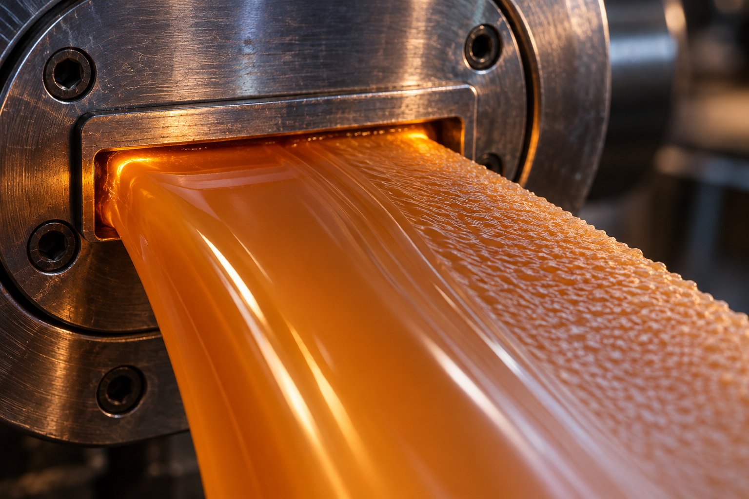
Surface Defects from Melt Fracture to Discoloration
Surface quality defects are the most immediately visible category of extrusion failures. A customer never needs a micrometer or a pressure chart to spot rough texture, streaking, or discoloration on a finished profile. These defects trigger rejections faster than almost any dimensional issue, yet their root causes span a wide range of mechanisms, from polymer flow instabilities deep inside the die to thermal degradation residue on screw flights. Understanding the science behind each defect type is what separates a targeted correction from a blind temperature adjustment that trades one problem for another.
Melt Fracture and Shark Skin Explained
If you have ever seen an extrudate emerge with a rough, irregular, almost torn-looking surface, you were likely looking at melt fracture. This flow instability occurs when the polymer melt exceeds its critical shear stress as it passes through the die land and exits the die opening. At that threshold, the melt can no longer maintain laminar flow, and the surface distorts into patterns ranging from subtle matteness to severe helical or chaotic roughness. Understanding melt fracture causes and solutions in extrusion starts with recognizing that the defect originates inside the die, not at the barrel or screw.
Shark skin is a related but distinct phenomenon. While melt fracture involves bulk flow instability across the entire melt stream, the shark skin defect in plastic extrusion is a surface-only distortion that develops right at the die lip. As the outer skin of the melt exits the die and suddenly loses the constraint of the die wall, it decelerates while the core continues to push forward. That velocity mismatch tears the surface into a fine, regular pattern of ridges, often described as resembling sharkskin or orange peel.
Both defects respond to a similar set of directional process adjustments, though for different underlying reasons:
- Reduce extrusion rate — Lowering throughput or screw speed decreases the shear rate at the die, dropping the melt below its critical stress threshold.
- Increase melt temperature moderately — A warmer melt has lower viscosity, which reduces the shear stress at any given flow rate. However, this lever has a hard ceiling. Push the temperature too high and you invite thermal degradation, the very trade-off explored later in this article.
- Apply a polymer processing aid (PPA) — Fluoropolymer-based processing aids migrate to the die wall and create a slip layer that reduces the stick-slip behavior responsible for shark skin. PPAs are especially effective for LLDPE and mLLDPE films.
- Widen the die land or increase the land length — A longer land area allows the melt to relax before exiting, reducing the velocity gradient at the surface. Die geometry changes are a more permanent solution when processing aids alone are not sufficient.
A critical warning applies here: operators who raise melt temperature aggressively to suppress melt fracture often create a new problem, thermal degradation, within the same production run. That cascading effect is one of the most common ways fixes backfire in extrusion, and it is why single-variable thinking fails.
Die Lines and How to Eliminate Them
Die lines are continuous longitudinal streaks on the extrudate surface that run in the machine direction. Unlike melt fracture, which stems from flow instability, die lines are almost always mechanical in origin. They result from physical damage to the die lip, contamination buildup in the die land area, or misalignment between die components.
Carbon buildup is one of the most frequent culprits. As industry experience confirms, die lines are quite often caused by carbonized polymer accumulating in the die land, the high-pressure zone just before the melt exits. The pressure drop across this area, typically in the range of 250 to 750 psi, means contamination cannot enter from the outside. The carbon originates from degraded polymer within the process itself, usually the result of excessive temperature, prolonged residence time, or both.
To understand how to fix die lines on extruded products, follow a systematic inspection and correction sequence:
- Inspect the die lips visually and with a fingertip. Even a small nick, burr, or scratch on the lip surface will imprint continuously onto the extrudate. If damage is found, the lip must be polished or lapped back to a mirror finish using progressively finer abrasive compounds.
- Check for plate-out and carbon deposits. Remove any buildup from the land area using brass tools or approved chemical solvents. Avoid steel scrapers, which can scratch the precision die surfaces and create new die lines.
- Verify die component alignment. A misaligned mandrel or a die body that has shifted due to thermal expansion or improper bolt torquing can create flow asymmetry that manifests as streaking. Re-torque die bolts in the manufacturer's recommended sequence after the die has reached operating temperature.
- Review temperature setpoints and calibration. In one documented case, a flexible packaging converter running an extrusion coating die at 675 degrees Fahrenheit experienced persistent die lines. Inspection revealed that the actual temperature was 30 degrees Fahrenheit hotter than the readout indicated due to uncalibrated controllers, accelerating degradation far beyond the expected rate. Correcting the temperature and calibrating the controllers eliminated the problem.
Prevention is always cheaper than correction. Maintaining calibrated temperature controllers, ensuring polymer flow never drops to near-zero rates where residence time spikes, and scheduling routine die disassembly and cleaning all reduce the risk of carbon-driven die lines before they appear.
Discoloration and Thermal Degradation at the Surface
Brown or yellow streaking, black specks, and a milky surface haze all fall under the umbrella of extrusion surface discoloration troubleshooting. Each points back to the same fundamental mechanism: thermal degradation in the extrusion process, where the polymer has been exposed to too much heat, too much time, or both.
The degradation pathway follows a predictable progression. Polymer subjected to excessive thermal energy first loses viscosity, then forms gels as molecular chains crosslink or break, and eventually carbonizes into hard dark particles. Think of it like a spill on the bottom of an oven: the residue gradually darkens from light brown to black carbon over repeated heating cycles. The same chemistry plays out on screw flights, in barrel dead zones, inside adapters, and along die flow channels.
Recognizing the specific symptom helps narrow the thermal cause:
- Yellow or brown streaks in the machine direction — Typically caused by degraded material hanging up in a flow channel dead spot or on a worn screw flight, then releasing intermittently into the melt stream.
- Black specks scattered randomly — Often traced to carbonized residue releasing from retention zones inside the barrel, adapter, or die. Specks that worsen after startup or restart suggest material that degraded during a hot hold or shutdown period.
- Black specks that increase steadily during a run — Point toward die build-up or adapter deposits accumulating and shedding progressively, rather than a one-time residue release.
- Surface haze or dullness without particulate contamination — Can indicate low-level thermal degradation that has not yet produced visible char but has altered the surface molecular structure enough to scatter light differently.
- Discoloration that tracks a specific material batch or regrind lot — Suggests external contamination or pre-degraded resin entering the process rather than degradation generated internally.
Proper purging procedures between material changes are one of the most effective defenses against thermal degradation carryover. When polymer remains in a hot barrel during a changeover, it degrades in every low-flow zone and hidden retention area. The next material to run through picks up those degraded fragments and carries them to the product surface. A thorough purge using an appropriate purge compound, timed correctly relative to the changeover, clears retention zones that the production resin alone cannot reach.
Equally important is reviewing shutdown and startup sequences. Lines that are shut down under full heat and left to soak degrade the stagnant melt inside the barrel and die. Reducing barrel temperatures before shutdown, purging before cooldown, and performing a controlled heat soak on restart all reduce the volume of degraded material that enters the product stream when the line comes back online.
Surface defects reveal what is happening to the polymer at its most vulnerable points: the die exit, the flow channel walls, and the interface between moving melt and static metal surfaces. Yet even when the surface looks perfect, the product can still fail specification for an entirely different reason, one rooted not in appearance but in geometry. Dimensional instability and pressure fluctuation carry their own diagnostic logic and demand a separate investigation path.
Fixing Dimensional Instability and Pressure Fluctuation
A profile with a flawless surface can still end up in the scrap bin. Wall thickness variation in extrusion, out-of-round tubing, pipe that drifts above or below its OD specification, and sheet that changes gauge across a roll — these dimensional failures are arguably more costly than surface defects because they are harder to catch visually and easier to miss until a downstream customer rejects an entire shipment. The root cause almost always connects back to pressure: melt pressure variation at the die translates directly into dimensional variation in the finished product.
How tight does pressure control need to be? That depends on product tolerances, but the relationship is sharper than many operators expect. SPE technical data indicates that plus or minus 5% melt pressure variation upstream of a sheet or film die can produce roughly 3 to 5% gauge variation in the product, depending on die geometry and land length. For a pipe or profile with tight wall-thickness specifications, even a 2 to 3% pressure swing can push parts out of tolerance. Dimensional instability in plastic extrusion is, at its core, a pressure stability problem — and pressure stability is a systems problem that can originate anywhere from the hopper to the puller.
Understanding Surging and Its Causes
Surging is the cyclic rise and fall of extruder output, and it is one of the most frustrating symptoms an operator can face. You see the melt pressure gauge oscillating rhythmically, the product dimensions waving in and out of spec, and the motor load pulsing in step. The frustration comes from the fact that extrusion surging causes and corrections span nearly every domain of the process. There is no single fix because there is no single cause.
At its simplest, surging means the screw is not delivering a constant volume of melt per revolution. That inconsistency can originate from the feed, from incomplete melting, from screw wear, or from a mismatch between screw speed and downstream resistance. The oscillation period itself is a diagnostic clue: cycles matching a vacuum receiver dump or feeder refill point to the material handling system, while cycles in the 1 to 5 minute range with no correlation to feeding events often indicate solids-conveying instability or solid-bed breakup inside the barrel.
A diagnostic decision tree keeps you from chasing the wrong variable. Work through it in order — skipping ahead almost always leads to wasted effort:
- Check feed consistency first. Is the hopper bridging? Is the feeder pulsing during refill? Does the surging period align with a receiver dump cycle? Pressure and motor load falling together then recovering is a strong indicator that the screw is periodically starved.
- Evaluate screw and barrel condition. Worn screw flights increase the clearance between flight tip and barrel wall, allowing melt to leak backward over the flights. This reduces the screw's pressure-generating capacity and creates unstable conveying. If output has been gradually declining over months at the same RPM, wear is a likely contributor.
- Review the barrel temperature profile. An incorrect temperature gradient, especially one that leaves unmelted solids entering the metering zone, creates surging as solid chunks intermittently break free from the melt bed. Recent experimental work confirms that solid-bed breakup frequency changes with operating conditions, making it a legitimate mechanism when feed, temperature, and instrumentation have already been verified.
- Assess screw RPM relative to the process window. Some screw designs become unstable above a certain speed because the solids-conveying capacity cannot keep up with the metering demand. If surging appears or worsens only at higher throughput, you may be operating beyond the stable melting envelope of the current screw geometry.
A practical rule from experienced process engineers: if changing screw speed shifts the surging frequency but does not eliminate it, the cause is likely inside the barrel. If the surging disappears entirely at lower speed, you are hitting a throughput ceiling set by the screw design, feed system, or both.
Pressure Fluctuation Diagnosis and Correction
Melt pressure fluctuation troubleshooting requires more than watching a single number on the HMI. As one diagnostic resource emphasizes, the first questions should always be: where is pressure measured, what shape does the trend make, and what else moves at the same time? A slowly rising pressure tells a completely different story than a cyclic sawtooth or a random spike.
Here is a structured approach to reading and correcting pressure instability:
- Ensure consistent feed rate. A gravimetric feeder that measures actual mass flow eliminates the bulk-density errors inherent in volumetric systems. If your pressure cycle aligns with feeder refill events, the correction belongs upstream of the extruder, not in the barrel temperature profile.
- Verify screw and barrel wear are within tolerance. Measure barrel bore diameter and screw flight OD at multiple points. Compare against the manufacturer's wear limits. Gradually increasing motor load at the same RPM, combined with declining output, is the classic wear signature.
- Optimize the barrel temperature profile to ensure complete melting before the metering zone. The metering zone should receive fully molten, thermally homogeneous polymer. If unmelts persist into this section, the compression zone temperatures may be too low or the screw geometry may not be generating sufficient shear for the resin being processed.
- Check for screen pack blinding. A progressively loading screen pack raises upstream pressure while reducing effective die-inlet pressure. The differential pressure across the screen — not just the absolute number at one location — is what reveals filter loading. Industry data identifies screen pack saturation as the most common cause of melt pressure instability in continuous production, producing a characteristic asymmetric cycle where pressure rises slowly over the screen life then drops sharply at each screen change.
One detail that many operators overlook: a pressure trace that looks noisy may not represent a real process disturbance at all. Damaged transducer tips, plugged sensing ports, electrical interference, and incorrect signal scaling can all create convincing but misleading pressure trends. Before tearing into the process, verify that a second pressure point or independent process variable confirms what the suspect transducer is reporting.
Downstream Causes of Dimensional Problems
Here is the scenario that catches even careful troubleshooters off guard: melt pressure at the die is rock-steady, yet the finished product still drifts out of specification. When pressure is stable but dimensions move, the cause lives downstream of the die — in the cooling, calibration, pulling, or cutting equipment.
These downstream contributors to dimensional instability are among the most influential yet overlooked variables in profile extrusion quality:
- Puller speed mismatch — A puller running too fast stretches the still-pliable extrudate, reducing wall thickness and OD. Too slow, and the product compresses, thickening walls and increasing diameter. Even small puller speed drifts — caused by belt wear, servo tuning errors, or inconsistent nip pressure — create periodic dimensional waves along the product length.
- Cooling bath temperature inconsistency — Uneven water temperature in a spray tank or immersion bath produces differential shrinkage. One side of a profile cools faster, contracts more, and the part bows or twists. Seasonal variations in plant water supply temperature can shift cooling rates enough to move dimensions that were stable for months.
- Vacuum calibration tank pressure variation — For pipe and profile, the vacuum sizing tank pulls the hot extrudate against a calibration sleeve to set external dimensions. If vacuum fluctuates — from a leaking seal, an undersized pump, or water level variation — the product alternates between being properly sized and undersized.
- Cutter synchronization failures — When the cutter does not match line speed precisely, cut lengths vary. More subtly, the cutter mechanism's clamping action can momentarily slow or distort the product at the cut point, creating a localized dimensional anomaly that repeats at every cut interval.
The following table helps distinguish whether a dimensional problem originates upstream in the melt delivery system or downstream in the forming and handling equipment:
| Dimensional Symptom | Upstream (Melt Delivery) Probable Cause | Downstream (Post-Die) Probable Cause |
|---|---|---|
| Wall thickness varies cyclically along length | Melt pressure surging from feed inconsistency, screw wear, or screen pack loading | Puller speed fluctuation or vacuum calibration pressure cycling |
| OD or width gradually drifts in one direction over a run | Screen pack loading progressively reducing die-inlet pressure | Cooling water temperature creeping due to ambient changes or chiller drift |
| Ovality or cross-section distortion | Uneven melt temperature or flow distribution in the die | Non-uniform cooling around the circumference, misaligned calibration tooling, or product sagging before solidification |
| Thin spots on one side only | Off-center mandrel or die lip gap asymmetry | One-sided cooling from a blocked spray nozzle or uneven air flow |
| Cut length variation | Rarely upstream unless extreme surging changes line speed | Cutter encoder misalignment, belt slip, or synchronization logic error |
| Surface marks at regular intervals unrelated to surging | Unlikely if melt pressure is stable | Puller belt marks, nip roll impressions, or cutter clamp distortion at each cut cycle |
The diagnostic key is correlation. Trend pressure, puller speed, vacuum level, cooling water temperature, and product dimensions on the same time base. If pressure holds flat while dimensions move, stop looking upstream and diagnose the downstream equipment. Conversely, if dimensions track pressure variation perfectly, the fix belongs in the melt delivery system.
Dimensional stability and pressure control are universal concerns across every type of extrusion — pipe, profile, sheet, tubing. But one category of extrusion amplifies these challenges to an extreme degree: thin film. When wall thickness is measured in microns instead of millimeters, the margin for error shrinks dramatically, and problems invisible in heavier-gauge products suddenly become impossible to ignore.
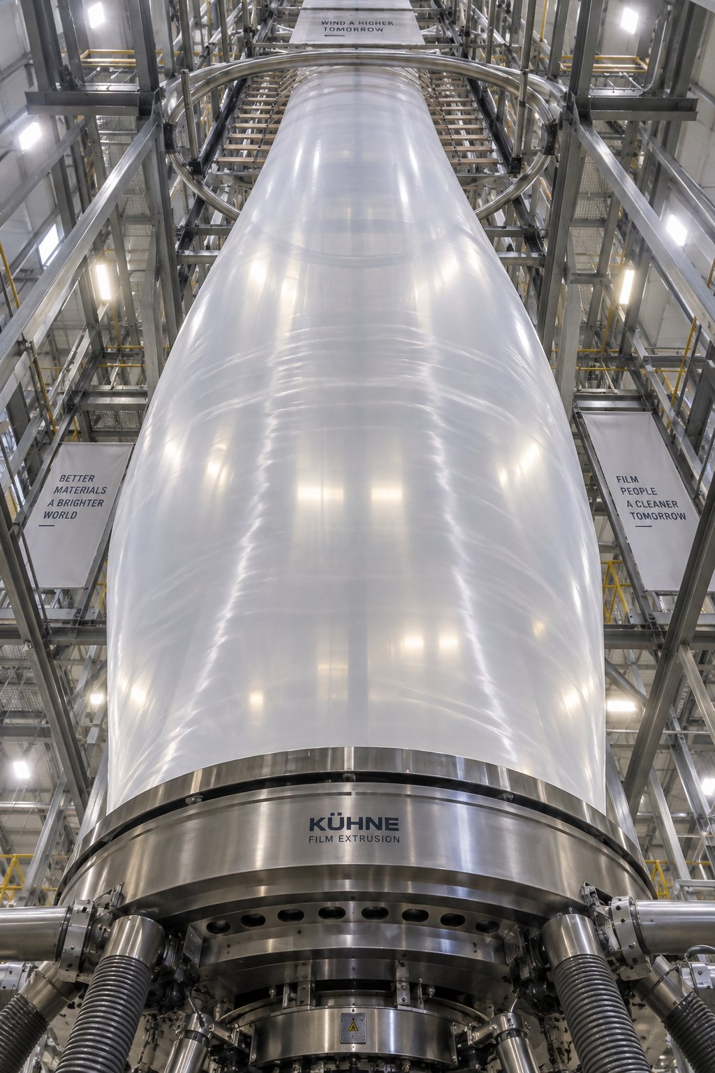
Blown Film and Thin Film Troubleshooting Strategies
A pipe extruder running with 2% wall thickness variation might still ship product within specification. A blown film line with the same 2% variation produces rolls that fail gauge requirements, jam converting equipment, and generate customer complaints. Film extrusion operates at the razor edge of process control, where every upstream inconsistency — feed fluctuation, melt temperature drift, pressure pulsation — translates directly into a visible or measurable defect. That is precisely why blown film extrusion problems and solutions deserve dedicated attention beyond general troubleshooting principles.
The physics are straightforward: when your product is measured in microns rather than millimeters, the ratio of process noise to product dimension grows enormously. A pressure swing that creates an imperceptible bump on a thick-wall profile produces a clearly measurable gauge band on a 25-micron film. Understanding this amplification effect changes how you prioritize maintenance, set process tolerances, and investigate defects on film lines.
Common Blown Film Extrusion Defects and Root Causes
Blown film production threads molten polymer through an annular die, inflates it into a bubble with internal air pressure, cools it with an external air ring, and collapses it through nip rollers before winding. Each stage introduces its own failure modes, and as Swallow Machinery's technical guidance emphasizes, these variables do not operate in isolation — a change in one parameter often impacts others, making process optimization a careful balancing act.
Three equipment elements exert the most influence over film quality: die gap uniformity, air ring balance, and frost line height management. Die gap uniformity controls thickness distribution around the bubble circumference. Even a few thousandths of an inch variation at the die lip creates a heavy and light band that spirals up the bubble and repeats across the lay-flat width. Air ring balance determines how evenly cooling air contacts the bubble surface. An imbalanced air ring cools one side faster, causing the bubble to lean, shift, or oscillate. Frost line height — the point where the melt transitions from transparent to opaque — reflects the balance between cooling rate, blow-up ratio, and haul-off speed. An unstable or uneven frost line is often the first visual clue that something upstream has changed.
Here are the most frequent blown film defects paired with their primary corrective actions:
- Gauge variation around the bubble — Check die lip gap uniformity using feeler gauges or an automated die profiling system. Adjust die bolts in small, sequential increments. Verify air ring concentricity relative to the die. Film gauge variation troubleshooting almost always starts at the die and air ring before looking anywhere else.
- Bubble instability and tear-offs — Bubble instability causes in blown film range from inconsistent air pressure and uneven cooling air flow to die imperfections and environmental drafts. Stabilize internal bubble pressure with a reliable IBC system, ensure the air ring delivers uniform flow, and shield the bubble from cross-drafts in the plant. Persistent tear-offs at a consistent circumferential position often point to a die lip defect or a localized hot spot in the air ring.
- Film haze or gels — Haze frequently traces to inadequate cooling that allows crystallization to occur too slowly, reducing optical clarity. Gels typically result from degraded material or contamination in the melt, not from the film-forming process itself. Increasing cooling air velocity and ensuring clean material handling address the two causes independently.
- Poor optical properties (low gloss, cloudiness) — Melt temperature that is too low produces a rough surface microstructure that scatters light. Conversely, melt temperature that is too high risks degradation, which also reduces clarity. The sweet spot is material-specific and narrow, particularly for LLDPE and metallocene polyethylenes.
- Die lines on film — Carbon buildup or lip damage that would be barely noticeable on a thick profile becomes strikingly obvious on thin film. Regular die cleaning and careful lip maintenance are non-negotiable on film lines.
Thin Film Troubleshooting Essentials
Thin-gauge extrusion, whether blown or cast, introduces a set of defects that do not appear at heavier gauges. The product is mechanically fragile between the die exit and the winding station, and even minor disturbances create defects that propagate through the entire roll.
Web breaks are the most disruptive. A web break halts production, generates scrap, and requires operator intervention to rethread the line. Common triggers include gels or contaminants that create a localized weak point, excessive draw ratio that exceeds the melt's elongational strength, and uneven cooling that produces thin bands susceptible to tearing under tension. Reducing these thin film extrusion defects and fixes often means tightening upstream melt quality rather than adjusting downstream line speed alone.
Wrinkles from uneven cooling appear when one area of the web cools and contracts faster than its neighboring region. The differential shrinkage buckles the film, and once a wrinkle forms, nip rollers lock it in permanently. Cast film lines are particularly vulnerable because cooling roll temperature uniformity directly determines flatness. Even a few degrees of variation across the roll face produces visible wrinkles.
Edge curl develops when the film edges cool at a different rate than the center, typically faster due to their greater surface-area-to-volume ratio. The edges contract more, curling inward or outward depending on the cooling geometry. Adjusting edge trim positions, fine-tuning air knife placement, or adding edge heating elements can counteract the differential.
Draw resonance is a periodic, self-sustaining oscillation in the film width and thickness that occurs at certain combinations of draw ratio and cooling rate. You will notice the film rhythmically narrowing and widening between the die and the first contact point. Lowering the draw ratio, increasing cooling intensity, or adjusting the air gap distance typically suppresses the resonance. The interaction between line speed, nip roll pressure, and cooling roll temperature makes draw resonance a multi-variable problem that rarely responds to a single adjustment.
Maintenance Practices Specific to Film Lines
Film extrusion magnifies every inconsistency that heavier-gauge processes can tolerate. That reality places an outsized premium on preventive maintenance — small oversights that a pipe line absorbs without consequence will shut down a film line or send reject rolls to the warehouse.
Die bolt tightening sequences deserve more attention than they typically receive. Die bolts expand and shift as the die heats to operating temperature. Tightening them cold, then never re-torquing at temperature, allows the die gap to drift as thermal expansion progresses. Best practice is to torque die bolts in a star pattern at operating temperature, using a calibrated torque wrench, and re-checking after the first hour of production. This single discipline eliminates a surprising proportion of gauge variation complaints.
Air ring cleaning schedules prevent the gradual accumulation of polymer fume condensate, dust, and volatiles on air ring surfaces and distribution channels. A partially clogged air ring delivers uneven cooling even though the blower is running at the correct speed. Preventive maintenance strategies for blown film recommend weekly inspection of air ring passages and monthly deep cleaning to maintain uniform airflow distribution.
Regular die profiling — measuring the actual film thickness around the circumference and mapping it to die bolt positions — closes the loop between maintenance activity and product quality. Manual profiling with a micrometer at marked positions around the lay-flat works for periodic checks, while automated thickness gauges provide continuous real-time feedback. Either way, the data drives targeted die bolt adjustments rather than guesswork.
Film extrusion serves as a diagnostic amplifier. Problems invisible in thicker products — minor pressure pulsations, slight temperature gradients, small die lip imperfections — become glaringly obvious when the product is only microns thick. A well-maintained film line is not just good practice; it is the only way to produce salable product consistently.
Maintenance discipline and process control tighten the window against defects, but they operate within the constraints set by the material itself. The same defect on two different polymers may demand completely different corrective actions — a reality that generic troubleshooting guides consistently overlook and one that demands a polymer-by-polymer perspective.
Material-Specific Extrusion Challenges Across Common Polymers
A rough surface on a PVC profile and a rough surface on an HDPE pipe may look identical to the naked eye, yet the corrective action for each is fundamentally different. Raise the melt temperature to smooth out the PVC, and you risk triggering thermal degradation within seconds. Apply the same temperature increase to the HDPE, and the surface clears up without consequence. That divergence is not a minor footnote — it is the reason generic troubleshooting advice fails in real plants running real materials. Material-specific extrusion processing tips are not optional refinements; they are prerequisites for getting the fix right the first time.
Every polymer carries its own processing personality: a unique combination of thermal sensitivity, shear response, moisture tolerance, and crystallization behavior that dictates how it reacts inside the extruder. Ignoring that personality means applying a correction designed for one resin to a problem caused by another, which is exactly how fixes backfire.
PVC Extrusion Challenges and Parameter Guidance
PVC stands apart from virtually every other commodity thermoplastic because of its narrow processing window and extreme sensitivity to both heat and shear. Unlike polyethylene or polypropylene, PVC does not flow as a low-viscosity melt. Instead, it transitions into what is best described as a gelled, elastic-plastic state — a gelation behavior that affects melt pressure, torque, surface finish, and stabilizer consumption simultaneously. Understanding PVC extrusion problems and solutions starts with accepting that this material punishes imprecision more harshly than any polyolefin.
Thermal degradation is the dominant concern. When PVC is exposed to excessive temperature or prolonged residence time, it releases hydrochloric acid (HCl) and discolors rapidly — first yellowing, then browning, then charring to black. The degradation window can be startlingly narrow: just 5 to 10 degrees Celsius above optimal processing temperature may be enough to initiate decomposition, particularly if the stabilizer package is insufficient or unevenly dispersed.
Key PVC-specific challenges and their corrective directions include:
- Plate-out — A waxy or chalky deposit that accumulates on die surfaces, calibration tooling, and downstream equipment. Plate-out results from migration of lubricants, stabilizers, or other additives to the surface of the melt. Rebalancing the internal-to-external lubricant ratio in the compound formulation is the primary correction. Cleaning die surfaces regularly prevents buildup from reaching levels that imprint on the product.
- Thermal degradation indicators — Brown discoloration, burn marks, or black specks in PVC almost always trace to high temperature, excess shear, low stabilizer levels, or blocked venting. Torque monitoring is especially valuable with PVC because sudden torque spikes suggest poor lubrication or material contamination, both of which accelerate degradation.
- Surface roughness or shark skin texture — In PVC, this defect often responds to increasing external lubrication or raising die temperature slightly rather than increasing overall melt temperature. The distinction matters: raising barrel temperatures adds shear heat and residence-time risk, while a targeted die temperature increase affects only the final flow stage.
- Inadequate fusion (gelation) — PVC that has not gelled sufficiently produces weak, brittle extrudates with poor impact resistance. Insufficient barrel temperature, inadequate screw shear, or excess lubricant can all inhibit proper gelation. The corrective action involves finding the specific temperature-shear combination that achieves complete fusion without crossing the degradation threshold.
Screw design matters enormously for PVC. A low-shear screw with a moderate compression ratio — typically 1.3 to 1.6 — provides adequate melting and gelation while keeping shear-generated heat within safe limits. Ratios that are too high cause overheating and degradation. Twin-screw extruders, especially conical or parallel counter-rotating designs, are widely preferred for rigid PVC pipes and profiles precisely because they offer superior mixing with lower shear intensity than aggressive single-screw designs.
Polyolefin Troubleshooting for PE and PP
Polyethylenes and polypropylene sit at the opposite end of the processing-friendliness spectrum from PVC. Their broader thermal windows and greater tolerance for shear variation make them forgiving in many situations — but each polyolefin type introduces its own characteristic failure modes that demand targeted responses.
HDPE presents challenges rooted in its high crystallinity. When HDPE cools, its polymer chains pack into a dense, ordered crystalline structure, and that crystallization drives significant shrinkage. Pipes and profiles extruded from HDPE are prone to warpage, sink marks, and dimensional instability if cooling is not precisely managed. Rapid or uneven cooling locks in internal stresses that release later as distortion, especially in thick-walled products. An HDPE extrusion troubleshooting guide should emphasize cooling rate uniformity as the single most impactful variable for dimensional stability, followed closely by melt temperature control to ensure consistent crystallization kinetics from run to run.
HDPE also demands attention at the die. Its relatively high melt viscosity at typical processing shear rates makes it susceptible to melt fracture, particularly in high-output applications. Processing aids or die land modifications that would be unnecessary for LDPE become essential when pushing HDPE throughput toward the upper end of the screw's capacity.
LDPE, by contrast, offers a broader processing window thanks to its highly branched molecular architecture, which lowers crystallinity and reduces shrinkage-related defects. LDPE flows more easily at lower shear stresses and is less prone to melt fracture. However, its lower melt strength compared to HDPE makes it more susceptible to bubble instability in blown film and to sag in profile or sheet extrusion. Where HDPE problems tend to manifest as post-cooling dimensional issues, LDPE problems typically show up as melt-phase instabilities.
Polypropylene introduces a different vulnerability. PP is notably sensitive to oxidation at elevated temperatures, and it requires higher processing temperatures with a narrower processing window versus PE. Without adequate stabilization — typically a combination of antioxidants and thermal stabilizers — PP degrades through chain scission, which reduces melt viscosity progressively during the run. You will notice the melt flow index creeping upward, the product becoming increasingly brittle, and a faint odor developing. PP also has a higher shrinkage rate during cooling than PE, which can affect the dimensional accuracy of extruded parts, particularly in profile and sheet applications where tight tolerances are required.
A practical distinction for polyolefin troubleshooting: if your defect looks thermal (discoloration, embrittlement, odor), suspect oxidative degradation and check stabilization adequacy. If your defect looks dimensional (warpage, ovality, sink marks), suspect crystallization-related shrinkage and focus on cooling uniformity and rate.
Engineering Resins and Specialty Polymers
Engineering resin extrusion challenges differ qualitatively from commodity polymer issues. These materials demand stricter process discipline, more specialized equipment, and less tolerance for the shortcuts that polyolefins may forgive.
ABS (acrylonitrile butadiene styrene) is moisture-sensitive enough that undried material produces surface splay, silver streaking, and bubble formation in the extrudate. Drying to below 0.05% moisture content before processing is not optional — it is the prerequisite for any ABS extrusion run. The butadiene rubber phase in ABS also makes it susceptible to yellowing from thermal degradation, particularly at temperatures above its recommended range or with excessive residence time. Keep barrel temperatures within the material data sheet range and minimize dead spots in the flow path.
Nylon (polyamide) takes moisture sensitivity to an extreme. Nylon extrusion moisture-related defects are among the most common complaints on lines processing PA6 or PA66. Nylon is hygroscopic enough to absorb several percent of its weight in atmospheric moisture if left exposed. That absorbed water acts as a plasticizer at low levels but generates steam bubbles, splay marks, and severe surface defects at processing temperatures if the moisture exceeds approximately 0.1 to 0.2% depending on the grade. Desiccant drying at the correct temperature for the correct duration is mandatory, and the dried material must be fed from a sealed hopper or directly from the dryer to prevent re-absorption. Even 20 to 30 minutes of exposure to humid plant air can push nylon moisture content back above the safe threshold.
TPE and TPU (thermoplastic elastomers and polyurethanes) are shear-sensitive materials that behave very differently from rigid thermoplastics inside the extruder. High shear rates degrade the soft-segment structure that gives these materials their elastomeric properties, leading to loss of elongation, hardness shifts, and surface roughness. Screw compression ratios must be lower than those used for rigid polymers — typically in the 2.0:1 to 2.5:1 range — and mixing sections should provide distributive mixing without excessive dispersive shear. Barrel temperatures need to be managed carefully because TPU is prone to sticking to metal surfaces at elevated temperatures, promoting degradation buildup and black speck formation.
The following table consolidates the critical processing concern, typical defect, and recommended corrective action for five common resin families. Treat it as a quick-reference starting point when a defect appears on a specific material:
| Polymer Type | Critical Processing Concern | Typical Defect Observed | Recommended Corrective Action |
|---|---|---|---|
| PVC | Extremely narrow thermal window; shear sensitivity; requires precise lubricant balance | Brown/black discoloration, plate-out on die surfaces, brittle product from inadequate gelation | Use low-shear screw design (compression ratio 1.3-1.6); maintain tight temperature control; verify stabilizer and lubricant levels in compound; monitor torque for degradation spikes |
| HDPE | High crystallinity drives significant shrinkage; susceptible to melt fracture at high output rates | Warpage, sink marks, dimensional instability, rough surface at high throughput | Ensure uniform cooling rate and temperature around entire product circumference; consider processing aids or wider die land for melt fracture; control melt temperature for consistent crystallization |
| PP | Oxidation sensitivity at elevated temperatures; narrower processing window than PE; high shrinkage | Progressive embrittlement, increasing melt flow during run, faint odor, dimensional drift from shrinkage | Confirm adequate antioxidant stabilization in resin; avoid excessive barrel temperatures; minimize residence time; optimize cooling for shrinkage compensation |
| ABS | Moisture absorption causes surface defects; butadiene phase yellows from thermal exposure | Silver streaking or splay, surface bubbles, yellowing or discoloration | Dry to below 0.05% moisture before processing; keep barrel temperatures within data sheet range; minimize dead spots and residence time in flow path |
| Nylon (PA6/PA66) | Extreme hygroscopic behavior; absorbed moisture generates steam at processing temperatures | Bubble formation, splay marks, severe surface roughness, loss of mechanical properties | Desiccant-dry to below 0.1-0.2% moisture; feed from sealed system directly from dryer; prevent re-absorption during handling; use vented barrel if available |
| TPE/TPU | Shear sensitivity degrades elastomeric properties; prone to sticking and degradation buildup on metal surfaces | Loss of elongation, hardness change, surface roughness, black specks from degraded buildup | Use low compression ratio screw (2.0-2.5:1); favor distributive over dispersive mixing; manage barrel temperatures to prevent sticking; purge thoroughly between runs |
One theme runs through every row of that table: screw geometry must match the material. A general-purpose screw that delivers acceptable results with LDPE may cause severe degradation with PVC, insufficient melting with HDPE, or excessive shear damage with TPU. The notion that one screw fits all resins is one of the most persistent and costly misconceptions in extrusion. When operators exhaust every process parameter adjustment without resolving a persistent defect, the root cause often turns out to be a fundamental mismatch between the screw design and the material being processed — a hardware problem that no software-level tweak can overcome.
That recognition raises a deeper question. If certain defects resist every temperature, speed, and pressure adjustment you can make, how do you determine whether the problem lives in the process settings or in the equipment itself? The answer lies in understanding how screw and barrel design choices create — or eliminate — the conditions for persistent extrusion failures.
How to Avoid Creating New Extrusion Problems When Fixing Existing Ones
Every experienced operator has lived through this scenario: you raise melt temperature to clear up a rough surface, and twenty minutes later a quality inspector flags yellow discoloration on the same product. You have not solved a problem — you have traded it. The cascading effects of extrusion parameter changes are the single most underappreciated source of chronic instability in extrusion plants. Each process variable is connected to every other variable through the physics of polymer flow, heat transfer, and mechanical energy input. Pull one lever without understanding those connections, and you reliably push the process into a different failure mode.
How Temperature Adjustments Create Cascading Effects
Temperature is the lever operators reach for most often because it feels intuitive and responds quickly. Yet temperature changes ripple through the entire melt-delivery system in ways that frequently surprise.
Consider a concrete example. Melt fracture appears on an HDPE pipe — the surface shows the characteristic rough, irregular texture of polymer that has exceeded its critical shear stress at the die. The textbook correction is to raise melt temperature, which lowers viscosity and reduces shear stress at any given throughput. The operator bumps barrel zone temperatures by 10 degrees Celsius. The melt fracture clears. But within the hour, faint brown streaks appear in the product. The higher temperature has pushed the polymer closer to its degradation threshold, and material lingering in low-flow zones inside the adapter and die now has enough thermal energy to begin breaking down. Fixing one defect created another.
The reverse scenario is equally common. A plant running PVC notices early discoloration and correctly lowers barrel temperatures to reduce thermal exposure. The degradation symptoms improve, but now the melt arrives at the die partially unmelted. Surface roughness returns — not from melt fracture this time, but from solid polymer fragments that never fully fused. The operator faces a frustrating choice: tolerate some discoloration or tolerate some roughness, because the available temperature range is not wide enough to avoid both.
Screw speed adjustments create their own cascading chains. Increasing RPM to boost output raises shear heat inside the barrel, effectively adding an uncontrolled temperature increase that the barrel cooling system may not fully compensate. As experienced process engineers observe, raising barrel temperatures may reduce torque temporarily while increasing degradation risk, and slowing the screw may calm pressure swings while hurting mixing quality or downstream capacity. Every adjustment carries a secondary cost — the question is whether that cost pushes you outside your acceptable operating envelope.
Finding the Optimal Process Window
The concept of a process window reframes how you think about extrusion process window optimization. Instead of searching for a single "perfect" set of parameters, imagine a multi-dimensional space where each axis represents a controllable variable — melt temperature, screw speed, feed rate, cooling intensity, puller speed. Somewhere in that space sits a region where all product specifications are met simultaneously: surfaces are smooth, dimensions are within tolerance, there is no degradation, and output meets the production target. That region is your process window.
Every parameter adjustment moves your operating point within that space. Some moves are safe — they stay well inside the acceptable region. Others push you toward an edge, where one more small shift triggers a new defect. The dangerous adjustments are the ones that seem to fix the visible problem while quietly sliding the process to the boundary of a different failure mode. You do not know you are at the edge until you step off it.
What makes this framework powerful is the recognition that some actions expand the window while others shrink it. Proper material drying expands the window by removing moisture as a variable. Consistent feeding expands it by eliminating pressure surges. Worn screw flights shrink it by reducing the screw's ability to generate stable pressure across a range of conditions. Contaminated die flow channels shrink it by introducing dead spots where degradation can initiate at lower temperatures than a clean system would tolerate.
Successful extrusion troubleshooting means expanding the process window, not chasing individual symptoms. Every corrective action should be evaluated not just by whether it fixes today's defect, but by whether it widens or narrows the margin against tomorrow's.
This perspective explains why how to avoid creating new extrusion problems is ultimately a maintenance question as much as a process-setting question. A well-maintained extruder inherently has a wider process window than a worn or contaminated one, because every mechanical deficiency — worn flights, fouled cooling channels, degraded heater bands, carbon-lined flow paths — subtracts operating margin that the operator must compensate for with tighter parameter control.
Preventive Maintenance as a Problem-Prevention Strategy
Reactive maintenance waits for the defect to appear and then scrambles to find the cause. Preventive maintenance eliminates the conditions that produce defects before they ever reach the product. The difference in cost and disruption is enormous: a planned barrel inspection during a scheduled changeover takes a fraction of the time and expense of an emergency screw pull triggered by a contamination crisis mid-run.
Proper startup sequences are a maintenance discipline, not just an operating procedure. Bringing an extruder to full operating temperature too quickly creates thermal gradients between the barrel's inner surface and its outer shell. Those gradients stress the barrel metallurgically and, more immediately, carbonize any residual polymer left from the previous run before it has a chance to soften and purge cleanly. A gradual heat soak — bringing each zone up in stages and holding at intermediate temperatures — prevents thermal shock, reduces carbonization, and extends barrel life.
Shutdown purging procedures are equally critical. As preventive maintenance research confirms, degraded polymers, carbon buildup, trapped color residue, and burned material accumulate inside barrels, screws, and extrusion components over time. Eventually, production quality drops, contamination increases, and machines require labor-intensive teardown. Purging with an appropriate compound before shutdown — rather than letting production resin sit in a hot barrel — clears retention zones and prevents the hardened contamination that drives unplanned screw pulls. A proper purge before any extended idle period is one of the highest-return maintenance investments a plant can make.
Die cleaning and inspection protocols prevent the slow accumulation of plate-out, carbon deposits, and surface damage that narrow the process window over days and weeks. Scheduled disassembly, cleaning with brass tools, and surface inspection under magnification catch developing problems while they are still minor maintenance tasks rather than production-stopping emergencies.
Screen changer maintenance ensures that filter media changes do not introduce their own pressure disturbances. Worn seals, sticking slide plates, and improperly seated screen packs all create the pressure fluctuations that operators then try to correct with process adjustments — adjustments that mask the real problem while introducing new variables.
The following extruder preventive maintenance schedule organizes these tasks by frequency. Adapt the specifics to your equipment, materials, and production intensity, but maintain the cadence:
- Daily: Verify barrel zone temperatures match setpoints and check for heater or thermocouple faults. Confirm cooling water flow rates at the feed throat and barrel zones. Inspect the hopper for bridging or contamination. Record melt pressure, motor amperage, and output at standard conditions as baseline trend data.
- Weekly: Inspect die lips for buildup, nicks, or wear. Clean screen changer seals and verify smooth operation. Check downstream equipment calibration — puller speed, vacuum levels, cooling bath temperatures. Review trend data for gradual drift in pressure, amperage, or output that may signal developing wear.
- Monthly: Perform a thorough die disassembly, cleaning, and inspection. Verify barrel zone heater resistance and thermocouple accuracy. Inspect feed throat for polymer buildup or wear. Run a complete purge cycle with a mechanical purging compound to clear retention zones. Check drive belt tension, gearbox oil level, and motor condition.
- Quarterly: Measure barrel bore diameter at multiple points along the length and compare against wear limits. Inspect screw flight OD, root diameter, and surface condition for wear, scoring, or buildup. Evaluate screen changer components for seal wear and plate condition. Review and calibrate all pressure transducers, temperature controllers, and downstream instrumentation. Document findings and compare against previous quarterly records to identify wear trends before they cause process failures.
Plants that follow a disciplined preventive schedule consistently report fewer emergency shutdowns, lower scrap rates, and — perhaps most importantly — wider process windows that give operators more room to adjust for normal production variability without falling off a quality cliff.
Yet even the most rigorous maintenance program cannot compensate for a fundamental equipment mismatch. When screw geometry does not suit the material, when compression ratios fight the polymer's melting behavior, or when wear has eroded the mechanical foundation of the process, the root cause lives in the hardware itself — and no combination of parameter adjustments or maintenance intervals can fully restore performance.
How Screw Barrel Design Solves Persistent Extrusion Failures
Picture this: you have optimized every temperature zone, verified feed consistency, cleaned the die twice, and followed the diagnostic framework from feed throat to puller. The defect persists. Output still drifts. Melt quality remains inconsistent. At some point, the honest conclusion is that the problem is not what you are doing with the equipment — it is the equipment itself. Screw and barrel design choices create or eliminate the mechanical conditions for stable extrusion, and when those choices do not match the material or application, no amount of process parameter tuning can compensate.
This is the territory where extrusion problems and solutions shift from process engineering to hardware engineering. A screw designed for one polymer family may be fundamentally incapable of producing acceptable melt quality with another. A barrel worn beyond tolerance robs the screw of the pressure-building capacity it was designed to deliver. Recognizing when you have crossed from a process problem into an equipment problem saves weeks of frustrating trial-and-error adjustments that never quite work.
Compression Ratio and L/D Ratio Selection
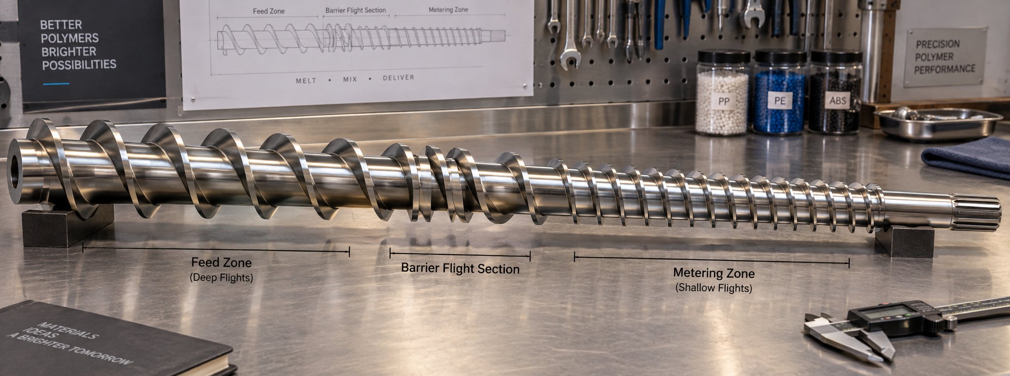
The compression ratio of an extruder screw — the ratio of the feed zone channel depth to the metering zone channel depth — determines how aggressively the screw compacts and melts the polymer. Getting this ratio right is one of the most consequential decisions in extruder screw compression ratio selection, and getting it wrong produces problems that mimic process faults but resist every process-level fix.
When the compression ratio is too high for the material, the screw forces the polymer through an excessively tight channel transition. The result is excessive shear heating, localized overheating in the compression zone, and accelerated degradation — particularly dangerous for shear-sensitive materials like PVC or TPU. Operators observe rising melt temperature despite no change in barrel setpoints, discoloration that worsens at higher screw speeds, and in severe cases, audible popping or surging as overpressured material slips backward over the flights. Lowering barrel temperatures may mask the symptom temporarily, but the root cause is mechanical: the screw geometry itself is generating more shear energy than the polymer can absorb without degrading.
When the compression ratio is too low, the opposite failure mode emerges. The screw does not compact and shear the solid polymer bed aggressively enough to complete melting before the metering zone. Unmelted particles — sometimes called "unmelts" or "gels" depending on their downstream appearance — survive into the metering section and arrive at the die as solid inclusions embedded in the melt stream. The product shows surface roughness, poor mechanical properties, and inconsistent dimensions. Raising barrel temperatures can partially compensate by adding conductive heat, but the melt homogeneity that proper compressive melting provides cannot be replicated by barrel heaters alone.
The L/D ratio (length-to-diameter ratio) of the screw governs how much total processing the polymer experiences. A longer screw provides more residence time for melting, mixing, and thermal homogenization, but it also increases the total shear history and thermal exposure. As NC State Extension research on screw profile design emphasizes, the arrangement and length of screw elements must be matched to the material's flow properties, because every polymer responds differently to heat and shear conditions. A typical single-screw extruder for polyolefins runs at 24:1 to 30:1 L/D, while PVC processing often uses shorter screws (20:1 to 24:1) to limit residence time and thermal exposure. Engineering resins that require thorough drying and devolatilization may benefit from 30:1 or longer L/D ratios with vented barrel sections.
A practical diagnostic clue: if your defect improves at lower screw speed but worsens at higher speed — even with barrel temperatures held constant — the screw is likely generating more shear energy than the material can tolerate. That points directly to a compression ratio or L/D mismatch rather than a temperature control problem.
Mixing Sections and Barrier Screw Designs
Even with the correct compression ratio and L/D, a standard metering screw may not deliver adequate melt quality for demanding applications. Gels, color streaks, unmelts, and poor additive dispersion all point to insufficient mixing — a limitation that mixing elements and barrier screw designs specifically address.
Mixing in extrusion occurs through two distinct mechanisms. Distributive mixing spreads the dispersed phase — whether that is colorant, additive, or a different polymer — evenly throughout the melt without necessarily breaking down particle size. Dispersive mixing applies high shear stress to break apart agglomerates, gels, or undispersed particles into smaller units. The geometry of the mixing element determines which type of mixing dominates. As twin-screw extrusion research from NC State's screw functionality publication details, wider kneading elements promote dispersive mixing, while narrow kneading elements contribute toward distributive mixing — and the arrangement, stagger angle, and conveying direction of these elements further tune the intensity.
For single-screw extruders, common mixing section designs include:
- Maddock (Union Carbide) mixers — A fluted barrier section that forces the melt through narrow gaps, providing strong dispersive action. Effective at trapping and breaking up unmelts or gels before they reach the die.
- Pineapple mixers — Provide distributive mixing by repeatedly splitting and recombining the melt stream. Excellent for color dispersion and blending but less effective at breaking apart hard agglomerates.
- Cavity transfer mixers — Combine elements of both distributive and dispersive action by transferring material between opposing cavities on the screw and a matching barrel sleeve.
Barrier screw designs take a fundamentally different approach to improving melt quality. A barrier screw introduces a secondary flight — the barrier flight — that physically separates the solid bed from the melt pool within the screw channel. Molten polymer passes over the barrier flight into a dedicated melt channel, while solids remain confined until they are fully melted. This separation accomplishes two things simultaneously: it prevents solid fragments from bypassing the melting zone and reaching the metering section, and it improves melting efficiency by ensuring the solid bed maintains continuous contact with the hot barrel wall. The result is barrier screw design for better melt quality — fewer unmelts, tighter melt temperature uniformity, and more consistent output.
The practical impact is significant. Plants that switch from a conventional metering screw to a properly designed barrier screw for the same material often see immediate improvements in surface quality, reduced gel counts, and narrower pressure variation — without changing any process setpoint. The hardware change expands the process window in exactly the way that chapter's earlier discussion described.
When Equipment Support Makes the Difference
Here is the uncomfortable truth that many troubleshooting guides avoid: a substantial portion of persistent extrusion failures trace back to screw and barrel condition or design mismatch rather than process settings. Operators spend days or weeks adjusting temperatures, speeds, and feed rates because those are the variables they can control in real time. But when the screw geometry does not suit the material, or when wear has degraded the mechanical precision of the system, those adjustments are compensating for a hardware deficit that will never fully resolve.
Recognizing screw and barrel wear signs in extrusion — and distinguishing them from process-related symptoms — is a critical diagnostic skill. The following indicators suggest that your problem is equipment-related:
- Gradual output decline over weeks or months at the same screw speed, barrel temperatures, and material — the classic signature of progressive flight wear increasing clearance and reducing conveying efficiency.
- Increasing motor load at the same RPM without a material change, indicating that the screw is working harder to push less material forward as worn flights lose their pumping effectiveness.
- Visible screw flight wear — rounded flight tips, reduced flight OD compared to original specifications, or scoring on the flight land surfaces. As detailed screw maintenance guidance confirms, visible wear exceeding the manufacturer's specified tolerances on flight lands or channel depth is a clear replacement indicator.
- Rising melt temperature without any change in barrel setpoints, which means increased shear heating from degraded screw-barrel geometry rather than an external heat source.
- Poor melt quality (gels, unmelts, inconsistent color dispersion) that does not respond to temperature or speed adjustments — the mixing and melting capacity of the screw has been mechanically compromised.
- Increased energy consumption to achieve the same output, reflecting the efficiency loss that accompanies worn clearances, degraded flight geometry, or both.
When these signs accumulate, the decision shifts from "what process setting should I change?" to "does this screw and barrel need to be replaced, reground, or redesigned for the current material?" That question requires specialized knowledge — understanding which screw geometry matching for extrusion materials will solve the specific failure mode, whether a barrier design is warranted, what compression ratio suits the polymer, and whether the barrel bore is still within serviceable tolerance.
This is the point where many plants benefit from external expertise. When in-house troubleshooting consistently points to screw and barrel issues — output instability that tracks wear progression, melt-quality inconsistencies that resist process adjustment, pressure fluctuation tied to mechanical degradation — working with a supplier who understands the relationship between screw geometry and extrusion performance accelerates the path to resolution. NANHAIYA, for example, provides screw barrel support for extrusion plants, recycling operations, and processing teams dealing with exactly these hardware-rooted problems, offering both replacement components and guidance on screw geometry selection matched to specific materials and applications.
Knowing when to replace an extruder screw and barrel — rather than continuing to compensate with ever-tighter process parameter control — is ultimately a cost decision. A worn or mismatched screw forces operators into an artificially narrow process window, drives up scrap, increases energy consumption, and consumes engineering hours on troubleshooting that never reaches a permanent solution. A correctly specified replacement expands the process window, restores output capacity, and often pays for itself within weeks through reduced scrap and improved uptime. The most effective approach to extrusion problems and solutions recognizes that sustainable quality starts with the right hardware foundation — and builds process optimization on top of it, not in place of it.
Frequently Asked Questions About Extrusion Problems and Solutions
1. What are the most common extrusion problems in plastic manufacturing?
The most common extrusion problems include surface defects like melt fracture, shark skin, and die lines; dimensional instability such as wall thickness variation and ovality; output surging caused by feed inconsistency or screw wear; discoloration from thermal degradation; and pressure fluctuation at the die. Each of these issues can originate from one or more of four interacting domains: material properties, machine condition, die geometry, and process parameter settings. Rather than addressing symptoms in isolation, experienced operators use a systematic root-cause isolation process that starts at the feed zone and works downstream to pinpoint the true origin before making any adjustments.
2. How do you troubleshoot surging in an extruder?
Surging — the cyclic rise and fall of extruder output — requires a structured diagnostic approach. Start by checking feed consistency: hopper bridging, feeder refill pulses, or regrind blending issues are the most frequent upstream culprits. Next, evaluate screw and barrel wear, since worn flights increase clearance and reduce conveying stability. Then review the barrel temperature profile to ensure complete melting before the metering zone, as solid-bed breakup can generate rhythmic pressure oscillations. Finally, assess whether screw RPM exceeds the stable throughput envelope of the current screw design. If lowering speed eliminates surging, you may be hitting a capacity ceiling set by screw geometry or the feed system rather than a temperature problem.
3. Why does fixing one extrusion defect sometimes create a new one?
Extrusion process variables are interconnected through polymer flow physics, heat transfer, and mechanical energy input. Raising melt temperature to eliminate melt fracture, for example, lowers viscosity and clears the surface defect but simultaneously increases thermal exposure, which can trigger degradation and discoloration. Similarly, reducing temperature to prevent degradation may leave the polymer partially unmelted, causing surface roughness. This cascading effect is why experienced process engineers think in terms of a process window — a range of parameter combinations that satisfy all quality requirements simultaneously — rather than chasing single-variable fixes. Expanding that window through proper maintenance, consistent feeding, and correct screw geometry is more effective than repeatedly adjusting individual settings.
4. How do you know when an extruder screw and barrel need to be replaced?
Several indicators point to equipment wear rather than a process-setting problem. Watch for gradual output decline over weeks or months at constant screw speed and temperatures, increasing motor load at the same RPM without a material change, visible rounding or reduction in screw flight outside diameter, and rising melt temperature despite unchanged barrel setpoints. Poor melt quality — gels, unmelts, or inconsistent color dispersion — that does not respond to temperature or speed adjustments also signals that the screw's melting and mixing capacity has been mechanically compromised. When these signs accumulate, working with a specialized supplier like NANHAIYA for screw barrel assessment and replacement often resolves issues that months of process tweaking could not.
5. What role does material type play in extrusion troubleshooting?
Material type fundamentally changes how you diagnose and correct extrusion defects. The same visible symptom — rough surface texture, for instance — demands completely different corrective actions depending on the polymer. PVC has an extremely narrow thermal processing window where even a few degrees of excess temperature triggers degradation, while HDPE can tolerate broader temperature ranges but struggles with shrinkage-driven dimensional instability due to its high crystallinity. Hygroscopic resins like nylon require strict drying protocols because absorbed moisture generates steam bubbles at processing temperatures. Shear-sensitive materials such as TPE and TPU need low-compression-ratio screws to preserve their elastomeric properties. A general-purpose screw acceptable for polyethylene may cause severe degradation with PVC or inadequate melting with engineering resins, making screw geometry matching to material a critical but often overlooked factor.
Written by
Nanhaiya Technical Team
Zhoushan Nanhaiya Plastic Machinery Co., Ltd.
The Nanhaiya technical team supports screw and barrel manufacturing projects through application review, technical communication, custom manufacturing coordination, and production and quality control.
Discuss Your Application
Related Articles
More insights on screw barrel technology and plastics processing.
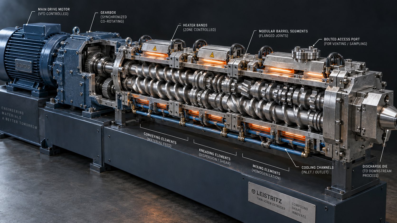
Co Rotating Twin Screw Extruder Parts: From Drive To Die Face
Oct 12, 2026
Complete guide to co rotating twin screw extruder parts — screw elements, kneading blocks, barrel segments, drive components, and material grades explained for sourcing and optimization.
Read Article
What Nobody Tells You About Screw Barrel For Plastic Machine Design
Oct 10, 2026
Learn how screw barrel for plastic machine design affects melt quality, throughput, and wear life. Covers geometry, resin matching, troubleshooting, and sourcing.
Read Article
Single Screw Extruder for Sheet: Stop Guessing, Start Specifying
Oct 9, 2026
Learn how to specify a single screw extruder for sheet production. Covers screw geometry, resin-specific processing, troubleshooting, and maintenance best practices.
Read ArticleLooking for something else?
Search by material, symptom or product and jump straight to the relevant page.
These are navigation suggestions based on keyword matching — not a quotation, not a delivery commitment, and not a substitute for engineering review. Final specification is confirmed by our engineers against your drawings and processed material.
Need help with screw barrel selection?
Share your machine model, processed material and application. Our team can help with pricing and technical support.