

What Is a Plastic Pipe Extruder and Why It Matters
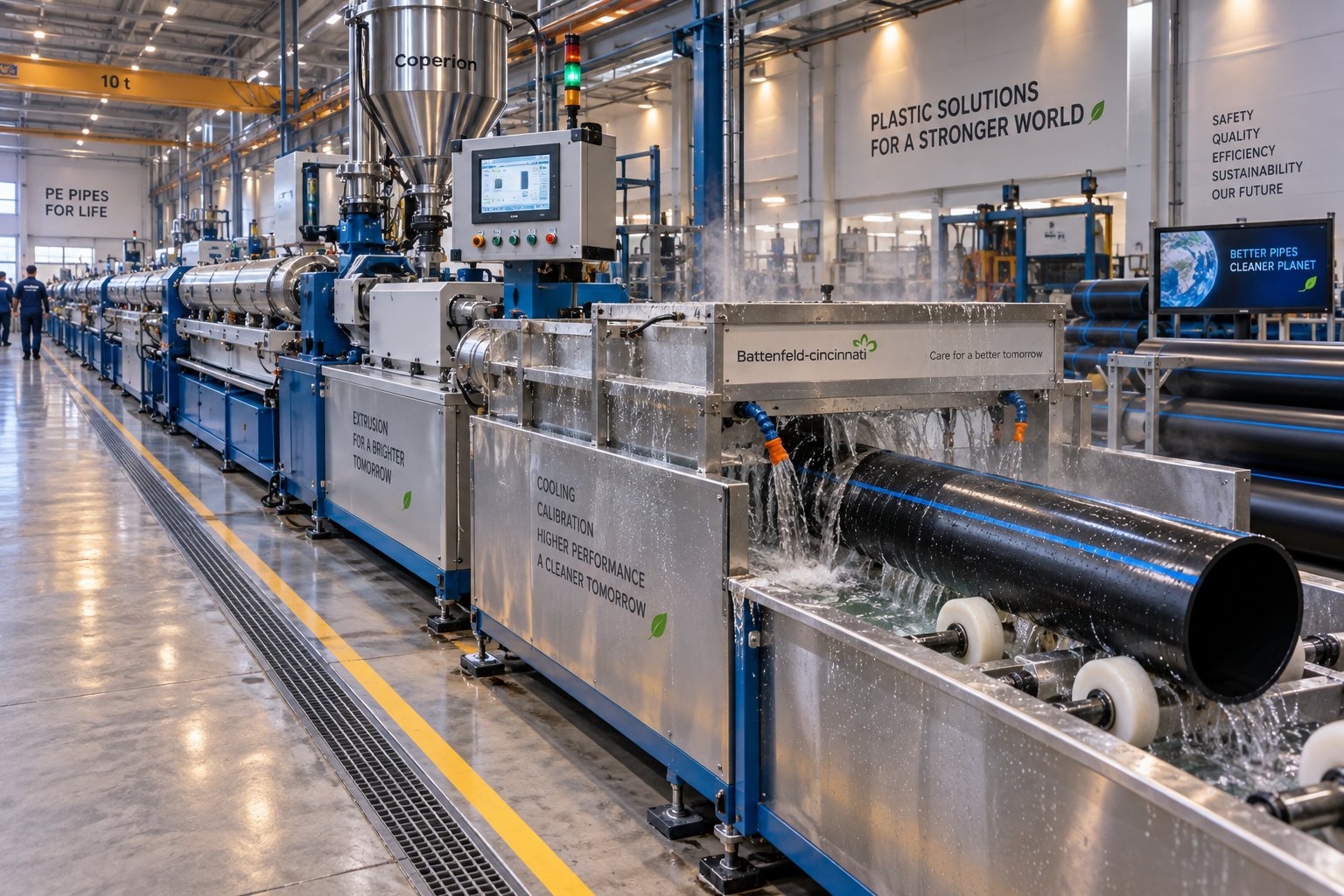
Imagine a machine that takes tiny polymer pellets or powder, melts them into a uniform stream, and shapes that stream into a continuous, perfectly round hollow pipe — all in one uninterrupted process. That machine is a plastic pipe extruder, and it sits at the very core of how the world produces the pipes running beneath our streets, through our walls, and across agricultural fields.
Defining the Plastic Pipe Extruder
So what is an extruder in the context of pipe manufacturing, and how does it differ from a general-purpose unit? The meaning of extruder, broadly speaking, refers to any machine that forces material through a shaped opening to create a continuous profile. A general-purpose extruder might produce flat film, sheet, or coating. A plastic pipe extruder, however, is purpose-built — its screw geometry, annular die head, and matched downstream equipment are all specifically engineered to form hollow cylindrical profiles from thermoplastic resins.
A plastic pipe extruder is a thermoplastic processing machine specifically configured in screw design, die head, and downstream calibration equipment to continuously convert polymer pellets or powder into hollow cylindrical profiles — pipes and tubes — with precise dimensional and mechanical properties.
That distinction matters. You can't simply bolt a pipe die onto any extruder and expect quality output. The screw's compression ratio, the barrel's heating zones, the vacuum sizing tank, and the haul-off speed all work as an integrated system. Change one variable, and the pipe's wall thickness, surface finish, or roundness can drift out of specification. Understanding what is extrusion in this specialized context helps buyers, engineers, and operators make smarter decisions at every stage — from equipment selection to daily production.
Why Pipe Extrusion Matters Across Industries
Plastic extrusion technology has quietly reshaped entire industries. Pipes made from PVC, HDPE, PP-R, PEX, and CPVC have largely replaced metal alternatives in plumbing, irrigation, gas distribution, sewage, and industrial fluid handling. The reasons are compelling: plastic pipes are corrosion-resistant, lighter, easier to install, and often more cost-effective over their lifecycle than copper, steel, or cast iron counterparts. PVC pipe alone carries a projected service life exceeding 100 years for underground installations, while PEX systems reduce carbon dioxide emissions by approximately 42% compared to copper in certain building applications.
Behind every meter of that pipe extrusion output stands the extruder — converting raw resin into a finished product at rates ranging from tens to hundreds of kilograms per hour. The machine's design determines not only throughput but also whether the pipe will pass hydrostatic pressure tests, meet potable water certifications, or survive decades buried underground.
This article walks you through the complete anatomy of a pipe extrusion line, the step-by-step process inside the barrel, screw and barrel design principles tailored to specific polymers, material-by-material processing guidance, defect troubleshooting, equipment selection criteria, automation trends, and the standards your finished pipe must meet. Whether you're specifying a new plastic pipe extruder, optimizing an existing line, or simply building a deeper technical understanding, every section ahead is designed to deliver practical, actionable knowledge.
The journey starts with what's physically inside the machine — and every component plays a role worth understanding.
Complete Anatomy of a Pipe Extrusion Line
A plastic pipe extruder doesn't work alone. It anchors an entire production chain — a pipe extrusion line — where every component upstream and downstream plays a direct role in whether the finished pipe holds its dimensions, surface quality, and mechanical integrity. Think of it like an orchestra: the extruder machine is the lead instrument, but the performance falls apart if even one section is out of tune.
Most descriptions of extrusion equipment stop at the extruder itself. That's a problem, because operators and buyers who don't understand the full line can't diagnose issues effectively or specify the right setup. Here's a walk through every major station, from the moment raw resin enters the hopper to the point a finished pipe lands on the stacker.
The Extruder Unit and Drive System
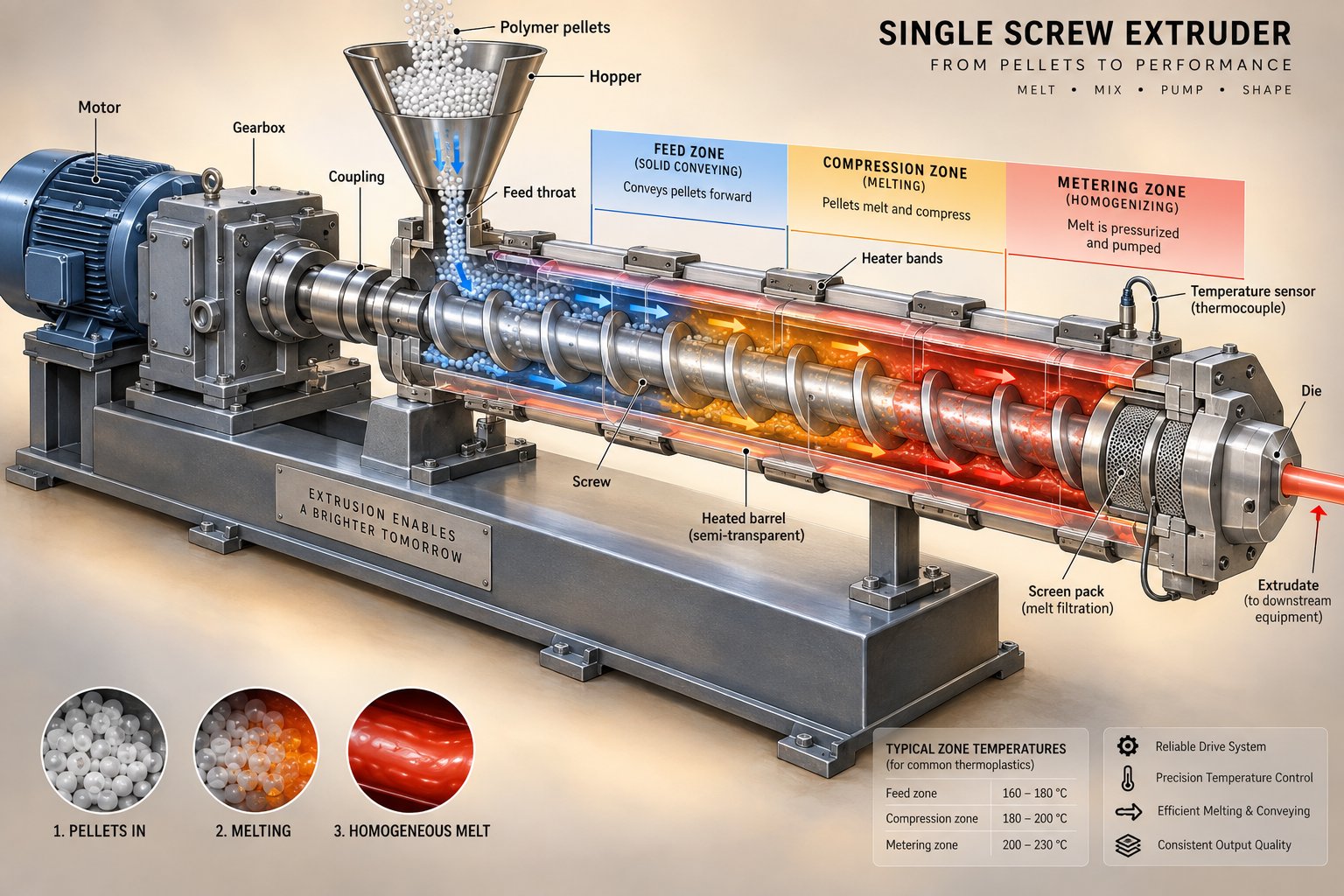
Everything begins at the feed hopper and gravimetric feeder. The hopper stores polymer pellets or dry-blend powder and delivers them into the barrel's feed throat. Gravimetric feeders weigh material in real time, ensuring a consistent mass flow rate. Why does this matter? Even small fluctuations in feed rate translate directly into wall thickness variation in the finished pipe. Volumetric feeders are cheaper, but gravimetric systems pay for themselves by reducing material waste and reject rates.
Beneath the hopper sits the drive motor — either a standard AC induction motor or an AC servo motor. Servo drives offer finer speed control, faster response to load changes, and higher energy efficiency, which is why they're increasingly common on modern pipe and profile extrusion equipment. The motor connects to the gearbox (gear reducer), which converts high motor speed into the high torque and lower RPM the screw needs. The extruder gearbox is one of the most mechanically stressed components on the line; its torque rating and reduction ratio must match the target throughput and the viscosity of the polymer being processed. An undersized gearbox limits output, while a mismatched ratio wastes energy and accelerates wear.
The screw is the heart of the extruder unit. Rotating inside the barrel, it conveys, compresses, melts, and homogenizes the polymer. Screw geometry — the flight depth, compression ratio, and length-to-diameter (L/D) ratio — determines melt quality, throughput, and energy efficiency. The barrel, meanwhile, provides the containment and external heating (and sometimes cooling) zones that work alongside the screw's mechanical shear to bring the polymer to its processing temperature. Worn screws or barrels cause melt leakback, inconsistent pressure, and degraded pipe quality.
At the barrel's discharge end, a screen changer filters the melt through fine mesh screens mounted on a breaker plate. This catches contaminants — unmelted particles, gels, or foreign material — before they reach the die. Continuous or slide-plate screen changers allow screen replacement without stopping the line, which is critical for high-output operations where downtime is expensive.
Die Head Configurations for Pipe
The die head transforms the filtered melt into a hollow annular profile — the basic pipe shape. Three main die head geometries dominate pipe production:
- Spider dies use support legs to hold the mandrel (inner core) in place. Melt flows around these legs and rejoins behind the mandrel. They're mechanically simpler, lighter, and faster to change over, making them popular for small-diameter pipe and PVC applications. The trade-off? Each support leg creates a weld line in the pipe wall, which can show up as localized wall thickness variation if leg balance is not carefully controlled.
- Spiral mandrel dies split the melt into channels that twist along the mandrel, recombining gradually. Because pressure builds progressively, these dies typically deliver the lowest circumferential wall variation — especially in the 16 to 160 mm diameter range. They're the default choice for PE and PP-R pressure pipe where tight tolerances are non-negotiable.
- Basket dies use a perforated sleeve to distribute melt evenly. They're less common but find use in specific applications where weld-line-free output and moderate tooling cost are both priorities.
Die selection isn't a brand preference — it's a process-control decision driven by the target resin, pipe diameter, tolerance window, and output rate.
Calibration, Cooling, and Cutting Equipment
The moment the hot, soft pipe exits the die, it enters the vacuum calibration (sizing) tank. Here, vacuum pressure pulls the pipe's outer surface against a calibration sleeve, establishing the target outside diameter and roundness while the pipe is still pliable. Unstable vacuum or worn calibration sleeves are among the most common sources of OD drift and ovality.
From the calibration tank, the pipe moves through spray or immersion cooling baths — sometimes a series of tanks stretching several meters. These remove residual heat progressively, locking in the pipe's dimensions and crystalline structure. Uniform cooling is essential: uneven water temperature or flow coverage can create residual stress, dimensional movement, or surface defects that only appear later in quality testing.
The haul-off unit pulls the pipe through the entire downstream section at a precisely controlled speed. Caterpillar-type haul-offs use paired rubber tracks or belts to grip the pipe evenly; belt-type designs serve larger diameters. Even minor speed instability in the haul-off can cause wall thickness fluctuation along the pipe's length, so modern units use servo-driven systems with closed-loop speed control.
At the end of the line, the cutting unit parts the continuous pipe into specified lengths. Planetary cutters orbit around the pipe and cut without stopping the line — ideal for high-speed production. A PVC saw or traveling saw is the alternative for larger diameter rigid pipe, where a clean, chipless cut face is required. Finally, a stacker collects straight pipe lengths for bundling, while a coiler winds flexible pipe (such as HDPE or PEX in smaller diameters) onto drums for shipping.
The table below maps each component to its function and its direct influence on finished pipe quality:
| Component | Function | Impact on Pipe Quality |
|---|---|---|
| Feed Hopper & Gravimetric Feeder | Stores and meters raw polymer into the barrel at a consistent mass flow rate | Feed inconsistency causes wall thickness variation and weight drift |
| Drive Motor (AC Servo or Induction) | Provides rotational power to the screw via the gearbox | Speed stability affects melt consistency and throughput uniformity |
| Gearbox / Gear Reducer | Converts motor speed to high-torque, low-RPM screw rotation | Torque limits and ratio mismatch restrict output and increase wear |
| Screw | Conveys, compresses, melts, and homogenizes the polymer | Geometry determines melt quality, pressure stability, and energy use |
| Barrel | Contains the polymer and provides external heating/cooling zones | Wear or poor zone control causes melt temperature variation and leakback |
| Screen Changer | Filters contaminants from the melt before the die | Contamination passing through causes surface defects and weak spots |
| Die Head (Spider / Spiral / Basket) | Shapes the melt into a hollow annular pipe profile | Die geometry and balance determine wall thickness uniformity and weld-line quality |
| Vacuum Calibration / Sizing Tank | Holds pipe OD and roundness under vacuum while the pipe is still soft | Unstable vacuum causes OD drift, ovality, and surface marks |
| Spray / Immersion Cooling Baths | Progressively remove heat to solidify the pipe | Uneven cooling creates residual stress, warping, or dimensional drift |
| Haul-Off Unit (Caterpillar / Belt) | Pulls the pipe through downstream equipment at controlled speed | Speed instability causes wall thickness variation along the pipe length |
| Cutting Unit (Planetary Cutter / Saw) | Cuts the continuous pipe to specified lengths | Poor cut quality affects joint integrity and end-use performance |
| Stacker or Coiler | Collects finished pipe for bundling or coiling | Improper handling can scratch surfaces or distort flexible pipe |
Every station in this extrusion line either creates the pipe's characteristics or preserves them. When dimensions start drifting — OD wandering, wall thickness varying, or ovality creeping in — the fix almost always traces back to a specific component in this chain. Understanding each one gives operators a diagnostic roadmap and gives buyers the vocabulary to specify exactly what they need.
Yet knowing what each component does is only half the picture. The real insight comes from understanding what physically happens to the polymer as it travels through the barrel, exits the die, and solidifies into a finished pipe — a transformation that unfolds in tightly controlled stages.
How the Pipe Extrusion Process Works Step by Step
You've seen the components lined up on the factory floor. But what actually happens to those small polymer pellets as they travel from the feed hopper to a finished, cut-to-length pipe? The plastic extrusion process is a continuous physical transformation — the polymer changes state, shape, and structure at every station. Understanding these changes is what separates operators who react to problems from those who prevent them.
Here's the full pipe extrusion process broken into its key stages. Whether the line produces rigid PVC drain pipe or flexible HDPE coils, the fundamental extrusion tube process follows the same sequence:
- Raw material feeding — Pellets or dry-blend powder enter the feed throat by gravity or gravimetric feeder.
- Solid conveying (feed zone) — The screw's deep flights push solid granules forward as a compacted plug.
- Compression and melting — Decreasing flight depth generates shear heat; barrel heaters supplement until the polymer transitions from solid to viscous melt.
- Melt homogenization (metering zone) — Shallow, consistent flights deliver a uniform-temperature, uniform-pressure melt to the screen changer.
- Melt filtration — The screen changer removes contaminants, gels, and unmelted particles.
- Die head shaping — The melt is distributed into a hollow annular profile around the die mandrel.
- Vacuum sizing — Vacuum pulls the soft pipe against a calibration sleeve to lock the outside diameter.
- Progressive cooling — Spray or immersion baths solidify the pipe wall without introducing residual stress.
- Haul-off — A caterpillar or belt puller draws the pipe at controlled speed, setting wall thickness.
- Precision cutting — A planetary cutter or traveling saw parts the pipe to specified lengths.
Each stage hands off to the next with zero interruption — the extrusion of pipes is a truly continuous process, and the polymer never stops moving from the moment it enters the barrel.
From Pellet to Melt — Inside the Extruder Barrel
Picture a solid polymer pellet — roughly 3 to 5 mm across, room temperature, and completely rigid. Within seconds of entering the barrel, that pellet begins a dramatic transformation.
In the feed zone, the screw's deep flights act like a conveyor, grabbing loose pellets and pushing them forward. Friction between the pellets, the barrel wall, and the screw surface compacts the granules into a dense plug. At this point, the polymer is still entirely solid — no melting has begun. Grooved feed sections (common on polyolefin extruders) increase friction against the barrel wall, boosting solids conveying pressure significantly.
As the plug advances into the compression zone, flight depth decreases progressively. The polymer is squeezed into a shrinking channel, and two heat sources converge: mechanical shear from the screw's rotation and conducted heat from the barrel's electric heater bands. Shear typically contributes the majority of the energy — often 60 to 80 percent — with barrel heaters supplying the balance. The polymer begins melting at the barrel wall, forming a thin melt film that grows inward. Solid pellets, melt pools, and partially melted material coexist in a dynamic, rapidly changing mix.
By the time material reaches the metering zone, the polymer should be fully molten and homogeneous. The shallow, constant-depth flights here serve a critical purpose: they generate consistent pressure and deliver the melt at a stable flow rate to the screen changer and die. Temperature uniformity matters enormously at this stage. A melt that varies by even a few degrees across its cross-section will produce wall thickness inconsistencies downstream — problems that no amount of calibration adjustment can fully correct.
Passing through the screen changer, the melt is forced through fine mesh screens that trap contaminants, degraded particles, and any remaining unmelted gels. For HDPE pipe production, melt temperatures in this zone typically range from 190 to 230 degrees Celsius depending on the resin grade. The filtered melt then enters the die head — and the shaping phase begins.
Shaping, Sizing, and Cooling the Pipe Profile
Inside the die head, the melt stream splits and flows around a central mandrel. In a spiral mandrel die, helical channels gradually recombine the flow into a seamless annular tube. In a spider die, the melt rejoins behind support legs. Either way, the polymer exits the die as a hot, soft, hollow cylinder — recognizable as a pipe in shape but far from finished.
This is where the tubing extrusion process diverges sharply from flat film or sheet production. The soft tube immediately enters the vacuum sizing tank, where negative pressure — typically 0.2 to 0.5 bar below atmospheric — draws the pipe outward against a precision calibration sleeve. That sleeve defines the exact outside diameter. Without stable vacuum, the pipe loses roundness and OD accuracy before it ever has a chance to solidify.
Simultaneously, cooling water begins removing heat. The pipe passes through spray zones or full immersion baths — sometimes stretching several meters — where water temperature and flow rate are carefully controlled. Cooling must be progressive and uniform. Quenching the outer surface too aggressively while the inner wall remains hot creates differential shrinkage, which locks residual stress into the pipe wall. That stress can cause the pipe to fail hydrostatic pressure testing later, even when its dimensions look perfect. For tube extrusion across materials like PE-RT and PP-R, where crystallization behavior is temperature-sensitive, cooling rate control becomes even more critical.
Haul-Off and Cutting for Dimensional Precision
By the time the pipe exits the final cooling bath, it's fully solidified — but its wall thickness isn't set by the die alone. The haul-off unit exerts the controlling influence. This caterpillar or belt puller draws the pipe through the entire downstream section at a precise, servo-controlled speed. The relationship is straightforward: increase haul-off speed relative to extruder output, and the wall thins; decrease it, and the wall thickens.
Even small speed fluctuations — fractions of a percent — produce measurable wall thickness variation along the pipe's length. That's why modern extrusion lines pair the haul-off with closed-loop control systems and inline ultrasonic wall thickness gauges. The gauge reads the wall in real time, and the control system adjusts haul-off speed to compensate.
Finally, the cutting station parts the continuous pipe into specified lengths. Planetary cutters orbit the pipe at line speed, producing chipless cuts without interrupting production — ideal for extrusion tubing and small to mid-diameter pipe. For larger rigid pipe, traveling saws provide clean, square-faced cuts suitable for socket or butt-fusion jointing.
What emerges at the end is a finished pipe whose diameter, wall thickness, surface quality, and mechanical properties were shaped — literally — at every stage of this process. Yet the quality of that transformation depends heavily on two components the polymer touches first: the screw and the barrel. Their design principles, tailored specifically to pipe production, deserve a much closer look.
Screw and Barrel Design Principles for Pipe Extrusion
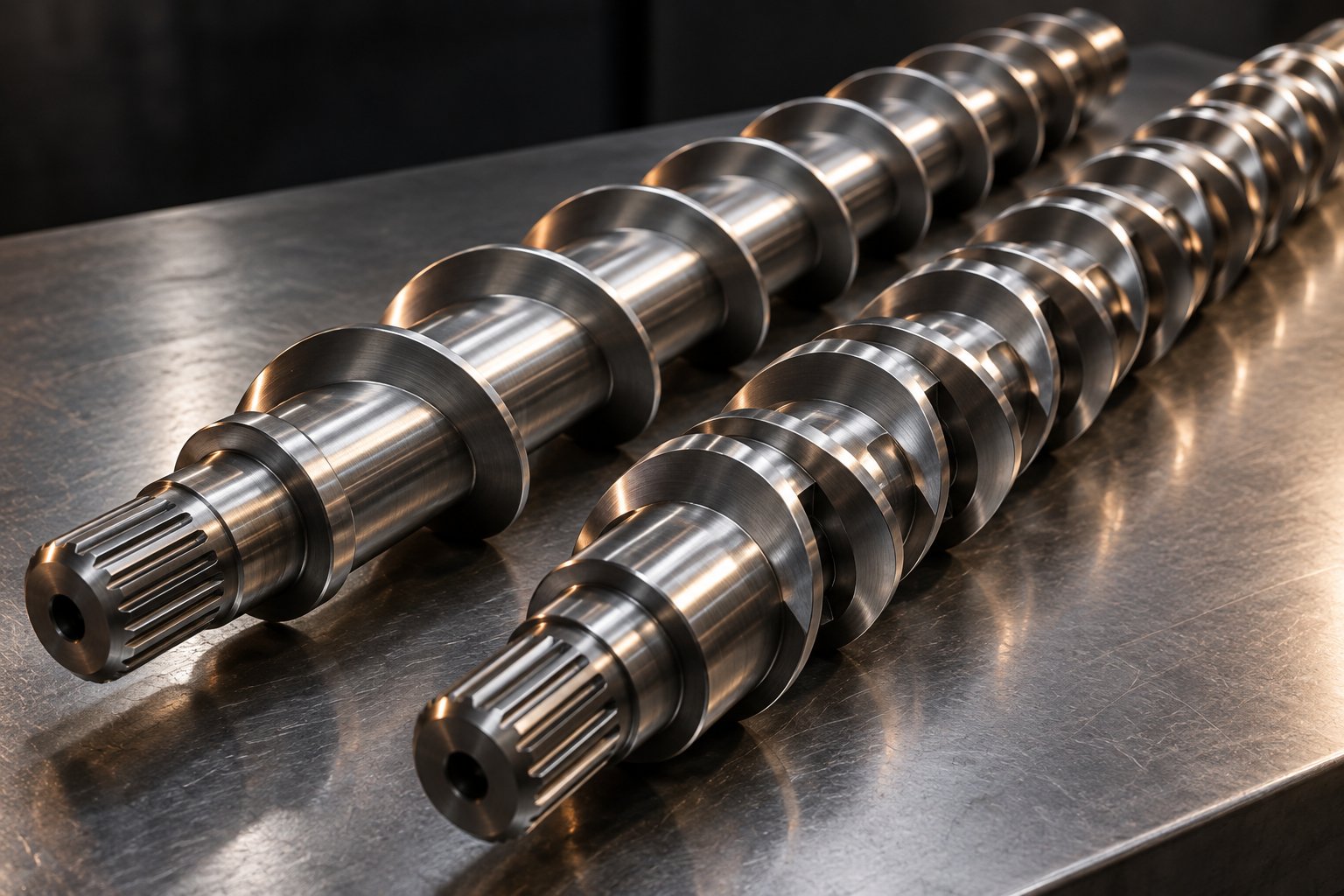
Every kilogram of polymer that becomes a finished pipe is shaped first by two components: the extruder screw and the barrel surrounding it. Their geometry, metallurgy, and interaction define melt quality before the polymer ever reaches the die. In polymer extrusion for pipe, generic screw designs rarely deliver optimal results — pipe-specific demands around pressure stability, melt homogeneity, and sustained throughput require deliberate engineering choices at the screw and barrel level.
Feed, Compression, and Metering Zones Explained
A single screw extruder designed for pipe production divides its working length into three functional zones, each performing a distinct job on the polymer:
- Feed zone — Deep flights convey solid pellets or powder forward as a compacted plug. Flight depth here is at its maximum, and the channel acts primarily as a solids conveyor. Consistent feeding in this zone prevents surging downstream.
- Compression (transition) zone — Flight depth decreases progressively, squeezing the polymer into a shrinking channel. This generates intense shear, which — combined with barrel heat — melts the resin. The ratio of feed-zone depth to metering-zone depth defines the compression ratio, a parameter tuned to the target polymer. HDPE pipe screws typically use ratios of 3:1 to 4:1, while heat-sensitive PVC demands gentler ratios closer to 2:1 to 2.5:1.
- Metering zone — Shallow, constant-depth flights homogenize the melt and build stable pressure for consistent die flow. Melt temperature uniformity at the exit of this zone directly determines wall thickness consistency in the finished pipe.
These three zones must work as a coordinated system. An oversized feed zone paired with an undersized metering section, for instance, creates excessive back-pressure and heat buildup that can degrade sensitive resins.
Several key design parameters govern how effectively the screw performs across all three zones:
- Compression ratio — Typically 2:1 to 4:1 for pipe; lower for PVC, higher for polyolefins.
- L/D ratio (length-to-diameter) — Generally 25:1 to 33:1 for pipe extruders. Longer screws provide more residence time for melting and mixing, improving homogeneity and throughput. A 30:1 L/D screw extruder is a common middle ground for HDPE and PP-R pipe.
- Flight depth — Deeper feed flights boost solids intake; shallower metering flights increase shear and pressure control.
- Helix angle — Typically 17.6 degrees (square pitch) for standard designs, though modified angles can fine-tune conveying efficiency for specific polymers.
- Channel width — Wider channels increase melting area, which directly influences melting capacity and output rate.
Barrier Screws vs. Conventional Designs
In a conventional single-flight screw, solid pellets and molten polymer share the same channel. As melting progresses, the solids bed can break apart and disperse randomly into the melt stream — a phenomenon that causes temperature inconsistencies and unmelted particles in the pipe wall. For demanding pipe applications, this is a serious quality risk.
Barrier screws solve this by introducing a secondary flight — the barrier flight — that physically separates the solids channel from the melt channel. Molten polymer passes over the barrier flight (which has a slightly reduced clearance) into the melt channel, while unmelted solids remain trapped until fully melted. The result is dramatically improved melt quality and higher melting capacity.
Not all barrier designs perform equally. Research comparing barrier screw families shows that the melting capacity of different barrier geometries varies significantly based on the solids-channel area in contact with the barrel wall. For a standardized 4.5-inch diameter screw at 10 barrier turns, modeled melting capacities for LDPE range from roughly 539 lb/hr for early Maillefer-type designs to approximately 798 lb/hr for Dray-type designs with wider parallel primary channels. Schippers/Barr parallel-channel variants fall between, near 697 lb/hr. The takeaway? Barrier screws are not interchangeable — the geometry of the primary melting channel determines real-world throughput differences of 20 to 40 percent between designs.
When should you choose one over the other? Barrier screws are the standard for high-output, high-quality pipe extrusion — especially for polyolefin pipe (HDPE, PP-R) where melt homogeneity and low melt temperature are critical. Conventional single-flight screws still serve adequately for lower-output lines, smaller pipe diameters, or situations where material changeovers are frequent and quick cleanability is a priority. Many modern extruders also pair barrier sections with downstream mixing elements — such as Maddock or pineapple mixers — to further refine melt uniformity before the die.
Barrel Construction and Wear Resistance
The barrel is far more than a passive housing. It provides the external heat transfer surfaces, contains enormous melt pressures, and endures constant abrasive contact with the polymer and any fillers it carries. The extruder feed barrel in particular sees the highest wear, since it handles solid granules under compression. Barrel condition directly influences pipe quality: a worn bore allows melt to leak back past the screw flights, reducing pressure stability and creating output surging that shows up as wall thickness variation.
Two barrel bore types serve different pipe applications:
- Smooth bore barrels — The conventional choice for most single screw extruder machine setups. The inner wall is a polished cylinder that relies on the friction differential between screw and barrel surfaces to convey solids forward.
- Grooved feed barrels — Feature machined axial grooves in the feed section, typically spanning 4 to 6 times the screw diameter in length, with 12 to 20 grooves around the circumference. These grooves "lock" pellets against the barrel wall, dramatically boosting solids conveying pressure and throughput — particularly valuable for polyolefin pipe extrusion (HDPE, PP) where the resin's low coefficient of friction would otherwise limit feeding efficiency. The grooved section requires dedicated water cooling to prevent premature melting that could block the grooves.
Barrel metallurgy determines service life and dimensional stability under heat and pressure. Three construction tiers are common across extruders used for pipe production:
- Nitrided steel barrels — The entry-level choice. Gas nitriding creates a hard surface layer (typically 55 to 70 HRC) that resists wear from unfilled polymers. Adequate for standard PVC or unfilled polyolefin pipe, but the hardened layer is thin and wears through faster when processing mineral-filled compounds.
- Bimetallic lined barrels — A centrifugally cast alloy liner (often iron-boron or nickel-based) is bonded inside a structural steel outer shell. These liners provide superior abrasion and corrosion resistance, extending barrel life significantly when running glass-fiber-reinforced, calcium-carbonate-filled, or recycled-content pipe formulations.
- Tungsten carbide or ceramic coatings — Reserved for the most aggressive applications, such as highly filled WPC profiles or abrasive recycled feedstocks.
A worn or poorly specified barrel doesn't just shorten its own life — it degrades output quality, increases energy consumption, and forces operators to compensate with suboptimal screw speeds or temperatures. When an extruding machine shows symptoms like declining output rate, increasing melt temperature at constant RPM, or visible wall thickness drift, barrel wear is a prime suspect. Replacing or upgrading the barrel restores performance in ways that no process adjustment alone can achieve.
For operators facing barrel replacement or upgrading an existing line, sourcing application-specific barrels matters. NANHAIYA's single screw barrels are engineered for specific extrusion applications — including pipe, film, sheet, pelletizing, and recycling lines — with bimetallic and nitrided options designed to match the polymer, filler content, and throughput demands of each production scenario. Having a barrel tailored to the actual operating conditions, rather than a generic replacement, can meaningfully extend service intervals and stabilize pipe quality.
Screw and barrel design choices are always material-dependent. The compression ratio, barrier geometry, feed section type, and barrel metallurgy that work beautifully for HDPE pipe may be entirely wrong for PVC or PP-R. Each major pipe polymer brings its own processing personality — and the extruder configuration must respect it.
Material-by-Material Pipe Extrusion Guide
A screw that runs HDPE pipe flawlessly could destroy a PVC compound in minutes. Every pipe polymer carries a distinct processing personality — different melt viscosity, thermal stability limits, crystallization behavior, and sensitivity to shear. Choosing the right plastic pipe extrusion machine configuration means starting with the material, not the equipment catalog. Here's what each major pipe resin demands.
PVC and CPVC Pipe Extrusion Considerations
PVC-U (unplasticized polyvinyl chloride) is the most widely extruded pipe material globally, yet it's also among the most unforgiving. The pvc extrusion process hinges on one critical fact: PVC degrades thermally at temperatures uncomfortably close to its processing window. Push the melt above roughly 205 degrees Celsius, and the polymer begins releasing hydrochloric acid — corroding equipment and producing discolored, brittle pipe.
This narrow thermal window is precisely why a counter-rotating twin screw extruder dominates PVC pipe production. Unlike single-screw machines, the intermeshing counter-rotating design offers positive conveying with lower shear intensity. The material spends less time under heat stress, and temperature control across the barrel zones is far more predictable. A typical pvc pipe extruder uses an L/D ratio of 20:1 to 25:1, shorter than polyolefin machines, because PVC's heat sensitivity demands minimal residence time.
CPVC pushes these challenges further. Its higher glass transition temperature requires processing at 200 to 230 degrees Celsius — even closer to its degradation threshold. A pvc extrusion machine running CPVC needs tighter zone-by-zone temperature control, chrome-plated or bimetallic barrel linings to resist corrosion from trace HCl, and screws designed with gentle compression ratios near 2:1. When shopping for a pvc pipe extrusion machine, confirming these corrosion-resistance features upfront saves costly barrel replacements later.
Polyolefin Pipe Extrusion — HDPE, PP-R, and PE-RT
Polyolefins are thermally robust compared to PVC, but they introduce different challenges — particularly around melt homogeneity and crystallization control.
HDPE pipe production relies almost exclusively on single-screw extruders with grooved feed sections. Why? HDPE pellets have a low coefficient of friction that makes smooth-bore feeding inefficient. Grooved feed barrels lock the pellets against the barrel wall, dramatically improving conveying pressure and throughput. Barrel temperatures typically range from 180 to 210 degrees Celsius, with die temperatures of 200 to 220 degrees Celsius. L/D ratios of 30:1 to 36:1 are standard, giving the screw enough length to fully homogenize HDPE's high-viscosity melt. Barrier screw designs excel here, ensuring no unmelted particles reach the die.
PP-R (polypropylene random copolymer) shares HDPE's preference for single-screw machines and grooved feed barrels. However, PP-R brings a unique complication: beta-phase crystallization. If the melt cools too rapidly or unevenly, beta-form crystals form preferentially, reducing the pipe's long-term hydrostatic strength. Processing temperatures typically run 200 to 240 degrees Celsius, and downstream cooling must be carefully staged — not quenched — to encourage the desired alpha-crystalline structure.
PE-RT (polyethylene of raised temperature resistance) processes similarly to HDPE but at slightly lower temperatures, typically 180 to 210 degrees Celsius. Its main advantage is that it doesn't require crosslinking, simplifying the extrusion line. PE-RT pipe finds heavy use in underfloor heating systems, often in multi-layer configurations with EVOH barrier layers.
Specialty Materials — PEX, ABS, and Multi-Layer Systems
PEX (crosslinked polyethylene) is unique because the extruder produces a standard HDPE pipe that is subsequently crosslinked — by peroxide (PEX-a), silane (PEX-b), or electron beam (PEX-c). For PEX-a, the crosslinking agent is mixed into the resin before extrusion, and the pipe exits the die already in a crosslinked state. This requires a ram extruder rather than a conventional screw machine, running at much lower speeds and higher pressures. PEX-b uses a standard single-screw extruder since crosslinking occurs in a post-extrusion moisture curing step. Each method demands fundamentally different line configurations despite producing pipes that look identical.
ABS (acrylonitrile butadiene styrene) pipe is processed on single-screw extruders at 200 to 240 degrees Celsius with L/D ratios of 25:1 to 30:1. ABS is hygroscopic, meaning moisture must be driven off through pre-drying before extrusion — typically at 80 degrees Celsius for two to four hours. Skipping this step produces bubbles and surface defects that compromise the pipe's chemical resistance.
Multi-layer co-extrusion represents the frontier of pipe technology. Systems like PE-RT/EVOH barrier pipes for underfloor heating combine a structural PE-RT pipe with adhesive tie layers and a thin EVOH oxygen barrier — all formed in a single pass through a multi-layer co-extrusion die. Modern five-layer co-extrusion lines use separate extruders for each material, feeding into a single die head with computer-controlled flow channels. The EVOH layer, despite being only fractions of a millimeter thick, reduces oxygen transmission to as low as 0.1 mg/l/day — protecting metallic heating system components from corrosion. Adhesive innovations using modified polyolefin tie layers have largely solved the delamination issues that plagued earlier generations of barrier pipe.
| Material | Extruder Type | Typical L/D Ratio | Processing Temp Range (°C) | Key Challenges |
|---|---|---|---|---|
| PVC-U | Counter-rotating twin screw | 20:1 – 25:1 | 160 – 200 | Thermal degradation; HCl release above ~205 °C; narrow processing window |
| CPVC | Counter-rotating twin screw | 20:1 – 25:1 | 200 – 230 | Even narrower stability margin; corrosion risk; requires corrosion-resistant barrels |
| HDPE | Single screw (grooved feed) | 30:1 – 36:1 | 180 – 220 | Low friction demands grooved feed; high melt viscosity requires barrier screws |
| PP-R | Single screw (grooved feed) | 30:1 – 33:1 | 200 – 240 | Beta-phase crystallization from improper cooling; precise thermal control essential |
| PE-RT | Single screw | 25:1 – 33:1 | 180 – 210 | Cooling rate sensitivity; multi-layer adhesion in EVOH barrier pipe |
| PEX-a | Ram extruder | N/A (ram type) | 200 – 250 | In-die crosslinking at high pressure; very low output speeds |
| PEX-b | Single screw | 25:1 – 30:1 | 180 – 220 | Post-extrusion silane curing requires moisture chamber; process time extended |
| ABS | Single screw | 25:1 – 30:1 | 200 – 240 | Hygroscopic; must pre-dry to prevent bubbles; sensitive to shear degradation |
Each row in this table represents a different set of demands on the extruder's screw geometry, barrel metallurgy, temperature control, and downstream equipment. A pvc extruder machine configured for rigid PVC-U drainage pipe shares almost no processing parameters with a single-screw HDPE line producing municipal water main. Material dictates machine — and getting that match wrong means fighting quality problems that no amount of downstream adjustment will fix.
Of course, even a perfectly matched extruder and material combination still produces defects when process variables drift. Recognizing those defects and tracing them back to their root causes is a skill every pipe extrusion operator needs — and it's exactly where most available guidance falls short.
Troubleshooting Common Defects in Extruded Pipes
A perfectly specified extruder running the ideal polymer can still produce reject pipe. Why? Because extrusion pipe quality depends on dozens of interacting variables — melt temperature, screw speed, vacuum pressure, cooling uniformity, haul-off tension — and when any of them drifts, defects appear in the finished product. The frustrating part? Many defects in extruded plastic pipe look similar on the surface but originate from completely different root causes inside the line.
Operators who can read a defect like a diagnostic clue — tracing a rough surface or an oval cross-section back to a specific machine setting or worn component — save hours of downtime and thousands of dollars in scrap. Here's a practical breakdown of the most common quality problems encountered in extruded pipe manufacturing, organized by where they show up.
Surface Defects and Their Extruder-Related Causes
Surface quality is the first thing you notice on an extruded pipe, and it's often the first indicator that something upstream has gone wrong.
Surface roughness typically signals that the polymer melt wasn't fully homogenized or reached the die at an inadequate temperature. When melt temperature runs too low, the resin doesn't flow smoothly through the die land, producing a matte or gritty finish. Contamination — degraded material buildup on the die lips or mandrel surfaces — creates streaks and longitudinal lines that transfer directly onto every meter of pipe produced. The fix starts with optimizing the barrel temperature profile and verifying that die surfaces are clean and polished.
Shark skin is a distinct surface defect where fine, regularly spaced ridges appear perpendicular to the extrusion direction. It's a melt fracture phenomenon driven by excessive shear stress at the die exit. When the polymer is forced through the die land too quickly or the land length is too short, the melt's elastic recovery creates these oscillating surface distortions. Reducing line speed, increasing melt temperature slightly, or using a die with a longer land length usually resolves the issue. According to industry reporting, roughly one-third of HDPE extrusion lines encounter melt fracture-related surface defects at some point during operation.
Burn marks and discoloration point to thermal degradation. When extruded plastic sits too long in a stagnant zone — dead spots in the die head, oversized transition areas, or behind damaged screen packs — the polymer overheats and breaks down. For PVC, this shows up as yellow or brown streaks; for polyolefins, dark specks or black spots. The root cause is almost always excessive residence time or localized overheating, and the corrective action involves cleaning or redesigning flow channels to eliminate dead zones, verifying heater band function, and checking that temperature controllers read accurately.
Dimensional Defects — Wall Thickness, Ovality, and Diameter Drift
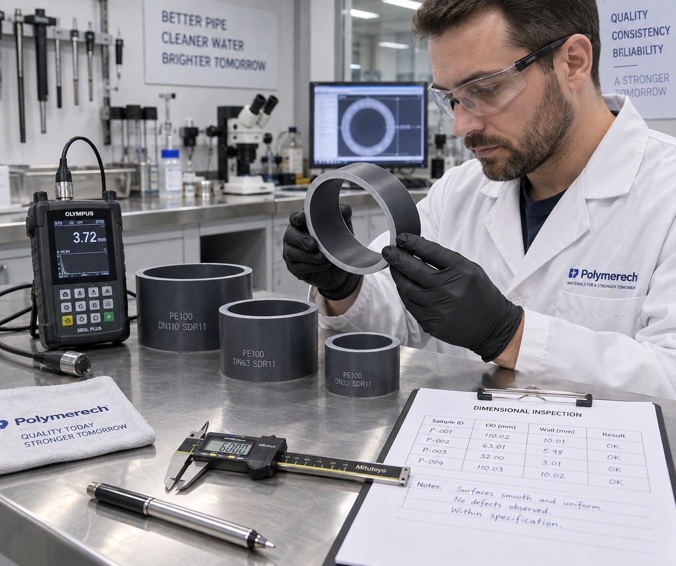
Dimensional problems are arguably more dangerous than surface flaws because they directly compromise the pipe's pressure rating and joint compatibility — and they can be invisible without measurement.
Wall thickness variation is the single most common dimensional defect. It can manifest circumferentially (one side thicker than the other) or longitudinally (thickness fluctuating along the pipe's length). Circumferential variation usually traces to die and mandrel misalignment or uneven die head temperature, which causes the melt to flow faster on the hotter side. Longitudinal variation points to feed surging (inconsistent material delivery from the hopper), worn screw flights allowing melt leakback, or haul-off speed instability. Switching from volumetric to gravimetric feeding alone can reduce feed variability by up to 70 percent.
Ovality — the pipe being elliptical rather than round — originates downstream of the die. Insufficient vacuum pressure in the calibration tank fails to hold the soft pipe firmly against the sizing sleeve. Non-uniform cooling spray patterns cause one side to shrink faster than the other. Even misalignment between the die head centerline and the downstream equipment can pull the pipe off-round. Proper correction requires checking vacuum pump capacity, cleaning spray nozzles for uniform coverage, and performing a full centerline alignment of the entire downstream train.
Diameter drift — gradual OD creep over a production run — often signals progressive die swell changes as melt temperature shifts, or worn calibration sleeves that no longer hold tolerance. Inline diameter gauges with closed-loop feedback to the haul-off or extruder speed catch this drift before it generates scrap.
Internal Defects — Voids, Bubbles, and Weld Lines
Internal defects are the most insidious because they're hidden from visual inspection. A pipe can look flawless on the outside while harboring voids that cause catastrophic failure under pressure.
Voids and bubbles almost always originate from moisture in the feedstock. Water trapped in polymer pellets vaporizes inside the barrel, creating steam pockets that travel through the die and freeze into the pipe wall as bubbles. For hygroscopic materials like ABS, pre-drying is non-negotiable. For polyolefins and PVC dry-blends, inadequate venting or a malfunctioning vacuum degassing system allows volatiles to remain trapped. The corrective path is straightforward: verify feedstock moisture levels, confirm that the extruder's vent port and vacuum system function correctly, and ensure material storage prevents moisture reabsorption.
Weld lines appear as faint longitudinal marks — or in severe cases, as weak planes — where the polymer melt splits around the die mandrel supports and then rejoins. Spider dies inherently produce weld lines; the question is whether they're strong enough to be cosmetically and structurally acceptable. Weak weld lines indicate insufficient melt pressure or temperature at the rejoin point, preventing full molecular entanglement across the interface. Increasing die temperature, optimizing the spider leg geometry, or switching to a spiral mandrel die that eliminates weld lines altogether are the primary solutions.
The table below consolidates these defects into a quick-reference diagnostic guide — the kind of resource operators can keep at the line for rapid troubleshooting when extruding plastic pipe:
| Defect | Symptoms | Root Causes | Corrective Actions |
|---|---|---|---|
| Wall Thickness Variation | Uneven circumferential or longitudinal wall; fails min-wall specification | Die/mandrel misalignment; uneven die temperature; feed surging; worn screw flights; haul-off speed instability | Re-center die and mandrel; balance die zone temperatures; switch to gravimetric feeding; inspect screw for wear; calibrate haul-off servo |
| Surface Roughness | Matte, gritty, or dull pipe surface instead of smooth gloss | Low melt temperature; incomplete plasticization; contamination on die surfaces | Raise barrel/die temperatures incrementally; clean and polish die lips and mandrel; check for degraded material buildup |
| Shark Skin | Fine, regular transverse ridges on the outer surface | Excessive shear stress at die exit; die land too short; line speed too high relative to melt elasticity | Reduce screw speed or line speed; increase melt temperature slightly; use die with longer land length |
| Ovality | Pipe cross-section is elliptical; fails roundness tolerance | Insufficient vacuum pressure; uneven spray cooling; downstream equipment misalignment; pipe sagging between supports | Verify vacuum pump capacity; clean and balance spray nozzles; laser-align downstream equipment; add support rollers |
| Burn Marks / Discoloration | Yellow, brown, or black streaks or specks on pipe surface | Excessive residence time; dead spots in die or adapter; overheating in barrel zones; degraded material trapped in flow path | Purge and clean die head; eliminate flow dead zones; verify heater band and thermocouple accuracy; reduce barrel temperatures if excessive |
| Voids / Bubbles | Internal cavities visible in cross-section or detected by ultrasonic testing | Moisture in feedstock; inadequate degassing/venting; entrapped air from hopper feed | Pre-dry hygroscopic resins; verify vacuum vent operation; check material storage conditions; ensure feed throat is not starve-fed in a way that traps air |
| Weld Lines | Visible longitudinal lines on inner or outer surface; weak longitudinal planes | Insufficient melt temperature or pressure at flow-rejoin point in spider die; poor spider leg geometry | Increase die temperature; optimize spider leg streamlining; consider switching to spiral mandrel die for critical pressure pipe applications |
| Diameter Drift | Gradual OD change over a production run; pipe moves out of spec over time | Progressive melt temperature shift; worn calibration sleeve; haul-off speed creep | Implement inline OD gauging with closed-loop feedback; replace worn calibration tooling; verify servo drive stability |
The fastest path to solving any extruded pipe defect is working backward from the symptom to the specific machine zone, component, or setting responsible — not guessing and adjusting randomly.
Every defect in extruded plastic tubing maps back to a specific point in the process chain. Surface problems usually originate at or near the die. Dimensional issues split between the extruder (feed consistency, screw wear) and the downstream section (vacuum, cooling, haul-off). Internal flaws point to material preparation or barrel venting. Training operators to think in terms of these cause-and-effect relationships — rather than simply tweaking whatever dial is closest — transforms troubleshooting from trial-and-error into systematic diagnosis.
Minimizing defects, however, is only part of the equation. Choosing the right extruder size, motor power, and line configuration for a specific pipe application prevents many of these problems from ever appearing in the first place — and that selection process involves its own set of critical decisions.
How to Select and Size the Right Pipe Extruder
Knowing what defects look like — and where they come from — is valuable. But a surprising number of quality problems trace back to something that happened long before the first pellet entered the barrel: the original equipment selection. An undersized pipe extruder struggles to maintain stable melt pressure. An oversized one runs at partial load, wasting energy and producing inconsistent flow. The right machine, matched precisely to your product and production goals, prevents entire categories of problems from ever surfacing.
So how do you navigate the decision? The temptation is to start browsing catalogs for the most impressive throughput numbers. Resist that instinct. As experienced machinery suppliers emphasize, the correct approach works in reverse — start with the pipe you need to produce and let the product specification drive every equipment choice downstream.
Matching Extruder Size to Pipe Diameter and Output
The first decision — single screw or twin screw — is dictated almost entirely by your target material. PVC-U and CPVC demand counter-rotating twin-screw pipe extrusion machinery for their shear sensitivity. HDPE, PP-R, PE-RT, and most other polyolefins run on single-screw machines with grooved feed sections. Get this wrong, and no amount of process optimization will compensate.
With the screw type settled, the next variable is screw diameter — and this is where the pipe extruder gets sized to the application. Screw diameter directly governs the range of pipe diameters and wall thicknesses a line can produce efficiently. Here's the general relationship:
| Screw Diameter (mm) | Typical Pipe OD Range (mm) | Approximate Throughput (kg/hr) | Typical Application |
|---|---|---|---|
| 45 – 50 | 16 – 63 | 30 – 80 | Small-diameter plumbing, drip irrigation, PP-R fittings pipe |
| 60 – 65 | 20 – 110 | 80 – 200 | Residential plumbing, underfloor heating, small industrial pipe |
| 75 – 90 | 50 – 315 | 200 – 500 | Municipal water supply, gas distribution, medium industrial |
| 100 – 120 | 110 – 630+ | 400 – 1000+ | Large-diameter water main, sewer, industrial pressure pipe |
These ranges overlap intentionally. A 75 mm screw can produce 50 mm pipe comfortably, but it can also stretch to 250 mm OD at lower wall thicknesses — just at reduced line speed and with different die tooling. The key trade-off? Versatility versus throughput. A plastic extruder machine with a larger screw handles a broader diameter range but costs more, consumes more energy, and takes up more floor space. A smaller, dedicated machine runs at peak efficiency within a narrower window.
Imagine you're producing 110 mm HDPE water pipe at SDR 11 (standard dimension ratio, meaning wall thickness equals 10 mm). Your target output is 250 kg/hr to meet order volumes. A 65 mm extruder could technically produce the pipe, but it would run near its maximum capacity — leaving no headroom for thicker walls, higher line speeds, or future product additions. A 75 mm or 90 mm plastic extruder machine gives breathing room and better melt quality at lower screw RPM, which translates to less shear heat and longer equipment life.
Motor Power, Torque, and Drive System Selection
Throughput targets don't just determine screw diameter — they also define the motor and gearbox requirements. The relationship is straightforward in principle but easy to get wrong in practice.
Motor power (measured in kW) must supply enough energy to melt, convey, and pressurize the polymer at the target throughput. As a rough guideline, specific energy consumption for polyolefin pipe extrusion typically falls between 0.20 and 0.35 kWh/kg, depending on the resin, screw design, and line efficiency. For a 300 kg/hr HDPE pipe extrusion machine, you'd need a motor in the 75 to 110 kW range — with the exact figure depending on the screw's efficiency and the gearbox losses.
Torque is equally important, especially at lower screw speeds where high-viscosity melts demand enormous rotational force. The gearbox reduction ratio converts high motor RPM (typically 1,000 to 1,800) into the 50 to 150 RPM range the screw operates at, multiplying torque in the process. An undersized gearbox becomes the bottleneck: it either limits maximum throughput or fails prematurely under sustained load. When evaluating an extruder line, always confirm that the gearbox torque rating matches the worst-case scenario — startup with cold polymer in the barrel — not just steady-state operation.
Modern extrusion lines increasingly use AC servo or permanent magnet motors paired with direct-drive gearboxes. These systems deliver faster response to load changes, tighter speed regulation (critical for wall thickness control), and measurably lower energy consumption compared to conventional induction motor setups. The upfront cost premium typically pays back within two to three years through reduced electricity bills on continuous-run extrusion lines.
Building a Complete Line Specification
Selecting the pipe extrusion machine itself is only one piece. You're specifying an entire plastic pipe production line — and every downstream component must be matched to the extruder's output capacity and the pipe's dimensional requirements. Before requesting quotes from any supplier, define these parameters clearly:
- Target material(s) — PVC-U, HDPE, PP-R, PE-RT, or multi-layer? This determines screw type, barrel metallurgy, and whether co-extrusion capability is needed.
- Pipe diameter range — Minimum and maximum OD you intend to produce, including future product plans.
- Wall thickness and pressure class — SDR values or specific wall dimensions; these set the die tooling and calibration sleeve inventory.
- Required throughput — Realistic kg/hr target at your primary pipe size, not the peak number from a brochure.
- Line speed — Meters per minute at each pipe size; directly linked to cooling tank length requirements.
- Quality and certification requirements — ISO, ASTM, NSF, or regional standards the pipe must meet; these influence temperature control precision and inline gauging needs.
- Utility availability — Electrical supply (voltage, frequency, available amperage), cooling water capacity, and compressed air.
- Floor space and plant layout — Total line length (often 20 to 40 meters for medium pipe) and building height constraints.
- Budget and total cost of ownership — Including energy consumption, spare parts availability, and expected maintenance intervals — not just purchase price.
One detail that's easy to overlook in this specification process: the screw and barrel themselves. These are wear components that will eventually need replacement, and their design must match both the polymer and the output target precisely. A barrel engineered for unfilled HDPE won't survive long running calcium-carbonate-filled PVC. Sourcing application-specific replacements from the start avoids the trap of generic parts that underperform. NANHAIYA's custom single screw barrels, for example, are designed to match specific pipe materials and throughput demands — with bimetallic and nitrided options covering pipe, film, sheet, pelletizing, and recycling applications. Building this sourcing relationship into your line specification means barrel replacements restore original performance rather than introducing new variables.
The trade-off between single-line versatility and dedicated high-output configurations deserves a final word. A single, flexible extrusion line that handles 20 mm PP-R up to 315 mm HDPE sounds appealing — but in practice, the changeover time, tooling inventory, and process re-optimization required for each product switch eat into productive hours. High-volume producers often find that two dedicated extrusion lines — each optimized for a specific diameter range — deliver better total output and lower cost per meter than one do-everything line running at partial efficiency. The decision depends on your product mix, order patterns, and growth trajectory.
Getting the selection right puts you in a strong starting position. Keeping the line performing at that level year after year, however, depends on what happens after installation — the automation systems, process controls, and energy management strategies that separate modern extrusion manufacturing from the manually tuned lines of a decade ago.
Automation, Energy Efficiency, and Emerging Trends in Pipe Extrusion
A well-selected, properly sized plastic pipe extruder is only as good as the systems controlling it. Two operators running identical extrusion production lines with the same resin and die tooling can produce dramatically different results — one hitting tight tolerances with minimal scrap, the other chasing wall thickness drift all shift long. The difference? Increasingly, it comes down to automation, sensor integration, and how intelligently the line manages energy. Modern plastics extrusion has moved far beyond manual dials and operator intuition.
Process Sensors and Closed-Loop Control
Imagine adjusting barrel temperatures based on a thermocouple reading that updates every few seconds — while the melt pressure fluctuates invisibly between readings. That's how many older lines still operate, and it's a recipe for inconsistency. Modern plastic extrusion machines close this gap by embedding sensors at every critical point and linking them into automated feedback loops.
The most impactful sensors on a pipe extrusion line include:
- Melt pressure transducers — Installed at the barrel discharge and die entry, these detect pressure fluctuations caused by feed surging, screen blockage, or screw wear. A closed-loop system can automatically adjust screw speed in response, maintaining stable die pressure and consistent output.
- Melt temperature sensors — Infrared or immersion-type probes measure the actual polymer temperature (not just barrel wall temperature). When melt temperature drifts, the control system trims barrel zone heaters or adjusts screw RPM to compensate — preventing the quality problems discussed in the troubleshooting section.
- Ultrasonic wall thickness gauges — Mounted downstream of the calibration tank, these measure pipe wall thickness at multiple points around the circumference, updating several times per second. The readings feed back to the haul-off speed controller and, on advanced lines, to the die centering system. This single technology eliminates the most common dimensional defect — wall thickness variation — by catching it within seconds of its onset rather than after meters of off-spec pipe have been produced.
- Gravimetric feeders with real-time weight feedback — Continuously weigh the resin entering the barrel, adjusting feed rate to maintain a target mass flow. This replaces volumetric feeding's inherent variability with precision dosing that stabilizes both output rate and pipe weight per meter.
The critical concept here is closed-loop control. Each sensor doesn't just display a number for an operator to interpret — it feeds directly into a control algorithm that makes corrections automatically, faster and more consistently than any human could. The result is tighter process windows, less scrap, and fewer manual interventions per shift.
Industry 4.0 and IoT-Enabled Pipe Extrusion
Sensors and feedback loops have existed for decades. What's changed is how the data they generate is connected, stored, and analyzed. The convergence of operational technology and information technology — a hallmark of Industry 4.0 in manufacturing — is reshaping how extrusion lines are managed.
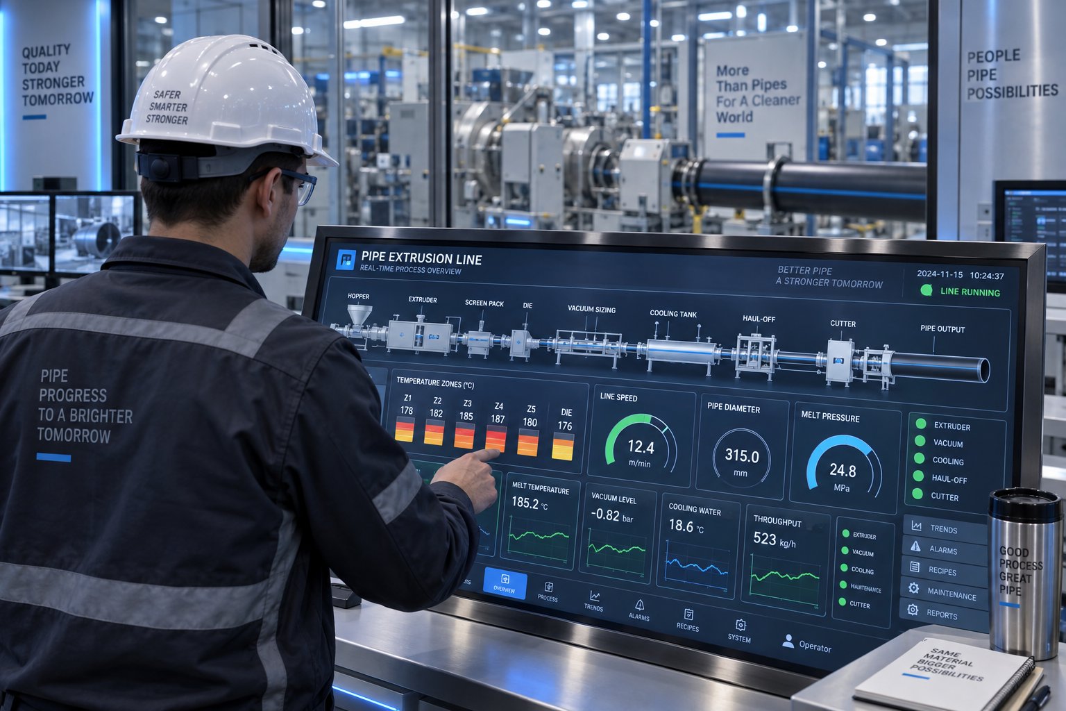
On a modern high-performance extrusion machine, a centralized SCADA (Supervisory Control and Data Acquisition) or HMI (Human-Machine Interface) system ties together every component — from the gravimetric feeder through the extruder, die head, calibration tank, cooling baths, haul-off, and cutter. Operators monitor and adjust the entire line from a single touchscreen rather than walking between individual control panels. Recipe management is fully automated: switching from 110 mm SDR 11 HDPE pipe to 63 mm SDR 17 means loading a stored recipe that sets every temperature zone, screw speed, vacuum level, haul-off rate, and cutter length simultaneously.
Beyond line-level control, IoT connectivity pushes extrusion data to cloud platforms for longer-term analysis. You'll notice the impact in several practical ways:
- Predictive maintenance — Vibration sensors on the gearbox and motor, combined with historical trend data, flag bearing wear or alignment drift weeks before a failure would halt production. AI models trained on historical sensor patterns identify anomalies that human operators would miss.
- Production analytics — Dashboards tracking OEE (Overall Equipment Effectiveness), scrap rates, specific energy consumption, and throughput per shift expose inefficiencies that accumulate silently over months.
- Remote diagnostics — Equipment suppliers can access line data remotely, diagnosing issues or optimizing recipes without an on-site visit — reducing downtime from days to hours.
- Digital twins — Virtual replicas of the extrusion production line allow engineers to simulate recipe changes, test new materials, or predict the effect of a screw speed increase before applying it to the physical machine.
This isn't theoretical. Leading manufacturers of machines for plastic pipe production are embedding these capabilities as standard features, not premium add-ons. The competitive pressure is real: extrusion manufacturing operations that leverage data-driven process control consistently achieve lower scrap rates, faster changeovers, and higher uptime than those relying on manual supervision alone.
Energy Efficiency and Operational Cost Reduction
Energy is one of the largest variable costs in pipe extrusion — and one of the least scrutinized. Most buyers focus on purchase price and throughput, overlooking the fact that electricity costs over a line's 15- to 20-year lifespan often exceed the original equipment investment. A plastic extrusion machine that consumes 15 percent less energy per kilogram of pipe produced delivers savings that compound every hour the line runs.
Several design choices determine how efficiently an extrusion machine converts electricity into finished pipe:
- Direct-drive vs. gearbox-driven extruders — Conventional setups pair a high-speed AC induction motor with a gearbox that reduces speed and multiplies torque. Every gear stage introduces friction losses — typically 3 to 5 percent per reduction stage. Direct-drive systems use low-speed, high-torque permanent magnet motors coupled directly to the screw, eliminating gearbox losses entirely. The energy savings typically reach 10 to 15 percent, and the reduced mechanical complexity means lower maintenance costs and quieter operation.
- IE4 and IE5 premium-efficiency motors — Motor efficiency classes defined by IEC 60034-30-1 range from IE1 (standard) through IE5 (ultra-premium). Upgrading from an IE2 to an IE4 motor on a 90 kW extruder drive can save 3 to 5 percent of motor input energy — a meaningful reduction when the motor runs 6,000 or more hours per year.
- Barrel insulation — Uninsulated barrels radiate significant heat to the factory environment, wasting energy and increasing cooling load. Insulation blankets applied to barrel heater zones reduce radiated heat loss by up to 40 percent, lower zone recovery time, and improve temperature stability — benefiting both energy bills and pipe quality simultaneously.
- Variable-frequency drives (VFDs) — Applied to cooling water pumps, vacuum pumps, and auxiliary motors, VFDs match motor speed to actual demand rather than running at full speed continuously. A vacuum pump that runs at 60 percent speed when full vacuum isn't needed consumes roughly 20 percent of the energy it would at full speed — a consequence of the cubic relationship between speed and power in pump applications.
The metric that ties all of this together is specific energy consumption (SEC), measured in kilowatt-hours per kilogram of pipe produced (kWh/kg). SEC captures the net efficiency of the entire line — motor, screw, barrel heating, cooling, haul-off, and auxiliaries combined. A well-optimized HDPE pipe line typically achieves SEC values of 0.20 to 0.30 kWh/kg, while poorly configured or aging lines can exceed 0.40 kWh/kg. Tracking SEC as a key performance indicator gives operations managers a single number that reflects both equipment condition and process optimization — and makes the financial case for upgrades concrete and measurable.
Specific energy consumption (kWh/kg) is the single most important metric for comparing the true operational efficiency of any pipe extrusion line — it captures motor efficiency, screw design effectiveness, thermal management, and downstream power consumption in one measurable number.
Energy efficiency, automation, and real-time process control aren't luxuries reserved for the largest producers. They're rapidly becoming baseline expectations — the cost of staying competitive in extrusion manufacturing where margins tighten every year. Yet even the most automated, energy-efficient line produces pipe that must meet external requirements beyond internal quality targets. The standards and certifications governing plastic pipe — and how extruder settings directly determine whether the finished product passes or fails — carry their own set of critical details.
Industry Standards and Certifications for Pipe Extrusion
An automated, energy-efficient plastic pipe extrusion line can churn out thousands of meters per day — but none of that output matters if it doesn't meet the standards governing the end-use application. A water utility won't accept HDPE pipe that hasn't passed hydrostatic pressure testing per ISO 4427. A gas distribution company won't install PE pipe lacking the required slow crack growth resistance certification. Standards aren't bureaucratic hurdles — they're the gatekeepers that determine whether your pipe can legally and safely enter the market.
Global Standards for Plastic Pipe Production
Plastic pipe standards vary by region, material, and application, but they share a common purpose: defining the minimum performance requirements a pipe must meet for safe, reliable long-term service. Engineers and procurement teams specifying a plastic pipe extrusion line need to know which standards apply before the first meter of pipe is produced — because those standards dictate everything from resin selection to dimensional tolerances to testing frequency.
Here's a reference table covering the most widely applied standards across major pipe materials and applications:
| Standard | Material | Application | Key Requirements |
|---|---|---|---|
| ISO 4427 | PE (HDPE, PE100, PE80) | Potable water supply and pressure pipe | Minimum Required Strength (MRS) classification; hydrostatic pressure testing at 20°C and 80°C; dimensional tolerances for OD and wall thickness; oxidative induction time (OIT) for long-term stability |
| ISO 1452 | PVC-U | Water supply and pressure applications | Burst pressure performance; impact resistance at 0°C; reversion testing to verify residual stress; dimensional accuracy per SDR class |
| EN 12201 | PE | Water supply (European harmonized) | Similar to ISO 4427 with additional European compliance markings; slow crack growth resistance (FNCT or full notch creep test); rapid crack propagation (RCP) resistance for larger diameters |
| ASTM D2241 | PVC | Pressure-rated PVC pipe (North America) | Sustained pressure testing per ASTM D1598; burst pressure per ASTM D1599; acetone immersion testing for proper fusion; dimensional requirements by SDR |
| ASTM F714 | HDPE | Large-diameter PE pipe (12" and above) | Cell classification per ASTM D3350; hydrostatic design basis; environmental stress crack resistance (ESCR); carbon black content and dispersion for UV protection |
| NSF/ANSI 61 | All pipe materials | Potable water contact (North America) | Extraction testing to verify that pipe materials do not leach harmful substances into drinking water above established maximum contaminant levels |
| NSF/ANSI 14 | PVC, CPVC | Plastic piping system components | Dimensional verification; pressure testing; material compound qualification; third-party certification audits |
| ISO 15874 | PP-R | Hot and cold water plumbing | Long-term hydrostatic strength at elevated temperatures (70°C, 95°C); impact resistance; thermal cycling endurance |
Regional differences matter. A pvc pipe extrusion line serving the European market must produce pipe conforming to EN-series standards with CE marking, while the same product for North American distribution requires ASTM compliance and often NSF certification. Pipe extruders themselves aren't directly certified — the finished pipe is — but every machine parameter feeds directly into whether that pipe passes or fails its certification tests.
How Extruder Settings Impact Standards Compliance
Here's what many operators underestimate: standards compliance isn't just about using the right resin grade. Two identical resin batches processed on the same extrusion pipe machine can produce pipe that passes every test — or pipe that fails catastrophically — depending entirely on how the extruder and downstream equipment were set up.
Consider a few concrete examples:
- Melt temperature and hydrostatic strength — Processing HDPE at excessively high melt temperatures degrades the polymer's molecular weight, reducing its long-term hydrostatic strength. A pipe that measures dimensionally perfect can still fail the 1,000-hour sustained pressure test at 80°C required by ISO 4427 because the resin was thermally damaged inside the barrel. Keeping melt temperature within the resin manufacturer's recommended window isn't optional — it's a certification requirement in practice.
- Cooling rate and residual stress — Rapid, uneven cooling locks internal stresses into the pipe wall. These stresses are invisible to dimensional inspection but show up dramatically during reversion testing — where a pipe sample is heated in an oven and measured for longitudinal shrinkage. ISO 1452 for PVC-U pipe, for example, limits reversion to 5 percent or less. A pvc pipe extrusion line with undersized or poorly balanced cooling baths routinely produces pipe that exceeds this threshold, triggering test failures and product rejection.
- Screw speed and material degradation — Running the screw too fast increases shear heat, especially in the compression zone. For PVC, this pushes the compound toward thermal decomposition — reducing impact strength at 0°C, a critical test parameter in both ISO 1452 and ASTM D2241. The temptation to maximize throughput by increasing RPM has a direct standards cost.
- Wall thickness consistency — Every pipe standard specifies minimum wall thickness at any point around the circumference. A pipe with an average wall thickness meeting the target but a localized thin spot below the minimum fails inspection. As discussed in earlier sections, wall thickness uniformity depends on die centering, feed consistency, and haul-off stability — all extruder-controlled variables.
The takeaway is clear: standards compliance is baked into the process, not bolted on at the end. Every barrel temperature setting, every screw RPM decision, every vacuum pressure adjustment either moves the finished pipe toward certification or away from it.
Certification Processes and Quality Assurance
Passing a lab test once doesn't equal certification. Formal certification programs — administered by bodies like NSF International, DVGW (Germany), WRAS (UK), or Kiwa (Netherlands) — require ongoing compliance. The typical certification process involves several layers:
- Material qualification — The resin compound itself must be independently tested and listed for the intended application. Pipe producers cannot substitute an uncertified resin grade, even if it appears chemically similar.
- Product testing — Finished pipe samples undergo the full battery of mechanical, dimensional, and chemical tests required by the applicable standard. For plastic pipe extrusion targeting potable water, this includes extraction testing under NSF/ANSI 61 to ensure no harmful substances leach into the water supply.
- Factory audit — Certification bodies conduct on-site audits of the production facility, verifying that the extrusion pipe machine settings, quality control procedures, raw material handling, and traceability systems meet documented requirements.
- Ongoing surveillance — Certified producers face periodic unannounced audits and random product sampling. Losing certification due to a failed surveillance test halts sales into regulated markets — a costly disruption that underscores why consistent process control matters every shift, not just during scheduled testing.
Standards certification for plastic pipe is not a one-time achievement — it is a continuous obligation that demands consistent extruder settings, verified raw materials, and documented quality controls on every production run.
For engineers and procurement teams evaluating a new plastic pipe extrusion line — or upgrading an existing one — building standards compliance into the equipment specification from the start is far more efficient than retrofitting controls later. The automation and sensor systems covered earlier in this article aren't just productivity tools; they're compliance infrastructure. Inline wall thickness gauging, automated recipe management, and traceable process data logging all serve double duty: optimizing production efficiency while simultaneously generating the documented evidence that certification auditors require. In this sense, every technical decision explored throughout this article — from screw geometry to cooling tank length to energy management — converges on a single outcome: producing pipe that performs reliably, passes every required test, and earns the certifications that open market access.
Frequently Asked Questions About Plastic Pipe Extruders
1. What is the difference between a single screw and twin screw extruder for pipe production?
The choice depends primarily on the polymer being processed. Counter-rotating twin screw extruders are preferred for heat-sensitive materials like PVC-U and CPVC because they offer positive conveying with lower shear intensity, reducing the risk of thermal degradation. Single screw extruders — often equipped with grooved feed barrels — are the standard for polyolefins such as HDPE and PP-R, where higher melt viscosity and the need for deep melt homogenization favor longer L/D ratios (30:1 to 36:1) and barrier screw designs. Selecting the wrong screw type for a given resin leads to persistent quality issues that process adjustments alone cannot resolve.
2. What causes wall thickness variation in extruded plastic pipes?
Wall thickness variation is the most common dimensional defect and can be circumferential or longitudinal. Circumferential variation — one side thicker than the other — typically results from die and mandrel misalignment or uneven die head temperatures causing asymmetric melt flow. Longitudinal variation, where thickness fluctuates along the pipe length, usually traces to feed surging from inconsistent material delivery, worn screw flights allowing melt leakback, or haul-off speed instability. Upgrading from volumetric to gravimetric feeding, inspecting screws and barrels for wear, and calibrating servo-driven haul-off systems are the most effective corrective measures.
3. How do I choose the right screw diameter for my pipe extrusion line?
Screw diameter directly governs the achievable pipe diameter range and throughput capacity. Smaller screws (45-50 mm) suit pipe ODs from 16-63 mm at outputs of 30-80 kg/hr, ideal for drip irrigation or small plumbing pipe. Mid-range screws (75-90 mm) handle 50-315 mm OD pipes at 200-500 kg/hr for municipal water and gas distribution. Large screws (100-120 mm) produce pipes up to 630 mm and beyond at over 1,000 kg/hr. It is important to size the extruder with headroom above your primary throughput target to allow for future product additions, thicker wall schedules, and extended equipment life at moderate RPM. Suppliers like NANHAIYA offer custom single screw barrels matched to specific pipe materials and output demands.
4. What is specific energy consumption (SEC) and why does it matter in pipe extrusion?
Specific energy consumption (SEC), measured in kilowatt-hours per kilogram of pipe produced (kWh/kg), is the most comprehensive metric for evaluating a pipe extrusion line's operational efficiency. It captures the combined efficiency of the motor, screw design, barrel heating, cooling systems, haul-off, and all auxiliaries in a single number. A well-optimized HDPE pipe line typically achieves SEC values of 0.20 to 0.30 kWh/kg, while poorly configured or aging lines can exceed 0.40 kWh/kg. Since electricity costs over a line's 15- to 20-year lifespan often surpass the original equipment investment, tracking SEC helps operations managers identify upgrade opportunities and quantify real savings from improvements like direct-drive motors, barrel insulation, or variable-frequency drives on auxiliary pumps.
5. What industry standards must extruded plastic pipes meet for potable water applications?
Pipes intended for potable water contact must comply with both material performance standards and health-safety extraction standards. Globally, ISO 4427 governs PE pressure pipe (requiring hydrostatic testing at 20 degrees C and 80 degrees C, plus oxidative induction time verification), while ISO 1452 covers PVC-U water pipe. In North America, ASTM D2241 applies to PVC pressure pipe, ASTM F714 to large-diameter HDPE, and NSF/ANSI 61 mandates extraction testing to confirm that pipe materials do not leach harmful substances above established limits. European markets require EN 12201 compliance with CE marking. Certification is not a one-time event — it involves ongoing factory audits, random product sampling, and documented process controls to maintain listing status.
Written by
Nanhaiya Technical Team
Zhoushan Nanhaiya Plastic Machinery Co., Ltd.
The Nanhaiya technical team supports screw and barrel manufacturing projects through application review, technical communication, custom manufacturing coordination, and production and quality control.
Discuss Your Application
Related Articles
More insights on screw barrel technology and plastics processing.
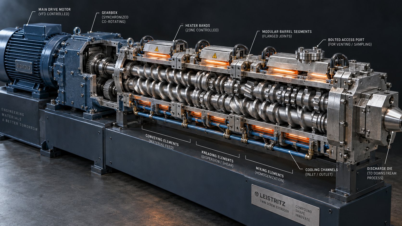
Co Rotating Twin Screw Extruder Parts: From Drive To Die Face
Oct 12, 2026
Complete guide to co rotating twin screw extruder parts — screw elements, kneading blocks, barrel segments, drive components, and material grades explained for sourcing and optimization.
Read Article
When Fixes Backfire: Extrusion Problems and Solutions Explained
Oct 12, 2026
Learn how to systematically diagnose and fix extrusion problems using a four-domain framework. Covers surface defects, surging, dimensional drift, material-specific fixes, and screw barrel design.
Read Article
What Nobody Tells You About Screw Barrel For Plastic Machine Design
Oct 10, 2026
Learn how screw barrel for plastic machine design affects melt quality, throughput, and wear life. Covers geometry, resin matching, troubleshooting, and sourcing.
Read ArticleLooking for something else?
Search by material, symptom or product and jump straight to the relevant page.
These are navigation suggestions based on keyword matching — not a quotation, not a delivery commitment, and not a substitute for engineering review. Final specification is confirmed by our engineers against your drawings and processed material.
Need help with screw barrel selection?
Share your machine model, processed material and application. Our team can help with pricing and technical support.